汽车模块编程器XPROG-M操作手册中文版
汽车配件管理软件操作手册

汽车配件管理软件操作手册汽车配件管理软件操作手册江苏省电信有限公司索引1 登陆平台 .。
..。
...。
.。
.。
.。
.。
..。
.。
..。
....。
..。
..。
..。
.。
.......。
.。
.。
..。
.。
.。
..。
.。
.。
.。
.。
..。
..。
.。
.。
.。
.。
.。
.。
..。
.。
.。
.。
5 2 ASUPERCRM包含的业务范围。
..。
.。
.。
.。
....。
...。
...。
.。
.。
.。
.。
.。
.。
.....。
.。
....。
.。
.。
.....。
7 3 主页面 ......。
.。
..。
..。
..。
.。
..。
..。
..。
.。
..。
.。
.。
..。
.。
.。
..。
..。
.。
.。
.。
.。
.。
.。
.。
.。
.。
..。
.。
.....。
.。
.。
.。
.。
...。
.。
.。
.。
9 3。
1 业务流程图。
.。
.。
..。
..。
.。
.。
.。
.。
.。
..。
...。
.。
.。
.。
...。
.。
.。
.。
.。
.。
.。
.。
...。
.。
.。
.。
..。
....。
.. 9 3.2 快捷新建功能。
..。
.。
.。
.。
..。
...。
..。
.。
.。
.。
.。
..。
..。
.。
.。
..。
.。
.。
.。
..。
.。
..。
.。
...。
.。
....。
9 3。
3 全局搜索功能。
..。
.。
.。
..。
.。
.。
.。
.。
..。
.。
.....。
.。
.。
....。
..。
.。
..。
.。
.。
..。
.。
....。
...。
.。
..。
.。
...。
.。
.。
. 9 3。
4 配置主页 .。
.。
.。
.。
.。
...。
..。
...。
.。
.。
.。
..。
.。
.。
.。
....。
.。
...。
..。
.。
.。
..。
.。
..。
.。
..。
..。
.。
..。
.。
.。
..。
9 4 基本操作 .。
..。
.。
.。
..。
.。
.。
...。
.。
..。
.。
..。
.。
..。
.。
.。
..。
....。
...。
...。
.。
..。
.。
.。
....。
..。
....。
.。
.....。
..。
.。
....。
.。
.。
.。
. 11 4。
1 系统工具菜单 .。
.。
..。
FlashPro6 车辆编程器说明书
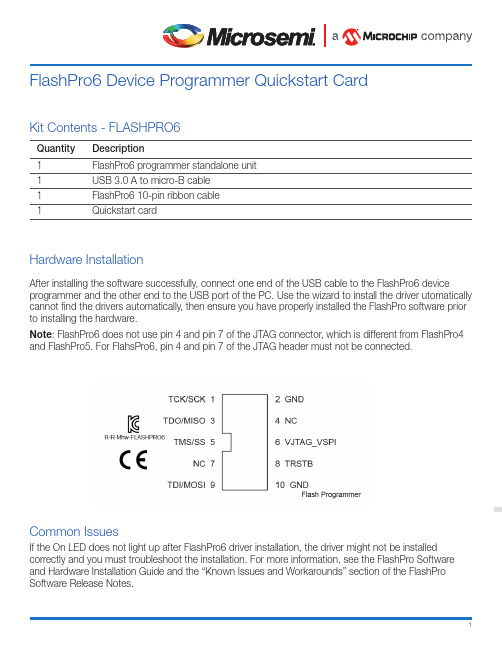
1Kit Contents - FLASHPRO6Quantity Description1FlashPro6 programmer standalone unit1USB 3.0 A to micro-B cable1FlashPro6 10-pin ribbon cable1Quickstart cardHardware InstallationAfter installing the software successfully, connect one end of the USB cable to the FlashPro6 deviceprogrammer and the other end to the USB port of the PC. Use the wizard to install the driver utomatically cannot find the drivers automatically, then ensure you have properly installed the FlashPro software prior to installing the hardware.Note : FlashPro6 does not use pin 4 and pin 7 of the JTAG connector, which is different from FlashPro4 and FlashPro5. For FlahsPro6, pin 4 and pin 7 of the JTAG header must not be connected.Common IssuesIf the On LED does not light up after FlashPro6 driver installation, the driver might not be installed correctly and you must troubleshoot the installation. For more information, see the FlashPro Software and Hardware Installation Guide and the “Known Issues and Workarounds” section of the FlashPro Software Release Notes.FlashPro6 Device Programmer Quickstart CardMicrosemi, a wholly owned subsidiary of Microchip Technology Inc. (Nasdaq: MCHP), offers a comprehensive portfolio of semiconductor and system solutions for aerospace & defense, communications, data center and industrial markets. Products include high-performance and radiation-hardened analog mixed-sig nal integ rated circuits, FPGAs, SoCs and ASICs; power manag ement products; timing and synchronization devices and precise time solutions, setting the world's standard for time; voice processing devices; RF solutions; discrete components; enterprise storage and communication solutions, security technologies and scalable anti-tamper products; Ethernet solutions; Power-over-Ethernet ICs and midspans; as well as custom design capabilities and services. Learn more at .Microsemi HeadquartersOne Enterprise, Aliso Viejo, CA 92656 USA Within the USA: +1 (800) 713-4113 Outside the USA: +1 (949) 380-6100 Sales: +1 (949) 380-6136Fax: +1 (949) 215-4996email:*************************** Microsemi makes no warranty, representation, or guarantee regarding the information contained herein or the suitability of its products and services for any particular purpose, nor does Microsemi assume any liability whatsoever arising out of the application or use of any product or circuit. The products sold hereunder and any other products sold by Microsemi have been subject to limited testing and should not be used in conjunction with mission-critical equipment or applications. Any performance specifications are believed to be reliable but are not verified, and Buyer must conduct and complete all performance and other testing of the products, alone and together with, or installed in, any end-products. Buyer shall not rely on any data and performance specifications or parameters provided by Microsemi. It is the Buyer’s responsibility to independently determine suitability of any products and to test and verify the same. The information provided by Microsemi hereunder is provided “as is, where is” and with all faults, and the entire risk associated with such information is entirely with the Buyer. Microsemi does not grant, explicitly or implicitly, to any party any patent rights, licenses, or any other IP rights, whether with regard to such information itself or anything described by such information. Information provided in this document is proprietary to Microsemi, and Microsemi reserves the right to make any changes to the information in this document or to any products and services at any time without notice.©2019 Microsemi, a wholly owned subsidiary of Microchip Technology Inc. All rights reserved. Microsemi and the Microsemi logo are registered trademarks of Microsemi Corporation. All other trademarks and service marks are the property of their respective owners.50200699 11/19https:///product-directory/design-resources/1750-libero-soc#downloads Documentation ResourcesFor more information about the FlashPro6 Device Programmer, see the documentation at https://www. /product-directory/programming/4977-flashpro#documents.SupportTechnical support is available online at https:///Portal/Default.aspx.Microsemi sales offices, including representatives and distributors are located worldwide. To find your local representative, go to /salescontacts。
APPRO宝马FEM BDC钥匙工具使用说明 V1
1.文档声明 (3)2、升级设备支持本功能 (4)2.1升级软件 (4)2.2检查授权 (5)2.3升级CODEBOX固件 (6)3、FEM/BDC控制单元编程 (6)第一步:OBD链接车辆/测试平台 (7)第二步:备份Coding数据(非常重要!!!) (9)第三步:模块编程 (10)3.1进入预处理EEPROM界面 (11)3.2拆卸FEM/BDC控制单元 (12)3.3拍照记录保险丝位置 (14)3.4拆95128/95256码片 (16)3.5编程器读取原始EEPROM数据 (17)3.6将新EEPROM数据写回95128/95256码片 (18)3.7升级FEM/BDC控制单元 (21)第四步:恢复原始EEPROM数据 (23)4、钥匙匹配 (27)第一步:获取车辆钥匙列表 (27)第二步:检测钥匙状态 (28)第三步:读取FEM/BDC密码 (31)第四步:生成新钥匙 (33)附录:FEM/BDC控制单元拆卸和安装说明 (38)APPRO宝马FEM/BDC钥匙工具使用说明2017年08月04日版本Ver1.01.文档声明请仔细阅读以下声明:✧宝马FEM/BDC钥匙工具说明文档仅限于辅助宝马FEM/BDC设备维修车辆,请遵守国家法律,勿用于违法用途。
✧非法使用本文档以及宝马FEM/BDC钥匙工具,由用户承担一切风险,本设备生产方不承担任何责任。
✧宝马FEM/BDC钥匙工具说明文档可以帮助您尽快学会使用宝马FEM/BDC钥匙工具,请仔细阅读。
APPRO宝马FEM/BDC钥匙工具使用说明2、升级设备支持本功能2.1升级软件图2.1.1软件版本信息2.2检查授权图2.2宝马FEM/BDC功能已授权2.3升级CODEBOX固件图2.3CODEBOX版本最低要求(0015版本) 3、FEM/BDC控制单元编程1.先择“钥匙工具”进入“宝马FEM/BDC”钥匙匹配功能图3.0宝马F系钥匙工具选项第一步:OBD链接车辆/测试平台1.打开电门后点击“链接车辆”按钮。
Control_M使用手册20130415资料
Control-M/Agent 向另一台未安装 Control-M/Agent 的应用服务器去下发作业。 由于 受网络以及用户的限制以及 Remote Host 无法加载功能模块, 所以使用起来相对没
Control-M/Agent 可安装在各种操作系统上, 并提供如 AFT(文件传输) ,DATABASE(S数
据库存储过程) , SAP( SAP软件相关)等功能模块方便不同的应用进行作业执行。
注:另外在 CONTROL-M/Server和 CONTROL-M/EM Server支持高可用,保障整个系统的 不受故障影响。
作业生命周期: 1. 作业在 Control-M/EM 提供的 GUI 界面中进行定义。 2. 作业提交到 Control-M/Server 进行调度。 3. Control-M/Server 将作业提交到所需执行的 Control-M/Agent 进行执行。 4. Control-M/Agent 将作业执行信息返回到 Control-M/Server 。
所以通过 Gateway 来处理 EM 具体和哪个 Control-M Server 通信。 Gateway 只负责管理 谁和谁通信,具体的通信是由 CMS 来处理。 Configuration Management Server ( CMS ) 与 Control-M Server 的 Configuration Agent 通信,通过它来处理管理员发布的请求。 Global Alerts Server ( GAS ) 管理报警信息给所有的 EM GUI 。 Global Conditions Server ( GCS) 发布全局条件给不同的 Control-M/Server 。 Batch Impact Manager ( BIM ) 进行关键作业进行提前告警。 Forecast Server 帮助查看未来某一天所需执行的作业。 Naming Service 用于提供 EM Server 对外的服务接口。 Configuration Agent 用于与 Control-M/Server 进行通信,下发作业调度指令。
XPM Operation Manual(Chinese)
授权服务机构
Vitronics-Soltec 服务地点如下:
我们每天提供 24 小时服务
请访问我们的网站: /
EM 02202-H NOVEMBER-2001
-3-
回焊炉操作,工艺参数和维护
*如何使用本手册*
本页解释手册的组织结构
主要部分(如目录所列)
次要部分(如目录所列)
本手册的通篇文本,你将发现下列惯例:
快速冷却 是选件,标题,或软件选择将用粗体大写显示. 回车是一键盘上的按键_将用粗体_大写显示.
很重要的信息被以下述方式显示:
1)粗体 2)大写 3)斜体 4)下划线 5)带阴影背景 6)用方框包围 7)使用 1-6 的组合
EM 02202-H NOVEMBER-2001
意义是相同的.
为回焊炉 测试温度曲线的热电 偶插口
急停按钮中断电源工作
回焊炉上盖升起和下落转 换开关
调整轨道和中心可折叠支撑 装置进入或外出的转换开关
EM 02202-H NOVEMBER-2001
-5-
回焊炉操作,工艺参数和维护
定义
下列术语被定义为: 加热单元:在许多回焊炉上的上面或下部半个加热(或冷却)单元,例如:上温区,冷却温区等等. 点击:把鼠标的指针置于选择点并且按下适当开关的动作. 控制系统:操作回焊炉综合了电子,机械,计算机和软件系统各个方面的要求. 对话框:在屏幕上可输入信息的小窗口. 图标:一个项目,操作,或功能的图形表示(标志),一些图标能被指标选择. 菜单:
回焊炉控制软件
软件版本 7。04。00。XX 下拉菜单扩展图在第 7 页显示 介绍………………………………………………………………….…………………………………………………2 *如何使用手册*……………………………………….………………………………………………….. .4 回焊炉控制面板按钮符号…………………………….……………………………………………………5 定义……………………………………….…………………………………………………………………6 操作屏幕_菜单_对话框_符号………………….…………………………………………………….…………...7 下拉菜单(可得到“帮助”)………………….…………………………………………….…………....8 回焊炉状态条(位于在屏幕底部)…………….…………………………………………….…………....8 口令登入/退出…………….……………………………………………………………….………………...9 口令控制(全局口令需求)…………….…………………………………………….……………....…..10 口令权限(用户进入允许)…………….………………………………………….………………..........11 图标(屏幕图形标志)…………….…………………………………………….…………………...…...12 打印…………….…………………………………………………………………….………………...…...14 自动开机/关机…………….………………………………………………………….……………..…...…15 传输链速度与温度的在线编辑…………….…………………………………….……………..……...….18 生产对象与工艺参数…………….……………………………………………………….….…………….…………19 生产对象和工艺参数的解释…………….……………………………………….…………………….….19 编辑一个生产对象工艺参数(包括:拷贝,新增_编辑_或删除)………………………….….…..20 生产对象术语及其定义…………….…………………………………………………………….…….….22 工艺参数术语及其定义…………….…………………………………………………………….….….…22 选择和开启一个流程(生产对象或 工艺参数)…………….………………………………….…….…23 回焊炉状态警报_警告_与关机…………….……………………………………………………………….….…24 警报/事件讯息…………….…………………………………………………………………….….………29 警报级别及其设定…………….………………………………………………………………..………….30 回炉特征和选件…………….…………………………………………………………………….……..……………31 轨道宽度 调整…………….………………………………………………………………..………………31 数据记录…………….……………………………………………………………………..……………….33 板的追踪_跌落与轧住…………….……………………………...……………………..………………..34 快速冷却…………….…………………………………………………………………….……….……….35 温度曲线…………….………………………………………………………………….……….………….36 轨道链润滑…………….……………………………………………………………….……….………….39 调整/编辑操作参数及其缺省值…………….………………………………………………….………….………...42 传输链速度校准…………….……………………………………………………….……….………….....42 自动轨道宽度校准…………….…………………………………………………….……….………..…...45 测试回焊炉温度曲线…………….…………………………………………………………….………….….………47 总述…………….………………………………………………………………….………….…………….47 测试温度曲线目的…………….………………………………………………….…….………………….47 测试温度曲线选择 KIC,ECD,或机器本身程序…………….…………….…….…………….…....48 使用“How do I”得到帮助…………….……………………………………….…….……………..…....49 为测试温度曲线 准备 热电偶 与 印刷电路板…………….……………………….….……………….....50 测绘温度曲线…………….……………………………………………………….….………………….....55 快速开机指南…………….……………………………………………………………….…….……………..…..….59 使用排除故障程序…………….…………………………………………………….….………………………….…62 回焊炉配置(检查各种设定)…………….……………………………….…………………………..…62 测试子系统 设备…………….…………………………………………….………………………….……68 强制数字式输出…………….…………………………………………….………………………….…….69 检查数字式输入状态…………….…………………………………….…………………………….…….70 检查数字式输出状态…………….…………………………………….…………………………….…….71 维护…………….………………………………………………………………….…………………………….……72 推荐计划表与时间要求…………….……………………………………………………………….….….72 维护程序…………….…………………………………………………………………………………..….73 索引…………….………………………………………………………………………………………………..…….91
PGM操作说明书(明细)

◆PGM系统概述:(需一天时间)●操作界面介绍:拷频整个操作界面(标注说明:下拉式菜单、工具栏、纸样栏、辅助工具栏、操作区域)●工具条选择(显示或隐藏工具条): 1. 通过在工具条界面点击鼠标右键—自定义(TOOLBARS) 2. 视图—工具栏●工具条摆放: 按住鼠标左键拖动工具条前的双杠边把工具条摆放到操作人员较顺手的位置●工具条中某个工具的显示或隐藏: 在工具条界面点击鼠标右键—自定(工具) 可将工具条中不常用的工具拖入其中,扩大操作区域●单位名称设置: 选项----设定单位(厘米、英寸误差调整)●操作界面中文字设置: 选项----字型(屏幕、内部文字、纸样栏、纸样排栏轮廓、打印机)●版面颜色及线种类调整:选项----颜色----颜色及线种类(一般颜色栏目)●操作前相关知识了解(以表格形式说明):◆PGM打版系统:(需七天时间)●以男衬衫为例:建立基础框架:编辑----新建纸样----新建矩形、线段加点、移动点、多个移动、圆、辅助线利用以上工具变化出不同的打板方式:前后片分开打法(主要体现工具的灵活性)前后片重叠打法前后片并列打法通过前后片的各种打法引申出:不同肩斜制法的工具灵活使用:定数肩斜角度肩斜比例肩斜定小肩宽不同袖窿深制法的工具灵活使用:以上平线定袖窿深以肩斜线定袖窿深以肩斜点定斜跨肩放码基础工具:建立放码档数(放码----尺码)、显示放码表、选放码点后填放码数值、复制黏贴放码数值(几种黏贴方式)、放完基础码用排点工具查看板型各部位效果缝份基础工具:加整体缝份、修改单边缝份、缝份折边处理●以外销裤为例:建立基础框架:(以上建框架所用到的工具)、线段等份(编辑----加入----加点/线与线上)、空间等分(钮位距离)、修改锁定弧线长度(MEASURE测量工具)、延伸轮廓放码基础工具:(以上所用到的基本放码工具)、制作放码表库缝份基础工具:(以上用到的缝份工具)、单边变量缝份(后浪处理)死褶基础工具:建立死褶、死褶放码、合并死褶●以开公主线女上装为例:建立基础框架:(以上建框架所用到的工具)、公主线开刀(画笔工具、裁剪工具)放码基础工具:(以上所用到的基本放码工具)、内部如口袋、腰省等推挡(比例放码)缝份基础工具:(以上用到的缝份工具)、单边缝份处理(折角、剪角)死褶工具:建立死褶、死褶(褶尖、褶量)转移多种配领、配袖方式:(结合教学过程中遇到的不同人的打法来找相应的工具)●以插肩袖为例:建立基础框架:(以上建框架所用到的工具)、辅助线(做斜度辅助线垂直)、线条复制及调整(编辑----线段----复制)放码基础工具:(以上所用到的基本放码工具)、角度放码工具缝份基础工具:(以上用到的缝份工具)附助工具:行走工具(对位标记)、连接纸样工具修改工具:制作布纹线(平行布纹线、角度布纹线、旋转布纹线)●以完整的男西服为例(将之前的所有工具进行串联):建立基础框架:(以上建框架所用到的工具)放码基础工具:(以上所用到的基本放码工具)、号型放码缝份基础工具:(以上用到的缝份工具)、缝份开叉、开叉倒角(裁剪缝份角度)◆PGM特殊(优秀)工具:(需三天时间)●放码工具:树放码(以内衣板为例)●用编辑工具手工放码:(弧线造型单段调整)●死褶与生褶的多种变化:加容位(立体袋)(袖肘省)(膝盖省)、多个死褶(前中有褶)(不对称省道)(泡泡袖)、生褶(百褶裙)(鱼尾裙)(羊腿袖)、生褶线(不同类型不同深度的褶同时制作)●加放缩率(缩率回退):纸样----修改----比例缩放(样版缩率、单线条缩率、缩率以文字说明)、缩率回退公式●牙口设置:牙口推挡变化(按比例推挡、按定数推挡)●比较线段长度:多条线段累加,累减(查看各段或多段线段弧线长度或直线长度)●纸样库:将基本款式轮廓做好存入纸样库中,以后可当工具直接调用◆PGM软件中各项菜单栏下的设置:(需两天时间)文件----合并设计文件、文件----文件效用----打开备份文件、纸样----总体资料、纸样----一般----总体修改内部、纸样----一般----总体牙口放码、纸样----一般----加入支持曲线点、纸样----清除多余点、设计----剪裁、设计----孔洞入纸样/纸样向孔洞、设计----点连接、设计----相等线段、设计----安排绘图、视图----显示纸样内容、视图----一般选项、视图----纸样、视图----提示资料、选项----抓取、选项----痕迹线、选项----移动对话盒、选项----其余设定◆PGM描版系统:(需一天时间)●数字化仪设定:设定读图板(每项内容具体含义)截图后标注说明●描基本码:描版方式(16键定位器描版时的按键含义)、修版(旋转、修线、修点)图例说明●描全码版:建立尺码(基码设定为最小码或最大码)、描版方式图例说明◆PGM排料系统:(需三天时间)●多种铺布方式与排料区域设置的关系:排料图定义(排料图面积、层数、排料图布料、带剩余部分的排料图面积)截图后标注说明●排料样板文件的调取:选择设计文件(浏览找排料文件、设定捆扎数量、查看纸样资料)截图后标注说明●排料区样板的调整工具:样板放置、重叠样板、旋转样版、滑动靠齐样板●排料区的变化:复制排料图(手枪型排料)、交替样片(更新设计文件、排料图----替代)、编辑样片(纸样----编辑纸样)●特殊排料方式:对格对条(排料图----条纹及布纹)、毛皮类排料(纸样----建立新纸样)、色差排料(排料图----裂缝)、捆绑(配套----捆扎)●特殊工具:(套排NEST++、自动排队排图、报告于EXCEL、运算成本)●排料界面中各项菜单栏下的设置:文件----合并排料图文件、纸样----内部----总体内部参数、排料图----侦察内部重叠、视图----纸样于排料图上内容、视图----提示资料、选项----其余设定◆PGM转换资料系统:(需一天时间)●●●◆PGM打印系统:(需一天时间)●一比一输出:各款打印的连接设置、打版系统/排料系统分别打印方式(文件----绘图)●缩小比例打印:文件----绘图----更多、文件----打印●截图拷频打印:。
FLEX 5000 安全頻率輸入模組 使用手冊说明书

FLEX 5000 安全頻率輸入模組型號 5094-IJ2IS、5094-IJ2ISXT2Rockwell Automation 出版物 5094-UM004A-ZC-P - 2021 年11 月FLEX 5000 安全頻率輸入模組使用手冊使用者重要資訊進⾏本產品的安裝、設定、操作或維護前,請閱讀本文件及其他資源一節內有關本設備安裝、設定和操作的文件。
使用者除了必須瞭解所有相關法規、法律條文與標準外,還需熟知安裝與配線說明。
舉凡安裝、調整、運作、使用、組裝、拆卸及維護等作業,均需由受訓合格的⼈員依照相關法規進⾏。
若以製造商未提及之方式使用本設備,將可能損害到製造商為本設備所提供的保護措施。
不論任何情況,Rockwell Automation Inc. 對於使用或應用此裝置而產生的間接或連帶損壞,均不負擔任何法律或賠償責任。
本⼿冊中的範例和圖表皆僅供說明之用。
由於個別安裝會有許多不同的變數及條件,Rockwell Automation, Inc. 無法對依照範例及圖⽰指⽰進⾏的實際使用狀況負責或提供賠償。
關於本⼿冊中所述之資訊、電路、設備或軟體部分,Rockwell Automation Inc. 概不承擔任何專利責任。
在取得 Rockwell Automation Inc. 書面同意之前,禁止重製本⼿冊部分或全部內容。
在整本⼿冊中,我們會在必要時使用註記,讓您瞭解安全注意事項。
這些標籤也可能位在設備上方或內側,以提供特定預防措施資訊。
以下圖⽰可能會出現在本文件的文字中。
Rockwell Automation 瞭解本出版物及業界目前所使用的部分詞彙,並不符合技術中包容性語⾔的發展趨勢。
我們正積極與業界同仁合作,找出這類詞彙的替代方案,並對產品和內容進⾏變更。
在我們實施這些變更時,請原諒我們在內容中使用此類詞彙。
警告:指出可能在危險環境中導致爆炸的做法或情況之相關資訊,爆炸可能會進而導致⼈員受傷或死亡、財物損失或經濟損失。
超越宝典汽配汽修管理系统操作说明书
超越宝典汽配汽修管理系统操作说明书一维修业务 (4)A: 前台管理 (4)B:车间管理 (9)C:工单浏览 (12)D:三包索赔 (13)1.索赔管理 (13)2.索赔工时报表 (14)3.索赔配件报表 (14)4.索赔车辆报表 (14)二美容管理: (15)A:精品入库 (15)B:精品出库 (15)C:服务项目定义 (15)D:会员卡定义 (15)E:会员卡管理 (15)F:美容服务 (15)G:本地参数设置 (16)三配件业务: (16)A:商品销售 (16)B:销售退货 (18)C:维修领料 (18)E:其它出库 (19)F:调拨出库 (19)G:销售报价 (20)I:商品入库 (20)J:入库退货 (22)K:订货管理 (23)1.订单制作 (23)2.订单合同 (24)L:需求管理 (25)M:库存管理 (27)1.库存浏览 (27)2.库存修改 (27)3.库存盈亏 (29)4.库存盘点 (31)5.库存处理 (31)N:库存月结 (32)四决策分析: (32)A:出库查询 (32)2.维修领料查询3.调拨出库查询4.其它出库查询5.销售报价查询 (33)B:入库查询 (33)C:库存查询 (34)D:盈亏查询 (34)E:库存超储或缺货查询 (34)F:进出流水帐查询 (34)G:进销存查询 (34)H:维修统计 (35)1.进厂台次统计 (35)2.返修率统计 (36)3.当日交车率统计 (36)4.计划内交车率统计 (36)I:维修报表 (36)1.维修业务报表 (36)2.结算车辆明细报表 (36)3.结算车辆汇总报表 (37)4.维修工时清单 (37)5.班组业绩报表 (37)J:日营业统计 (38)K:日营业查询 (38)L:月销售统计 (38)M:月销售查询 (38)N:服务质量与提醒 (39)1.待年审客户提醒 (39)2.服务卡到期提醒 (40)3.客户流失率统计 (40)O:自定义查询 (40)P:自定义统计 (40)五基础资料: (41)A:零件属性: (41)B:互换编码定义 (43)C:安全库存设置 (43)D:客户档案 (45)E:供应商档案 (45)F:车辆档案 (46)G:维修项目 (47)H:车类工时单价 (48)I:故障项目设置 (48)J:附加项目 (49)K:辅助资料 (49)六短信管理: (50)A:自动提醒 (50)B:备忘短信 (50)C:自由短信 (51)D:短信历史 (52)1.用户参数设置 (53)2.短信用语设置 (53)3.节日短信用语设置 (53)F:短信帐户管理 (54)1.帐户注册 (54)2.帐户充值 (54)3.余额查询 (54)七系统管理: (54)A:权限设置 (54)B:参数设置 (55)C:功能密码 (55)D:数据初始化 (55)E:单号初始化 (56)F:系统运行跟踪 (56)G:旧系统数据转入 (57)H:拼音五笔代码 (57)I:自定义查询报表 (58)J:帐套管理 (58)K:备份帐套 (58)L:恢复帐套 (58)M:操作密码修改 (59)N:登陆系统 (60)八财务结算 (60)A:维修业务结算: (60)1.维修收银 (60)2.收维修欠款 (60)3:保险索赔结算: (61)4:原厂索赔结算: (61)B:配件业务结算: (61)C:未结清单据对帐: (61)D:应收、付帐管理: (62)九财务 (62)A:基本资料 (64)1:会计科目 (65)2:币种设置 (68)3:结算方式 (68)4:凭证摘要 (68)B:凭证管理 (68)1:手工凭证处理 (68)2:业务凭证管理 (70)3:凭证登帐 (72)4:凭证查找 (72)5:结转损益 (74)6:期末结算: (75)7:年度转帐: (75)1:总分类帐 (76)2:明细分类帐 (78)3:科目汇总表 (79)4:试算平衡表 (80)5:数量金额总帐 (81)D:分类帐 (81)1:部门分类帐 (81)2:项目/员工/往来单位分类帐 (81)E:财务报表: (82)1:自定义报表 (82)2:现金流量表 (84)2、现金流量初始数据 (85)3、现金流量数据准备 (85)F:应收应付管理 (88)G:出纳帐管理 (89)H:辅助工具 (90)一维修业务A:前台管理功能介绍、及操作步骤: 点击【维修业务】-【前台管理】。
COREMIX30操作手册-中文版

均质机2 操作手册均质机操作手册3亲爱的顾客我们很高兴您选择了一件优质产品它能满足您的需要感谢您选择我们我们高兴邀请您在操作新机器前阅读我们的操作手册目录警告普通/机械危险高压危险高温危险手册中以上两个标记后的操作指示请您严格遵守,以避免对人身造成伤害。
请您注意该标识后的使用事项,以避免机器受损、出现故障或性能降低。
均 质机4操作手册1安全操作注意事项在安装和运行机器前请仔细阅读操作手册里所包含的指令。
这些指令是专门为机器的安全安装,运行及维护所设计的。
■ 操作指示手册臵于包装箱内的机器上,并有技术手册为支持补充。
欧盟认证的合格证和机器电器性能测试表(同样定义,在该运行指示手册上,简单的周期,机器)而且必须妥善保存以应付将来的咨询。
■ 机器出现故障时必须将本技术手册交给专职服务人员。
■ 产品销售或运送给其他使用者,必须交给新用户。
小心高温:在杀菌过程中,原料会变得很热(+65…+90˚C )。
触摸塑料盖[5]出料阀[11]和机器表面会导致严重的伤害。
当LID (塑料盖)被打开的时候,原料温度非常高。
请遵守以下条例:■ 每次都要检查循环杀菌是否完成以及原料温度,在陈列和展示的时候,必须十分缓慢的打开塑料或出料阀。
■ 注意在消毒循环的过程中如果出现中断电源故障,原料的温度仍旧会很高,但机器的温度计却无法显示。
■ 如果怀疑原料的温度太低,如无绝对必要,不要打开塑料盖或出料阀。
如确有必要应做好各项防护工作,避免与原料发生接触。
不要把手指或其他物品伸入机器的出料口。
不要撕毁或覆盖机器上的所有标签。
严禁自行拆卸机器。
用户必须严格遵守操作手册的要求,在机器上使用其它非配套的操作工具必须由专职服务人员进行。
■ 操作机器上可拆卸部件时必须切断电源。
■ 改变机器的供电规格(电压和频率)必须由专职服务人员进行。
■ 此机器仅用于均质、巴氏消毒。
■ 部件不齐禁止使用机器。
■ 该机器是自动运行的,严禁儿童接触。
■ 严禁私自改装机器,引起意外后果自负。
最先进的设备编程器用户指南说明书

USER GUIDE(Revision 1.04)Micro-Pro User Guide V1.04Information in this document is subject to change without notice and does not represent a commitment on the part of the manufacturer. The software described in this document is furnished under license agreement or nondisclosure agreement and may be used or copied only in accordance with the terms of the agreement.It is against the law to copy the software on any medium except as specifically allowed in the license or nondisclosure agreement.The purchaser may make one copy of the software for backup purposes. No part of this manual may be reproduced or transmitted in any form or by any means, electronic, mechanical, including photocopying, recording, or information retrieval systems, for any purpose other than for the purchaser’s personal use, without written permission.Copyright Information(C) 1994-1997 Copyright Equinox Technologies. All rights reserved.Atmel TM and AVR TM are trademarks of the Atmel CorporationKeil C51TM and dScope TM are trademarks of Keil Elektronik GmbHMicrosoft, MS-DOS, Windows TM and Windows 95TM are registered trademarks ofthe Microsoft CorporationIBM, PC and PS/2 are registered trademarks of International Business Machines Corporation Intel, MCS 51, ASM-51 and PL/M-51 are registered trademarks of the Intel Corporation Every effort was made to ensure accuracy in this manual and to give appropriate credit to persons, companies and trademarks referenced herein.ContactsEquinox Technologies UK Limited 3 Atlas House, St Georges Square, Bolton, England BL1 2HBTelephone Sales .......................:+44 (0) 1204 529000Fax ..............................................:+44 (0) 1204 535555E-mail .........................................: **********************Web site ....................................: For technical support on this product please e-mail us at:*************************Software UpdatesIn line with our policy of continuous improvement, the ‘Meridian for Windows™’ software is updated on a regular basis. If you would like to receive an automatic e-mail every time a new version is released, please make sure you have registered your system with Equinox and you have quoted your e-mail address. You may cancel this service at any time.The Meridian software updates can currently be downloaded from the following places:Internet:ftp site:Atmel BBS:+1 408 436-4309ContentsINTRODUCTION (1)SYSTEM SPECIFICATIONS (2)INSTALLATION OVERVIEW (3)HARDWARE INSTALLATION INSTRUCTIONS (4)SOFTWARE INSTALLATION (5)PARALLEL PORT SELECTION (6)HARDWARE OVERVIEW (7)SOFTWARE OVERVIEW (8)DEVICE SELECTION (10)DEVICE POSITION & ORIENTATION (11)DEVICE SUPPORT (12)8051 SUPPORT PRODUCTS GUIDE (14)AVR SUPPORT PRODUCTS GUIDE (15)MISCELLANEOUS ACCESSORIES (16)Micro-Pro User Guide V1.04he Micro-Pro is a state-of-the-artdevice programmer supporting a wide range of programmable devices. The programmer was originally developed to program the Atmel AT89C and AT89S microcontroller families, but support has now been widened to include many other 8051 derivatives and also a selection of popular Atmel FLASH and EEPROM memories.The Micro-Pro programmer features extremely fast programming speeds due to its optimised field-programmable hardware. Further speed enhancements have been made possible by virtue of the parallel data connection to the PC. The powerfulfront-end software caters for both involved development cycle programming needs and production batch programming requirements.MICRO-PRO DEVICE PROGRAMMER HIGHLIGHTS•State-of-the-art Device Programmer •Supports the entire Atmel 89C & 89Smicrocontroller families as standard •Supports many generic 8051 devices(87C51-FA/FB/FC)•Supports many Atmel AVRmicrocontroller derivatives•Also supports many Atmel FLASH,EEPROM and Configurator devices •Field Programmable hardware ensuresfuture device support•FAST programming times due tooptimised hardware/softwarealgorithm for each device•Device Manufacturer Certification formany algorithms•Supports most DIL devices up to 40pins without an adaptor •Adaptors available for many otherpackage types•Connects to spare PC parallel port •Straightforward hardware/softwareinstallation•Supports programming of securitylock bits security tables and specialoption bitsIntroduction TMicro-Pro User Guide V1.04 System SpecificationsMINIMUM SYSTEM CONTENTSMicro-Pro Device ProgrammerPower Supply (PSU)Parallel Cable (25w M/M pin to pin) MICRO-PRO PARALLEL PROGRAMMER SPECIFICATIONS Programmer Size:10.5 x 8 x 2 cm Shipped Weight:approx 1.5kgPSU:15V DC @250mA Port connection:Parallel 25-way DZIF socket:Quality 40way socketAccepts both 0.3/0.6”pitch devices MINIMUM PC REQUIREMENTSThe minimum hardware and software requirements to ensure that the programmer operates correctly are as follows:100% IBM compatible 386+ Windows 3.1 or higherMinimum 4MB RAMMinimum 1MB free hard disk space Spare PC parallel portMicro-Pro User Guide V1.04Installation OverviewThe Hardware/Software Overview for the installation process of the Micro-Pro programmer is detailed diagrammatically below. Please refer to the following pages for a more detailed explanation.Micro-Pro User Guide V1.04Hardware Installation Instructions OVERVIEWThe Micro-Pro programmer connects to any spare PC parallel(LPT) port. If you only have one parallel port and this is in use for eg. a printer, it may be possible to add a second parallel port to your machine by inserting a new I/O card. If you are limited to one parallel port eg. on a laptop, then it is necessary to remove any other devices connected to that parallel port for the duration of using the Micro-Pro.For further hardware installation help, please refer to the Installation Troubleshooting Guide.Connect the programmer to the PC as follows:1Plug male end of PC parallel cable into spare PC parallel port2Plug female end of PC parallel cable into 25-way connector on the programmer3Plug power jack into programmer4Plug mains adaptor into suitable mains supplyThe programmer RED ‘POWER’ LED should now be illuminatedMicro-Pro User Guide V1.04The Micro-Pro programmer is supplied with 'Micro-Pro for Windows' PC driver software. This software is supplied on one 3.5" floppy disk.TO INSTALL 'MICRO-PRO FOR WINDOWS' SOFTWARE:•Boot the PC into Windows environment (Win 3.1 or Win 95 )•Insert 'Micro-Pro for Windows' disk into floppy disk drive (A: / B:)•Select the 'Run...' command from the'File' menu in the Program Manager •Select 'Browse' and navigate to the floppy drive (A: / B:)•Select 'micropro.exe'•Select the 'OK' buttonThe software installation program should now display an introductory screen. Please follow the on-screen prompts in order to complete the software installation process.For more detailed information on which libraries to install, please refer to the ‘Device Support’ section.On completion, the installation program will install the 'Micro-Pro' icon within a new program group called 'Micro-Pro'.To launch the software, simplydouble-click on the'Micro-Pro' icon.Software InstallationMicro-Pro User Guide V1.04The Micro-Pro programmer plugs into a spare parallel port of any IBM compatible PC including the majority of laptop machines.The programmer should operate correctly in the following parallel port (LPT) modes:i.Uni-directional modeii.Bi-directional (Enhanced or EPP) mode However, if the programmer fails to be detected it is worth switching the LPT mode between uni and bi-directional using the PC bios and then re-trying the communication test.TO SELECT THE CORRECT PARALLEL PORT (LPT):i.From the menu bar select <Options><Select Port>The available LPT ports on your computer together with the corresponding address are now displayed. eg. LPT1 ($378)If you have more than one parallel port on your PC, but only one LPT address is displayed, it is likely that your hardware setup requires adjusting in the PC bios.ii.Select the LPT port to which the programmer is connectediii.Select <Test>A programmer communications test is now performed.This tests both the programmer, cable and PC parallel port. COMMUNICATIONS TEST PASSThe programmer has been detected OK by the Micro-Pro software. If you now<Cancel> out of the <Test Port> dialogue box, the words ‘ON LINE’ should now be displayed at the bottom right of the Micro-Pro Window.Installation is complete and the programmer should now be ready to-use. COMMUNICATIONS TEST FAILThe programmer was not detected on the LPT port selected. Please check that the correct LPT port was selected, and if not, repeat the <Select Port> < Test> operation. If the programmer is still not detected, please refer to the Installation Troubleshooting Guide located in the help file on disk.Parallel Port Selection (Select Port)Hardware Overview273Key1PSU input2Parallel cable connection (to PC)3ZIF (Zero Insertion Force) socket (40 way)4Auxiliary power connector5Power LED (Red)6Active LED (Yellow)7Atmel AT6002 FPGABLANK CHECKChecks if the currently selected device is blank.i.e. All locations = FFhSoftware OverviewSAVE TO DISK (Ctrl + S)Allows you to save the contents of the buffer(s) to a file.Currently supports Intel Hex and Binary file formats as standard.The Micro-Pro for Windows software features many powerful functions which can be activated by simply clicking a single icon. Other utilities and commands are available by selecting the relevant menu option.For further information about the Micro-Pro for Windows software , please refer to the 'On-line Help System' supplied with the software.The most commonly used functions for which an icon exits are listed below.Software Overview continuedERASE DEVICEPerforms an ELECTRONIC erase on the currently selected device.Please note: OTP and EPROM devices do not support anELECTRONIC erase cycle.It is necessary to select the particular device to be programmed as follows:e.g. To select the Atmel AT89S8252 microcontroller as the current device Device Selection2You will now be presented with a list of device types Choose MICROCONTROLLER1Select the DEVICE menu and choose SELECT3 A list of device manufacturers is now displayed Select the one you require i.e. Atmel4 A list of microcontroller devices produced by that manufacturer is now displayed.Select the one you require i.e. AT89S8252The currently selected device is now activeDevice Position & OrientationThe Micro-Pro programmer accepts a wide variety of devices in dual-in-line (DIL) packages without the need for additional package adaptors or convertors. The Zero Insertion Force (ZIF) socket caters for DIL device with up to 40 pins and can also accept both 0.3” and 0.6”pitch devices.The diagram below shows the correct position and orientation of the target device in the ZIF socket. The position of pin 1 of the target device is marked by a dot.Device Position & Orientation Key1MICROCONTROLLER (40 pin - 0.6” pitch)e.g. 89C51, 87C522FLASH (32 pin - 0.6” pitch)e.g. AT29C512, AT29C010PARALLEL EEPROM (32 pin)e.g. 28C5123MICROCONTROLLER (20 pin - 0.3” pitch)e.g. AT89C2051, AT90S12004SERIAL EEPROM (8 pin - 0.3” pitch)e.g. AT24C08, AT250105SERIAL CONFIGURATORS (8 pin - 0.3” pitch)e.g. 17C256Device SupportATMEL89C Microcontroller AT89C5189C Microcontroller AT89C5289C Microcontroller AT89C5589C Microcontroller AT89LV5189C Microcontroller AT89LV5289C Microcontroller AT89LV5589C Microcontroller AT89C51-xxxx-589C Microcontroller AT89C52-xxxx-589C Microcontroller AT89C55-xxxx-589C Microcontroller AT89LV51-xxxx-589C Microcontroller AT89LV52-xxxx-589C Microcontroller AT89LV55-xxxx-589C Microcontroller AT87F5189C Microcontroller AT87F5289C Microcontroller AT89C105189C Microcontroller AT89C1051U 89C Microcontroller AT89C205189C Microcontroller AT89C405189S Microcontroller AT89S825289S Microcontroller AT89S5389S Microcontroller AT89LS825289S Microcontroller AT89LS53EEPROM Memory AT28C010-DIL32EEPROM Memory AT28C010E -DIL32EEPROM Memory AT28C010-PLCC32EEPROM Memory AT28C010E -PLCC32EEPROM Memory AT28C16-PLCC32EEPROM Memory AT28C16E -PLCC32EEPROM Memory *AT28C17-PLCC32EEPROM Memory AT28C17E -PLCC32EEPROM Memory *AT28C64-PLCC32EEPROM Memory *AT28C64E -PLCC32EEPROM Memory *AT28C64X -PLCC32EEPROM Memory *AT28C64B -PLCC32EEPROM Memory *AT28HC64B -PLCC32EEPROM Memory *AT28C256-PLCC32EEPROM Memory *AT28HC256-PLCC32EEPROM Memory *AT28C256E -PLCC32EEPROM MemoryAT28C040-44PLCCTypeDeviceFPGA Configurator AT17C65DIP8FPGA Configurator AT17C128DIP8FPGA Configurator AT17C256DIP8FPGA Configurator AT17C65SOIC20/PLCC FPGA Configurator AT17C128SOIC20/PLCC FPGA Configurator AT17C256SOIC20/PLCC Flash Memory *AT29C256-DIL28 NEED Flash Memory AT29C256-PLCC32Flash Memory *AT29C257-PLCC32Flash Memory AT29C512Flash Memory AT29C010Flash Memory AT29C010A Flash Memory AT29C020Flash Memory AT29C040A Flash Memory AT49F010Flash Memory AT49F020Flash Memory AT49F040Serial EEPROM AT24C01Serial EEPROM AT24C01A Serial EEPROM AT24C02Serial EEPROM AT24C04Serial EEPROM AT24C08Serial EEPROM AT24C16Serial EEPROM AT24C164Serial EEPROM AT24C32Serial EEPROM AT24C64Serial EEPROM AT24C32SOIC14Serial EEPROM AT24C64 SOIC14Serial EEPROM AT25010Serial EEPROM AT25020Serial EEPROM AT25040Serial EEPROM AT93C46Serial EEPROM AT93C56Serial EEPROM AT93C57 Serial EEPROM AT93C66AVR Microcontroller AT90S1200AVR Microcontroller AT90S1200A AVR Microcontroller AT90S2313AVR Microcontroller AT90S8515-SPI ¦AVR MicrocontrollerAT90S4414-SPI ¦* Please note:The following 28-pin FLASH &EEPROM devices can only be supported in PLCC-32 package. The DIL-28package can not be supported.¦ Only Serial (ISP) programming mode is supportedINTELType Device Microcontroller80C251SB Microcontroller87C251SB Microcontroller D87C51-2 Microcontroller D87C51 Microcontroller D87C51OTP Microcontroller D87C51BH OTP Microcontroller D87C52 Microcontroller D87C52OTP Microcontroller D87C52BH Microcontroller D87C51FA Microcontroller D87C51FA OTP Microcontroller MR87C51/B Microcontroller D87C51FB Microcontroller D87C51FB OTP Microcontroller D87C54OTP Microcontroller D87C51B OTPPHILIPS/SIGNETICSType Device Microcontroller SC87C51 Microcontroller SC87C51OTP Microcontroller SC87C52OTP Microcontroller S87C51FA Microcontroller S87C51FB Microcontroller S87C51FC Microcontroller 87C52EBPN OTP Microcontroller87C52EPFFA Microcontroller S87C51CCN40OTP Microcontroller S87C51 FB-4F40OTP Microcontroller S87C51CCF40OTP TEMICType Device Microcontroller87C251SBDevice Support continuedDALLASType Device Microcontroller DS87C5208051 Support Products GuideAVR Support Products GuideMiscellaneous AccessoriesCablesCAB-PAR25MMPC Parallel Cable (25W to 25W M/M 2M)Power SuppliesPSU-15250-UK, PSU-15250-US, PSU-15250-EUMains Power Supply Adaptor 15V@250mASuitable for use with:Micro-PRO ProgrammerActiv8r Programmer Adaptors20-pin SOICadaptorillustratedPin 144-pin PLCCadaptorillustratedEquinox Technologies UK Limited reserves the right to change any information contained withinthis manual without prior notice. E&OETerms and product names contained in this document may be trademarks of others.。
PACSystems RX3i PROFIBUS Master模块用户手册说明书
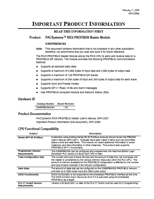
February 11, 2005GFK-2359AI MPORTANT P RODUCT I NFORMATIONREAD THIS INFORMATION FIRSTProduct: PACSystems™ RX3i PROFIBUS Master ModuleIC695PBM300-BANote: This document contains information that is not available in any other publication;therefore, we recommend that you read and save it for future reference.The RX3i PROFIBUS Master Module allows the RX3i CPU to send and receive data on aPROFIBUS-DP network. The module provides the following PROFIBUS communicationsfeatures:Supports all standard data ratesSupports a maximum of 3,584 bytes of input data and 3,584 bytes of output dataSupports a maximum of 125 PROFIBUS-DP slavesSupports a maximum of 244 bytes of input and 244 bytes of output data for each slaveSupports Sync and Freeze modesSupports DP-V1 Read, Write and Alarm messagesHas PROFIBUS-compliant Module and Network Status LEDsHardware IDCatalog Number Board RevisionIC695PBM300-BA 1.00Product DocumentationPACSystems RX3i PROFIBUS Master User’s Manual, GFK-2301Important Product Information (this document), GFK-2359CPU Functional CompatibilitySubject Description Series 90 -30 Profibus Customers using existing Series 90-30 Profibus products should review the PBM300User’s Manual (GFK-2301). Changes have been made in items such as CommReqstatus words and data fields. This module will report additional information in someinstances, and less information in other instances. This product also supportsPROFIBUS DP-V1 functionality.Programmer Version Requirements The IC695PBM300 can be configured and programmed with Machine Edition Logic Developer PLC version 5.0 Build 3227 SP2 or later.Total Configuration Size The number and type of slave devices and the amount of data they can exchange withthe master is constrained by the various memory resources within the PLC CPU. Theamount of memory available for the PROFIBUS configuration is affected by the numberand type of slave modules in the network configuration.Data Sizes The amount of data that can be configured on the IC695PBM300 PROFIBUS networkprovides up to 3584 bytes input and 3584 bytes output.DOIO Functionality DOIO functionality is not supported to the embedded PROFIBUS interface at this time.The DOIO function block returns an error if it is executed using the embeddedPROFIBUS as a target.PLC C Toolkit VersionRequirementsVersion 4.00 Build 50A1 or later of the PLC C Toolkit must be used for C programming.2 Important Product InformationGFK-2359APBM300 Restrictions and Open IssuesSubject DescriptionGet Master Status CommReq returns “1 or More Slaves Not in IO Exchange Mode” on First Scan When a Get Master Status CommReq is called on the first scan of the PLC, the CommReq may return a false positive saying that the Profibus network has “1 or More Slaves Not in IO Exchange Mode”. The Get Master Status CommReq should not be called or relied upon for any data during the first scan of the PLC.Input scan DPV1 Status data limits Sequence Number to 0. When a slave module sends a DPV1 Alarm Request to the PBM300 master, the alarm information is displayed in the DPV1 Status input area. The Sequence Number field in this status area will only indicate the value 0 in R2.9 RX3i CPU firmware, thus only slave DPV1 Alarms with Sequence Number 0 can be properly indicated. This issue will be fixed in a later RX3i CPU firmware release.Discrete memory types for Commreq response data not currently supported. When a user creates a commreq request for the PBM300, the commreq response reference memory area is indicated in the request. For version 2.9 CPU firmware, discrete reference memory types are not supported for the response data area. Several word memory types including %R, %AI, and %AQ are supported. This limitation does not affect the status word memory type or the memory type from which the request is made.Machine Edition Logic Developer PLC displays incorrect information for Master Type and Device ID The Network Settings window, which can be displayed while configuring a PBM300 in Machine Edition, does not indicate correct information for Master Type and Device ID. This information is displayed to the user only and does not affect any underlying configuration information sent to the master module or its slaves. The Device ID (displayed as Profibus Ident Number) should be 0x0934.PBM300 Master with Address greater than 60 on Network with Baud Rate of 9.6 kBits/s does not communicate. When a PBM300 Master is configured at 9.6 kBits/s with an address greater than 60, a Loss of IOC Fault occurs during Storing of Configuration or during Power-Up with Configuration. The PBM300 Master must be configured with an address less than 60 if the network is operating at 9.6 kBits/s.1. EQUIPMENT LABELED WITH REFERENCE TO CLASS I, GROUPS A, B, C& D, DIV. 2 HAZARDOUS LOCATIONS IS SUITABLE FOR USE IN CLASS I, DIVISION 2, GROUPS A, B, C, D OR NON-HAZARDOUS LOCATIONS ONLY.2. WARNING - EXPLOSION HAZARD - SUBSTITUTION OF COMPONENTSMAY IMPAIR SUITABILITY FOR CLASS I, DIVISION 2.3. WARNING - EXPLOSION HAZARD - DO NOT DISCONNECT EQUIPMENTUNLESS POWER HAS BEEN SWITCHED OFF OR THE AREA IS KNOWN TO BE NON-HAZARDOUS.。
XPROG编程器
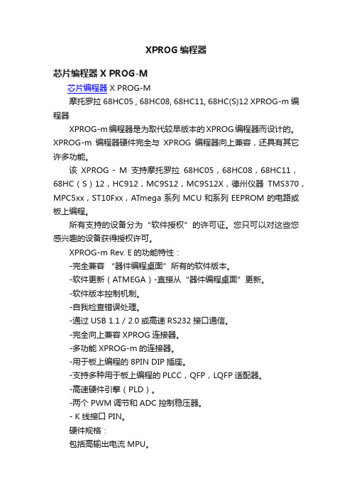
XPROG编程器芯片编程器 X PROG-M芯片编程器 X PROG-M摩托罗拉68HC05 , 68HC08, 68HC11, 68HC(S)12 XPROG-m编程器XPROG-m编程器是为取代较早版本的XPROG编程器而设计的。
XPROG-m编程器硬件完全与XPROG编程器向上兼容,还具有其它许多功能。
该XPROG - M支持摩托罗拉68HC05,68HC08,68HC11,68HC(S)12,HC912,MC9S12,MC9S12X,德州仪器TMS370,MPC5xx,ST10Fxx,ATmega系列MCU和系列EEPROM的电路或板上编程。
所有支持的设备分为“软件授权”的许可证。
您只可以对这些您感兴趣的设备获得授权许可。
XPROG-m Rev. E的功能特性:-完全兼容“器件编程桌面”所有的软件版本。
-软件更新(ATMEGA)-直接从“器件编程桌面”更新。
-软件版本控制机制。
-自我检查错误处理。
-通过USB 1.1 / 2.0或高速RS232接口通信。
-完全向上兼容XPROG连接器。
-多功能XPROG-m的连接器。
-用于板上编程的8PIN DIP插座。
-支持多种用于板上编程的PLCC,QFP,LQFP适配器。
-高速硬件引擎(PLD)。
-两个PWM调节和ADC控制稳压器。
- K线接口PIN。
硬件规格:包括高输出电流MPU。
板上设备编程的外部输出。
串行接口(最多115K波特率)用于(COM1,COM2,COM3或COM4)。
USB 1.1 / 2.0。
电力要求:功率消耗:三百毫安。
注意:如果编程器通过RS - 232串行端口连到电脑,则需要一个外置的12V直流电源。
如果编程器通过USB端口连到电脑,那么外部电源通常并不需要,但前提是必须确定USB接口可以提供足够的电力。
电脑的系统要求:-处理器:Intel Pentium 60MHz或更快(取决于操作系统)-内存(RAM):32MB(取决于操作系统)-硬盘:5MB的自由空间-通讯:一个COM端口或USB 1.1 / 2.0-操作系统:Microsoft Windows 95 / 98 /NT/ME/ 2000 / XP注意:USB接口不支持Windows NT 4.0或早期版本的Windows 98针对目前很多朋友,用正版XPROG读写CAS4-5M48H读丢或损坏CPU,本人在此将实战经验和大家分享,大家可参考,不一定正确。
SmartPRO系列编程器说明书

量产:不用重复点击此按钮,只需取放芯片即可。
11 制作脱机工程
点击软件界面中的“
”, 在弹出来的界面
中,填写脱机工程的相关信息。工程名称必填,其他均可选。存储介
质可以在“内置电子盘”与“CF卡”之间选择。点击“下载”按
钮,软件会自动将工程文件下载到编程器存储介质中。
12 载入脱机工程
在断开USB线的情况下打开编程器电源即可进入脱机模式。开机后按任意键进入菜单,进入“装载工程” 选项,选择存储介质以及指定的工程文件,并导入。
”,在弹出界面中,“类
型”选择为“All“之后,在“器件名称”处输入所需烧写的芯片型
号。在“器件”处选择确定型号后点击“选择”。
5 装载数据
点击软件界面中的“
”;在弹出对话框中,在
“查找范围”处找到需要烧写文件的路径并选择正确的文件。再点击
Байду номын сангаас
“打开”(如果没有所需要的格式,请在“文件类型”处选择“all
产品光盘
编程器软件光盘
PC-104转接口、RJ45-ICP2扁 ICP烧写专用线 网线、400mm扁平线
CF 卡
仅SmartPRO T9000-PLUS标配CF卡,用于脱机CF卡烧写。其余编程器型号选配
快速入门
1 安装软件
从配套光盘或 /downloads.asp 获取安装软件。双击图标 序,按提示进行完成安装。
广州致远电子股份有限公司始终致力于为电力、工业自动化和物联网领域提供高端测量分 析仪器、ARM/x86工控机、工业现场总线、人机界面和RFID无线通讯等超过500种产品,并 参与iCAN协议、数字示波器和逻辑分析仪等领域的多项国家标准制定工作,发展和提供高品 质、高性能的产品及服务。自2001年创立以来,经过10多年的发展,致远在工业自动化市场 积累了丰富的经验,并引领行业发展方向,为国内用户提供全套硬件、软件、客户服务和后台 支持等系统解决方案。致远将坚持不懈的协助系统集成商实现自身解决方案和服务的增值。
罗克韦尔 Compact 5000 I O 数字量模块 说明书

基于 EtherNet/IP 的连接 . . . . . . . . . . . . . . . . . . . . . . . . . . . . . . . . . . . 56 使用 External Means 时连接的其他注意事项 . . . . . . . . . . . . . . . . 57 受限操作 . . . . . . . . . . . . . . . . . . . . . . . . . . . . . . . . . . . . . . . . . . . . . . . . . . . . . . . 58 安全模块特定注意事项 . . . . . . . . . . . . . . . . . . . . . . . . . . . . . . . . . . . . . . . . 59 整体系统安全功能 . . . . . . . . . . . . . . . . . . . . . . . . . . . . . . . . . . . . . . . . . 60 单通道或双通道模式 . . . . . . . . . . . . . . . . . . . . . . . . . . . . . . . . . . . . . . . 60 与安全控制器结合使用 . . . . . . . . . . . . . . . . . . . . . . . . . . . . . . . . . . . . 61 确定符合性 . . . . . . . . . . . . . . . . . . . . . . . . . . . . . . . . . . . . . . . . . . . . . . . . 61
max硬件手册

xProGPS_max操作手册IAE公司2019年3月主要特点xProGPS_max 是一个非常灵活和强大的GPS 速度传感器也是一套数据采集系统,可提供100Hz 的GPS信号。
高速速度信息刷新率几乎是所有试验中最重要的输入。
高速且比传统GPS更精准的数据使得xProGPS_max 成为汽车测试中最优选择。
100 Hz 接收器可用来测试高动态速度变化,比如在制动测试中,或在原地起步加速测试中。
可以在软件中进行高动态测试的设置与参数调整。
xProGPS_max 除了主接收器外,还附带有一个辅助的高灵敏度的10 Hz GPS,可在主接收器无信号时继续工作。
标准模式下,车辆当前位置精度优于2.5 米CEP,如有必要,可通过附加设备提高精度。
GPS高度偏差通常在10 米左右。
为了获取更好的高度精度,xProGPS_max 内置了气压传感器,可将高度精度推进到大约2米左右。
xProGPS_max 有4个CAN 总线接口,1 个USB接口和1个标准的COM 接口。
通过COM接口将驾驶员显示器连接到xProGPS_max 时,它会变成一个完全独立的数据采集系统,可告诉记录数据到内置的SD卡上。
3个用户可用的CAN总线接口读取数据速度可达1 M/s,典型应用包括与车载CAN总线连接,以及扩展单元连接,扩展单元包括xProINS和32通道的热电偶模块xProTherm32 。
第4个CAN 总线接口用于内部通讯xProGPS_max有2 个计数器输入,这样传统的增量型编码器可以连接到设备用来测试车速或油耗。
通过这种方式,系统能提供测试车轮打滑或GPS失效的环境时车速信息的方法。
除了数字通道通讯,xProGPS_max 还通过2个模拟通道向外发送数据。
还有一个可编程频率同步器,可将输入通道转成频率,可以是3.3V TTL信号或开集输出。
测试可由特殊触发输入信号触发开始。
用户可选择使用被动接触,如制动踏板开关,或主动传感器如光栅等。
Emax EMAX2204 Brushless Outrunner Motor说明书
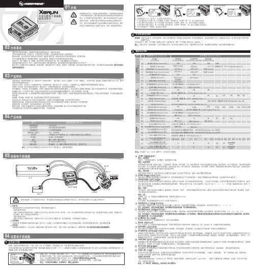
感谢您购买本产品!无刷动力系统功率强大,错误的使用可能造成人身伤害和设备损坏。
我们强烈建议您在使用设备前仔细阅读本说明书,并严格遵守规定的操作程序。
我们不承担因使用本产品而引起的任何责任,包括但不限于对附带损失或间接损失的赔偿责任;同时,我们不承担因擅自对产品进行修改所引起的任何责任。
我们有权在不经通知的情况下变更产品设计、外观、性能及使用要求。
· 电调与相关连接部件连接前,请确保所有电线和连接部件绝缘良好,短路会毁坏电调。
· 请务必仔细连接好各部件,若连接不良,您可能不能正常控制赛车,或出现设备损坏等其他不可预知的情况。
· 使用此电调前,请认真查看各动力设备以及车架说明书,确保动力搭配合理,避免因错误的动力搭配导致电机超载,最终损坏电调。
· 顶级竞赛专用:内置5种常用模式(如:零进角Zero Timing闪灯模式、一般练习模式、MODIFY 竞赛模式、STOCK 竞赛模式),适合所有竞赛,即选即用。
电调的设定参数可以导入导出,便于车 手相互交流和借鉴彼此的设定。
· 高度仅为15.9mm,比老款V3.1-1S电调约低6mm,车架布局更方便;重量只有35.6g,比老款V3.1-1S电调约轻12g,低重量为车架的平衡提供更多的可调空间。
03产品特色02注意事项电调第一次使用或遥控器更改过油门“TRIM”微调、D/R、EPA等参数后,均需重设油门行程,不然可能会导致无法使用或误动作。
06设置电子调速器设定油门行程1XERUN XR10 Pro 1S车用无刷电子调速器使用说明书01声明1. 连接马达:连接有感无刷马达与无感无刷马达的方式有差异,请务必遵照如下接线方式: · 连接有感无刷马达时:电调与马达相连有严格的线序要求,电调的#A/#B/#C必须与电机的#A/#B/#C三线严格一一对应,用6针感应线把电调与电机的感应口对接。
若有感无刷马达未接上感应线,则电调会工作 在无感模式,相当于电调连接无感无刷电机。
FLEX 5000高速计数器I O模块安装指南说明书

安裝說明FLEX 5000 高速計數器 I/O 模組型號 5094-HSC 、5094-HSCXT產品綜述5094-HSC 與 5094-HSCXT 高速計數器模組會計算從脈衝產生器、計數器、限制開關和其他裝置傳入的脈衝。
模組會將計數回傳到控制器,或啟動輸出來執行特定動作。
六個差動輸入包含計數器。
FLEX 5000™ I/O 模組使用生產者-消費者通訊模型。
生產者-消費者通訊模型是模組與其他系統裝置之間的⼀種智慧型資料交換,其中的每⼀個模組都不用先被輪詢即產生資料。
FLEX 5000 I/O 系列搭配使用⼀些 Logix 5000™ 控制器,並配置 Studio 5000 Logix Designer® 應用程式。
關於 Logix 5000 控制器與 Logix Designer 應用程式版本如何相容於 FLEX 5000 I/O 模組的更多資訊,請參閱第15 頁的其他資源所列的出版物。
主題 頁次關於模組5準備工作5必備元件5安裝模組7為端子基座配線8切斷端子基座的配線9配線圖10為 I/O 模組供電13移除模組14更換模組14模組規格14其他資源15FLEX 5000 高速計數器 I/O 模組2洛克威爾自動化出版物 5094-IN009A-ZC-P – 2018年5 月ATTENTION:Read this document and the documents listed in the Additional Resources section about installation, configuration and operation of this equipment before you install, configure, operate or maintain this product. Users are required to familiarize themselves with installation and wiring instructions in addition to requirements of all applicable codes, laws, and standards.Activities including installation, adjustments, putting into service, use, assembly, disassembly, and maintenance are required to be carried out by suitably trained personnel in accordance with applicable code of practice.If this equipment is used in a manner not specified by the manufacturer, the protection provided by the equipment may be impaired.注意:在安装、配置、操作和维护本产品前,请阅读本文档以及“其他资源”部分列出的有关设备安装、配置和操作的相应文档。
GP-Pro EX 控制器 PLC 连接手册说明书
PROFIBUS InternationalPROFIBUS DP Slave驱动程序1系统配置 (3)2选择外接控制器 (6)3通讯设置示例 (7)4设置项目 (11)5支持的寄存器 (15)6寄存器和地址代码 (16)7错误消息 (17)简介本手册介绍如何连接人机界面和外接控制器(目标PLC)。
在本手册中,将按以下章节顺序介绍连接步骤:1系统配置)“1 系统配置” (第3页)本节介绍可连接的外接控制器和串口的类型。
2选择外接控制器)“2 选择外接控制器” (第6页)选择要连接的外接控制器的机型(系列)以及连接方法。
3通讯设置示例)“3 通讯设置示例” (第7页)本节给出连接人机界面和外接控制器的设置示例。
4设置项目)“4 设置项目” (第11页)本节介绍人机界面上的通讯设置项目。
请使用GP-Pro EX或在离线模式下进行人机界面的通讯设置。
操作1系统配置给出PROFIBUS DP 主站的外接控制器和人机界面连接时的系统配置。
连接配置PROFIBUS DP 主站的I/O 内存容量大小决定了可连接到PROFIBUS DP 主站的人机界面的最大数量。
例如,如果PROFIBUS DP 主站的I/O 内存容量为64个字,假设每个PROFIBUS 从站使用16个字 (输入区域和输出区域的总和),则最多可连接的人机界面的数量就是4台。
有关内存容量的更多详情,请参阅各制造商的外接控制器手册。
系列CPU通讯接口设置示例串口类型Siemens SIMATC S7-300/400系列带有DP 端口的所有CPU外接控制器上的PROFIBUS DP 接口设置示例1 (第7页)PROFIBUS设置示例2 (第9页)*1*1使用包传输时的设置示例。
支持PROFIBUS DP 主站的其他公司的控制器PROFIBUS DP 接口设置示例1 (第7页)PROFIBUS DP Master 之间的电缆接线图的更多信息,以及有关PROFIBUS 模块的更多信息请参阅“GP3000系列PROFIBUS 模块用户手册”。
汽车数码大师III说明书

重要说明 此说明书仅提供用户参考,南宁研华电子科技有限公司保留不发出通知就改变其产品或
产品说明书的权利,保留不更新本文档以反映这些改变的权利。
南宁研华电子科技有限公司
科技创新 超值服务
一 产品简介
1 功能特点 本仪器适用于汽车音响解码、读取防盗密码、气囊电脑修复、里程表调校、发动机 ECU
编程和数据编程等。 (1)所有操作改为网页式向导提示,一步一步告诉您如何操作。能看书能操作,支持车
② 对于可读写密码的音响,单击按钮“本地操作”以后软件会提示要保存码片的原始 数据,(“保存”自动保存到默认路径:C:\Program Files\数码大师3\用户数据目录\中)软 件会自动读取该型号音响的密码,码片装回音响后用该密码开机。
(5)修改数据 获取密码后即可用密码解开音响,如不需要修改码片内部数据,音响解码操作完成,可
电话取得联系方可操作) (6)硬件程序、软件程序全部均可网上升级。 (7)授权方式: 终身授权:是一种一次性买断现有车型的授权方式; 续费使用授权:是一种扣除点数的使用方式,当设备中原有点数扣除尽时,用户可 灵活购买使用所需点数进行充值。
2 数码大师Ⅲ仪器
-1-
南宁研华电子科技有限公司
二 软件安装
-6-
南宁研华电子科技有限公司
科技创新 超值服务
六 示例
1 专用编程器 专用编程器是特别针对汽车上使用的一些存储器(俗称码片,是存储汽车
常用数据、密码的器件)对其数据进行读出、显示、保存及改写的专用工具。 主要适用汽车仪表、发动机电脑、气囊电脑常用数据的调校及故障分析处理、 电 脑 程 序 匹 配 、音 响 解 码 、安 全 气 囊 (SRS)灯 。它 不 同 于 各 种 汽 车 原 厂 专 用 工 具 , 它们只适用于特定车型,而专用编程器无论是什么厂的车,什么型号的车,只 要找到这个存储数据的地方,我们就可以解决上述问题。如果再配以相应功能 模 块 ( 音 响 解 码 模 块 、 里 程 表 调 校 模 块 、 防 盗 读 码 器 模 块 、) 则 可 快 速 、 准 确 解 决修车中遇到的技术难题。使用说明如下: