Fristam泵中文操作手册
Fristam泵中文操作手册

1. 拆卸
4
1.1 总则
4
1.2 叶轮
4
1.3 完全拆卸
4
2. 装配
4
2.1 总则
4
2.1.1 设定间隙
4
2.1.2 螺钉紧固扭矩
5
2.2 FPE 的装配
5
2.3 FPE 带双轴封
5
3
AASSSSEEMMBBLLYY IINNSSTTRRUUCCTTIIOONNSS FFPZE
1. 拆卸 1.1 总则
2.2 泵的装配
1. 从电机轴上取下滑键.
2. 擦净电机轴上的油脂,套上泵的 套轴.
3. 把滑键嵌入电机轴(仅适用电机 > 30 kW).
4. 在电机轴肩处涂一圈密封胶(例 如Stucarit 309).
5. 把带胀紧套的套轴推至电机轴 轴肩处.
6. 旋紧胀紧套上的内六角螺钉至 十字位置(见表4).
11. 安装轴封的前端密封,剪断尼龙 环,嵌入轴螺纹后端的凹槽中.
12. 在叶轮螺母中嵌入O型圈,把叶 轮推入泵轴,在确保不翘曲时旋 紧叶轮螺母,紧定扭矩为100Nm.
13. 通过调整泵壳进入卡盘的距离 来设置泵盖/叶轮/泵体间的间隙, ( 仅 适 用 于 711/2 , 721/2 , 741/2) 通 过 在 泵 壳 和 法 兰 装 上 薄垫片来调整间隙(仅适用于 1051/2, 1151/2, 1231/2, 1251/2, 101/102-200, 101/102250) (参见表1).
M5
M6
Nm
6
12
表4: 胀紧套上的锁紧螺钉紧定扭矩
7. 检查套轴的同心度和直线度,同 心度依据下表:
电机功率 ≤ 30 kW > 30 kW
水泵使用说明中英文

水泵安装、使用、维护说明书Type NG slurry PumpINST ALL TION, OPERA TION, MAINTENANCEMANUAL一、水泵的安装Pump installation水泵的安装Pump installation1、水泵安装准备工作1. The preparation work for pump installation.(1)检查水泵和电机,确知在运输和装卸过程中没有损伤。
Check the pump and motor, ensure there were no damage during the transportation and load or unload.(2)检查工具和起重机械,并检查机器的基础。
Check the tools and lifting equipment and also the basement of machine. (3)检查配套提供的压力表及表座。
Check the manometer and gauge stand of affiliated equipments2、水泵安装顺序Pump installation order(1)整套泵运抵现场时,都已装好电机;校平底座时,可不必卸下水泵和电机。
The motor have been installed when a whole set of pump arrived scene. When collate the basement, no need to demount the pump and motor.(2)在水泥基础上安装水泵时,基础平面应用水平找平,待基础水泥凝固后将泵安装在基础上,并用水平仪检查水平情况,如不平,应用垫铁调正,直到水平为止,然后通过灌浆孔由混凝土浇灌底座和地脚螺栓孔眼。
When install pump on the cement base, regulate the foundation flat by the standard. Check the condition of standard by thegradienter, if not flat, regulate it by the parallels until horizontal, use concrete to irrigate basement and foundation bolt hole by the grout hole. (3)水泥干固后,检查底座和地脚螺栓是否松动,合适后拧紧地脚螺栓的螺母,最后再检查一下整台机组的水平度,稍有不平时,可用斜铁找平。
玛尔斯泵工安全操作规程模版(2篇)

玛尔斯泵工安全操作规程模版工安操作规程模版第一章总则第一条根据《特种设备安全法》、《特种设备安全法实施细则》、《特种设备使用单位安全管理规定》等国家法律法规的规定,结合我公司特种设备使用实际,制定本工安操作规程。
第二条本规程适用于我公司特种设备(包括玛尔斯泵等)的安全管理和操作使用人员。
特种设备操作人员应严格遵守本规程。
第三条特种设备操作管理人员应按照国家法律法规和公司制度规定履职尽责,确保特种设备安全运行。
第四条特种设备操作人员应通过专业培训和资格考核,持有相关特种设备操作证书方可上岗操作。
第五条特种设备操作人员应熟悉特种设备的结构、工作原理和使用方法,严格按照操作规程操作,保证设备安全运行。
第六条特种设备操作人员在操作过程中应注意保持良好的工作状态,不得酗酒、吸烟或服用影响操作安全的药物。
第七条特种设备操作人员应自觉遵守操作纪律,不得擅自修改设备工作参数或进行未经许可的操作。
第八条特种设备操作人员应与配合其他工作人员进行有效的沟通,协作完成各项任务。
第九条特种设备操作人员应熟悉特种设备的应急救援措施,遇到突发情况时应立即采取相应的措施并报告有关部门。
第十条特种设备操作人员应逐年接受安全培训和考核,提高安全意识和操作技能。
第二章特种设备安全管理第十一条玛尔斯泵设备应配备设备管理人员,负责设备的日常维护、检查和故障排除,保证设备的正常运行。
第十二条玛尔斯泵设备在运行前应进行设备检查,确定设备各项指标是否正常,确保设备运行安全。
第十三条玛尔斯泵设备的使用人员应严格按照设备操作手册中的操作规程进行操作,不得擅自更改工作参数或进行未经许可的操作。
第十四条玛尔斯泵设备操作人员应熟悉设备的工作原理和操作方法,能够独立操作设备,并且具备一定的维修技能。
第十五条玛尔斯泵设备操作人员应定期进行设备维修保养工作,保持设备的正常运行。
第十六条玛尔斯泵设备的检修和维护应由经过培训合格的人员进行,确保设备的安全可靠。
第十七条玛尔斯泵设备的维修记录应详细完整,记录设备的检修情况,及时消除设备故障隐患。
玛尔斯泵安全操作规程范本(三篇)

玛尔斯泵安全操作规程范本1. 前言本安全操作规程旨在保障使用玛尔斯泵的人员的安全,在操作过程中避免事故和伤害的发生。
所有使用玛尔斯泵的人员都必须严格遵守本规程的要求并参与相应的培训。
2. 泵房准备2.1. 操作人员在进入泵房之前,必须佩戴防护设备,包括耐酸碱手套、防冲击眼镜、防滑鞋等。
2.2. 在操作前,操作人员应确保泵房内通风良好,并检查泵房是否有明火或易燃物品,必要时进行清理。
2.3. 操作人员应检查泵房中的电源和电气设备是否正常运作,确保其无损坏和漏电的情况。
3. 泵的安装和连接3.1. 在安装玛尔斯泵之前,操作人员应仔细阅读产品说明书,并确保泵的安装位置稳定并符合要求。
3.2. 操作人员应使用合适的工具和设备,正确安装玛尔斯泵的进出口连接。
连接过程中要确保连接紧固并无漏水现象。
3.3. 在连接电源之前,操作人员必须确保泵的电气接线正确、牢固。
4. 泵的开启和运行4.1. 操作人员在启动玛尔斯泵之前,应确保泵房内其他设备处于正常关闭状态,并且工作区域无人。
4.2. 启动泵之前,操作人员应检查泵的旋转部件是否润滑良好,并确保无异常声音或振动。
4.3. 操作人员在启动泵时应以低档速度进行试运行,确保泵的运行平稳无异常。
5. 泵的停止和维护5.1. 停止泵运行前,操作人员必须先关闭电源,并确保泵的电源断开,防止意外启动。
5.2. 维护人员在进行玛尔斯泵的维护和保养时,必须戴好防护手套和眼镜,防止化学物品对皮肤和眼睛的损害。
5.3. 维护人员在更换泵的零件时,应使用原厂配件,并按照产品说明进行正确的安装和调试。
6. 应急处理6.1. 在紧急情况下,如发生火灾、漏水等,操作人员必须立即关闭玛尔斯泵的电源,并报告相关负责人。
6.2. 在泵房发生泵的故障时,操作人员应及时通知维修人员,并按照其指示进行应急处理,严禁擅自进行维修。
7. 泵的检查和记录7.1. 泵的定期检查和巡视是确保其安全运行的重要环节,操作人员应遵守规定的检查周期和方式。
玛尔斯泵安全操作规程(2篇)
玛尔斯泵安全操作规程第一章总则第一条为了保证玛尔斯泵的使用安全,保护操作人员的人身安全和设备的完好性,制定本安全操作规程。
第二条本规程适用于所有使用玛尔斯泵的操作人员。
第三条操作人员必须遵守本规程的规定,严格按照操作流程进行操作,确保泵的安全运行。
第四条管理部门应当定期对操作人员进行安全培训和技术培训,提高操作人员的安全意识和专业技能。
第五条操作人员应当仔细阅读并遵守使用手册中的安全操作规程和注意事项。
第二章安全操作规程第六条操作人员在操作玛尔斯泵前,必须穿戴好安全防护设备,包括防护眼镜、手套、耳塞等。
第七条操作人员在操作玛尔斯泵前,必须熟悉泵的组成结构、工作原理和性能参数,了解各部件的功能和作用。
第八条操作人员在操作玛尔斯泵前,必须检查泵的工作状态,确保泵的运行正常,无任何故障。
第九条操作人员在操作玛尔斯泵过程中,禁止使用过大的力气,防止损坏泵的零部件。
第十条操作人员在操作玛尔斯泵过程中,禁止任意调整泵的工作参数,保持泵的工作稳定。
第十一条操作人员在操作玛尔斯泵过程中,必须定期检查泵的润滑系统和冷却系统,确保其正常运行。
第十二条操作人员在操作玛尔斯泵过程中,禁止将异物投入泵中,防止堵塞泵的管道。
第十三条操作人员在操作玛尔斯泵过程中,禁止随意拆卸泵的零部件,必须由专业人员进行维修和保养。
第十四条操作人员在操作玛尔斯泵过程中,禁止将泵用于非正常用途,防止设备损坏和事故发生。
第十五条操作人员在操作玛尔斯泵过程中,发现任何异常情况,应立即停止操作,并向管理部门报告。
第十六条操作人员在操作玛尔斯泵过程中,应遵守现场安全规定,确保现场整洁,防止意外伤害发生。
第三章应急处置措施第十七条操作人员在操作玛尔斯泵过程中,发生泵的故障或事故时,应立即按照应急预案进行处置。
第十八条操作人员在操作玛尔斯泵过程中,发生火灾、爆炸等紧急情况时,应立即切断电源,并按照应急预案进行处置。
第十九条操作人员在操作玛尔斯泵过程中,发生人身伤害时,应立即停止操作,进行急救,并及时报告管理部门。
水泵操作手册说明书

operation manual23table of contentsIntroduction 4 Using the Operators ManualProduct Identification 5 Water Pump5 EngineSafety 6 Safety Rules6 Hazard Symbols and MeaningsWater Pump Components 11 Component ChartAssembly 12 Connect Suction Hose to Pump12 Attach Suction Hose to Strainer Basket12 Connect Discharge HoseOperation 14 What is “Head”14 Move Water Pump to Safe Location15 Prime the Water Pump16 Locate Strainer Basket Into Water SourceStarting The Water Pump 17 Starting the Water PumpStopping The Water Pump 19 Stopping the Water Pump19 Drain and Flush Water Pump4Using the Operator’s manual The operating manual is an important part of your water pump and should be read thoroughly before initial use, and referred to often to make sure adequate safety and service concerns are being addressed.Reading the owner’s manual thoroughly will help avoid any personal injury or damage to your machine. By knowing how best to operate this machine you will be better positioned to show others who may also operate the unit.This manual contains information for the complete range of BE water pumps, and is placed in order starting from the safety requirements to the operating functions of your machine. You can refer back to the manual at any time to help troubleshoot any specific operating functions, so store it with the machine at all times.Attention: Read through the complete manual prior to the initial use of your water pumpintroduction5product identificationRecord Identification NumbersWater Pump If you need to contact an Authorized Dealer or Customer Service line (1-866-850-6662) for information on servicing, always provide the product model and identification numbers.You will need to locate the model and serial number for the machine and record the information in the places provided below. Date of Purchase:Dealer Name:Dealer Phone:Product Identification NumbersModel Number:Serial Number:EngineHorse Power:6you to hazards. DANGER indicates a hazard which, if not avoided, will result in death or serious injury. WARNING indicates a hazard which, if not avoided, could result in death or serious injury. CAUTION indicates a hazard which, if not avoided, might result in minor or moderate injury. NOTICE indicates a situation that could result in equipment damage.Follow safety messages to avoid or reduce the risk of injury or death.Hazard Symbols and MeaningsSave these InstructionsSafety Rules safetyThis is the safety alert symbol. It is used to alert you to potential personal injury hazards. Obey all safety messages that follow this symbol toavoid possible injury or death.7safety Running engine gives off carbon monoxide, an odorless, 8safety9safety Starter cord kickback (rapid retraction) can result in• NEVER place hands or body parts inside of running pump or hoses.10safety Excessively high operating speeds increase risk of injury and damage 11Read this operator’s manual and safety rules before operating your water pump.water pump components1. Fuel Tank Fill tank with regular unleaded fuel. Always leave room for fuel expansion.2. Priming Plug Fill pump with water here to prime pump before starting.3. Discharge Outlet Connect discharge hose here.4. Choke Lever Prepares a cold engine for starting.5. Air Cleaner Protects engine by filtering dust and debris out of intake air.6. Recoil Starter Used for starting the engine manually.7. Engine Speed Lever Used to adjust engine speed to control pump output.8. On/Off Switch Set this switch to “On” before using recoil starter. Set switch to “Off” to stop a running engine.9. Oil Drain Drain engine oil here.10. Oil Fill Check and add engine oil here.11. Suction Inlet Connect reinforced suction hose here.12. Water Drain Plug Remove to drain water from pump and flush internal components with clean water.13. Pump Chamber Be sure to fill with water before starting.14. Fuel Shutoff Valve Used to turn fuel supply on and off to engine.Item Not Shown:Strainer Basket Used to limit passage of abrasive materials into the pump.1.4.6.8.9.10.11.12.13.14.7.5.2. 3.assemblyYour water pump requires some set up and is ready for use after it has been properly serviced with the recommended oil and fuel.ewdriver.hose with an inside diameter smaller than the pump’s discharge port size.1.Slide barb cuff over hose barb. Insert rubber seal into end of barb cuff as shown earler.2.Screw hose barb assembly onto pump in clockwise rotation until hose barb assembly is tightened securely.assembly discharge port size.1.Slide barb cuff over hose barb. Insert rubber seal into 2.Screw hose barb assembly onto pump in clockwise rotation until hose barb assembly is tightened securely.14What is “Head”Head refers to the height of a column of water that can be delivered by the discharge of the pump.Suction Head is the vertical distance between the center of the pump and the surface of the liquid on the suction side of the pump. May also be referred to as “suction lift”. The atmospheric pressure of 14.7 psi at sea level limits suction head lift to less than approximately 26 feet for any pump.Discharge Head is the vertical distance between the pump’s discharge port and the point of discharge, which is the liquid surface if the hose is submerged or pumping into the bottom of a tank.Total Head is the sum of the suction head value plus the discharge head value.As water pumping height increases, pump output decreases. The length, type, and size of the suction and discharge hoses can also significantly affect pump output. It is important for the suction operation to be the shorter part of the total pumping action. This will decrease the priming time and improve pump performance by increasing the discharge head.Suction head is a maximum of 25 feet and discharge head should be a maximum of 81 feet. Total head can not be more than 106 feet as shown on next page.Move Water Pump to Safe Operating Location For best pump performance, locate the pump on a flat, level surface as close as possible to the water to be pumped. Secure water pump to avoid tipover. Use hoses that are no longer than necessary.IMPORTANT: Direct open end of discharge hose away from home, electrical devices or anything not desired to get wet.operation15Prime the Water Pump 1. Remove priming plug from top of pump.2. Fill pump with clean, clear water up to top of discharge outlet.3. Replace priming plug.operation16Locate Strainer Basket Into Water Source Place strainer basket into water to be pumped. Basket must be fully immersed.operation17Starting the Water Pump Use the following start instructions:1. Make sure unit is on a flat, level surface and pump chamber is primed.2. Turn fuel valve (1) to “On” position. The fuel valve handle will be starting the water pump18IMPORTANT: If excessive fuel is present in the air/fuel mixture causing a “flooded” condition, move choke lever to “Run” position and pull handle repeatedly until engine starts.7. Move choke lever to “Run” position a short distance at a time over several seconds in warm weather or minutes in cold weather. Let engine run smoothly before each change. Operate with choke in “Run” position.IMPORTANT: It may take a few minutes for water pump to begin pumping water.Pump output is controlled by adjusting engine speed. Moving the engine speed lever in the “Fast” direction will increase pump output, and moving the engine speed lever in the “Slow” direction will decrease pump output.starting the water pump19stopping the water pumpStopping the Water Pump 1. Move engine speed lever to “Slow” position.2. Push on/off switch to “Off” position.3. Turn fuel valve to “Off” position.Drain and Flush Water Pump 1. Disconnect and drain suction and discharge hoses.2. Remove drain plug at bottom of pump.3. Remove primer plug from top of pump and flush internal components of pump with clean water.If you need assistance with the assembly or operation of this Water Pump please call 1-866-850-6662。
微量泵竖泵的操作流程及注意事项

微量泵竖泵的操作流程及注意事项1.打开微量泵的电源开关。
Turn on the power switch of the micro pump.2.确保微量泵处于停止状态。
Make sure the micro pump is in the stopped state.3.察看微量泵的液体储存容器是否已安装并装满液体。
Check if the liquid storage container of the micro pump is installed and filled with liquid.4.按下启动按钮,启动微量泵。
Press the start button to start the micro pump.5.调节微量泵的流量大小和速度。
Adjust the flow rate and speed of the micro pump.6.监视微量泵的运行状态,确保其正常工作。
Monitor the operation of the micro pump to ensure it is working properly.7.当需要停止时,按下停止按钮。
Press the stop button when it is necessary to stop.8.关闭微量泵的电源开关。
Turn off the power switch of the micro pump.9.保持微量泵的清洁,定期清洗泵头和管路。
Keep the micro pump clean and clean the pump head and pipes regularly.10.注意不要让微量泵运行过载,避免损坏设备。
Be careful not to overload the micro pump to avoid damaging the equipment.11.定期检查微量泵的零部件,及时更换损坏的部分。
Regularly check the components of the micro pump and replace damaged parts in time.12.在操作微量泵时,注意安全防护,避免触电或者溢液事故。
福尼亚胰岛素泵操作讲解.pptx
设置3(时钟)
从初始画面 ACT 主画面 ACT 设置 SEL 时钟 ACT 时钟页面
时钟设置: 按SEL键下标将
在年、月、日、 时、分钟之间进 行切换。
下标对应选项 通过▲ 或 键 调节,要与当前 时间调节一致。
设置完毕后按 “ACT”键进行保 存,保存后将回 到初始画面。
设置3(时钟)
设置年、月、日及小时、分钟时,修改其中任一 值,按“ACT”键退出并保存修改值,修改了某一值但 未按“ACT”键自动退出,将保留原始时间值。时间设 定具有闰年日期自动调整功能。电池取出后,胰岛素 泵的记时功能仍在进行
第 【1】 次 餐前大剂量 请遵医嘱
SEL A CT
ACT键确认,进入提示 画面。
餐前—A0、B0模式
ACT键选择。
ACT键开始输注。
注:24小时允许8次餐前大 剂量输注。
餐前—A0、B0模式
ACT键选择。
ACT键开始输注。
注:24小时允许8次餐前大 剂量输注。
餐前
餐前量的给药操作需要使用者自己操作。 短效胰岛素使用者,选择使用A0、A1模式,使用者必须在 餐前量注射结束30分钟后进食,泵将在注射结束30分钟后发出 提示音乐。按任意键可以终止该音乐提示。 超短效胰岛素使用者,选择B0、B1模式,使用者在注射结 束后需立即进食。 在输注过程中,如果需要停止餐前大剂量胰岛素的输注, 可以按任意键手动停止输注,再按“ACT”键停止输注并返回 初始画面。 无论是哪种模式进行大剂量输注,当没有真正输注而自动 退出时,此次操作视为无效操作,不被记录次数,但当进行输 注操作而输注中途取消输注则视为有效操作,此次操作被作为 一次被记录次数。
主画面
从初始画面按“ACT”键进入“主画面”,如下图。
泵类操作说明

泵类操作说明离心泵和自吸泵1、使用与保养(1)新泵使用前,应先拨动电机后面风叶或(联轴器),检查转动是否均匀、灵活、无异声。
(2)新泵首次使用,应先点动检查电机转向,正确的转向为从电机风叶看为顺时针旋转。
(3)开机前,应全部打开进口阀,使泵体及进口管路内充满液体。
(4)用出口调节阀调节泵的流量和扬程,使泵在设计的工况下运行,以获得最大节能效果,进口阀必须全部打开。
(5)在运行中应检查泵进出口压力是否符合泵的性能范围,电机功率有无超载,机封是否泄漏,电机的温升是否超标等。
2、注意事项(1)泵严禁缺液空转,必须充满液体后启动,以免损坏机封。
(2)泵严禁反转。
(3)泵严禁通过调节进口阀来调整使用性能参数,以免产生汽蚀而造成损坏。
(4)停机前,应先关闭出口调节阀,后断电源停机。
(5)如发现泵有殿堂声音、电机温长过高,电流过大等特殊情况,应立即停机检查。
齿轮泵1、泵工作时的维护(1)泵的压力及真空表的读数应符合该泵所规定的技术规范。
(2)当泵在动转中出现不正常的噪音或温升进高时,应立即停止泵的工作,进行拆检。
(3)一般情况下,不得调整安全阀,如需调整时,要用仪器校正。
2、泵工作的停止(1)切断电源;(2)关闭进出管道的阀门。
水环真空泵1、起动和停车起动:起动前,特别是长期停车的泵必须用手转动联轴器数转,确认转子能自由转动才行。
起动前应将泵体内的水全部放掉,方可起动。
起动顺序:a、关闭进气管路上的闸阀;b、打开供水管路上的闸阀,供水量逐渐增加,至供水量符合规定要求为止;c、开动电动机(此时应注意电机的正反转,在向泵体供水后应立即开动电机);d、当泵达到极限真空时,打开进气管路上的闸阀,泵开始正常工作;e、调整填料压盖,使水成滴往外滴为好,真空泵在极限真空下工作时,由于泵内产生物理作用而发生爆炸声,但功率消耗并不增大,如发现随着功率增加而产生的爆炸声,说明泵已发生故障,此时应立即停车检查。
停车:停车顺序:a、关闭进气管路上的闸阀;b、关闭供水管路上的闸阀,停水后,不应立即停泵,应使泵继续运转1-2分钟,排出部分工作液;c、关闭电动机。
弗里森泵业离心泵操作手册

身危害 z 由于危险物质泄漏而导致的环境
危害
2.4 自觉安全生产
操作手册中包含的安全说明,现有的 国家事故防范条例和用户自行发布的 任何内部工作,操作及安全规则都必 须遵守.
2.5 对于用户和操作者的安全 说明
2.7 未经授权的更改和备件加 工
要更改或改造机器,必须与制造商咨 询后才能进行.由制造商授权的原装 备件和附件能提高安全性.对于使用 其它厂家部件而导致的后果是不负责 任的.
2.8 不允许的操作方法
只有当正确使用时,机器的运转才能 确保安全.不允许超越此系列文件规 定的限定值.
吊车和吊绳须保证 有足够的承受力和强度.电机的吊钩 并不适合用来吊升或运输泵. 但 FP1250是例外,它装在泵壳,轴承座4, 电机上的吊钩可以用来运输.
化学品: 显影乳液,酸碱溶液, 包含晶体的废水,清洁液.
并且可以在以下生产过程中应用:
水处理 蒸发 蒸馏 脱醇 反渗透 过滤 萃取 炭化处理 加热/加压 发酵 乳化 均质 机械分馏 透析 罐装 定量给料 去气 传输 自清洗/CIP 在线混料
2. 安全
此操作手册中包含在安装,操作,保养 过程中,几个必须遵守的重要基本指 示.
减轻管线对泵的压力
气袋会导致危险 z 避免沉积
5.2 安装前的检查
泵在运转前必须清洗干净.而且须确 保没有杂质通过系统进入泵.
5.3 电力安装
5.4.2 吸入管路
z 尽可能短一些. z 在吸入端口前不允许弯曲管路.
如果泵没装备防爆电 机,则绝对不能在易爆的环境操作. 在安装过程中,要小心操作,确保泵没 有受外力的影响而变形. 避免泵的变形要做到:
浦发泵一号一半泵操作手册说明书
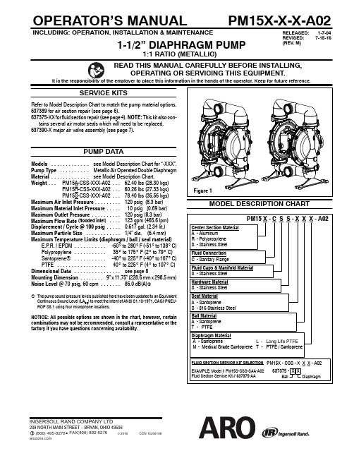
1-1/2”DIAPHRAGM PUMPOPERATOR’S MANUALPM15X-X-X-A02RELEASED:1-7-04REVISED:7-15-16(REV. M )INCLUDING:OPERATION,INSTALLATION &MAINTENANCESERVICE KITSRefer to Model Description Chart to match the pump material options.637389for air section repair (see page 6).637375-XX for fluid section repair (see page 4).NOTE:This kit also con-tains several air motor seals which will need to be replaced.637390-X major air valve assembly (see page 7).PUMP DATAModels see Model Description Chart for “-XXX”..............Pump Type Metallic Air Operated Double Diaphragm ..........Material see Model Description Chart..............Weight PM15A-CSS-XXX-A0262.40lbs (28.30kgs)......PM15R-CSS-XXX-A0260.26lbs (27.33kgs)...PM15S-CSS-XXX-A0278.40lbs (35.56kgs)...Maximum Air Inlet Pressure 120psig (8.3bar).........Maximum Material Inlet Pressure 10psig (0.69bar).....Maximum Outlet Pressure 120psig (8.3bar)..........Maximum Flow Rate (flooded inlet )123gpm (465.6lpm)....Displacement /Cycle @100psig 0.617gal.(2.34lit.).....Maximum Particle Size 1/4”dia.(6.4mm)............Maximum Temperature Limits (diaphragm /ball /seal material)E.P.R./EPDM -60_to 280_F (-51_to 138_C)...........Polypropylene 35_to 175_F (2_to 79_C)...........Santoprene R -40_to 225_F (-40_to 107_C)...........PTFE 40_to 225_F (4_to 107_C).................Dimensional Data see page 8................Mounting Dimension 9”x 11.75”(228.6mm x 298.5mm)........Noise Level @70psig,60cpm 85.0dB(A)....... The pump sound pressure levels published here have been updated to an Equivalent Continuous Sound Level (LA eq )to meet the intent of ANSI S1.13-1971,CAGI-PNEU-ROP S5.1using four microphone locations.NOTICE:All possible options are shown in the chart,however,certain combinations may not be recommended,consult a representative or the factory if you have questions concerning availability .Figure 1MODEL DESCRIPTION CHARTINGERSOLL RAND COMPANY LTD209 NORTH MAIN STREET – BRYAN, OHIO 43506(800) 495-0276 FAX(800) 892-6276© 2016CCN 15206188OPERATING AND SAFETY PRECAUTIONSREAD,UNDERSTAND,AND FOLLOW THIS INFORMATION TO AVOID INJURY AND PROPERTY DAMAGE.EXCESSIVE AIR PRESSURESTATIC SPARKHAZARDOUS MATERIALSHAZARDOUS PRESSUREWARNING EXCESSIVE AIR PRESSURE.Can cause person-al damage or property damage.S Do not exceed the maximum inlet air pressure as stated on thepump model plate.S Be sure material hoses and other components are able to with-stand fluid pressures developed by this pump.Check all hosesfor damage or wear.Be certain dispensing device is clean andin condition.WARNING STATIC SPARK.Can cause explosion resulting insevere or death.Ground pump and pumping system.S Sparks can ignite flammable material and vapors.S The pumping system and object being sprayed must begrounded when it is pumping,flushing,recirculating or spray-ing flammable materials such as paints,solvents,lacquers,etc.or used in a location where surrounding atmosphere isconducive to spontaneous combustion.Ground the dispens-ing valve or device,containers,hoses and any object to whichmaterial is being pumped.S Secure pump,connections and all contact points to avoidvibration and generation of contact or static spark.S Consult local building codes and electrical codes for specificgrounding requirements.S Aftergrounding,periodicallyverifycontinuityofelectricalpathto ground.Test with an ohmmeter from each component(e.g.,hoses,pump,clamps,container,spray gun,etc.)to ground toensure continuity.Ohmmeter should show0.1ohms or less.S Submerse the outlet hose end,dispensing valve or device inthe material being dispensed if possible.(Avoid free streamingof material being dispensed.)S Use hoses incorporating a static wire.S Use proper ventilation.S Keep inflammables away from heat,open flames and sparks.S Keep closed when not in use.WARNING Pump exhaust may contain contaminants.Cancausesevereinjury.Pipeexhaustawayfromworkareaandper-sonnel.S In the event of a diaphragm rupture,material can be forced outof the air exhaust muffler.S Pipe the exhaust to a safe remote location when pumping haz-ardous or inflammable materials.S Use a grounded3/4”minimum i.d.hose between the pump andtheWARNING HAZARDOUS PRESSURE.Can result in seriousinjury damage.Do not service or clean pump,hoses or dispensing valve while the system is pressurized.S Disconnect air supply line and relieve pressure from the sys-tem by opening dispensing valve or device and/or carefullyand slowly loosening and removing outlet hose or piping frompump.WARNING HAZARDOUSMATERIALS.Cancauseseriousin-jury damage.Do not attempt to return a pump to thefactory or service center that contains hazardous material.Safe handling practices must comply with local and nationallaws and safety code requirements.S Obtain Material Safety Data Sheets on all materials from thesupplier handling instructions.WARNING EXPLOSION HAZARD.Models containing alumi-num cannot be used with III.-Trichloroethane,Me-thylene Chloride or other Halogenated Hydrocarbon solventswhich may react and explode.S Check pump motor section,fluid caps,manifolds and allwetted partsto assurecompatibilitybeforeusing withsolventsofWARNING MISAPPLICATION HAZARD.Do not use modelscontaining wetted parts with food products for hu-man consumption.Plated parts can contain trace amounts oflead.CAUTION Verify the chemical compatibility of the pumpwetted the substance being pumped,flushed or re-circulated.Chemical compatibility may change with tempera-ture and concentration of the chemical(s)within thesubstances being pumped,flushed or circulated.For specificfluid consult the chemical manufacturer.CAUTION Maximum temperatures are based on mechani-cal Certain chemicals will significantly reducemaximum safe operating temperature.Consult the chemicalmanufacturer for chemical compatibility and temperature lim-its.DATA on page1of this manual.CAUTION Be certain all operators of this equipment havebeen safe working practices,understand it’s limita-tions,safety goggles/equipment when required.CAUTION Do not use the pump for the structural support ofthe Be certain the system components areproperly supported to prevent stress on the pump parts.S Suction and discharge connections should be flexible connec-tions(such as hose),not rigid piped,and should be compatiblewith being pumped.CAUTION Prevent unnecessary damage to the pump.Donot to operatewhen outof materialforlongperiodsof time.S Disconnect air line from pump when system sits idle for longperiodsCAUTION Use only genuine AROreplacement parts to as-sure pressure rating and longest service life.RE-TORQUE ALL FASTENERS BEFORE OPERA-housing and gasket materials may cause fas-tenersto loosen.Re-torqueallfastenersto ensure against fluidor air leakageWARNINGCAUTIONPM15X-X-X-A02 Page2of8GENERAL DESCRIPTIONThe ARO R diaphragm pump offers high volume delivery even at low air pressure and a broad range of material compatibility options available. Refer to the model and option chart.ARO pumps feature stall resistant design,modular air motor/fluid sections.Air operated double diaphragm pumps utilize a pressure differential in the air chambers to alternately create suction and positive fluid pressure in the fluid chambers,ball checks ensure a positive flow of fluid. Pump cycling will begin as air pressure is applied and it will continue to pump and keep up with the demand.It will build and maintain line pres-sure and will stop cycling once maximum line pressure is reached(dis-pensing device closed)and will resume pumping as needed.AIR AND LUBE REQUIREMENTS WARNING EXCESSIVE AIR PRESSURE.Can cause pump damage,injury or property damage.S A filter capable of filtering out particles larger than50microns should be used on the air supply.There is no lubrication required other than the“O”ring lubricant which is applied during assembly or repair. S Iflubricatedair ispresent,makesurethatitis compatiblewith the“O”rings and seals in the air motor section of the pump.INSTALLATIONS Verify correct model/configuration prior to installation.S Retorque all external fasteners per specifications prior to start up. S Pumps are tested in water at assembly.Flush pump with compatible fluid prior to installation.S When the diaphragm pump is used in a forced-feed(flooded inlet) situation,it is recommended that a“Check Valve”be installed at the air inlet.S Material supply tubing should be at least the same diameter as the pump inlet manifold connection.S Material supply hose must be reinforced,non-collapsible type com-patible with the material being pumped.S Piping must be adequately supported.Do not use the pump to sup-port the piping.S Use flexible connections(such as hose)at the suction and dis-charge.These connections should not be rigid piped and must be compatible with the material being pumped.S Secure the diaphragm pump legs to a suitable surface(level and flat)to ensure against damage by vibration.S Pumps that need to be submersed must have both wet and non-wet components compatible with the material being pumped.S Submersed pumps must have exhaust pipe above liquid level.Ex-haust hose must be conductive and grounded.S Flooded suction inlet pressure must not exceed10psig(0.69bar).OPERATING INSTRUCTIONSS Always flush the pump with a solvent compatible with the material being pumped if the material being pumped is subject to“setting up”when not in use for a period of time.S Disconnect the air supply from the pump if it is to be inactive for a few hours.PARTS AND SERVICE KITSRefer to the part views and descriptions as provided on page4through7 for parts identification and Service Kit information.S Certain ARO“Smart Parts”are indicated which should be available for fast repair and reduction of down time.S Service kits are divided to service two separate diaphragm pump functions:1.AIR SECTION,2.FLUID SECTION.The FLUID SEC-TION is divided further to match typical part MATERIAL OPTIONS.MAINTENANCES Provide a clean work surface to protect sensitive internal moving parts from contamination from dirt and foreign matter during service disassembly and reassembly.S Keep good records of service activity and include pump in preven-tive maintenance program.S Before disassembling,empty captured material in the outlet man-ifold by turning the pump upside down to drain material from the pump.FLUID SECTION DISASSEMBLY1.Remove(60)inlet manifold and(61)outlet manifold.2.Remove(22)balls,(19)“O”rings(if applicable)and(21)seats.3.Remove(15)fluid caps.NOTE:Only PTFE diaphragm models use a primary diaphragm(7)and a backup diaphragm(8).Refer to the auxiliary view in the Fluid Section illustration.4.Remove the(14)screw,(6)diaphragm washer,(7)or(7/8)dia-phragms and(5)backup washer.NOTE:Do not scratch or mar the surface of(1)diaphragm rod.FLUID SECTION REASSEMBLYS Reassemble in reverse order.Refer to the torque requirements on page5.S Clean and inspect all parts.Replace worn or damaged parts with new parts as required.S Lubricate(1)diaphragm rod and(144)“U”cup with Lubriplate R FML-2grease(94276grease packet is included in service kit). S For models with PTFE diaphragms:Item(8)Santoprene diaphragm is installed with the side marked“AIR SIDE”towards the pump cen-ter body.Install the PTFE diaphragm(7)with the side marked “FLUID SIDE”towards the(15)fluid cap.S Re-check torque settings after pump has been re-started and run a while.S Loctite R is a registered trademark of Henkel Loctite Corporation SS Santoprene R is a registered trademark of Monsanto Company,licensed to Advanced Elastomer Systems,L.P.,S Lubriplate R is a registered trademark of Lubriplate Division(Fiske Brothers)SPage3of8 PM15X-X-X-A02MATERIAL CODEPM15X-X-X-A02Page 4of 8L 637375-XX FLUID SECTION SERVICE KITS INCLUDE:BALLS (see Ball Option,refer to -XX in Service Kit chart below),DIAPHRAGMS (see DiaphragmOption,refer to -XX in Service Kit chart below),and items 19,70,144,175and 180(listed below)plus 174and 94276Lubriplate FML-2grease (page 6).“21”L “22”(2”dia.)-XXX Seat Qty [Mtl]-XXX Ball Qty [Mtl]-AXX 95825-A (4)[SP]-XAX 95826-A (4)[SP]-SXX95877(4)[SS]-XTX95826-4(4)[T]L Service KitL “7”L “8”L “19”(1/8”x 3-1/8”o.d.)-XXX -XX =(Ball)-XX =(Diaphragm)Diaphragm Qty[Mtl]Diaphragm Qty [Mtl]Gasket Qty [Mtl]-XXA 637375-XA 96166-A (2)[SP]-----------95992(4)[E]-XXM 637375-XM96166-M (2)[SPM]-----------Y328-233(4)[T]-XXT637375-XT96165-T(2)[T]96164-A(2)[SP]Y328-233(4)[T]NOTE:Gasket item 19is not required with seat option -AXX.Aluminum Polypropylene Stainless Steel PM15A-X-X-A02PM15R-X-X-A02PM15S-X-X-A02ItemDescription (size)Qty Part No.[Mtl]Part No.[Mtl]Part No.[Mtl]28Washer (0.406”i.d.x 1”o.d.x 0.093”)(4)--------93360-1[SS]--------43Ground Lug (see page 7)(1)93004[Co]--------93004[Co]68Air Cap (1)95822-1[A]95971-1[P]95889-1[SS]69Air Cap (1)95822-2[A]95971-2[P]95889-2[SS]131Screw (M10x 1.5-6g x 100mm)(4)95934[C]--------95934[C](M10x 1.5-6g x 110mm)(4)--------96056[SS]--------n180Washer(4)94098[Co]--------94098[Co]L n“O”Ring (3mm x 15mm o.d.)(8)--------96291[B]--------195Nut (M10x 1.5-6h)(4)93010[SS]94992[SS]93010[SS]PM15R-CSS-PM15A-CSS-PM15S-CSS-ItemDescription (size)Qty Part No.Mtl Part No.Mtl 26Screw (M10x 1.5-6g x 30mm)(8)95884[SS]95884[SS]27Bolt(M8x 1.25-6g x 40mm)(20)--------95896[SS](M8x 1.25-6g x 50mm)(20)96163[SS]--------29Hex Flange Nut (M8x 1.25-6h)(20)95879[SS]95879[SS]ItemDescription (size)Qty Part No.[Mtl]Item Description (size)Qty Part No.[Mtl]1Rod(1)95824[C]5Backup Washer (2)95819-1[SS]6Diaphragm Washer(2)95819-1[SS]9Washer (9/16”i.d.x 1-3/8”o.d.x 3/32”)(2)Y13-8-T [SS]14Screw (M14x 2-6g x 45mm)(2)95883[SS]15Fluid Cap(2)95890-1[SS]60Inlet Manifold (1)95959[SS]61Outlet Manifold(1)95958[SS]L n 70Gasket(2)95843[B]L n 144“U”Cup (3/16”x 1-1/4”o.d.)(2)Y186-50[B]L n 175“O”Ring (3/32”x 13/16”o.d.)(2)Y325-114[B]n Air Section Service Kit Parts,see page 6.-XX L 637375-X L 96165-L (2)[L ]96164-A (2)[SP]Y328-233(4)[T][A] = Aluminum [B] = Nitrile[C] = Carbon Steel [Co] = Copper [E] = E.P.R.[L] = Long Life PTFE [P] = Polypropylene [SP] = Santoprene[SPM]= Medical Grade Santoprene [SS] = Stainless Steel [T] = PTFEPage 5of 8PM15X-X-X-A02(Santoprene )8(PTFE )7175View of two piece PTFE diaphragmU 144k144Un Indicates parts included in637389Air Section Service Kit shown below and items(70),(144),(175)and(180)shown on page4. Item Description(size)Qty Part No.[Mtl]Item Description(size)Qty Part No.[Mtl]101Center Body(PM15A-X)(1)95888[A](PM15R-X)(1)95970[P](PM15S-X)(1)95901[SS] 103Bushing(1)95823[D] 105Screw(M6x1-6g)(PM15A-X and PM15S-X)(16mm long)(4)95991[SS](PM15R-X)(130mm long)(4)95886[SS] 107End Plate(PM15R-X only)(2)95840[SS] 111Spool(PM15A-X and PM15S-X)(1)95835[D] (PM15R-X)(1)96293[D] 118Actuator Pin(2)95839[SS] 121Sleeve(2)95123[D] 128Pipe Plug(1/8-27NPTF x0.27”)(PM15A-X and PM15S-X only)(1)Y17-50-S[SS]n132Gasket(1)96170[B] 133Washer(1/4”)(PM15A-X)(3)Y117-416-C[C](M6)(PM15R-X)(6)95931[SS](1/4”)(PM15S-X)(3)Y14-416-T[SS] 134Screw(M6x1-6g x20mm)(PM15R-X)(6)95887[SS] (PM15A-X and PM15S-X)(4)95887[SS] 135Valve Block(PM15A-X)(1)95942-1[Z](PM15R-X)(1)95834-1[P](PM15S-X)(1)95939-1[SS] 136End Cap(PM15A-X)(1)95941[Z](PM15R-X)(1)95833[P](PM15S-X)(1)95938[SS]n137Gasket(1)95844[B] n138“U”Cup(3/16”x1-5/8”o.d.)(1)Y186-53[B] n139“U”Cup(3/16”x1-1/8”o.d.)(1)Y186-49[B] 140Valve Insert(1)95838[AO] 141Valve Plate(1)95837[AO] n166Gasket(1)96171[B] n167Pilot Piston(includes168and169)(1)67164[D] 168“O”Ring(3/32”x5/8”o.d.)(2)94433[U] 169“U”Cup(1/8”x7/8”o.d.)(1)Y240-9[B] 170Piston Sleeve(1)94081[D] n171“O”Ring(3/32”x1-1/8”o.d.)(1)Y325-119[B] n172“O”Ring(1/16”x1-1/8”o.d.)(1)Y325-22[B] n173“O”Ring(3/32”x1-3/8”o.d.)(2)Y325-123[B] K n174“O”Ring(1/8”x1/2”o.d.)(2)Y325-202[B] n176Diaphragm(check valve)(2)95845[SP] 181Roll Pin(5/32”o.d.x1/2”long)(4)Y178-52-S[SS] n200Gasket(PM15A-X and PM15S-X)(1)96172[B](PM15R-X)(1)95842[B] 201Muffler(PM15R-X)(1)93139[P](PM15A-X and PM15S-X)(1)350-568---233Adapter Plate(1)95832[P] 236Nut(M6x1-6h)(PM15R-X only)(4)95924[SS] L n Lubriplate FML-2Grease(1)94276Lubriplate Grease Packets(10)637308K Fluid Section Service Kit Parts,see page4.AIR MOTOR SECTION SERVICE Service is divided into two parts-1.Pilot Valve,2.Major Valve.GENERAL REASSEMBLY NOTES:S Air Motor Section Service is continued from Fluid Section repair. S Inspect and replace old parts with new parts as necessary.Look for deep scratches on surfaces,and nicks or cuts in“O”rings.S Take precautions to prevent cutting“O”rings upon installation. S Lubricate“O”rings with Lubriplate FML-2grease.S Do not over-tighten fasteners,refer to torque specification block on view.S Re-torque fasteners following restart.S SERVICE TOOLS--To aid in the installation of(168)“O”rings onto the(167)pilot piston,use tool#204130-T,available from ARO.PILOT VALVE DISASSEMBLY1.A light tap on(118)should expose the opposite(121)sleeve,(167)pilot piston and other parts.2.Remove(170)sleeve,inspect inner bore of sleeve for damage.PILOT VALVE REASSEMBLY1.Clean and lubricate parts not being replaced from service kit.2.Install new(171and172)“O”rings,replace(170)sleeve.3.Install new(168)“O”rings and(169)seal-Note the lip direction.Lu-bricate and replace(167).4.Reassemble remaining parts,replace(173and174)“O”rings.MAJOR VALVE DISASSEMBLY1.Remove(135)valve block and(233)adapter plate,exposing(132and166)gaskets and(176)checks.2.Insert a small flat blade screwdriver into the notch in the side of(135)valve blockand pushin ontab toremove(233)adapter plate,releas-ing(140)valve insert,(141)valve plate,(200)gasket.3.Remove(136)end cap and(137)gasket,releasing(111)spool.MAJOR VALVE REASSEMBLY1.Install new(138and139)“U”cups on(111)spool--LIPS MUSTFACE EACH OTHER.2.Insert(111)spool into(135)valve block.3.Install(137)gasket on(136)end cap and assemble end cap to(135)valve block,securing with(107)end plates(where applicable)and (105)screws.4.Install(140)valve insert and(141)valve plate into(135)valve block.NOTE:Assemble(140)valve insert with“dished”side toward(141) valve plate.Assemble(141)valve plate with part number identifica-tion toward(140)valve insert.5.Assemble(200)gasket and(233)adapter plate to(135)valve block.NOTE:Assemble(233)adapter plate with notched side down.6.Assemble(132and166)gaskets and(176)checks to(101)body.7.Assemble(135)valve block and components to(101)body,secur-ing with(134)screws.PM15X-X-X-A02Page6of8Page 7of 8PM15X-X-X-A02.134135133169k 233176k A replacement Major Valve Service Assembly is available separately,which includes the following:637390-1for models PM15R-X:105(4),107(2),111,132,135,136,137,138,139,140,141,166,176(2),200,233and 236(4).637390-3for models PM15A-X:105(4),111,128,132,135,136,137,138,139,140,141,166,176(2),200and 233.637390-5for models PM15S-X:105(4),111,128,132,135,136,137,138,139,140,141,166,176(2),200and 233.Figure 3136-128.105.134135133136107105107.236Models PM15A-CSS-XXX-A02PM15S-CSS-XXX-A02PM15R-CSS-XXX-A02MATERIAL CODE[A]=Aluminum [AO]=Alumina Oxide [B]=Nitrile [Br]=Brass[C]=Carbon Steel [D]=Acetal[P]=Polypropylene [SP]=Santoprene [SS]=Stainless Steel [U]=Polyurethane [Z]=Zinck 137k 139k 138111k 137k 139111k 138to remove NotchInsert screwdriver here to remove (233)adapter plate.43TROUBLE SHOOTINGProduct discharged from exhaust outlet.S Check for diaphragm rupture.S Check tightness of(14)diaphragm screw.Air bubbles in product discharge.S Check connections of suction plumbing.S Check“O”rings between intake manifold and inlet side fluid caps. S Check tightness of(14)diaphragm screw.Motor blows air or stalls.S Check(176)check valve for damage or wear.S Check for restrictions in valve/exhaust.Low output volume,erratic flow,or no flow.S Check air supply.S Check for plugged outlet hose.S Check for kinked(restrictive)outlet material hose.S Check for kinked(restrictive)or collapsed inlet material hose.S Check for pump cavitation--suction pipe should be sized at least as large as the inlet thread diameter of the pump for proper flow if high viscosity fluids are being pumped.Suction hose must be a non-col-lapsing type,capable of pulling a high vacuum.S Check all joints on the inlet manifolds and suction connections.These must be air tight.S Inspect the pump for solid objects lodged in the diaphragm chamber or the seat area.DIMENSIONAL DATAPN97999-1058PM15X-X-X-A02 Page8of8。
胶泵操作说明

目录设备操作说明、维护保养及易损件清单……………………………………………2 - 6 设备电路图纸……………………………………………7 - 9 温控仪表说明书泵模组中文操作说明马达中文说明书泵体中文说明书1系统操作说明第一次启动设备首次启动,要先检查各处连接是否存在松动,需要润滑部位是否已加注润滑油。
上料:打开供设备主气源,将泵升起到最高位置(具体操作详见换桶操作),将新胶桶打开放到压盘正下方,将压盘排气阀打开,使泵下降到压盘与胶完全接触,排掉压盘与胶之间的空气后将排气阀拧紧。
泵启动:打开供泵气源阀门,缓慢调节供泵空气调压器,使泵慢慢启动,打开泵体上的泄压阀,直到有胶泄出后关闭。
待胶将泵、软管充满后,再调节供泵空气调压器,达到满意涂胶压力即可。
温度设定:详见随机说明书日常操作每天工作完毕,关闭供设备主气源球阀,关闭电源,从涂胶枪将系统压力卸掉即可;第二天启动,打开供设备主气源球阀,打开电源开关,待系统压力、温度达到设定值即可工作。
1.1 换桶操作1.1.1 检查设备中的所有球阀都处于正确位置。
1.1.2 关闭泵的供气球阀,将泵出口软管和泵的压力卸掉. 提升升降架使压盘脱离空桶.方向指示阀1.1.3 上升操作:将方向指示阀拧到UP,同时按住往桶充气阀门,打开空气控制阀和升降机的空气调压器直至升降机开始向上运动,让升降机升至最高。
1.1.4 将装满涂料的桶放在基板上向后推,使之靠住管子并处于压盘下与压盘对中。
然后将固定,打开桶盖,将涂料表面弄平。
注意:不要使用边缘弯曲或破损的桶,否则会弄坏压盘,卡住压盘以造成泵的空打。
1.1.5 打开压盘上排气装置,将方向指示阀旋至DOWN并降低升降机直至压盘将要进入桶中,然后将方向指示阀旋转到OFF,再次调整桶的位置以防压盘压到桶边。
1.1.6 将方向指示阀旋到DOWN位置,使压盘下降直到所有的空气都被放出,并且涂料从排气孔冒出来。
关上方向指示阀拧至OFF,关上排气阀1.1.7 抽吸涂料从桶中抽吸涂料时要将方向指示阀拧到DOWN位置,并启动泵,泵和升降机都要尽可能使用最小的空气压力。
水泵操作手册
操作手册一、触摸屏操作1、下面界面为提升泵操作界面a:自动运行:点击操作界面:手/自动-转换按钮,同时观察操作界面顶部是否显示自动,:当提升泵切换为自动时,系统会根据生化池是否需进水来自动开启能自动开启的泵进行上水。
水位设置:当水位高于开泵水位时,电脑会自动开启水泵上水,当水位低于最低水位时电脑会停止运作的水泵进入等待状态。
请设置合适的水位,以免影响系统工作浮球开关:当水位低于浮球关泵时,系统会停止工作,浮球开关是超低水位,请设置合适的浮球开关位置。
水泵选择:在自动状态下可以选择开两个泵和开一个泵点击:水泵选择。
检修:在自动状态下,当某一台泵出现故障时,系统会自动开启没故障的泵,检修时请切断电源并把现场转换按钮转到手动,检修完毕后请在任何一个操作界面上点击:复位:按钮,此泵将自动进入后备自动运行状态。
b:手动运行:点击操作界面:手/自动-转换按钮,同时观察操作界面顶部是否显示手动点击:手动/设置-按钮进入以下操作菜单a:在这个菜单里点击相应的按钮,可以启停任何一台设备,并且可以同时启停多台设备,启动时请考虑其他设备和安全性,以免引起设备损坏在上面操作界面点击上一页,返回整体监视界面点击下一页将进入下一菜单在此菜单可设置格栅和压榨机运行时间及停止时间。
并且可以在手动状态可以任意启停设备。
自动操作:手自动操作可以使系统进入自动和手动状态。
在旋流沉沙池界面可以观察细格栅前后液位以及设备运行状态,并且可以观察到巴士流量计瞬时流量和累计流量(流量计误差在5%)手自动操作可以使系统进入自动和手动状态。
手动操作:点击-手自动操作-按钮进入手动状态,点击手动/设置-按钮在此界面可以设置格栅压榨和鼓风砂水等设备的自动运行时运行和停止时间罗茨鼓风机房自动运行:一、当生化池需要鼓风时在界面上方会显示出:需开风机指令点击-手/自动转换按钮-系统将进入自动状态开启风机警戒风压:点击警戒风压可设置管道最高风压值,当管道风压超过设定警戒风压时,放空阀会自动打开,当风压正常时系统会自动关闭放空阀,放空阀要时常检查,以免出现事故轮换使用风机:设置风机切换时间可以按一定的时间轮流运行检修:检修风机时切断电源即可检修不影响系统工作,系统会自动开启备妥的风机设置风机转速:点击手动/设置按钮-设定鼓风机最高转速(最高转速不能超过50hz)手动操作:手动操作具有一定危险性,点击手动/设置-按钮进入下面手动操作界面a:点击相应按钮即可启停任何设备,并且可以同时启停多台设备注意:启动风机时请观察风机阀门-放空阀-生化池进气阀开度,以免损坏设备。
史密斯微量泵使用操作流程

史密斯微量泵使用操作流程下载温馨提示:该文档是我店铺精心编制而成,希望大家下载以后,能够帮助大家解决实际的问题。
文档下载后可定制随意修改,请根据实际需要进行相应的调整和使用,谢谢!并且,本店铺为大家提供各种各样类型的实用资料,如教育随笔、日记赏析、句子摘抄、古诗大全、经典美文、话题作文、工作总结、词语解析、文案摘录、其他资料等等,如想了解不同资料格式和写法,敬请关注!Download tips: This document is carefully compiled by theeditor. I hope that after you download them,they can help yousolve practical problems. The document can be customized andmodified after downloading,please adjust and use it according toactual needs, thank you!In addition, our shop provides you with various types ofpractical materials,such as educational essays, diaryappreciation,sentence excerpts,ancient poems,classic articles,topic composition,work summary,word parsing,copy excerpts,other materials and so on,want to know different data formats andwriting methods,please pay attention!史密斯微量泵是一种用于精确输送小剂量流体介质的装置,广泛应用于医疗、实验室、生物制药等领域。
全英文推泵使用的操作流程
全英文推泵使用的操作流程1. 确认设备和操作准备在使用全英文推泵之前,需要做以下准备工作:•确认推泵设备是否完整并处于工作状态。
•确认推泵所需液体是否已准备好,并处于合适的温度和浓度。
•确认使用全英文操作流程的必要性,并确保团队成员都能够理解和遵守。
2. 准备工作台及个人保护在操作全英文推泵前,请确保以下准备工作已完成:•清理工作台,确保清洁、整齐,并保证工具和材料摆放合理;•穿戴个人保护装备,包括手套、护目镜等。
3. 操作步骤步骤 1: 启动推泵设备1.打开推泵设备电源并确认工作指示灯亮起。
2.检查设备显示屏上的运行状态,确保设备处于正常工作状态。
步骤 2: 设置输液参数1.使用设备面板上的菜单按钮进入输液参数设置界面。
2.在界面上按照要求输入输液速度、时间等参数。
3.确认参数设置无误后,保存并退出设置界面。
步骤 3: 准备输液管路1.检查输液管路是否完整、无损并连接稳固。
2.根据需要,将输液管路连接到患者体内或其他液体容器。
步骤 4: 启动输液过程1.确认输液管路连接正确并无漏液现象。
2.按下设备面板上的启动按钮,启动输液过程。
步骤 5: 监测输液过程1.定期检查输液速度和流量,确保输液过程按照设置参数进行。
2.注意观察输液过程中的任何异常情况,并及时采取措施处理。
步骤 6: 完成输液过程1.当输液过程结束时,关闭设备面板上的停止按钮。
2.检查输液管路,确保无残留液体。
3.关闭推泵设备电源,并在设备显示屏上确认停止运行状态。
步骤 7: 清理和维护1.断开输液管路,并将其彻底清洗和消毒。
2.清理工作台,将使用过的工具和材料清理和整理妥善。
3.根据设备的维护手册进行定期保养和维修。
4. 注意事项在操作全英文推泵时,请注意以下事项:•在使用推泵之前,请详细阅读设备的操作手册并严格按照要求操作。
•在操作过程中,如遇任何异常情况,请及时停止操作并寻求专业人士的帮助。
•如果团队中有人不熟悉英文操作流程,请提供相关的培训和支持。
流程泵使用说明书(中文)

流程泵使用说明书(中文)目录1.概述…………………………………………………………………⑵2.泵的说明……………………………………………………………⑵3.型号说明……………………………………………………………⑵4.泵的安装……………………………………………………………⑶5.管路及其辅助设备…………………………………………………⑷6.使用…………………………………………………………………⑹7.维护保养……………………………………………………………⑺8.检修…………………………………………………………………⑻9.故障原因及消除方法………………………………………………⑾一、概述1、产品特点:GZ型离心式流程泵,是根据API610规范设计的,该流程泵具有可靠性高,使用寿命长,通用化程度高的特点,尤其是效率高更为突出。
2、主要用途及适用范围该型泵适合输送清洁或稍有污染的液体低温或高温的液体,中型或有腐蚀性的液体,有毒、易燃易爆介质主要用于:●炼油厂、石油化工工业、煤加工工业和低温工程●化工工业,造纸、纸浆业,制糖业和普通流程工业●供水厂,海水淡化厂●供暖和空调调节系统●发电厂●环境保护工程●船舶及海上工业等3.型号说明GZ □ 25 - 200 □ - M □ - R □材质代号冷却方案冲洗方案密封方案叶轮代号(A、B、C、D)叶轮名义直径(200mm)泵出口直径(25mm)结构类型石油化工工艺流程泵3.1结构类型代号 A E Y N J C W 名称轻型重型油品盐液碱液给排水污水3.2过流部件材质代号材质类别I II III(305)材质HT250 ZG35 ZG1Cr18Ni9Ti 材质类别IV(316)V(316L)VI(304)材质ZG0Cr18Ni12Mo2Ti ZG00Cr17Ni14Mo2 ZG0Cr17Ni9材质类别VII(304L)VIII(317)IX材质ZG00Cr19Ni11 ZG0Cr19Ni13Mo3 工程塑料4、安全本使用说明书是对安装、使用和维修的重要论述。
胰岛素泵操作流程(1)
检查(装药)
“装药”内容: 1、装药量的设定 2、排空气操作
胰岛素泵操作流程(1)
安装(胰岛素装入注射器)
取下注射器底部的盖,弃之,将连接丝杆的塑 料部分插入注射器活塞上槽内。
小心移去针头的保护盖,将针插入胰岛素瓶内。
拉动注射器活塞,使所需剂量的胰岛素注入注 射器内,从胰岛素瓶中抽出针头并排去注射器 内部的空气。
选择
1 0 .0 U
SEL A C T
确认数值后,按ACT键进入输注画 面。
ACT键开始输注。如左图。
输注完毕,机器自动跳回初始画
输注
1 0 .0 U
SEL A C T
面。
胰岛素泵操作流程(1)
餐前—A1、B1模式
设餐检临 置前查基
追加剂量
SEL A C T
当在对应时段输注完早、中或 晚餐量后,若在此时段内临时要 再追加,则会进入追加量的画面。
设餐检临 置前查基
U SE 12U M AX 250U
0 0 :0 0
0 .0 U
餐 前 大 剂 量 1 0 .0 U
第 【 1】 次 餐前大剂量 请遵医嘱
SEL A C T SEL A C T
在主菜单上SEL键选择 “餐前”,ACT进入。
显示“餐前大剂量”, 即当前所需输注剂量,▲ 键可临时调整。
年、月、日、时间
2 0 0 4 - 0 1 - 0 1 - 0 0: 0 0
100%
300U
键盘锁
剩余电量显示
剩余药量显示
胰岛素泵操作流程(1)
初始画面
2004-01-01-00:00
100%
300U
SEL A CT
键盘锁功能 10秒钟不进行操作,背景灯关闭,30秒钟不进行操作,胰岛素泵息屏, 同时键盘锁开启。 同时按 和SEL键解锁。
AM系列操作手册
1 2
5
3.1.1.2 手动操作:解除
手动操作在电机重新启动时自动解除。电机操作期间手轮不旋转。
3.2 电动操作
在电动操作之前完成所有的调试设置和试运行。
3.2.1 执行器就地操作
执行器就地操作是用就地控制的按钮进行的。 →将选择开关[5]设定到就地控制(LOCAL)位置。 现在执行器可以使用按钮[1‐3]操作 ‐ 开方向运行执行器:按下按钮[1] ‐ 停止执行器:按下按钮 STOP[2] ‐ 关方向运行执行器:按下按钮[3] 信息 开‐关操作命令可以在点动操作或自保持操作模式中给出。 在自保持模式中, 执行器在按下按钮后 向设定的终端位置运行,除非预先已收到另一个命令。更多信息,请参考手册(操作和设置) 。
→
→
←
←
4.3 限位开关:设定
注 意 由于不正确的设置造成阀门/齿轮箱处的阀门损坏! →当使用电机操作设置时:到达行程终点之前停止执行器(按下按钮 STOP) 。 →选择限位停机时考虑到超驰。 设置全关位置 C
Baiyun CZAM 标准/指令 产品是按照公认的标准和指令设计生产的。这一点在公司声明和 EC 符合声 明中得到证明。 人员资质 组装、电气连接、调试、操作以及保养维护必须只能由最终用户或工厂承包商授权的合格 人员进行。 使用本产品之前,工作人员必须已经彻底阅读并理解这些说明,并且,知道并遵守关于职业健康安全 的官方公认的规定。 调试 调试之前,需检查所有的设置是否符合应用需求。不正确的设置可能会带来危险,例如会对阀 门或安装设备造成损坏。生产商对此种损坏不承担责任。此类风险由用户自行承担。 操作 安全稳定操作的前提条件: ·正确的运输、合适的储存、安装和仔细的调试。 ·只在条件合适时操作设备,并且遵守本说明。 ·及时报告故障和损坏并采取纠正措施。 ·遵守关于职业健康安全的规定。 ·遵守国家法规。 保护措施 最终用户或承包商有责任采取必要的现场保护措施,例如密封、设障或人员保护设备。 保养维护 为了保证安全操作,必须遵守本手册中的保养维护说明。 如需进行设备更改,需要事先咨询生产商。
- 1、下载文档前请自行甄别文档内容的完整性,平台不提供额外的编辑、内容补充、找答案等附加服务。
- 2、"仅部分预览"的文档,不可在线预览部分如存在完整性等问题,可反馈申请退款(可完整预览的文档不适用该条件!)。
- 3、如文档侵犯您的权益,请联系客服反馈,我们会尽快为您处理(人工客服工作时间:9:00-18:30)。
2.2 人员资格及培训
担任操作,保养,检查和安装的人员, 须有相应的资格.
人员的责任,义务,管理的范围必须被 明确的确定.如果不具备相应的知识, 就应接受培训或教育.如需要,可由机 器的制造商或销售商来培训.
此外,用户须确保相关人员完全理解 本手册内容.
因此,装配工,操作工,保养工人必须 阅读此手册,并且在机器系统现场 时,请将此手册放在手边,以便随时 查阅.
除了包含在安全标题,特殊安全提 示(例如特别提醒)下的安全说明,其 它标题下的安全说明也必须遵守.
2.1 操作手册中的标识说明
如果不遵守手册中的安全说明,对 于将会危及人身安全的,我们用通 用危险符号来警示.
奶制品: 原料奶, 奶油,乳清.
食品: 动物和植物油,稀脂 肪,蛋黄酱,香精,全蛋.
酿造: 酵母水,啤酒,CIP 溶液.
不含酒精饮料: 浓缩果汁, 葡萄汁,浓缩果浆.
酒精工业: 葡萄酒,利口酒, 蒸馏液.
医药/化妆品/生物工程: 植 物精华液, 香水, 洗(发,肤) 液,有毒溶液,含酒精溶液, 营养液.
卡盘连接
法兰连接 14. 用下面的力矩来旋紧卡盘紧固
螺钉: - M10 用 45 Nm - M12 用 75 Nm 或者根据指定扭矩旋紧六角螺钉.
仅适用FPE带 22mm 轴: 把安上径 向垫圈的泵盖装在泵壳上,进液管 必须保持垂直,然后用手旋紧调整 螺钉.
4. 把滑键嵌入电机轴(仅适用电机 > 30 kW).
3. 运输与储存 3.1 安全措施 3.2 运输 3.3 泵的储存 3.4 外界环境变化而采取的保护措施
4. 泵和其它附件 4.1 概述 4.2 型号
5. 安装和固定 5.1 了解安装现场的信息 5.2 安装前的检查 5.3 电力安装 5.4 管路 5.4.1 概述 5.4.2 液位 5.4.3 拆焊流体管路
1. 拆卸
4
1.1 总则
4
1.2 叶轮
4
1.3 完全拆卸
4
2. 装配
4
2.1 总则
4
2.1.1 设定间隙
4
2.1.2 螺钉紧固扭矩
5
2.2 FPE 的装配
5
2.3 FPE 带双轴封
5
3
AASSSSEEMMBBLLYY IINNSSTTRRUUCCTTIIOONNSS FFPZE
1. 拆卸 1.1 总则
化学品: 显影乳液, 清洁液, 酸碱溶液.
并且可以在以下生产过程中应用:
CIP 系统中循环清洁液 酿酒厂中取样(FZP) 乳化和均质 排泄生产线废液 填充和排空罐 水处理 排空桶,容器,坑和井的液体 支持过滤和灌装设备 萃取 排空瓶 发酵
2. 安全
此操作手册中包含在安装,操作,保 养过程中,几个必须遵守的重要基 本指示.
6. 6.1 6.2 6.2.1 6.2.2 6.2.3
投入运转 概述 特别提醒 双轴封 轴承座 控制和监测设备
10 7.
取消运转
14
10
8.
保养
14
10 8.1
概述
14
10 8.2
保养说明
14
10 8.2.1 A,B,C,D 形式
14
10 8.2.2 用于轴承座形式的电机
14
11 8.2.3 K-和 KF-轴承支架 形式
2.1.1 设定间隙
泵的间隙须根据表1重新设置.
泵的型号
711/712 721/722 741/742 3401/3402 3521/3522 3531/3532 3541/3542 3451/3452 3551/3552 751/752 1051/1052 1151/1152 1231/1232 1251/1252 101/102-200 101/102-250
17
13
17
13 9.
ห้องสมุดไป่ตู้
备件
17
13
13 10.
问题,原因,采取措施
18
13
13 13 14 14 14 14
9
ASSEMBLY INSTRUCTIONS FZ
1. 概论
此操作说明书适用于所有 FZ 系列.
在安装和操作泵之前,请认真阅读 此说明书和安全说明.
1.1 产品应用
参见订单文件,适用于下列产品:
16
12 8.4.2.3 轴承座形式
16
8.5
装配
16
12 8.5.1 概述
16
12 8.5.1.1 轴向间隙
16
12 8.5.1.2 螺钉紧固扭矩
16
8.5.2 FZ的装配
16
13 8.5.2.1 A,B,C,D 形式(特殊电机)
17
13 8.5.2.2 K 和 KF 形式
17
13 8.5.2.3 轴承座形式
2.3 不遵守安全说明的危害
不遵守安全说明将会危及人身安全, 环境和机器. 不遵守安全说明将会 失去得到赔偿的权利.
下面是一些由于不遵守安全说明而 导致危险的例子:
重要的机器/系统功会出现故障 进行保养和维修时会出现问题 由于电,机器,化学品而导致的 人身危害 由于危险物质泄漏而导致的环 境危害
安全标志依照 DIN 4844-W8
2.3 带双轴封的泵
1. 从电机轴上取下滑键. 2. 擦净电机轴上的油脂,套上泵的
套轴.
对于FPE带径向垫圈的需先将径向 垫圈安装到轴护套上. 3. 用 一 段 空 心 管 ( 大 约 长
120mm~150mm)把轴护套推到 轴上. 空心管内径: 23 mm (用于22 mm 轴), 36 mm (用于35 mm 轴).
M5
M6
Nm
6
12
表4: 胀紧套上的锁紧螺钉紧定扭矩
7. 检查套轴的同心度和直线度,同 心度依据下表:
电机功率 ≤ 30 kW > 30 kW
mm
max. 0.06 max. 0.08
8. 把卡盘装在电机法兰上.
9. 将轴封壳或带密封的静环嵌入 泵壳,确保安装可靠(依照相关的 说明文件).
10. 用螺钉把泵壳与卡盘固定在一 起,并用手拧紧.
2.5 对于用户和操作者的安全 说明
●过热或过冷的机器部件会带来危 险,用户要确保它不会被身体触 到.
●机器运转时,要远离活动部件(例 如连轴器).
●处理危险流体(例如爆炸,有毒,高 温)的泄漏(例如轴密封损坏),要 用对人身和环境无害的方式进行. 必须遵守法规规定.
●须防止因电力产生的危险(例如 阅读德国电力工程师协会的出版 物(VDE),以及本地电力公司的详 细资料).
16. 用下面的力矩来旋紧卡盘紧固 螺钉:
- M10 用 45 Nm
- M12 用 75 Nm
或者根据指定扭矩旋紧六角螺钉.
17. 把带O型圈的泵盖装在泵壳上 并旋紧.
9. 把卡盘装在电机法兰上.
仅适用FP...V: 把轴封的后密封装 到轴上(依照相关的说明文件).
10. 将轴封壳或带密封的静环嵌入 泵壳,确保安装可靠(依照相关的 说明文件).
轴向间隙 轴向间隙 叶轮/泵盖 叶轮/泵壳
0.5mm
0.5mm 1.0mm
1.0mm
0.7mm 0.6mm 2.0mm
1.0mm 1.5mm 0.5mm 1.2mm
表1 间隙尺寸
4
AASSSSEEMMBBLLYYININSSTTRRUUCCTTIOIONNSSFFPZE
15. 在泵盖上放入O型圈,然后装在 泵壳上并旋紧.
2.2 泵的装配
1. 从电机轴上取下滑键.
2. 擦净电机轴上的油脂,套上泵的 套轴.
3. 把滑键嵌入电机轴(仅适用电机 > 30 kW).
4. 在电机轴肩处涂一圈密封胶(例 如Stucarit 309).
5. 把带胀紧套的套轴推至电机轴 轴肩处.
6. 旋紧胀紧套上的内六角螺钉至 十字位置(见表4).
2. 装配
高抛光表面: 在拆装叶轮螺母的时候, 请使用软金属工具(例如铜),以避免损伤.
1.2 叶轮与轴封
旋开泵盖排空泵,如有必要请清洁. 旋下叶轮螺母. 把叶轮从轴和滑键上取出. 参照相关说明,小心取下轴封.
2.1 总则
装配泵以前,必须完成以下几点: 清洁各部件. 清洁各密封面. 为了保证精确安装,必须检查所 有部件,如必要,损坏的部件应重 新加工,但不包括轴封的滑动表面. 必须更换已磨损的部件. 装配前必须更换O型圈和垫圈.
对于会危及机器或其机能的,我们用 嵌入框中的 CAUTION 来警示.
对于至关重要的警示,我们将直接标 在机器上,例如:
旋转方向箭头 流体连接标志
请遵守这些警示并保持警示完好无损.
10
ASSEMBLY INSTRUCTIONS FZ
2.4 自觉安全生产
操作手册中包含的安全说明,现有 的国家事故防范条例和用户自行发 布的任何内部工作,操作及安全规 则都必须遵守.
5. 在电机轴肩处涂一圈密封胶(例 如Stucarit 309).
6. 把带胀紧套的套轴推至电机轴 肩处.
7. 旋紧胀紧套上的内六角螺钉至 十字位置(见表4).
8. 检查套轴的同心度和直线度,同 心度依据下表:
电机功率 ≤ 30 kW > 30 kW
mm max. 0.06 max. 0.08
5
AASSSSEEMMBBLLYY ININSSTTRRUUCCTTIOIONNSS FFPZE
1. 切断泵的电源使之不工作. 2. 若已安装就位,关闭吸入管和流
出管的截止阀. 3. 拆除吸入口和排出口的连接,从
系统中移出泵.
如果泵送的是危险品,必须遵守安全 生产法则.
