parker多路阀
柱塞泵种类都有哪些,柱塞泵生产厂家有哪些
柱塞泵种类都有哪些?柱塞泵生产厂家有哪些?柱塞泵种类主要包括以下类别:柱塞泵的主要生产厂家有以下这些:1、德州市德城区中天液压机具厂主营:径向柱塞泵2、郑州辉亚液压设备有限公司主营:40SCY14-1B柱塞泵安装尺3、深圳市宝安区石岩同力液压件商行主营:TOKIMEC东京计器高压油泵4、成都亿宇科技有限公司主营:R1.1型柱塞泵5、德州市德城区江力液压机具厂主营:手电一体泵6、郑州市长升液压机械设备有限公司主营:轴向柱塞泵出售7、山东银丰制冷主营:转子柱塞泵8、济南海兰德液压泵有限公司主营:海兰德液压行走液压泵9、深圳市宝安区松岗加得力液压件商行主营:V23A2R-30压力泵10、随州市华文专用汽车有限公司主营:美国桑尼HA10VSO18DR/11、天津旭利液压件有限公司主营:4ZZB2高压轴向柱塞泵厂家供应12、天津市聚强高喷旋喷设备有限公司主营:天津聚强泵配件柱塞13、河北瑞弘燃气设备有限公司主营:低温泵14、广州市朋普机电技术有限公司主营:柱塞泵液压阀维修15、宁波思成流体技术有限公司主营:HYDRO LEDUC柱塞泵16、采山兔液压动力主营:K3V112DT液压泵17、河南超洁清洗设备有限公司主营:高压泵试压泵柱塞泵18、亿宇科技有限公司主营:HAWE哈威柱塞泵R0.43油泵19、液压泵马达液压测试仪液压试验台济南海兰德液压设备有限公司主营:井下铲运机油泵维修20、江苏欧盛液压科技有限公司主营:A10VSO45DR恒压泵因篇幅限制以及信息时效性原因,仅仅只上传前面的一部分排名靠前的柱塞泵知名企业。
需要查看更多新的完整柱塞泵商家信息,请登陆一呼百应网进行搜索查阅。
点击柱塞泵查阅/p/D6F9C8FBB1C3.html出师表两汉:诸葛亮先帝创业未半而中道崩殂,今天下三分,益州疲弊,此诚危急存亡之秋也。
然侍卫之臣不懈于内,忠志之士忘身于外者,盖追先帝之殊遇,欲报之于陛下也。
诚宜开张圣听,以光先帝遗德,恢弘志士之气,不宜妄自菲薄,引喻失义,以塞忠谏之路也。
徐工QY100K-I
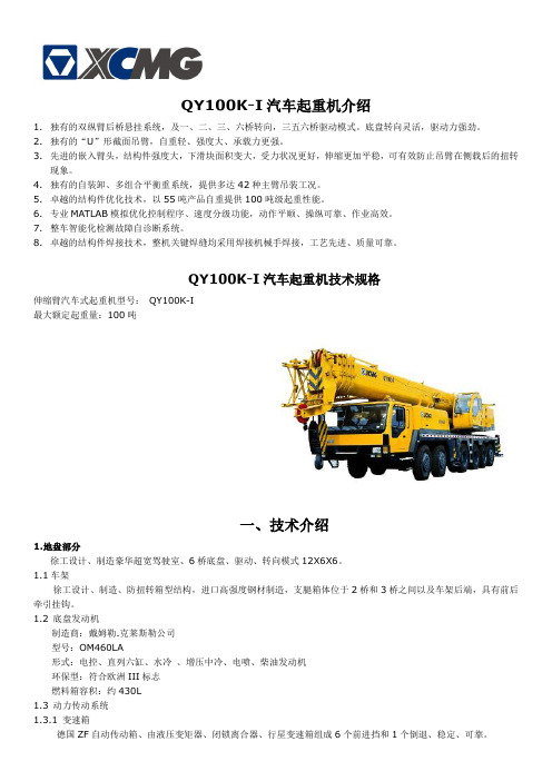
QY100K-I汽车起重机介绍1.独有的双纵臂后桥悬挂系统,及一、二、三、六桥转向,三五六桥驱动模式。
底盘转向灵活,驱动力强劲。
2.独有的“U”形截面吊臂,自重轻、强度大、承载力更强。
3.先进的嵌入臂头,结构件强度大,下滑块面积变大,受力状况更好,伸缩更加平稳,可有效防止吊臂在侧载后的扭转现象。
4.独有的自装卸、多组合平衡重系统,提供多达42种主臂吊装工况。
5.卓越的结构件优化技术,以55吨产品自重提供100吨级起重性能。
6.专业MATLAB模拟优化控制程序、速度分级功能,动作平顺、操纵可靠、作业高效。
7.整车智能化检测故障自诊断系统。
8.卓越的结构件焊接技术,整机关键焊缝均采用焊接机械手焊接,工艺先进、质量可靠。
QY100K-I汽车起重机技术规格伸缩臂汽车式起重机型号:QY100K-I最大额定起重量:100吨一、技术介绍1.地盘部分徐工设计、制造豪华超宽驾驶室、6桥底盘、驱动、转向模式12X6X6。
1.1车架徐工设计、制造、防扭转箱型结构,进口高强度钢材制造,支腿箱体位于2桥和3桥之间以及车架后端,具有前后牵引挂钩。
1.2 底盘发动机制造商:戴姆勒.克莱斯勒公司型号:OM460LA形式:电控、直列六缸、水冷、增压中冷、电喷、柴油发动机环保型:符合欧洲III标志燃料箱容积:约430L1.3 动力传动系统1.3.1 变速箱德国ZF自动传动箱、由液压变矩器、闭锁离合器、行星变速箱组成6个前进挡和1个倒退、稳定、可靠。
1.3.2 分动箱德国ZF、2挡、采取大输入扭矩,带差速锁。
1.3.3 桥高强度桥,维护简便。
第一桥:单胎,转向但不驱动;第二桥:单胎,转向但不驱动;第三桥:单胎,驱动、转向;第四桥:双胎,不驱动不转向;第五桥:双胎,驱动但不转向;第六桥:单胎,驱动转向。
1.3.4 传动轴驱动轴均采用端面齿连接,优化动力传输,传递扭矩大,维护简便,方便拆卸和安装。
1.4 桥悬挂前悬架,纵置板簧式,简式减振器,板簧与推力杆导向;后悬架,双轴平衡,纵置板簧式,板簧与推力杆导向;底盘的新悬挂机构,加大了车轮上下跳动量,提高了车辆的通过性。
工程机械常用液压泵马达多路阀

1
1.液压泵、马达、多路阀均有很多厂家和不同规格,不同功能,在此不能一一列举,只根据资料选取目前国内占有率最高的两三个厂家的主要产品进行列举。
应用场合以挖掘机和装载机为主。
2.普通板式阀主要参考力士乐和ATOS样本,根据国际ISO标准,囊括目前常用阀。
3.螺纹插装阀,根据查询资料总结,可知,目前国内螺纹插装阀主要标准为
JB/T5963.对其中各型号一一列举。
另国际上通用英制螺纹插装阀,最典型为VICKERS公司产品,故以其样本进行列举
4.二通插装阀只选取了40通径以下的,但试验台流量和最大工作压力不能满足插。
国内十大循环泵品牌行业十大循环泵公司总榜
国内十大循环泵品牌行业十大循环泵公司总榜1.上海阳光泵业制造有限公司上海阳光泵业是集设计/生产/销售泵、给水设备及泵用控制设备于一体的大型综合性泵业集团,是中国泵行业的龙头企业。
总资产达38亿元,在上海、浙江、河北、辽宁、安徽等省市拥有7家企业,5个工业园区,占地面积67万平方米,建筑面积35万平方米。
上海阳光获得了“上海市质量金奖”、“上海市科技百强企业”、“上海市名牌产品”、“中国质量信用AAA级”、“全国合同信用等级AAA级”、“质量、信誉、服务三优企业”、“中国最具竞争力的商品商标”、“五星级服务认证”等荣誉,连续多年入选全国机械500强。
高端人才和高素质的员工队伍是阳光发展的动力。
集团现有员工4500余人,其中工程技术人员500多名,主要由国内知名水泵专家教授、博士硕士、中高级工程师、高级工艺师组成,形成了具有创新思维的梯队型人才结构。
科技创新,是阳光基业长青的生命之源。
集团是上海市高新技术企业、上海市知识产权示范企业和上海市专利示范企业。
上海市级的“企业技术中心”,每年以销售总额的5%,用于技术创新和新产品研发。
2.河北仕航机械制造有限公司~河北仕航机械制造有限公司是齿轮泵、螺杆泵、转子泵、热油泵等产品专业生产加工的公司,拥有完整、科学的质量管理体系。
河北仕航机械制造有限公司的诚信、实力和产品质量获得业界的认可。
欢迎各界朋友莅临参观、指导和业务洽谈3.河北恒盛泵业股份有限公司河北恒盛泵业股份有限公司,原国营泊头市齿轮泵总厂,始建于一九七三年,齿轮泵行业标准制定单位。
恒盛泵业是以研发、制造“恒源”牌容积泵为主的国家二级企业、中石油物资资源市场a级供应商、中石化物资资源市场成员、国家高新技术企业、中通泵行业重点骨干企业、河北省名牌产品企业。
恒盛泵业于一九九七年在泵行业率先通过iso9001质量管理体系认证;二oo三年通过军品质量管理体系认证;二oo七年国防科工办授予我公司为舰船用泵研发生产基地、舰船用铸锻件生产基地。
派克汉尼汾工程机械用方向控制阀 L90LS 商品说明书
样本信息未使用本文所述之产品及相关项目选择不当或使用不当可能会造成人员死亡、警告样本布局除一般信息和基本技术数据外,该样本还对L90LS 可配置的选配功能做了描述。
我们可据此对L90LS 进行定制配置,以便以更佳的方式控制您的机器。
除一般信息和基本技术数据外,该样本还对阀门功能片中可配置的选配功能做了描述。
阀门的每个功能区域都有一个副标题,标题后面附有简短的描述。
如果某个功能区有多个不同的位置,则会在副标题的方括号内标注项目编号,例如[P16]溢流阀。
再接下来是一系列带有代号的选项,例如PA1、PS 、Y 以及每个代号的简短描述。
或者是一个或多个压力、流量或电压选项。
第8页的一般液压原理图中展示了L90LS 阀的基本功能区、以及代表这些功能区的条目编号。
有关L90LS 所有选项的信息,请参见样本MSG17-8504。
文档和订购L90LS 可在派克的在线产品配置器中根据客户的需求定制,定制规格通常在派克销售公司与客户协商后确定。
每个阀门配置都有唯一的ID 号、详细的代号报告、3D 模型、2D 图纸、备件清单、液压原理图、材料清单和装配说明。
除了前面提到的文档外,还登录XXXXX 观看每个选件的装配说明视频。
阀部件订购可使用物料清单通过派克销售公司进行。
尽早咨询,以节约时间和成本我们的工程师经验丰富,他们对不同类型的液压系统及其工作原理都有深入的了解。
他们可以帮助您选择符合要求的阀门。
我们建议在项目规划阶段尽早咨询派克。
派克保留修改产品的权利,恕不另行通知。
本样本中使用了典型的曲线和图表。
即使样本不断修订和更新,也不可避免存在出错的可能。
请联系派克汉尼汾,了解更多有关产品的详细信息。
概述 (4)技术数据 (5)压力 (5)内部先导压力 (5)通流流量 (5)重量 (5)过滤 (5)液压油 (5)温度 (5)[P03] 泵调节器设置 (6)油口 (6)[P04] 接口螺纹 (6)进口片 (6)工作片 (6)出口片 (6)液压原理图 (7)进口片 (8)[P15-P29] 进口片 (8)[P15] 进口片 (8)用于[P15] CFC、LS1进口片 (9)[P16] 溢流阀 (9)[P17] 压力设定 (9)用于[P15] LS2进口片 (9)[P16] 泄压阀 (9)[P17] 压力设定 (9)[P20] 负载信号系统 (10)[P25] 回油口T1 (10)[P26] 进油口P1 (10)出口片 (11)[P30 - P44] 出口片 (11)[P30] 出口片 (11)用于出口片[P30] US (12)[P31] LS油口 (12)[P32] 进油口P2 (12)[P33] 背压阀/回油口T2 (12)[P34] 回油口T3 (12)[P37] 内部先导压力供油 (12)[P39] 先导过滤器 (12)[P40] 回油口,用于先导回路..............................................12工作片.. (13)[P45-P89] 工作片 (13)[P47] 工作片的基本变型 (13)[P50] 阀芯执行器 (14)比例远程控制阀芯执行器,带封闭阀芯端 (14)比例远程控制阀芯执行器,带封闭阀芯端 (15)比例远程控制阀芯执行器,带封闭阀芯端 (16)手动控制阀芯执行器,带封闭阀芯端 (17)[P51] 手柄支架 (17)[P55A,B] 先导节流器 (18)[P56] 插头类型 (18)[P60] 阀芯功能 (19)[P64A, B] 力反馈 (20)[P66]压力补偿器/负载保持单向阀 (20)[P69] 阀芯名称 (21)[P71A,B] 工作油口公称流量 (21)[P72] 流量设定 (21)[P72A] 所需的设定流量 (21)[P72B] 所需的设定流量 (21)[P75] 进给减压阀 (21)[P75A] A油口的进给减压设定 (21)[P75B] B油口的进给减压设定 (21)[P76A,B] 油口溢流阀和/或防气穴阀 (22)信息 (23)[P50] EC2手动越权 (23)尺寸图 (24)备件 (25)L90LS具有四个工作段。
Parker Push-Lok 801 804 821 836 管筒与附配件说明说明书
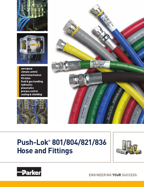
Hose and FittingsParker Push-Lok® – The Most Complete Line of Premium-Quality, Low-Pressure Hose and FittingsParker’s Push-Lok Plusmultipurpose hose line featuresthe widest fluid compatibility,application range and size range inthe industry. It also incorporatesthe highest working pressure in allsizes, making it the most versatilegeneral-purpose hose available.Easy Assembly andOrganizationThe Push-Lok system is easy touse. No clamps or special toolsare required during installation.And with Parker’s exclusive color-code system, you can inventory,maintain and identify your hoseneeds easily and efficiently.Exceptional Value and SavingsParker Push-Lok assembliescan be made in seconds, savingvaluable time and cost.And, Push-Lok 82 Series fittingsare reusable. You can replace thehose at the job site without anyspecial tools or clamps.Operational IntegrityHelping you maintain a cleanwork environment is anotherimportant reason to use Parker’sPush-Lok system. Its unique sealensures reliable, durable,leak-free service.Outstanding quality, valuableefficiency and Parker’s leak-freeassurance are what you get withevery Parker Push-Lok hose andfitting system. The industry’s mostcomplete line of low-pressurehose and fittings, Push-Lok offersthe range and versatility to meetall your needs.The “Push-Lok” BenefitsPush-Lok Plus 801 hose providesthe quick and easy assembly/disassembly advantage and thefullest range of color-codingto benefit your operations.It’s now approved with both 82Series push-on and HY Seriescrimp fittings.Push-Lok Plus 804 hose featuresquick and easy assembly andprovides an EPDM inner-tubefor hot water, dry air andphosphate- ester fluids.Push-Lok 821 is a higherpressure multipurpose hosethat is widely used for shop airsystems and general industrialand maintenance applications.It’s approved with 82 Seriesfittings, and is also available witha fire resistant (FR) cover for usenear welding operations.Push-Lok Plus 836 delivershigh temperature up to 302°F,heat-resistant performance andhigher working pressures than821, along with the same HY and82 Series fittings compatibility.Fiber braid reinforcement layer High-quality elastomer cover —The Color-Coded AdvantagesImproved Inventory ControlAssign a Push-Lok color to each department for its maintenance requirements. The color system helps assure that hoses are routed to their correct areas, resulting in better control over hose inventories.Identifying Industrial Drop LinesUse Push-Lok colors to identify drop line length and diameter for faster and easier replacement. When replacing by color, the right size and length are automatically set.Easier, Faster Line IdentificationIn applications where a number of hose lines carry different media, Push-Lok colors reduce timely “tracing” of lines, preventing disconnection of the wrong line and unnecessary, costly downtime.More Efficient Preventive MaintenanceUsing color-coded Push-Lok hose is an excellent way to keep track of scheduled replacement of low-pressure hose in youroperations. Just assign a different color hose to each replacement period and eliminate the possibility of missing lines scheduled for replacement.Enhanced Product AppearanceFor equipment manufacturers and their customers, using Push-Lok color hoses can vastly improve the visual and functional appeal of work equipment, on-line systems and the overall facility.*For pressure values in bars, multiply the Mpa value times 10. For pressure values in kPa, multiply the Mpa value times 1000. For pressure values in kgf/cm 2, multiply the Mpa value times 10,2.801PartWorkingMinimumField NumberHose I.D. Hose O.D. Pressure Bend Radius Weight Parkrimp Attachableinch mminch mmpsi MPainch mmlbs/ft kg/mHY Series82 SeriesColor CodesGRA RED YEL BLU GRN BLKColor CodesBLKColor CodesBLK801-4 1/4 6,3 0.50 12,7 350 2,4 2-1/2 65 0.09 0,13 • •801-6 3/8 10 0.63 15,9 350 2,4 3 75 0.11 0,16 • •801-8 1/2 12,5 0.78 19,8 300 2,1 5 125 0.18 0,27 • •801-10 5/8 16 0.91 23,0 300 2,1 6 150 0.19 0,28 • •801-12 3/4 19 1.03 26,2 300 2,1 7 180 0.24 0,36 • •801-161251.2832,62001,4102500.370,55••836PartWorkingMinimumFieldNumberHose I.D. Hose O.D. Pressure Bend Radius Weight Parkrimp Attachableinch mminch mmpsi MPainch mmlbs/ft kg/mHY Series82 SeriesColor CodesBLU836-4 1/4 6,3 0.50 12,7 400 2,8 2-1/2 65 0.09 0,13 • •836-6 3/8 10 0.63 15,9 400 2,8 3 75 0.11 0,16 • •836-8 1/2 12,5 0.78 19,8 400 2,8 4 125 0.18 0,27 • •836-10 5/8 16 0.91 23,0 350 2,4 5 150 0.19 0,28 • •836-123/4191.0326,23002,161800.240,36••804PartWorkingMinimumVacuum Rating FieldNumberHose I.D. Hose O.D. Pressure Bend Radius WeightAttachableinch mminch mmpsi MPainch mmlbs/ft kg/m 82 Series804-4 1/4 6,3 0.50 12,7 150 1,7 2-1/2 65 0.09 0,13 15 51 •804-6 3/8 10 0.63 15,9 150 1,7 3 75 0.11 0,16 15 51 •804-8 1/2 12,5 0.78 19,8 100 1,7 5 130 0.18 0,27 15 51 •804-10 5/8 16 0.91 23,0 100 1,0 6 150 0.19 0,28 15 51 •804-123/4191.0326,21001,771800.240,3615 51•Hgof HG kPa inches 821PartWorkingMinimumVacuum Rating FieldNumberHose I.D. Hose O.D. Pressure Bend Radius WeightAttachableinch mminch mmpsi MPainch mmlbs/ft kg/m 82 Series821-4 1/4 6,3 0.50 12,7 350 2,4 2-1/2 64 0.06 0,09 28 95 •821-6 3/8 10 0.63 15,9 300 2,1 3 76 0.09 0,13 28 95 •821-8 1/2 12,5 0.78 19,8 300 2,1 5 127 0.12 0,18 28 95 •821-10 5/8 16 0.91 23,0 250 1,7 6 152 0.19 0,28 28 95 •821-123/4191.0326,22501,771780.210,3128 95•Hgof HG kPa inchesPartWorkingMinimumVacuum Rating FieldNumberHose I.D. Hose O.D. Pressure Bend Radius WeightAttachableinch mminch mmpsi MPainch mmlbs/ft kg/m 82 Series821FR-4 1/4 6,3 0.50 12,7 350 2,4 2-1/2 64 0.08 0,12 28 95 •821FR-6 3/8 10 0.63 15,9 300 2,1 3 76 0.11 0,16 28 95 •821FR-8 1/2 12,5 0.78 19,8 300 2,1 5 127 0.12 0,18 28 95 •821FR-123/4191.0326,22501,771780.220,3328 95•821FRColor CodesWHT BRN BLU GRN BLKHgof HG kPa inchesAssembly and Disassembly Steps Assembly is easy1.Cut hose cleanly and squarelywith a sharp knife or a ParkerPush-Lok cut-off tool2. Lubricate the Push-Lok fittingand/or Hose I.D. with a light oilor soapy water only. Do notuse heavy oil or grease.3.Insert fitting into hose untilthe barb is in the hose.4.Place end fitting against aflat object (bench or wall).Grip hose approximately oneinch from end and push withsteady force until the end ofthe hose bottoms on the fittingand is covered by the yellowplastic cap.Disassembles fast1.Leave fitting in place andcut hose lengthwise fromthe yellow cap approximatelyone inch. IMPORTANT: Becareful not to nick barbswhen cutting hose.2.Grip hose and give a sharpdownward tug to disengagethe fitting.Caution: Push-Lok fittings will properly grip Push-Lok hose only when pushed all the wayin with the cut end of the hose completely concealed by the yellow plastic cap.Sealing integrity may be damagedby using exterior clamps.4 poundsField Attachable**367823J9823B2823C4823J7823C5823698233982379823378234182For use with Parkrimp style crimpers.179HY139HY141HY193HY10LHY11LHY1J9HY1J1HY 169HYParker Fluid Connectors GroupNorth American Divisions & Distribution Service CentersYour complete source for quality tube fittings, hose& hose fittings, brass & composite fittings, quick-disconnect couplings, valves and assembly tools, locally available from a worldwide network of authorized distributors.Fittings:Available in inch and metric sizes covering SAE, BSP, DIN, GAZ, JIS and ISO thread configurations, manufactured from steel, stainless steel, brass, aluminum, nylon and thermoplastic.Hose, Tubing and Bundles: Available in a wide variety of sizes and materials including rubber, wire-reinforced, thermoplastic, hybrid and custom compounds. Worldwide Availability: Parker operates Fluid Connectors manufacturing locations and sales offices throughout North America, South America, Europe and Asia-Pacific.For information, call toll free... 1-800-C-PARKER(1-800-272-7537)North American DivisionsEnergy Products DivisionStafford, TXphone 281 566 4500fax 281 530 5353Fluid System ConnectorsDivisionOtsego, MIphone 269 694 9411fax 269 694 4614Hose Products DivisionWickliffe, OHphone 440 943 5700fax 440 943 3129Industrial Hose DivisionStrongsville, OHphone 440 268 2120fax 440 268 2230Parflex DivisionRavenna, OHphone 330 296 2871fax 330 296 8433Quick Coupling DivisionMinneapolis, MNphone 763 544 7781fax 763 544 3418Tube Fittings DivisionColumbus, OHphone 614 279 7070fax 614 279 7685Distribution Service CentersBuena Park, CAphone 714 522 8840fax 714 994 1183Conyers, GAphone 770 929 0330fax 770 929 0230Lakeville, MNphone 952 469 5000fax 952 469 5729Louisville, KYphone 502 937 1322fax 502 937 4180Portland, ORphone 503 283 1020fax 503 283 2201Toledo, OHphone 419 878 7000fax 419 878 7001fax 419 878 7420(FCG Kit Operations)CanadaGrimsby, ONTphone 905 945 2274fax 905 945 3945(Contact Grimsby for otherService Center locations.)Push-Lok is a registered trademark of Parker Hannifin Corp.© 2011 Parker Hannifin CorporationParker Hannifin CorporationFluid Connectors GroupHose Products Division30240 Lakeland BoulevardWickliffe, OH 44092phone440 943 5700fax440 943 3129*************************4281-B1 5/2011。
Parker CO Series 单向阀门目录说明书

Check Valves (CO Series)Catalog 4130-CORevised, October 1999IntroductionParker CO Series Check Valves are designed for uni-directional flow control of fluids and gases in industries such as chemical processing, oil and gas production and transmission, pharmaceutical, pulp and paper, power and utilities. The CO Series Check Valve is particularly suitable for applications requiring high integrity leak rates and re-sealing capabilities.Materials of ConstructionModel Shown: 4V-CO4L-5-V-SS2Features•Seal integrity across the seat and to atmosphere is tested to 4 x 10⁻⁹ std atm-cc/sec (4 x 10⁻¹⁰ kPa – L/sec) for the CO4L with fluorocarbon rubber seals. All other sizes and seal materials are tested to 1 x 10⁻⁵ std atm-cc/sec (1 x 10⁻⁶ kPa – L/sec).•Special seat seal design provides a repeatable high integrity seal and accurate cracking pressures •100% factory tested. Cracking pressures include:1/3, 1, 5, 10, 25, 50, 75, and 100 psi.•Valves are available with Male and Female NPT, CPI TM ,A-LOK ®, UltraSeal, Male and Female VacuSeal, and Tube Adapter•Heat code traceability•Color coded identification labels indicate seal materialSpecifications•Pressure Rating:6000 psig CWP (414 bar)•Temperature Rating:Fluorocarbon Rubber-10 °F to 400 °F (-23 °C to 204 °C)Buna-N Rubber-30 °F to 250 °F (-34 °C to 121 °C)Ethylene Propylene Rubber-70 °F to 275 °F (-57 °C to 135 °C)Highly Fluorinated Fluorocarbon Rubber-20 °F to 200 °F (-29 °C to 93 °C)•Orifice: .156" to .406" (4.0mm to 10.3mm)•Cv Factor: .43 to 2.65Flow Calculations with 1000 psig (69 bar) Inlet PressureParker Hannifin CorporationInstrumentation Valve Division Jacksonville, AlabamaA479, TYPE 316L.2Optional seal materials are available. See How to Order section.Lubrication: Perfluorinated Polyether3Label Color Cross ReferenceTesting: All valves are 100% tested for crack, re-seal, and D = Hex of nuts where applicable Model Shown: 4V-CO4L-5-KZ-SSParker Hannifin Corporation Instrumentation Valve Division Jacksonville, Alabama‡Tested in accordance with ISA S75.02. Gas flow will be choked when P 1 - P 2 I P 1 = x T.WARNINGFAILURE, IMPROPER SELECTION OR IMPROPER USE OF THE PRODUCTS AND/OR SYSTEMS DESCRIBED HEREIN OR RELATED ITEMS CAN CAUSE DEATH, PERSONAL INJURY AND PROPERTY DAMAGE.This document and other information from Parker Hannifin Corporation, its subsidiaries and authorized distributors provide product and/or system options for further investigation by users having technical expertise. It is important that you analyze all aspects of your application and review the information concerning the product or system in the current product catalog. Due to the variety of operating conditions and applications for these products or systems, the user, through its own analysis and testing, is solely responsible for making thefinal selection of the products and systems and assuring that all performance, safety and warning requirements of the application are met.The products described herein, including without limitation, product features, specifications, designs, availability and pricing, are subject to change by Parker Hannifin Corporation and its subsidiaries at any time without notice.How To OrderThe correct part number is easily derived by following the circled number sequence.The six product characteristics required are coded as shown below. *Note: If both the inlet and outlet ports are the same, eliminate the outlet port designator.Example :----Port PortSizePressure Material MaterialDescribes a CO Series Check Valve with 1/4" male NPT inlet and a 1/4" female NPT outlet, 1 psig cracking pressure,4Offer of SaleThe items described in this document are hereby offered for sale by Parker Hannifin Corporation, its subsidiaries or its authorized distributors. This offer and its acceptance are governed by the provisions stated in the “Offer of Sale” located in Catalog 4103 Instrumentation Valve Technical Guide.© Copyright 1999, Parker Hannifin Corporation. All Rights Reserved.A -Two ferrule A-LOK ®compression portAvailable End ConnectionsF -ANSI/ASME B1.20.1Internal pipe threadsM -ANSI/ASME B1.20.1External pipe threadsZ -Single ferrule CPI TM compression portV -VacuSeal face seal port Q -UltraSeal face seal portV1-Internal VacuSeal face seal portCO Series Check ValvesParker Hannifin Corporation Instrumentation Valve Division Jacksonville, AlabamaTA -Tube adapter connectionOptionsOxygen Cleaning - Add the suffix -C3 to the end of the part number to receive valves cleaned and assembled for oxygen service in accordance with Parker specification ES8003. Example: 4A-CO4L-1-BN-SS-C3Special Cleaning - All face seal ended valves are cleaned in accordance with Parker Specification ES8001. This is an option for all valves by adding the suffix -C1 to the end of the part number. Example: M6A-CO4L-10-SS-C1Material - Contact the factory for availability of AOD/VAR stainless steel and ID Electropolish.5Note: To determine MPa, multiply bar by 0.1CO Series Check ValvesParker Hannifin Corporation Instrumentation Valve Division Jacksonville, AlabamaBCP means “Below Cracking Pressure”Cracking pressure is defined as the upstream pressure at which a detectable flow is measured.Re-seal pressure is defined as the upstream pressure at which the check valve closes bubble-tight.Example: For a valve with a spring having a rated crackingpressure of 25 psig, (1.72 bar) the actual cracking pressure ranges between 20 and 30 psig (1.38 and 2.07 bar). The re-seal pressure range would be 16 to 20 psig (1.10 to 1.38 bar).Check valves having springs with rated crack pressures of 3psig (0.21 bar) or less may require up to 4 psig (0.28 bar) back pressure to re-seal bubble-tight.Note: Check valves which are not actuated for a period of time may initially crack at higher than the above crack pressure ranges.Parker Hannifin CorporationInstrumentation Valve Division2651 Alabama Highway 21 NorthJacksonville, AL 36265-9681Phone: (256) 435-2130Fax: (256) 435-7718/IVDCatalog 4130-CO, 20M, 10/99。
Parker Hannifin 方向控制阀 Series M402LS 零部件清单说明书
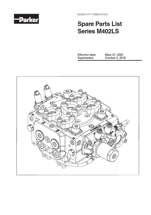
Effective date: Mars 27, 2020Supersedes: October 2, 2018Bulletin HY17-8860-M1/UKSpare Parts ListSeries M402LS2Parker Hannifin ABMobile Controls Division Europe Boras, SwedenDirectional Control Valves Series M402LSBulletin HY17-8860-M1/UKSpare Parts ListOffer of SalePlease contact your Parker representation for a detailed ”Offer of Sale”.Conversion factors1 kg = 2.2046 lb 1 N = 0.22481 lbf 1 Nm = 0.10197 kpm 1 bar = 14.504 psi 1 l = 0.21997 UK gallon 1 l = 0.26417 US gallon 1 cm 3 = 0.061024 in 31 m = 3.2808 feet 1 mm= 0.03937 in1°C = (9/5xC°+32)°FThis list of spare parts is designed to give you a good idea of the components included in the product range for valves. To see precisely which component is used for a specific product, you will need to look at the customer specification for the product in question. The customer specification contains a number of entries, and for each entry, a code pressure or flow is specified with a code or a number. To help you find your way around, this list of spare parts contains r eferences to these entries and codes.Codes on the image page of the list of spare parts usually appear in bold and enclosed in a border. The table page contains available spare part sets. The ordering code is the product code that appears in the Part column.The spare part to be used is determined by the first two columns, which c ontain the entry and the code from the customer specification. If these c olumns are empty, the spare part set is valid regardless of the selected code, unless indicated otherwiseThe symbols in the frame below are used in this Spare Parts List to help you find the right tools, the right torques, suitable grease etc.Technical index description1 = Item pos. no. 1.1(2x) = Item pos. no. 1, contains 2 pieces in the kit 1[2] = Item pos. no. 2 already mounted on item pos. no. 1 at delivery.1[2](2x) = Item pos. no. 1 (see above) contains 2 pieces in the kit.3Parker Hannifin ABMobile Controls Division Europe Boras, SwedenDirectional Control Valves Series M402LSBulletin HY17-8860-M1/UKContentsDesignationCustomer ordered markingSerial numberValve serial numbers consist of three groups of digits The first group shows year and week of manufacture:In this example, 1534 means week 34 of 2015The remaining digits are for internal use within ParkerList of contentsMain Block ............................................................................................PA, PAY, Y2, X2, N2, X3, N, MX, MF5, MF9, LD, A264,A08,A417 4PAY, X3, N, A264,A417 ..................................................................6PR1, plugs, A05.............................................................................8Spool Actuator .....................................................................................PC, FPC, A03 ..............................................................................10EC, 12, 24, A, D, 0.8 to 2.0, A03 .................................................12FEC, 12, 24, A, D, 0.8 to 2.0, A03 ...............................................14Main Block . (16)Connection flanges, FPC, EPC, PC, EC .....................................16Appendix A Warnings ......................................................................18Appendix B: EC+FEC; PC+FPC ......................................................19Appendix D: Phased out .................................................................20Appendix Z: Change history .. (21)4Parker Hannifin ABMobile Controls Division Europe Boras, SwedenDirectional Control Valves Series M402LSBulletin HY17-8860-M1/UKMain Block5Parker Hannifin ABMobile Controls Division Europe Boras, SwedenDirectional Control Valves Series M402LSBulletin HY17-8860-M1/UKMain Block6Parker Hannifin ABMobile Controls Division Europe Boras, SwedenDirectional Control Valves Series M402LSBulletin HY17-8860-M1/UKMain BlockPAY, X3, N, A264,A4177Parker Hannifin ABMobile Controls Division Europe Boras, SwedenDirectional Control Valves Series M402LSBulletin HY17-8860-M1/UKMain BlockSee Customer Specification CodePosPartDescriptionRemarks / ItemsN 54A, 54B 6763282Supply check valve 23, 24N 54A, 54B 6764407Supply check valve, cpl., N 23, 24, 26N, X354A, 54B 6764406 Plug X326X354A, 54B 6760295Cavity plug X347N 54A, 54B 6760680Sequence valve 46A26454A, 54B 6760624Sequence valve A26446N, X3, A26454A, 54B 302000K805Seal kit N, X3, A264Not shown A41735A,35B 55A, 55B6764135Plug M42x2-M14x1,5, A41711[10]Pressure relief valve PAY. See page 4.8Parker Hannifin ABMobile Controls Division Europe Boras, SwedenDirectional Control Valves Series M402LSBulletin HY17-8860-M1/UKMain BlockPR1, plugs, A0587866 or 1/4”9Parker Hannifin ABMobile Controls Division Europe Boras, SwedenDirectional Control Valves Series M402LSBulletin HY17-8860-M1/UKMain BlockSee Customer Specification CodePosPartDescriptionRemarks / ItemsPR1 + M6, M316 + 09397000K007LS/Prio, check valve 38, 39PR1 + U6, U316 + 096760287LS/Prio, check valve38, 39A05 + U6, U3166760288Without prio function, UNF , (A05)39, 86, 87A05 + M6, M316397001K100Without prio function, metric, (A05)39, 86, 87PR1, A0516*******Restrictor Ø0.6 mm 79(5x)PR1, A0516–Plug VSTI10x1EDCF 42M6, M309–Plug VSTI14x1.5EDCF 39U6, U309–Plug 6HP5ON-S 39–Plug, VSTI10x1EDCF 426760017M6 plug kit 48(2x), 49(2x)–Plug 8HP5ON-S 50–Plug 12HP5ON-S 51PC, EC + M3, M627/47 + 09–Plug VSTI14x1.5EDCF 39PC, EC + U3, U627/47 + 09–Plug 6HP5ON-S3910Parker Hannifin ABMobile Controls Division Europe Boras, SwedenDirectional Control Valves Series M402LSBulletin HY17-8860-M1/UKSpool ActuatorPC, FPC, A03M6/U6 PC+FPC cap B-side updated with new design.These options are fully replacable.See Appendix BSee Customer SpecificationCode Pos Part Description Remarks / ItemsM6, M309–Plug VSTI14x1.5EDCF39U6, U309–Plug 6HP5ON-S39PC/EC27397000K032Spring package (6-18) bar, STD35A0314397001K102Spring package (8-24) bar (A03)35PC + PC27 + 476760282Seal kit, intersection53(4x), 54(5x)PC + PC + M6, M327 + 47 + 096760276Cap kit, A-side, metric39, 53(2x), 54(2x), 55(6x), 56PC + PC + U6, U327 + 47 + 096760277Cap kit, A-side, UNF39, 53(2x), 54(2x), 55(6x), 56PC + PC + M6, M327 + 47 + 096760511Cap kit, B-side, metric53(2x), 54(2x), 55(6x), 85PC + PC + U6, U327 + 47 + 096760512Cap kit, B-side, UNF53(2x), 54(2x), 55(6x), 85PC + FPC27 + 476760282Seal kit, intersection53(4x), 54(5x)PC + FPC + M627 + 47 + 096760276Cap kit, A-side, metric53(2x), 54(2x), 55(6x), 56PC + FPC + U627 + 47 + 096760277Cap kit, A-side, UNF53(2x), 54(2x), 55(6x), 56PC + FPC + M627 + 47 + 096764293Cap kit, B-side, metric53(2x), 54(3x), 55(6x), 62 [39(2x), 58,61], 69PC + FPC + U627 + 47 + 096764294Cap kit, B-side, UNF53(2x), 54(3x), 55(6x), 62 [39(2x), 58,61], 69PC + FPC27 + 476763170Sign 'WARNING'69PC + FPC + M627 + 47 + 096760283Hose float position, metric59, 60(2x)PC + FPC + U627 + 47 + 096760284Hose float position, UNF59, 60(2x)FPC476760265Float position spring pack61FPC47–Plug VSTI48x2EDCF58PC + FPC + M627 + 47 + 09–Nipple 6M14F82EDMLOS60PC + FPC + U627 + 47 + 09–Nipple 6F50MLOS60EC, 12, 24, A, D, 0.8 to 2.0, A03M6/U6 EC+EC cap B-side replacedby M3/U3 EC+EC cap.These options are fully replacable.See Appendix D.See Customer SpecificationCode Pos Part Description Remarks / ItemsEC/PC27397000K032Spring package (6-18) bar, STD35A0314397001K102Spring package (8-24) bar (A03)35EC27, 476760282Seal kit, intersection53(4x), 54(5x)M3, M609–Plug VSTI14x1.5EDCF39U3, U609–Plug 6HP5ON-S39M6, U609–Plug VSTI48x2EDCF58EC + EC + M3, M627 + 47 + 096760274Cap kit, A-side, metric39(3x), 53(2x), 54(2x), 55(6x), 64 EC + EC + U3, U627 + 47 + 096760275Cap kit, A-side, UNF39(3x), 53(2x), 54(2x), 55(6x), 64 EC + EC + M3, M627 + 47 + 096760509Cap kit, B-side, metric53(2x), 54(2x), 55(6x), 86 [39 (3x),60]EC + EC + U3, U627 + 47 + 096760510Cap kit, B-side, UNF53(2x), 54(2x), 55(6x), 86 [39 (3x),60]EC + EC + M3, M627 + 47 + 096760285Hose kit, metric60(2x), 68EC + EC + U3, U627 + 47 + 096760286Hose kit, UNF60(2x), 6812 + A03 + 046763059Solenoid valve PS25 12 VDC, AMP65, 66(2x)24 + A03 + 046763060Solenoid valve PS25 24 VDC, AMP65, 66(2x)12 + D03 + 046763061Solenoid valve PS25 12 VDC,Deutsch88, 66(2x)24 + D03 + 046763062Solenoid valve PS25 24 VDC,Deutsch88, 66(2x)0.828A, 28B,48A, 48B 6760326Restrictor Ø0.8 mm63(5x)1.56760325Restrictor Ø1.5 mm63(5x)2.0398000K603Restrictor Ø2.0 mm63(5x)EC + EC27 + 476760507Seal kit PS25Set of 5 (for items 65 and 88)EC + EC + M3, M627 + 47 + 09-Nipple 6M14F82EDMLOS60EC + EC + U3, U627 + 47 + 09-Nipple 6F50MLOS60FEC, 12, 24, A, D, 0.8 to 2.0, A03M6/U6 EC+FEC cap B-sideupdated with new design.These options are fully replacable.See Appendix BSee Customer SpecificationCode Pos Part Description Remarks / Items -14397000K032Spring package (6-18) bar, STD35A0314397001K102Spring package (8-24) bar (A03)35FEC476760282Seal kit, intersection53(4x), 54(5x)M609–Plug VSTI14x1.5EDCF39U609–Plug 6HP5ON-S39M6, U609–Plug VSTI48x2EDCF58EC + FEC + M627 + 47 + 096760274Cap kit, A-side, metric39(3x), 53(2x), 54(2x) 55(6x), 64EC + FEC + U627 + 47 + 096760275Cap kit, A-side, UNF39(3x), 53(2x), 54(2x) 55(6x), 64EC + FEC + M627 + 47 + 096764291Cap kit, B-side, metric53(2x), 54(3x) 55(6x), 67 [39(3x), 58,60, 61], 69EC + FEC + U627 + 47 + 096764292Cap kit, B-side, UNF53(2x), 54(3x) 55(6x), 67 [39(3x), 58,60, 61], 69EC + FEC27 + 476763170Sign 'WARNING'69FEC476760265Float position spring pack61EC + FEC + M627 + 47 + 096760285Hose kit60(2x), 68EC + FEC + U627 + 47 + 096760286Hose kit60(2x), 68EC + FEC + M627 + 47 + 096760283Hose float position59, 60(2x)EC + FEC + U627 + 47 + 096760284Hose float position59, 60(2x)12 + A03 + 046763059Solenoid valve PS25 12 VDC, AMP65, 66(2x)24 + A03 + 046763060Solenoid valve PS25 24 VDC, AMP65, 66(2x)12 + D03 + 046763061Solenoid valve PS25 12 VDC, Deutsch88, 66(2x)24 + D03 + 046763062Solenoid valve PS25 24 VDC, Deutsch88, 66(2x)0.828A, 28B,48A, 48B 6760326Restrictor Ø0.8 mm63(5x)1.56760325 Restrictor Ø1.5 mm63(5x)2.0398000K603Restrictor Ø2.0 mm63(5x)EC + FEC27 + 476760507Seal kit PS25Set of 5 (for items 65 and 88)EC + FEC + M627 + 47 + 09-Nipple 6M14F82EDMLOS60EC + FEC + U627 + 47 + 09-Nipple 6F50MLOS60Connection flanges, FPC, EPC, PC, ECSee Customer SpecificationCode Pos Part Description Remarks / Items M3, U3, M6,U6096760299Clamp kit 3000 psi69(4x), 70(2x)M3, U3096760297Clamp kit 3000 psi73(4x), 74(2x)M6, U6096760296Clamp kit 6000 psi73(4x), 74(2x)M3, U3096760297Clamp kit 3000 psi71(4x), 72(2x)M6, U6096760298Clamp kit 6000 psi71(4x), 72(2x)M3, U3 + EA09 + 21, 416760279Work port blocked, 3000 psi73(4x), 74(2x), 80, 81 M6, U6 + EA09 + 21, 416760278Work blocked, 6000 psi73(4x), 74(2x), 80, 81PC + PC; EC + EC27 + 47302000K059Pin kit75PC + FPC; EC + FEC27 + 47302000K058Sequence function spool kit76, 77, 78M3, M609–Plug VSTI14x1.5EDCF39U3, U609–Plug 6HP5ON-S39Appendix B: EC+FEC; PC+FPCOld style, kit 6760266, 6760267Old style, kit 6760268, 6760269New style, kit 6764293, 6764294New style, kit 6764291, 6764292EC+FECPC+FPCAppendix D: Phased out24Replaced by spool actuator EC+EC M3/U3Replaced by spool actuator PC+PC M3/U321Parker Hannifin ABMobile Controls Division Europe Boras, SwedenDirectional Control Valves Series M402LSBulletin HY17-8860-M1/UKPageCodeKit DescriptionOld kit2--Symboles for servicing, Tighting torque tolerance.-3--Label according to MTB 9119-5N 6763175Supply check valve, cpl., N 67644075N, X36761034Plug X367644067N 6763175Supply check valve, cpl., N 67644077N, X36761034Plug X36764406Appendix Z: Change history22Parker Hannifin ABMobile Controls Division Europe Boras, SwedenDirectional Control Valves Series M402LSBulletin HY17-8860-M1/UKNotes23Parker Hannifin ABMobile Controls Division Europe Boras, SwedenDirectional Control Valves Series M402LSBulletin HY17-8860-M1/UKNotesYour local authorized Parker distributorParker WorldwideEurope, Middle East, AfricaAE – United Arab Emirates, DubaiTel: +971 4 8127100********************AT – Austria, St. FlorianTel: +43 (0)7224 66201*************************AZ – Azerbaijan, BakuTel: +994 50 2233 458****************************BE/NL/LU – Benelux,Hendrik Ido AmbachtTel: +31 (0)541 585 000********************BG – Bulgaria, SofiaTel: +359 2 980 1344**************************BY – Belarus, MinskTel: +48 (0)22 573 24 00************************CH – Switzerland, EtoyTel: +41 (0)21 821 87 00*****************************CZ – Czech Republic, KlecanyTel: +420 284 083 111*******************************DE – Germany, KaarstTel: +49 (0)2131 4016 0*************************DK – Denmark, BallerupTel: +45 43 56 04 00*************************ES – Spain, MadridTel: +34 902 330 001***********************FI – Finland, VantaaTel: +358 (0)20 753 2500*************************FR – France, Contamine s/ArveTel: +33 (0)4 50 25 80 25************************GR – Greece, PiraeusTel: +30 210 933 6450************************HU – Hungary, BudaörsTel: +36 23 885 470*************************IE – Ireland, Dublin Tel: +353 (0)1 466 6370*************************IL – Israel Tel: +39 02 45 19 21************************IT – Italy, Corsico (MI) Tel: +39 02 45 19 21***********************KZ – Kazakhstan, Almaty Tel: +7 7273 561 000****************************NO – Norway, Asker Tel: +47 66 75 34 00 ************************PL – Poland, Warsaw Tel: +48 (0)22 573 24 00 ************************PT – Portugal Tel: +351 22 999 7360 **************************RO – Romania, Bucharest Tel: +40 21 252 1382 *************************RU – Russia, Moscow Tel: +7 495 645-2156 ************************SE – Sweden, Borås Tel: +46 (0)8 59 79 50 00 ************************SK – Slovakia, Banská Bystrica Tel: +421 484 162 252 **************************SL – Slovenia, Novo Mesto Tel: +386 7 337 6650 **************************TR – Turkey, Istanbul Tel: +90 216 4997081 ************************UA – Ukraine, Kiev Tel: +48 (0)22 573 24 00 ************************UK – United Kingdom, Warwick Tel: +44 (0)1926 317 878 ********************ZA – South Africa, Kempton Park Tel: +27 (0)11 961 0700 *****************************North AmericaCA – Canada, Milton, Ontario Tel: +1 905 693 3000US – USA, Cleveland Tel: +1 216 896 3000Asia PacificAU – Australia, Castle Hill Tel: +61 (0)2-9634 7777CN – China, Shanghai Tel: +86 21 2899 5000HK – Hong Kong Tel: +852 2428 8008IN – India, MumbaiTel: +91 22 6513 7081-85JP – Japan, Tokyo Tel: +81 (0)3 6408 3901KR – South Korea, Seoul Tel: +82 2 559 0400MY – Malaysia, Shah Alam Tel: +60 3 7849 0800NZ – New Zealand, Mt Wellington Tel: +64 9 574 1744SG – Singapore Tel: +65 6887 6300TH – Thailand, Bangkok Tel: +662 186 7000TW – Taiwan, Taipei Tel: +886 2 2298 8987South AmericaAR – Argentina, Buenos Aires Tel: +54 3327 44 4129BR – Brazil, Sao Jose dos Campos Tel: +55 800 727 5374 CL – Chile, Santiago Tel: +56 2 623 1216MX – Mexico, Toluca Tel: +52 72 2275 4200© 2019 Parker Hannifin Corporation. All rights reserved.EMEA Product Information Centre Free phone: 00 800 27 27 5374(from AT , BE, CH, CZ, DE, DK, EE, ES, FI, FR, IE, IL, IS, IT , LU, MT , NL, NO, PL, PT , RU, SE, SK, UK, ZA) US Product Information Centre Toll-free number: 1-800-27 27 537E d . 2020-02-14。
美国进口阿土祖控制阀多路阀

美国进口阿土祖控制阀多路阀我司大量批发阿图祖控制阀,型号齐全,使用方便,设备结构合理,费用经济,是水处理控制阀的首选。
language="JavaScript"type="text/javascript"functionresetFontSize(){var i;varfontArray=document.getElementById('customertext').getElementsByTagName('font');for(i=0;i fontArray.length;i++){if(parseInt(fontArray[i].getAttribute('size'))3){fontArray[i].st yle.lineHeight="100%";}}}resetFontSize();一、阿图祖控制阀用途:阿图祖控制阀广泛应用于纯净水、饮料、锅炉、电子、化工、医药等行业。
二、阿图祖阀具体规格:1、时间控制型:255/440、263/440、172/440、180/440、182/4402、流量控制型:255/460、163/460、180/480D、180/480E、172/480D、172/480E、182/480D、182/480E三、阿图祖阀的详细特征描述:1、美国阿图祖系列控制器,自动化程度高、高效率,低能耗、新型离子交换罐体、结构合理,占地面积小,性能可靠,免维修。
2、255系列是小型水处理设备之最佳配套多路阀,可配合直径最大为355MM 的软化罐。
最高出水量可达3立方米/小时。
外接管径一般为3/4",但也可选择1"。
3、273系列和278系列是针对高流量低压降而专门设计的中型多路阀,一般外接管径为1″。
273系列阀适用于过滤设备,可配合直径450mm的滤罐,最高产水量可达5.7m3/小时。
Parker Hannifin 3-Way和4-Way阀门操作说明说明书
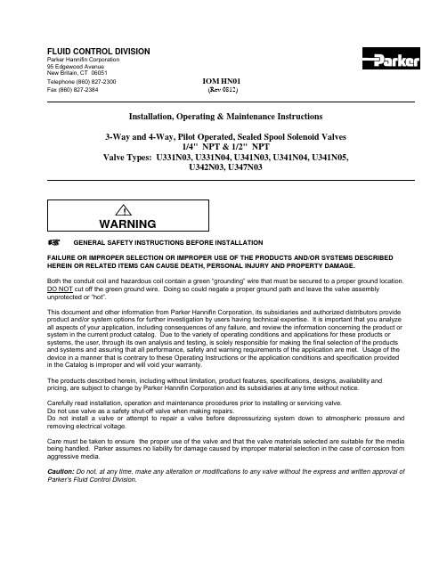
FLUID CONTROL DIVISIONParker Hannifin Corporation95 Edgewood AvenueNew Britain, CT 06051Telephone (860) 827-2300IOM HN01Fax (860) 827-2384(Rev 0812)Installation, Operating & Maintenance Instructions3-Way and 4-Way, Pilot Operated, Sealed Spool Solenoid Valves1/4" NPT & 1/2" NPTValve Types: U331N03, U331N04, U341N03, U341N04, U341N05,U342N03, U347N03GENERAL SAFETY INSTRUCTIONS BEFORE INSTALLATIONFAILURE OR IMPROPER SELECTION OR IMPROPER USE OF THE PRODUCTS AND/OR SYSTEMS DESCRIBED HEREIN OR RELATED ITEMS CAN CAUSE DEATH, PERSONAL INJURY AND PROPERTY DAMAGE.Both the conduit coil and hazardous coil contain a green “grounding” wire that must be secured to a proper ground location. DO NOT cut off the green ground wire. Doing so could negate a proper ground path and leave the valve assembly unprotected or “hot”.This document and other information from Parker Hannifin Corporation, its subsidiaries and authorized distributors provide product and/or system options for further investigation by users having technical expertise. It is important that you analyze all aspects of your application, including consequences of any failure, and review the information concerning the product or system in the current product catalog. Due to the variety of operating conditions and applications for these products or systems, the user, through its own analysis and testing, is solely responsible for making the final selection of the products and systems and assuring that all performance, safety and warning requirements of the application are met. Usage of the device in a manner that is contrary to these Operating Instructions or the application conditions and specification providedin the Catalog is improper and will void your warranty.The products described herein, including without limitation, product features, specifications, designs, availability and pricing, are subject to change by Parker Hannifin Corporation and its subsidiaries at any time without notice.Carefully read installation, operation and maintenance procedures prior to installing or servicing valve.Do not use valve as a safety shut-off valve when making repairs.Do not install a valve or attempt to repair a valve before depressurizing system down to atmospheric pressure and removing electrical voltage.Care must be taken to ensure the proper use of the valve and that the valve materials selected are suitable for the media being handled. Parker assumes no liability for damage caused by improper material selection in the case of corrosion from aggressive media.Caution: Do not, at any time, make any alteration or modifications to any valve without the express and written approval of Parker’s Fluid Control Division.DescriptionThese valves are pilot operated 2-position, 4 ported 3-way or 5 ported 4-way, and 3-position 5 ported 4-way, directional control, solenoid models. They are offered in anodized aluminum body construction. Valves may be ordered with either DIN or Conduit NEMA 2, 4, 4X integrated coils for ordinary locations or NEMA 7 and 9 for hazardous locations:Applicable StandardsFM CSADivisions I; Class I, Groups A, B, C, D Divisions I; Class I, Groups A, B, C, DDivisions II; Class I, Groups E, F, and G Divisions II; Class I, Groups E, F, and GClass 1, Zone 1, AEx m II T4 Class 1, Zone 1, Ex m II T4The spool valves comprise a standard locking manual override providing operation without electrical supply.The spool valves are offered with the following standard features:-In line pilot for a low profile-22mm DIN pilot for direct mounting in non-explosive environments.-Both Conduit and Hazardous pilots for NEMA rated and explosive environments. Mounting plate required for NEMA rated coils.-High Nominal Flow-Cv 1.2 for 1/4” valves or 1250Nl/mn-Cv 3.0 for 1/2” valves or 3000Nl/mn-Standard Fluid temperature 14°F (-10°C) to 122°F (50°C)-Single Solenoid electrically operated, combined spring & pneumatic return (U331 & U341 series)-Dual Solenoid (Bistable) electrically operated, with neutral position return closed (U342 series)-Dual Solenoid (Bistable) electrically operated, air-solenoid return (U347 series)Principles of Operation – Connection of the NAMUR spool valve3-Way ValvesThe valve is piped to a single acting spring return cylinder as follows: Supply air pressure is applied at the inlet port 1. When de-energized, the valve inlet port 1 is closed and valve cylinder port 2 is open to the valve exhaust port 3. The cylinder is in the retracted state.When the coil is energized, pressure is applied from the valve inlet port 1 to the valve cylinder port 2 forcing the cylinder open and exhausting air behind the piston to the valve exhaust port 3. The cylinder is in the extended state.4-Way ValvesThe valve is piped to a double acting cylinder as follows: Supply air pressure is applied at the valve inlet port 1. Valve port 2 is open to one port of the cylinder while valve port 4 is open to the other port of the cylinder. The solenoid valve functions in such a way that pressure is applied to either side of the piston in the cylinder, and exhausted out of the opposite side of the pressurized cylinder.When de-energized, the supply air pressure port 1 is open to the valve port 2, valve port 4 is open to valve exhaust port 5, and valve exhaust port 3 is isolated by seals on the spool. The pilot valve orifice is sealed by the insert in the plunger. The pilot valve exhaust port is open to the valve piston assembly and atmosphere.When energized, the valve inlet port 1 is open to port 4, as well as between valve port 2 and valve exhaust port 3. The spool and seals seal valve exhaust port 5. This allows pressure to be applied to other side of the piston in the cylinder, causing the piston to move, and exhaust the fluid on the other side of the piston of the cylinder into port 2, through the valve and out of valve exhaust port 3.Manual OverridesManual override - The unit is shipped with a latching manual override. For a latching override, apply force to the slotted screw component, turn clockwise to lock. To unlock, turn counterclockwise.Fluid CodesListed below are the common fluid codes The codes for the approved fluids for use with each valve are printed on the outside of the individual packaging.CODE FLUIDA- Air or non-toxic, nonflammable gasesFor the maximum fluid temperatures, as well as valve ambient temperature limitations, check the valve part number on the nameplate and refer to the catalog.Installation InstructionsPrior to installing the solenoid valve, depressurize the pipes and clean them internally to avoid particles entering theMounting position and pressure limits:Valve with DIN Coil:Mount the valve directly on the actuator with the (2) M5 thread screws provided for the 1/4" valve and with the (2) M6 thread screws for the 1/2" valve. Torque to 35 to 45 in-lbs (4 to 5 Nm). Make sure the O-rings and locating pin are assembled to the bottom of the valve prior to mounting the valve for correct positioning on the actuator. Do not use the sleeve or enclosure as a lever when applying torque.Valve with Conduit or Hazardous Coil: (see next paragraph for valve model U341N05 only)The conduit and hazardous coils require the use of a mounting plate kit due to the increased coil width. The mounting plate kit consists of the aluminum mounting/spacer plate, 2 O-rings and 2 longer screws. The valve model number U341N05 containing the 3/2, 5/2 conversion plate does not require a separate mounting kit (see next paragraph). Make sure the O-rings are assembled to the bottom of the valve before positioning the valve over the mounting/spacer plate. Make sure that the O-rings and the locating pin are assembled to the bottom of the mounting/spacer plate prior to mounting the valve onto the actuator. Use the 2 longer screws to mount the valve to the actuator. Torque to 35 to 45 in-lbs (4 to 5 Nm). Do not use the sleeve or enclosure as a lever when applying torque.Valve model U341N05 with conversion plate:With the U341N05 valve, the 3/2, 5/2 conversion plate also functions as the mounting/spacer plate for the conduit and hazardous coils. Make sure that the gasket surface with the function indicator tab is assembled toward the bottom of the valve body. The indicator tab will point toward the schematic on the top of the valve body indicating the valve function. To change the valve function, rotate the conversion plate 180 degrees keeping the gasket face toward the vale body. The O-rings and the locating pin are assembled to the bottom of the conversion plate prior to mounting the valve onto the actuator. Use the 2 of the included screws to mount the valve to the actuator. Torque to 35 to 45 in-lbs (4 to 5 Nm). Do not use the sleeve or enclosure as a lever when applying torque.The valves are multi-poised and will perform properly when mounted in any position. However, for optimum life and performance, the valves should be mounted with the spool in the vertical position to minimize wear and reduce the possibility of foreign matter accumulating inside the sleeve and spool area.Line pressure must conform to nameplate rating.Valve Piping: Correctly support and align pipes to prevent mechanical strain on the valve. Connect line pressure to the inlet port. Use of tape sealant, thread compound or sealants is permissible, but should be applied sparingly to male pipe threads only. To avoid damage to the equipment, DO NOT OVERTIGHTEN pipe connections.Media filtration: Normally, filtration is not required, but dirt or foreign material in the media may cause excessive leakage, wear, or in exceptional cases, malfunction. The valves do include a 40 micron internal pilot filter to help prevent clogging of the pilot orifice. If additional filtration is used, install the filter on the inlet side as close to the valve as possible. Clean periodically depending on service conditions.Lubrication: Lubrication is not required.ELECTRICAL CONNECTIONSGeneral Recommendations and Safety Precautions- Electrical connection must be made by qualified personnel using standard electrical practices in compliance with local authorities and the National Electrical Code.- Depending on the voltage, electrical components must be grounded according to local standards and regulations- Most valves are designed for continuous duty. To prevent the risk of personal injury, do not touch the solenoid operator which can become hot under normal operating conditions.-The solenoid coil must be assembled to the valve sleeve operator for proper valve operation. Failure to assemble the coil to the valve before applying system voltage will permanently damage the coil within a short period of time.- Electrical supply must conform to nameplate rating.Hazardous Location Coil WARNING: Valves to be installed in Hazardous Locations, must be outfitted with Hazardous Location coils only. Verify nameplate data and coil part number before installing the valve.A surge protector corresponding to the coil’s rated current or a motor safety switch with instantenous short circuit or thermal cutout (set at rated current) has to be pre-connected for each solenoid coil as a short circuit cutout. The surge protector may be positioned in the respective power supply unit or it must be pre-connected separately.W ARNING:Turn off electrical power before connecting the valve to the power source.If the coil assembly is located in an inconvenient orientation, it may be reoriented to facilitate installation. Loosen coil assembly nut, rotate coil assembly in 45° increments to desired position, and then retighten the nut with an input torque of 4.0 to 5.0 in-lbs. [0,5 Nm].DIN Coil (ND1x) and various cable option terminations: Electrical connection is made with detachable DIN 43650 B plug connector for cable dia. 6-8mm (Pg9), rotatable by 180° increments (3 pins: 2 + earth ground pin). Loosen cable screw and remove plastic housing from DIN coil. Do not remove the gasket from the DIN spades on the coil. Separate the plastic block from the housing with a small screwdriver to expose the elecctrical terminations. Feed the lead wires through the conduit hub and attach them to the appropriate screw terminal. For electrical connection within the terminal box, use field wire that is rated for 90o C or greater. Snap the plastic block back into place inside the metal enclosure. Replace the cover and hand-tighten the cover screws. Place the gasket over the DIN spades on the coil and press the terminal box and coil together. Secure the terminal box to the coil using the mounting screw provided.Slide one o-ring over and down the sleeve assembly until the o-ring rests on the valve body., Slide the DIN coil over the valve sleeve. Affix nut to sleeve and tighten between 4.0 to 5.0 in-lbs. [0,5 Nm] torque.Conduit Coil (NC1x) with 1/2” NPT connection: Conduit coils meeting NEMA 2, 4, 4X integrated coils for ordinary locations. Use suitable electrical cabling and conduit materials and components meeting applicable NEMA recommendations.Hazardous Coil (NH1x) with 1/2” NPT connection: Hazardous coils meeting NEMA 7, and 9: Divisions I and II; Class I, Groups A, B, C, and D; Class II, Groups E, F, and G. Use suitable electrical cabling and conduit materials and components meeting applicable NEMA recommendations.Coil/enclosure temperature: Standard valves are supplied with coils designed for continuous duty service. Normal free space must be provided for proper ventilation. When the coil is energized continuously for long periods of time, the coil assembly will become hot. The coil is designed to operate permanently under these conditions. Any excessive heating will be indicated by smoking and/or odor of burning coil insulation.For the maximum valve ambient conditions, as well as the fluid temperatures, check the valve part number on the nameplate and refer to the catalog to determine the maximum temperatures.MAINTENANCEPrior any maintenance work, switch off power supply, depressurise and vent the valve to prevent the risk of personal∙Preventive maintenanceValve should be exercised (cycled from de-energized to energized position several times) if stored in inventory or if inactive for a lengthy period of time (more than a month).Avoid obstruction of exhaust port when it is not connected or protect it with a cap.∙CleaningMaintenance of the valve depends on the operating conditions. They must be cleaned at regular intervals. Cleaning must be done when a slowing down of the cycle, a leakage or an abnormal noise is noticed. The components must be checked for excessive wear.Note: Depending on service conditions, filtration, and lubrication, it may be required to periodically clean and/or replace worn components.C AUTION:Do not expose plastic or elastomeric materials to any type of commercial cleaning fluid. Parts should be cleaned with a mild soap and water solution.Monostable in line Miniature pilot Bistable Miniature pilot O-ring 10O-ring 9Screws 8Under Seat Flow Path 7Pin6“Bug”cap 5Operator Sleeve 4Manual Override 3O-ring11Pilot Top Plate 2Pilot Body 1DescriptionItemPilot ValveCross Section ViewConversion PlateHazardous or Conduit Coil U331N03, U331N04 13551331524 3154 2Trouble ShootingSymptom Procedure 1. Valve fails to operate or is sluggish. 1. Check electrical supply with voltmeter. Voltage must agreewith coil rating.2. Check coil with ohmmeter for shorted or open coil.3. Make sure that pressure complies with pressure ratingmarked on valve. Pressure must not be less than minimumoperating pressure.4. Inspect for contamination in ports. Remove debris if found.Check filter in main body, clean or replace if necessary.5. Verify that the sleeve assembly and plunger spring are notdamaged.* Remove the 4 screws and gently lift off the pilot sectionof the valve. Take care not to lose the o-rings andinternal components.* Remove the top plate. Lift out and inspect the sleeve,plunger, rubber disk and spring for debris or damage.Replace sleeve assembly, top plate and 4 screws.* Make sure the manual override stem is located on theported side of the valve body.2. External leakage at sleeve flange to body joint or pilot section to main body joint. 1. Check the 4 screws are tight but do not apply excessive forceto damage the plastic plate.2. If leakage persists, remove sleeve and check flange ando-ring seals for damage. Refer to step 5 above for disassembly.。
派克各式电磁阀及原理介绍

派克各式电磁阀及原理介绍派克各式电磁阀及原理介绍上海维特锐专业从事各种国外工控自动化产品的进口贸易。
主要经营品牌如下:德国品牌:KRACHT 克拉克、VSE 威士、HYDAC贺德克、BUCHER布赫、P+F 倍加福FESTO 费斯托、IFM 易福门、SIEMENS 西门子、SICK 施克、TURCK图尔克、E+H 恩德斯豪斯、 LEUZE 劳易测、巴士德Barksdale、德国PLATING ELECTRONIC、 KOBOLD 科宝、巴鲁夫BALLUFF、海隆HERION 、HEIDENHAIN海德汉、HAWE哈威美国品牌:PARKER 派克、ASCO 阿斯卡、美国 ACE、VICKERS 威格士、MAC、葆德BALDOR、MOOG穆格、NUMATICS 纽曼帝克、JOUCOMATIC 捷高意大利品牌:ATOS 阿托斯、VESTA维斯塔、CAMOZZI 康茂盛、迪普马duplomatic 英国品牌:牛顿NEWTONS4TH日本品牌:SMC、CKD 喜开理、油研 YUKEN、NACHI 不二越TAIYO 太阳铁工、SUNX 神视、DAIKIN 大金液压KEYENCE 基恩士、OMRON 欧姆龙、KOGANEI 小金井派克各式电磁阀及原理介绍派克电磁阀是由电磁线圈和磁芯组成,是一个含有一个或几个孔的阀门。
当线圈通电或断开时,磁芯的操作将导致流体通过阀体或被切断,以便改变流体的方向。
电磁阀的电磁部件由固定铁芯、移动铁芯、线圈等组成。
阀体由滑动阀芯、滑动阀套、弹簧座等组成。
电磁线圈直接安装在阀体上,阀体密封在密封管中。
形成一个简单而紧凑的组合。
我们生产中常用的电磁阀有二位三环、二位四环、二位五环等。
这里我们首先谈一下二的含义:对于电磁阀是带电的和功率损失的,对于阀门的控制是开闭的。
它由阀体、阀盖、电磁元件、弹簧和密封结构等组成。
动铁芯底部的密封块借助弹簧压力关闭阀体进气口。
通电后,电磁铁被吸入,动铁芯上部的弹簧密封块封闭出风口,气流从进气口进入膜头,起到控制作用。
中冶宝钢技术服务有限公司渣包车技术方案及对比

中冶宝钢技术服务X X X重型机械分公司渣包车项目技术方案及对比目录投入使用渣包车(国产)技术方案 (3)一、70t平台式渣包车(铰接式驾驶室侧置) (3)1、技术特点 (3)2、整车性能参数 (4)3、主要配套件 (5)二、65t铰接式U型渣包车(推荐) (9)1、技术特点: (9)2、设备性能技术参数 (10)3、主要配套件 (12)设备设计、制造标准 (14)渣包车对比 (15)一、国外渣包车对比 (15)二、国内渣包车对比 (16)三、综合对比(中冶重机渣包车与国外渣包车对比) (17)附:中冶宝钢技术服务XXX渣包车业绩表BGC-35、BGC-35铰接式、BCG-60、BGC-80基本参数特种设备型式试验报告投入使用渣包车(国产)技术方案一、70t平台式渣包车(铰接式驾驶室侧置)1、技术特点抱罐车是冶金企业渣处理工艺中的关键运输设备,能够实现从地坪或者U型平板车上自装卸渣罐,具有自装卸、倾倒、运输等功能。
1.1主要技术特点:模块化设计思想:整车分为动力单元、操纵单元和工作平台三大模块,其中仅工作平台为非标设计。
整车可靠性高,通用性好。
1.2转弯半径更小整车采用铰接式布置,设计最大转向角度±70°,最小转弯半径约为8500mm。
1.3先进可靠的液力机械传动元器件选用美国DANA公司标准产品,起动扭矩大、换档平稳无冲击,全自动电控换档,操作简单舒适,性能可靠。
1.4重心更低、载荷更大后桥采用非标设计的90吨级一线两轴承重桥,配16个实心轮胎,实现大吨位承载,接地比压低,轮轴重量小,对路面要求相对较低。
1.5车架、工作机构的优化设计车架采用三维软件设计,关键部件通过有限元软件进行强度分析。
车架主体材料采用优质Q345B板材。
采用混合气体保护焊接,主梁受拉区的翼缘板、腹板的对接焊缝进行无损探伤,超声波探伤按GB/T11345-1989 中规定应不低于Ⅱ级。
车架焊接完后震动消除焊接应力。
KRESS渣包车主控电脑功能浅谈

KRESS渣包车主控电脑功能浅谈摘要:该文以P-160CSE型渣包车车载主控电脑为重点,主要介绍了该类车载主控电脑的信息功能、基本数据变更、整车数据监测和控制数据调整等四个主要功能,并从整车、主要总成、关键部件角度和使用、维修方面进行了归纳和总结。
对正确运用该类车辆的车载主控电脑具有指导和借鉴意义。
关键词:P-160CSE型渣包车;主控电脑;主要功能美国KRESS公司生产的P-160CSE型渣包车是一款集机械安装、电气控制、液压传动于一体的高技术密集型产品,在有色行业的主要冶炼企业得到一定的应用,其主控电脑(IQAN)功能控制技术属世界领先水平,软件为美国PARKER 公司所研发。
正确运用主控电脑和使用关键主控程序可以高效、精准、快速地判断车辆运用水平和技术状况,为保持和恢复车况提供技术服务指导。
为更好地充分应用其主要功能,现将主要控制功能项目归纳和总结如下:1 信息功能(INFORMATION)信息功能单元可以提供、记录、统计设备的原始配置状况、运转状况记录、设备报警记录、故障分类清单等。
1.1 原始配置状况(1 )整机型号、服务代码、生产月份、上船日期等。
(2)发动机、变速器、变矩器、主控多路阀、主控仪表等总成件的型号、规格、序列号、服务代码。
(3)整车主控软件、发动机管理软件、变速器控制软件等的文件号、厂家信息、版本序列号、版权期限等。
(4)主控软件(990315M)与主要总成件软件即发动机管理软件(CAT.ECM)、变速器控制软件(CAT.TRS.ECM)间通讯接口及访问信息要求等。
1.2 运转状况记录(1)整车启动、停止时刻记录。
(2)起重运输渣包重量及包号记录。
1.3 设备报警记录(1)输出电流超标报警主要指超过或不足比例电磁阀、普通电磁阀正常工作所需电流的报警记录。
常标记为Saturated、Open Load。
(2)输入电压超标报警主要指各传感器所反馈或产生的电压信号过高、过低的报警记录。
国内排污泵业前十品牌总榜排污泵型号
1.上海阳光泵业制造有限公司上海阳光泵业是集设计/生产/销售泵、给水设备及泵用控制设备于一体的大型综合性泵业集团,是中国泵行业的龙头企业。
总资产达38亿元,在上海、浙江、河北、辽宁、安徽等省市拥有7家企业,5个工业园区,占地面积67万平方米,建筑面积35万平方米。
上海阳光获得了“上海市质量金奖”、“上海市科技百强企业”、“上海市名牌产品”、“中国质量信用AAA级”、“全国合同信用等级AAA 级”、“质量、信誉、服务三优企业”、“中国最具竞争力的商品商标”、“五星级服务认证”等荣誉,连续多年入选全国机械500强。
高端人才和高素质的员工队伍是阳光发展的动力。
集团现有员工4500余人,其中工程技术人员500多名,主要由国内知名水泵专家教授、博士硕士、中高级工程师、高级工艺师组成,形成了具有创新思维的梯队型人才结构。
科技创新,是阳光基业长青的生命之源。
集团是上海市高新技术企业、上海市知识产权示范企业和上海市专利示范企业。
上海市级的“企业技术中心”,每年以销售总额的5%,用于技术创新和新产品研发。
2.深圳市稳超科技有限公司稳超科技有限公司是英格索兰系列螺杆式空气压缩机及零配件的深圳直属代理商。
主要从事空压机整套系统设备销售和维修保养服务及管路工程、余热回收等服务。
可帮您设计空压站系统、厂房管道安装、气源质量改善及专业技术指导等。
公司成立至今凭借雄厚的专业知识、完善的售后服务及货真价实的宗旨,制订以您的利益为主导而深受客户支持,并不断得到客户认可及推广。
为了能更好的为客户服务,公司都有五个部门即:管理部、业务部、行政部、服务部和工程部,为客户提供购机、工程施工和售后服务一体式服务,全力打造“提供工业压缩空气的动力专家”形象。
3.德能泵业(天津)有限公司德能泵业,全名称:德能泵业(天津)有限公司是一家集生产制造、技术研发、项目设计为一体的大型泵类企业,位于环渤海天津小站工业区——紧邻滨海新区天津港港口,四面高速环绕,是京津冀一体化工业群重要位置之一。
Parker插装阀样本-逻辑阀LEsection
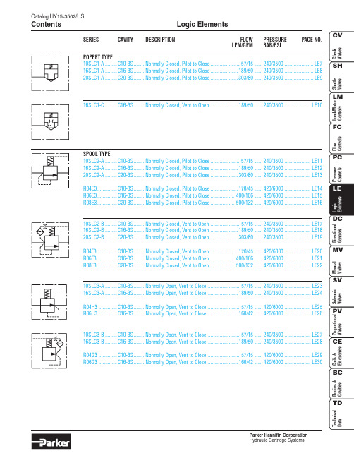
Catalog HY15-3502/USLogic Elements ContentsParker Hannifin CorporationSERIES CAVITY DESCRIPTION FLOW PRESSURE PAGE NO.LPM/GPM BAR/PSIPOPPET TYPE10SLC1-A.........C10-3S........Normally Closed, Pilot to Close.......................57/15......240/3500......................LE7 16SLC1-A.........C16-3S........Normally Closed, Pilot to Close.....................189/50......240/3500......................LE8 20SLC1-A.........C20-3S........Normally Closed, Pilot to Close.....................303/80......240/3500......................LE916SLC1-C.........C16-3S........Normally Closed, Vent to Open.....................189/50......240/3500....................LE10SPOOL TYPE10SLC2-A.........C10-3S........Normally Closed, Pilot to Close.......................57/15......240/3500....................LE11 16SLC2-A.........C16-3S........Normally Closed, Pilot to Close.....................189/50......240/3500....................LE12 20SLC2-A.........C20-3S........Normally Closed, Pilot to Close.....................303/80......240/3500....................LE13R04E3...............C10-3S........Normally Closed, Pilot to Close.....................170/45......420/6000....................LE14 R06E3...............C16-3S........Normally Closed, Pilot to Close..................400/106......420/6000....................LE15 R08E3...............C20-3S........Normally Closed, Pilot to Close..................500/132......420/6000....................LE1610SLC2-B.........C10-3S........Normally Closed, Vent to Open.......................57/15......240/3500....................LE17 16SLC2-B.........C16-3S........Normally Closed, Vent to Open.....................189/50......240/3500....................LE18 20SLC2-B.........C20-3S........Normally Closed, Vent to Open.....................303/80......240/3500....................LE19R04F3...............C10-3S........Normally Closed, Vent to Open.....................170/45......420/6000....................LE20 R06F3...............C16-3S........Normally Closed, Vent to Open..................400/106......420/6000....................LE21 R08F3...............C20-3S........Normally Closed, Vent to Open..................500/132......420/6000....................LE2210SLC3-A.........C10-3S........Normally Open, Vent to Close.........................57/15......240/3500....................LE23 16SLC3-A.........C16-3S........Normally Open, Vent to Close.......................189/50......240/3500....................LE24R04H3..............C10-3S........Normally Open, Vent to Close.........................57/15......420/6000....................LE25 R06H3..............C16-3S........Normally Open, Vent to Close.......................160/42......420/6000....................LE2610SLC3-B.........C10-3S........Normally Open, Vent to Close.........................57/15......240/3500....................LE27 16SLC3-B.........C16-3S........Normally Open, Vent to Close.......................189/50......240/3500....................LE28R04G3..............C10-3S........Normally Open, Vent to Close.........................57/15......420/6000....................LE29 R06G3..............C16-3S........Normally Open, Vent to Close.......................160/42......420/6000....................LE30LE1Logic ElementsCatalog HY15-3502/USTechnical TipsParker Hannifin CorporationCatalog HY15-3502/USLogic Elements Technical TipsParker Hannifin CorporationLE2LE3Logic ElementsCatalog HY15-3502/USTechnical TipsParker Hannifin CorporationCatalog HY15-3502/USLogic Elements Technical TipsParker Hannifin CorporationLE4LE5Logic ElementsCatalog HY15-3502/USTechnical TipsParker Hannifin CorporationDIRECTIONAL CONTROL EXAMPLESTHREE-WAY BRIDGE CIRCUITS Circuit 1, with **SLC1A poppet logic element.Circuit 2, with **SLC2A/R0*E3spool logic element.Circuit 3, with **SLC2A/R0*E3spool logic element.NOTE: Pilot pressure must exceed load pressure in order for valve to close.FOUR-WAY BRIDGE CIRCUITSCircuit 1, with **SLC1A poppet logic elements.Circuit 2, with **SLC2A/R0*E3 spool logic elements.Required Flow PathPilot Pressure Applied To PA PB 123Available From CircuitNONOXXYESNO X X XRequired Flow PathPilot Pressure Applied To PA PB 123Available From CircuitNOYESXXNO YES X XPilot Pressure Applied To P1P2P3P4P5Required Flow PathPilot Pressure Applied To P1P2P3P4P5Required Flow PathPilot Pressure Applied To P1P2P3P4P5Required Flow PathYES YES YES YES YESNO NO NO NO NOYES YESNO NO NONONO YES YES NOYES YES YES YESNOYESNONOYES YESNO YES YES NO YESYES YES NO YES YESNO YES YES YES YESNO YES NO YES YESYESNOYESNOYESYES YES YES NO YESYES NO YES YES YESP APBBACBAP APB CPB BP A ACABC ABCABC ABCPP5TP1P2A P3BP4P2A P1PP5TP4BP3ABP T ABPTABP T ABPTABP T ABP T ABP T ABP T ABP T ABPTABP T ABP T ABP T NOTE: Pilot pressure must exceed load pressure in order for valve to close.Catalog HY15-3502/USLogic Elements Technical TipsParker Hannifin CorporationLE6LE7Catalog HY15-3502/USPoppet Type Logic Valve Series 10SLC1-AParker Hannifin CorporationTechnical Information(3)Poppet Type Logic ValveSeries 16SLC1-A Catalog HY15-3502/USParker Hannifin CorporationTechnical Information(3)(2)LE8LE9Catalog HY15-3502/USPoppet Type Logic Valve Series 20SLC1-AParker Hannifin CorporationTechnical Information(1)(3)(2)Poppet Type Logic ValveSeries 16SLC1-C Catalog HY15-3502/USParker Hannifin CorporationTechnical Information(3)(2)LE10LE11Catalog HY15-3502/USSpool Type Logic Valve Series 10SLC2-AParker Hannifin CorporationTechnical InformationSpool Type Logic ValveSeries 16SLC2-A Catalog HY15-3502/USParker Hannifin CorporationTechnical Information(1)(3) (2)LE12LE13Catalog HY15-3502/USSpool Type Logic Valve Series 20SLC2-AParker Hannifin CorporationTechnical InformationSpool Type Logic ValveSeries R04E3Catalog HY15-3502/USParker Hannifin CorporationTechnical InformationLE14LE15Catalog HY15-3502/USSpool Type Logic Valve Series R06E3Parker Hannifin CorporationTechnical InformationSpool Type Logic ValveSeries R08E3Catalog HY15-3502/USParker Hannifin CorporationTechnical InformationLE16LE17Catalog HY15-3502/USSpool Type Logic Valve Series 10SLC2-BParker Hannifin CorporationTechnical Information(1)(3) (2)LE18Parker Hannifin CorporationLE19Parker Hannifin CorporationSeries R04F3Parker Hannifin CorporationTechnical InformationLE20LE21Parker Hannifin CorporationSeries R08F3Parker Hannifin CorporationTechnical InformationLE22LE23Parker Hannifin CorporationSeries 16SLC3-AParker Hannifin CorporationTechnical Information(2)(3) (1)LE24LE25Parker Hannifin CorporationSeries R06H3Parker Hannifin CorporationTechnical InformationLE26LE27Parker Hannifin CorporationLE28Series 16SLC3-BParker Hannifin CorporationTechnical Information (2)(3)(1)LE29Parker Hannifin CorporationLE30Spool Type Logic Valve Series R06G3Catalog HY15-3502/USParker Hannifin CorporationHydraulic Cartridge SystemsTechnical Information。
十大螺纹插装阀比较
【十大螺纹插装阀】主流生产厂家比较螺纹插装阀是有一定的插孔标准的.这个插孔标准为ISO7789与SAE的标准.但自1980年代以后.SUN公司放弃SAE标准,自己创立了新的SUN的标准后,目前市场的主流就有三种规格.目前最大个规格标准还是SAE,基本上HF,CCC,INTEGRATED等美系品牌多是采用SAE标准.由于基础设计的局限性,导致ISO的应用变成比较势力单薄.而SUN标准的插孔因为采用中置螺纹及公制M螺牙,使得通流量的设计更为大,设计师在应用斜孔设计时变更为弹性,逐渐的成为众家新产品设计时的标准.1.HYDRAFORCE(海德福斯)1983年,当时世界上规模最大的螺纹插装阀专业生产厂Modular公司被Vickers公司并购。
两年后,3个当年Modular的员工建立了HYDRAFORCE公司。
至今,HF在美国的厂房达13,000m²,在英国的厂房也有4,650m²。
2003年销售额已达90MUS$,螺纹插装阀的生产规模是世界第一。
以前产品基本以中压为主,无平衡阀。
现在也已开发了很多高压的阀。
孔型以ICC 系列为主。
2.SUNSUN公司建立于1970年。
目前在美、英、德、法、韩、印多处有子公司。
1998年与台湾橡达公司合作,在上海松江建立了一个合资子公司。
2011年初退出了合资,建立了自己在中国的销售公司。
橡达公司仍然是SUN产品的代理商。
2004年螺纹插装阀的产能就达到5.8 万件/周。
2010年销售额达到了150MUS$,税后纯利润达12%。
公司销售收入约75%来自螺纹插装阀,25%则来自阀块和集成块。
产品约70%供应移动液压,30%固定液压。
孔型自成一格,公制英制螺纹兼有。
3.Sterling(斯特林)母公司在英国的Crewkerne。
以前生产汽车零件,60年代后期开始生产螺纹插装阀。
90年代初,美国Waterman公司的主任设计师Kolchinski先生到了Sterling公司美国分部,开始研发电磁阀。
进口配件大全
VARCO顶驱配件导轨安全销(PIN,LYNCH)
UNIVERBE30200U,AC110V
ATOS双联泵 PFEX2-32022/31016/3DT
科隆物位计BM70A/HA/RL/D6/N0/LP/T9/DC/P1/V1/N1/E0/FP
哈里伯顿100003472
德瑞克电机SGX55-15-380/400-5-001
ORGA灯泡34T12075
派克液压马达F12-030-MF-IH-K-000-000-0
猫牌CAT高压泵6761
CAT高压水泵435
猫牌高压水泵2510
猫牌高压柱塞泵2530
CAT高压柱塞泵2531
CAT柱塞泵2537
库美KOOMEY631-5354
库美KOOMEY080-7231
库美KOOMEY631-5359
卡特皮带6N6654
KOOMEY库美液压安全阀15-50011
KOOMEY库美气囊组1000-9463
KOOMEY库美调节阀10-00253
KOOMEY库美调节箱3003-1128
KOOMEY库美调节箱压盖301076
贺德克过滤器RF3-4-EPT2-NM-N-1-1-0/KS100-4
HYDAC过滤器RF3-4-EPT2-NM-N-1-1-0/KS100-4
Anritsu限幅器1K50A
英格索兰气动马达M007RVR021AR4
ORGA雾笛导航控制盘控制板CODER-MK2(194A雾笛)
TEMA天马接头TIF3821
MISSION米森离心泵6*5*14
MISSION米森离心泵8*6*11
关键基础件——机械工业“由大变强”的关键

关键基础件——机械工业“由大变强”的关键中国机械工业联合会机经网工作部王华君经过多年的努力,2009年我国机械工业总产值已经突破10万亿元,对全国工业总产值、新产品产值、利润和税金增长的贡献率均居工业各行业第一位,行业整体规模在世界上已经数一数二。
但是,我国机械工业“大而不强”的现状仍未得到根本改观。
关键基础件发展滞后,核心零部件受制于人,已成为制约我国机械工业实现“由大变强”的关键所在。
什么是关键基础件?所谓关键基础件,主要指的是为重大技术装备配套的高档轴承、齿轮、液压件、气动元件、密封件、紧固件等六大类关键机械基础件。
机械基础件是整个机械工业的基础,在机械工业中占据重要地位,而关键基础件则是机械基础件中最为关键核心的部分。
世界机械强国建立在强大的关键基础件产业之上基于关键基础件在机械工业中的重要地位,世界机械强国如美国、德国、日本等都十分重视关键基础件的发展,建立了强大的关键基础件工业。
美国在国防军工、航空航天、汽车、工程机械、风电设备、农业机械、数控机床等装备制造领域处于全球领先地位,拥有强大的关键基础件产业。
例如,铁姆肯(Timken)集团是世界领先的轴承和动力传动产品供应商;伊顿(Eaton)公司在许多工业领域都是全球领导者,是世界液压气动行业广为认同的领先者;莱克斯诺(Rexnord)工业集团是全球领先的复杂工艺机械传动部件制造商;派克(Parker)公司则是世界一流的流体传动制造商,在液压气动机械领域享有国际顶级声誉。
德国作为老牌机械强国,在轴承制造、齿轮传动和驱动部件制造、液压和气压动力机械及元件制造等关键基础件领域处于世界领先水平。
例如,舍弗勒(Schaeffler)集团是全球范围内生产滚动轴承和直线运动产品的领导企业;采埃孚(ZF)集团是世界齿轮、传动和驱动部件制造行业的领军企业;SEW集团在齿轮传动和减速器领域居世界领先地位;博世力士乐(Bosch Rexroth)是全球领先的传动与控制技术专家,在液压气动等传动控制领域居世界前列。