SMC-真空系统
SMC气动第三册(真空元件)
记号 06 08 10 12 01 02 03
尺寸 ø6 ø8 ø10 ø12 Rc 1 8 Rc 1 4 Rc 3 8
形式 快换接头 快换接头 快换接头 快换接头 螺纹拧入 螺纹拧入 螺纹拧入
表① 连接形式的组合
主体形式 盒型 (内置消声器) 直接配管型 (无消声器) ① ② ③ ① ② ③ SUP 快换接头 快换接头 螺纹拧入 快换接头 快换接头 螺纹拧入 VAC 快换接头 螺纹拧入 螺纹拧入 快换接头 螺纹拧入 螺纹拧入 EXH — — — 快换接头 快换接头 螺纹拧入
页号
5.01 5.03 5.04 5.06 5.07 5.09 5.11 5.15 5.22 5.23 5.34 5.36 5.37 5.38 5.39 5.42 5.44 5.46 5.47 5.48 5.51 5.53 5.54 5.57 5.59 5.60 5.61 5.63 5.64 5.65 5.68 5.70 5.72 5.73 5.74
注意
1 配管不能是螺旋状。
真空侧和供给侧都不能出现螺旋状配管, 应尽量短而直。 配管容积增 大则响应时间变长。
2 真空发生器排气侧的配管有效截面积应大。
排气一旦节流,真空发生器的性能就变差。
4 吸入流量过大,则真空开关的设定困难。
几 mm大小的小工件, 一旦选定吸入流量过大的真空发生器, 和未吸 着时的真空压力之差太小, 会使真空压力开关的设定变困难, 故要选 定合适的真空发生器。
注意
1 方向控制阀,速度控制阀等相关元件应参见各自样本的注意 事项。
维护
警告
1 要定期对真空过滤器和消声器进行清洗。
过滤器及消声器的孔眼被堵, 真空发生器的性能便降低。 在粉尘多的 场合,应使用处理流量大的真空过滤器。
SMC 真空系统ppt课件
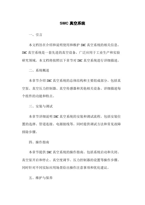
压
力
Pvx63%
P
T1
2T1
3T1
T1 达到时间(sec) T2
Pv:最终真空压力
T1:到达最终真空压力Pv的63%的时间 3T1:到达最终真空压力Pv的95%的时间
41
SMCGZ Pneumatics Ltd.
真空系统
真空系统案例选型
INTERNATIONAL TRAINING
3.计算真空发生器最大吸入流量Qe
v d 2l
4000
d:配管的内径(mm)
L:配管的长度(m)
T:真空到达时间
40
SMCGZ Pneumatics Ltd.
真空系统
真空系统案例选型
INTERNATIONAL TRAINING
响应时间
T1
60v Q
T2 3T1
供给阀 (切换阀)
的动作
ON OFF
Pv
真 空
Pvx95%
真空系统
真空系统案例选型
INTERNATIONAL TRAINING
• 当工件吸着有泄漏时,最大吸入流量应按以下标准计算
Qm
ax
(2
~
3)Q
(2
~
3)(60v T
QL
)
QL 11.1 SL
17
SMCGZ Pneumatics Ltd.
真空系统
真空系统组成
真空压力开关
INTERNATIONAL TRAINING
确保安全吸住工件的真空压力,输出电信号给真空控制系统。
ZSP1
ZSE2
ZSE3
PSE1100
ZSE30A
18
SMC-真空止回阀原理
Symbol
A5A5 A01A01 AG1AG1
M5 x 0.8 R1/8 G1/8
— —
—
B5W4
Male thread Pad side
M5 x 0.8 Rc1/8 G1/8
— —
—
B01W6 BG1W6
Female thread Pad side
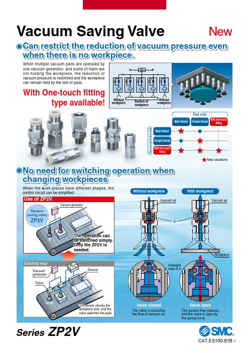
Selection Conditions
Workpiece: No leakage and several sizes Required vacuum pressure: – 50 kPa or more of vacuum pressure per vacuum pad Part number of vacuum saving valve used: ZP2V-A8-05 (Connection thread size for pad side: M8, Fixed orifice size: ø0.5)
No need for switching operation when changing workpieces
When the work pieces have different shapes, the control circuit can be simplified. Without workpiece
A5 A8 A01 AG1 AN1
— — — —
—
Male thread Pad side
03 05 07 10
0.3 0.5 0.7 1.0
Female thread/Male thread
SMC真空压力表 使用手册.pdf
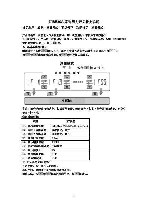
Z/ISE30A 系列压力开关设定说明设定顺序:通电—测量模式—零点校正—功能设定—测量模式产品通电后,自动进入压力测量模式,第一次使用时,请按如下顺序操作。
1、零点校正:产品第一次使用时,通电且不施加气压时,如果显示值不为零,和键同时按住1s 以上,显示值归零。
2、基本功能设定:测量模式下按住键2s 以上,压力开关进入功能设定模式,显示屏显示为。
按和键选择对应功能后按进入详细功能设置。
备注:部分功能为可选功能,根据型号而定。
特定型号下如果不包含某可选功能,对应位置显示。
全部功能列表:项目出厂设置F0:单位选择功能 ISE-Mpa,ZSE-KPa,Option P-psi F1:OUT1规格设定 迟滞模式,常开F2:OUT2规格设定 迟滞模式,常开 F3:响应时间设定 2.5 ms F4:显示精度设定 1/1000 F5:自动预设功能设定 手动模式F6:显示值校正 0% F7:省电模式选择 OFF F8:密码锁设定OFF1)F0-单位选择功能可选功能,部分型号无此功能。
单位不同,显示屏开显示的数值范围不同。
操作方法:按和键选择对应单位,按键确认。
测量模式按住键2s 以上功 能 选 择 模 式功能设定2)F1-OUT1输出规格设定方法:此部分可设置输出类别(迟滞型/比较型)和输出模式(常开/常闭)设定。
按键进入单位选择模式按和键选择对应单位交替显示按键完成设定返回到功能选择模式,屏幕显示F0F0-单位选择功能设定完成输出模式常开型 出厂时默认设置常闭型迟滞模式(出厂时默认设置) 压力输出迟滞(H-1)压力输出压力输出迟滞(H-1)压力输出比较模式(也称窗口比较模式) 迟滞模式(出厂时默认设置) 比较模式(也称窗口比较模式) 迟滞(H1) 迟滞(H1)迟滞(H1) 迟滞(H1)功能选择模式下按和至屏幕显示,然后按进入OUT1规格设定。
压力设定状态:此状态下设定压力开关输出的ON/OFF 点。
以迟滞型为例:输出方法:当压力超过设定值时,开关输出变为ON 。
SMC ZB真空发生器组件中文使用说明书
机 种 名 称小型真空单元 真空发生器/真空泵系统系 列ZB系列使用说明书目录安全注意事项 2 型号表示・型号体系 9 产品各部分名称 12 安装・设置 13 空气源 15 使用供给压力 16 配管 16 V通口Ass’y品的使用 17 关于电磁阀 21 构造图・零件构成 25 维护・保养 26 滤芯更换要领 28 吸音材更换要领 28 电磁阀(供给阀・破坏阀)更换要领 29 关于集装式产品 30 关于过滤罩 30 关于破坏流量调整针阀 31 关于真空发生器的排气 31 规格 32 回路图 35 重量 37 真空发生器的排气特性・流量特性 38 真空泵系统流量特性 39 关于流量特性表 40 关于压力传感器Ass’y品 40 关于真空用压力开关Ass’y品 41 故障一览表 42安全注意事项此处所示的注意事项是为了能安全正确的使用本产品,预先防止对您和他人造成危害或损失而定。
为了表示这些事项的危险程度,将注意事项分成「注意」「警告」和「危险」三个等级。
不论哪个等级,都是与安全相关的重要内容,除了必须遵守国际规格(ISO/IEC)、日本工业规格(JIS)※1)以及其他安全规则※2以外,这些内容也请务必遵守。
*1) ISO 4414: Pneumatic fluid power -- General rules relating to systems.ISO 4413: Hydraulic fluid power -- General rules relating to systems.IEC 60204-1: Safety of machinery --Electrical equipment of machines. (Part1: General requirements)ISO 10218-1992: Manipulating industrial robots -Safety.JIS B 8370: 空气压系统通则JIS B 8361: 油压系统通则JIS B 9960-1: 机械类的安全性-机械的电气装置((第1部:一般要求事项)JIS B 8433-1993: 键控工业机器人-安全性等*2) 劳动安全卫生法 等注意: 误使用时,有可能对人和物品造成损害。
SMC真空压力表ZSE30A-01-N设定

第4页
图一
图二
图三
图四
图五
图六
1、在当前界面按住S键3秒;进入模式选取界面F0; 2、上下切换键切换到图一F1;按S键确认进入内部设定画面; 3、图二和图三画面交替显示,在图三画面按S确认,进入内部设定画面; 4、图四和图五画面交替显示,在图五画面按S确认,进入内部设定画面; 5、在数字显示画面,按上下切换键设定报警接线值; 6、按S键3秒返回当前界面;
一、初始界面、零位校正: SMC真空压力表ZSE30A-01-N设定 显示界面
第1页
上切换键 模式切换/ 确认键
下切换键
1、在通电不施加正负气压时,同时按住上和下切换键1秒以上显 示界面数据零位校正;
二、复位恢复出厂设置: SMC真空压力表ZSE30A-01-N设定
第2页
图一
图二
图三
图四
1、在当前界面按住S键3秒;进入模式选取界面F0; 2、上下切换键切换到F99界面;按பைடு நூலகம்键确认进入内部设定画面; 3、上下切换键切换OFF和ON选取,同时按下S和下切换键5秒以上确认恢复 出厂设置; 4、按S键3秒返回当前界面;
三、单位的选取: SMC真空压力表ZSE30A-01-N设定
第3页
图一
图二
1、在当前界面按住S键3秒;进入模式选取界面F0; 2、按S键确认进入内部设定画面; 3、按上下切换键切换到图二PA画面(单位KPa),按S键确认; 4、按S键3秒返回当前界面;
四、工作时报警界限值设定: SMC真空压力表ZSE30A-01-N设定
SMC真空发生器原理图
产品名称:SMC真空发生器原理图
真空的含义是指在给定的空间内低于一个大气压力的气体状态,是一种物理现象。
在“虚空”中,声音因为没有介质而无法传递,但电磁波的传递却不受真空的影响。
事实上,在真空技术里,真空系针对大气而言,一特定空间内部之部份物质被排出,使其压力小于一个标准大气压,则我们通称此空间为真空或真空状态。
真空常用帕斯卡(Pascal)或托尔(Torr)做为压力的单位。
在自然环境里,只有外太空堪称最接近真空的空间。
1641年意大利数学家托里拆利在一根长管子内加满水银,然后很缓慢的将管口倒转在一个盛满水银的盆内,管子内水银柱的末端是76厘米高。
这时玻璃管最上方无水银地带是真空状态。
这一实验为“托里拆利实验”,完成实验的玻璃管为“托里拆利管”。
爱因斯坦在用场论观点研究引力现象时,已经认识到空无一物的真空观念是有问题的,他曾提出真空是引力场的某种特殊状态的想法。
首先给予真空崭新物理内容的是P.A.M.狄拉克。
狄拉克于1930年为了摆脱狄拉克方程负能解的困境,提出真空是充满了负能态的电子海。
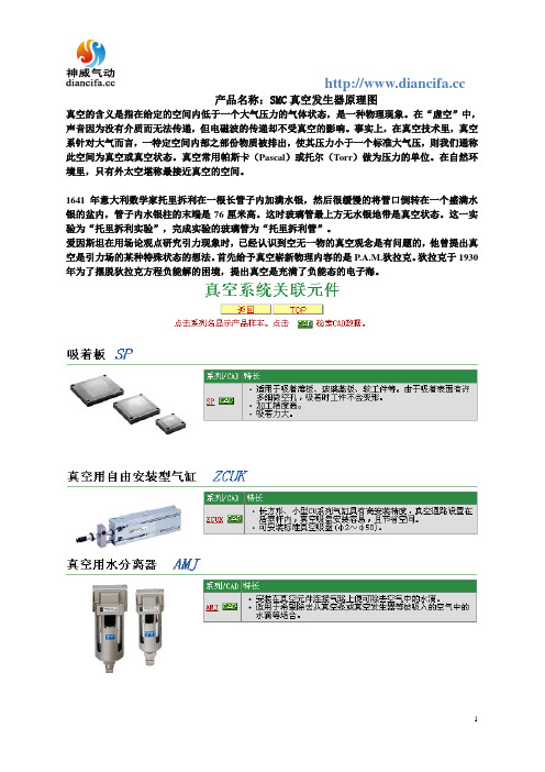
SMC真空发生器的简介和分类

SMC 真空发生器的简介和分类
SMC 真空发生器就是利用正压气源产生负压气源的一种高效、 新型、清洁、小型、经济的真空元器件,这使得在有需要压缩空气的 地方, 或者在一个气动控制系统中同时需要正负压的地方获得负压变 得相对非常容易和便捷。 SMC 真空发生器被广泛地应用在工业自动化体系中工程机械、 电子产品、包装材料、塑料、印刷以及机器人等行业和领域。SMC 真空发生器的传统用途是与吸盘紧密配合, 进行各种物料和材质的吸 附、搬运等动作,尤其适合于吸附易碎、柔软以及薄的非铁、非金属 材料或者球型物体。在这一类的工业应用中,它们的共同特点是所需 的抽气量比较小,真空度要求并不高且是间歇工作的性质。
下面是 SMC 真空发生器的具体分类:
1.ZM 系列真空发生器:
2.ZMA 系列带电子式延时器的真空发生器:
3.ZH 系列真空发生器:
4.ZU 系列直通式真空发生器:
5.ZL 系列多级真空发生器:
6.ZYY/ZYX 系列真空发生器与电磁阀组合元件:
7.ZQ 系列薄型ຫໍສະໝຸດ 空组件:其他关于 SMC 真空发生器的配合元件——SMC 真空吸盘的详细 介绍,将在以后的文章中呈上。
smc真空发生器原理

smc真空发生器原理SMC真空发生器原理。
SMC真空发生器是一种常用的真空设备,它通过特定的原理实现对空气的抽取,从而产生一定的真空度。
在工业生产和实验室研究中,真空设备的应用非常广泛,而SMC真空发生器作为其中的一种,其原理和工作机制备受关注。
首先,我们来了解一下SMC真空发生器的结构。
它通常由真空泵、气缸、电磁阀、真空表、压力开关等部件组成。
真空泵是核心部件,它通过机械、物理或化学方法将气体抽取出来,从而形成真空。
气缸和电磁阀则用于控制气体的流动和压力,真空表和压力开关则用于监测和调节真空度。
接下来,我们来介绍一下SMC真空发生器的工作原理。
当真空发生器开始工作时,真空泵会启动,开始抽取气体。
同时,电磁阀会关闭,防止外部气体进入系统。
随着真空泵的工作,气缸会逐渐形成负压,使得容器内的气体被抽取出来。
当真空度达到设定数值时,真空表会发出信号,通知压力开关停止真空泵的工作,从而保持系统的稳定状态。
在实际应用中,SMC真空发生器可以根据需要进行调节,以满足不同场合的需求。
通过调节电磁阀和真空泵的工作时间和频率,可以实现对真空度的精确控制。
这使得SMC真空发生器成为许多工业生产和实验室研究中不可或缺的设备。
总的来说,SMC真空发生器的原理和工作机制相对简单,但在实际应用中具有重要的作用。
它通过真空泵等部件的配合,实现对气体的抽取,从而产生一定的真空度。
在工业生产中,它可以用于各种真空工艺,如真空包装、真空干燥等;在实验室研究中,它可以用于真空蒸发、真空冷冻等实验。
因此,对SMC真空发生器的原理和工作机制有深入的了解,对于提高工作效率和保证实验结果的准确性具有重要意义。
SMC ZQ A系列紧凑型真空单元说明书
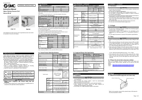
Instruction ManualSpace Saving Vacuum UnitSeries ZQ□AThe intended use of the vacuum unit is to generate vacuum and controlthe operation of suction and release.These safety instructions are intended to prevent hazardous situations and/or equipment damage. These instructions indicate the level of potential hazard with the labels of “Caution,” “Warning” or “Danger.”They are all important notes for safety and must be followed in additionto International Standards (ISO/IEC) *1), and other safety regulations.*1) ISO 4414: Pneumatic fluid power - General rules relating to systems.ISO 4413: Hydraulic fluid power - General rules relating to systems.IEC 60204-1: Safety of machinery - Electrical equipment of machines. (Part 1: General requirements)ISO 10218-1: Manipulating industrial robots -Safety. etc.•Refer to product catalogue, Operation Manual and Handling Precautions for SMC Products for additional information.• Keep this manual in a safe place for future reference.Warning•Always ensure compliance with relevant safety laws and standards.•All work must be carried out in a safe manner by a qualified person in compliance with applicable national regulations. 2 SpecificationsNote *1) 10 to 150 Hz for 2 hours in each direction of X, Y and Z (De-energized, Initial valve).Note *2) 3 times in each direction of X, Y and Z (De-energized, Initial valve).measurement standards. They depend on atmospheric pressure (weather, altitude, etc.) and measurement method.Note *2) Must be 0.05MPa or more, lower than P Port pressure.Port Types: P: Air supply port, PD: Vacuum release port, PV: Common vacuum supply pressure port, PS: Common pilot pressure supply portNote *1) When needle is fully open.Note *2) Must be 0.05MPa or more, lower than PS Port pressure.3 Installation3.1 InstallationWarning•Do not install the product unless the safety instructions have been readand understood.•When mounting the product, tighten it with the recommendedtightening torque (0.54 to 0.66 N•m).•When mounting the manifold product, use the attached washers.•When installing the product, secure the space required formaintenance and inspection of the product•Do not drop, hit, or apply excessive impact to the product. 3.2 EnvironmentWarning•Do not use in an environment where corrosive gases, chemicals, salt water or steam are present.•Do not use in an explosive atmosphere.•Do not expose to direct sunlight. Use a suitable protective cover. •Do not install in a location subject to vibration or impact in excess of the product’s specifications.•Do not mount in a location exposed to radiant heat that would result in temperatures in excess of the product’s specifications•The suction filter used in this product is a simple one. If there is a lot of dust in the usage environment, please consider using a suction filter (ZFC series, etc.).•Do not use in place where static electricity build-up can occur.•Do not use in an environment where surges occur.3.3 Air SupplyCaution•Do not use air containing chemicals, synthetic oils containing organic solvents, salts, or corrosive gases.•Recommended quality of the supplied air be equivalent to the compressed air cleanliness grade "2: 6: 3" according to ISO8573-1: 2010.•Do not supply the pressure in excess of the product’s specificatio ns.3.4 PipingCaution•Before connecting piping make sure to clean up chips, cutting oil, dust, etc.•When piping pipe fittings to the pilot pressure exhaust (PE) port (M3) of the single specification, fix the parts where the port is installed, tighten by hand, and then use an appropriate tool to make about 1/4 turn. (Recommended tightening torque: 0.4 to 0.5 Nm)•When piping pipe fittings to the pilot pressure exhaust (P) port, etc. (M5) of the single specification, fix the parts where the port is installed, tighten by hand, and then use an appropriate tool to make about 1/6 to1/4 turn. (Recommended tightening torque: 1.0 to 1.5 Nm)•When piping the tube to the one-touch fitting, grasp the tube, slowly insert it into the one-touch fitting, and insert it all the way in. After inserting it all the way, pull the tube lightly and check that it does not come off.3.5 Wiring to the solenoid valve and pressure switchesRefer to the operation manual of solenoid valve (V100 series) and pressure switch (ZSE10 series). Manuals can be found by the links below:ZSE10: https:///manual/en-jp/?k=zse10V100: https:///manual/en-jp/?k=V1004 Settings4.1 Manual Override (With supply valve and release valve)Refer to the operation manual of the solenoid valve V100 series for the manual operation method.ORIGINAL INSTRUCTIONSManifoldSingle UnitManual of supply valveManual of release valve4.2 Release flow adjusting needleWhen the release valve is turned on, vacuum release air is let out.The release flow adjusting needle allows to control the vacuum break air flow rate.Loosen the lock nut and use a flat-blade screwdriver to adjust the release flow rate adjustment needle at the back of the lock nut.The breaking flow rate adjustment needle can be turned clockwise to reduce the release flow rate, and counterclockwise to increase the release flow rate.After adjusting the release flow rate adjustment needle, tighten the lock nut to fix the adjustment position.Refer to the catalogue for ‘How to Order’.Refer to the catalogue for outline dimensions.7.1 General MaintenanceCaution•Not following proper maintenance procedures could cause the product to malfunction and lead to equipment damage.• If handled improperly, compressed air can be dangerous.• Maintenanceofpneumatic systems should be performed only by qualified personnel.• Before performing maintenance, turn off the power supply and be sure to cut off the supplypressure. Confirm thattheair is released toatmosphere.• After installation and maintenance, apply operating pressure and power to the equipment and perform appropriate functional and leakage tests to make sure the equipment is installed correctly.• If any electrical connections are disturbed during maintenance, ensure they are reconnected correctly, and safety checks are carried out as required to ensure continued compliance with applicable national regulations.• Do not make any modification to the product.• Do not disassemble the product, unless required by installation or maintenance instructions • Implement the maintenance and check shown below to use the space saving vacuum unit safely and in an appropriate way for a long period of time.• Drain the air filter and mist separator regularly• Replace the sound absorbing material (silencer) built into the ejector regularly• Refer to the online operation manual for replacement parts. • Do not use benzene or thinner for cleaning7.2 Sound absorbing material replacement method • Single Unit− Loosen the assembly screws (2 pieces) of the silencer plate and remove the silencer plate (2 pieces) and the sound absorbing material.− Replace the silencer plate (2 sheets) and the sound absorbing material.− Assemble the silencer plate with the assembly screws (recommended tightening torque: 0.028 to 0.032 Nm).• Manifold− Loosen the two assembly screws of the silencer block and remove the silencer block.− Replace the sound absorbing material built into the silencer block. − Assemble the silencer block with the assembly screws (recommended tightening torque: 0.25 to 0.31 Nm).7.3 Filter element replacement method• Loosen the tension bolt and remove the filter case. • Replace the filter element built into the filter case.• Assemble the filter case with tension bolts (recommended tightening torque: 0.12 to 0.18 Nm).8.1 Limited warranty and Disclaimer/Compliance Requirements Refer to Handling Precautions for SMC Products.Caution• Exhaust from Space saving vacuum unit (ejector system)− For the silencer exhaust type, make sure that there is no obstruction around the exhaust port.− In the case of port exhaust type, exhaust resistance may be affected depending on the pipe diameter and length, so make sure that the back pressure is 1 kPa or less.− Do not block the exhaust port. • Ejector exhaust noiseWhen the vacuum ejector generates a vacuum, an intermittent noise (abnormal noise) may be generated from the exhaust section near the standard supply pressure where the vacuum pressure peaks, and the vacuum pressure may not be constant. There is no problem in use as long as the vacuum pressure range is sufficient for adsorption, but if you are concerned about the sound or affect the setting of the pressure switch, slightly change the supply pressure and reduce the range of the intermittent sound. Please avoid it.• About the release flow rate adjusting needle− Leakage cannot be reduced to zero when the needle is fully closed. − Since the release flow rate adjustment needle has a retaining mechanism, it will not rotate beyond the rotation stop position. If you try to turn the needle any further, it may be damaged.− When tightening the lock nut, tighten it by hand to about 15 to 30 degrees, and be careful not to damage it due to overtightening. • About solenoid valve and pressure switchFor the solenoid valve (V100 series) and pressure switch (ZSE10 series), refer to each instruction manual.9 Product disposalThis product should not be disposed of as municipal waste. Check your local regulations and guidelines to dispose this product correctly, in order to reduce the impact on human health and the environment.10 ContactsRefer to or www.smc.eu for your local distributor/importer.URL : https:// (Global) https:// www.smc.eu (Europe) SMC Corporation, 4-14-1, Sotokanda, Chiyoda-ku, Tokyo 101-0021, JapanSpecifications are subject to change without prior notice from the manufacturer. © 2021 SMC Corporation All Rights Reserved. Template DKP50047-F-085MTension bolt Filter case Filter element。
smc真空压力表 说明书ZSE30-ISE30A CN.
但,即使在保证期限内,因使用真空吸盘导致的磨损或橡胶材质劣化等情况不在保证范围内。
『适合用途的条件』
出口海外时,请务必遵守经济产业省规定的法令(外国汇兑及外国贸易法、手续。
注意
我公司产品不能作为法定计量仪器使用。
我公司制造、销售的产品没有进行各国[计量法]所指定机关的认证申请,并不是取得计量法相关型式认证试验和检定的计量器、计测器。
·请切断供给电源
·请在确认已切断供给气源、并把配管中的压缩空气排放到大气后再进行维修保养。
可能会造成人员受伤。
注意
■通电中请勿触碰端子、连接器
若在通电中碰触端子和连接器,可能会发生触电、设备误动作、开关破损。
禁止接触
■维修保养后,进行适当的功能检查、泄漏检查
当设备无法正常作动、发生泄露等异常情况时,请停止运转。
※2
全法规外,这些内容也请务必遵守。
※1 ISO 4414: Pneumatic fluid power -- General rules relating to systems
ISO 4413: Hydraulic fluid power -- General rules relating to systems
・请勿在有电涌发生源的场所使用。
在压力开关的附近有发生电涌的装置设备(电磁式升降机・高周波诱导炉・电机等时,可能会导致压力开关内部回路元件发生劣化或破损,因此请在考虑发生源电涌对策的同时避免线路的混触。
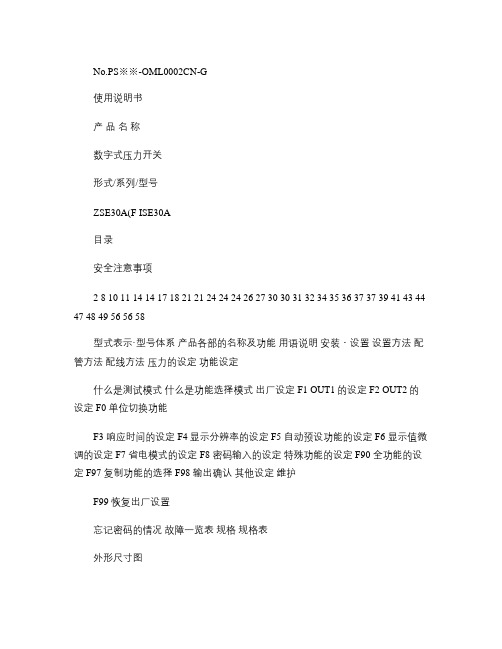
No.PS※※-OML0002式/系列/型号
ZSE30A(F ISE30A
安全注意事项
2 8 10 11 14 14 17 18 21 21 24 24 24 26 27 30 30 31 32 34 35 36 37 37 39 41 43 44 47 48 49 56 56 58
SMC 真空系统
SMC 真空系统一、引言本文档旨在介绍和说明使用和维护SMC真空系统的相关信息。
SMC真空系统是一套先进的真空设备,广泛应用于工业生产和实验研究领域。
本文档将按照以下章节对SMC真空系统进行详细描述。
二、系统概述本章节介绍SMC真空系统的总体结构和主要组成部分。
包括真空泵、真空压力控制器、真空传感器和其他相关设备。
详细描述每个组件的功能和特点。
三、安装与调试本章节详细说明SMC真空系统的安装和调试流程。
包括安装位置的选择、管道连接、电源接线等。
同时提供调试方法和常见故障排除步骤。
四、操作指南本章节提供SMC真空系统的操作指南。
包括系统启动和关闭、真空泵开启和停止、真空度调节、压力控制器的设置等操作步骤。
同时针对不同实际应用场景给出操作注意事项和优化建议。
五、维护与保养本章节介绍SMC真空系统的日常维护和保养要点。
包括定期清洁、润滑和更换部件、维护记录的保存等。
同时提供常见故障的排查和解决方法。
六、安全注意事项本章节列出使用SMC真空系统时需要注意的安全事项。
包括高压风险、电气安全、防止污染等方面的指导。
同时提供应急处理措施和紧急停机程序。
七、附件1、SMC真空系统安装图纸2、SMC真空系统维护记录表格3、SMC真空系统产品说明书八、法律名词及注释1、涉及的法律名词:a:真空设备:指用来创造和维持一定低压环境的设备,以进行各种实验和工业生产过程。
b:压力控制器:指用来控制和调节真空系统压力的设备,以满足各种工艺需求。
c:安全事项:指使用真空系统时需要遵守和注意的各种安全原则和规定。
2、注释:a: SMC真空系统:SMC公司生产的一套完整的真空设备解决方案。
b:维护记录表格:用于记录每次维护和保养工作的表格,以便开展合理的设备维护管理。
SMC 真空系统

SMC 真空系统SMC 真空系统1·系统概述1·1 系统定义SMC 真空系统是一种专为工业应用而设计和制造的真空设备,旨在实现高效的真空处理和控制。
1·2 系统组成SMC 真空系统由以下几个主要组件组成:1·2·1 真空泵:负责产生和维持所需真空度的装置。
1·2·2 阀门:用于调节真空系统中气体的流动。
1·2·3 传感器:用于监测真空度和其他相关参数。
1·2·4 控制器和仪表:用于控制和监测系统的运转状态。
1·2·5 管道和接头:连接各个组件并确保气体的有效流动。
2·系统安装与调试2·1 设备准备2·1·1 确定系统安装位置和布局。
2·1·2 检查设备和零部件是否完好。
2·1·3 准备所需的安装工具和材料。
2·2 安装步骤2·2·1 安装真空泵和阀门。
2·2·2 连接管道和接头。
2·2·3 安装传感器和控制器。
2·2·4 连接电源线和通信线缆。
2·2·5 进行系统的初步调试。
3·系统操作与维护3·1 系统启动和停止3·1·1 启动系统:按照指示,逐次启动真空泵、控制器和其他组件。
3·1·2 停止系统:按照指示,逐次停止各个组件,确保系统安全关闭。
3·2 真空度控制3·2·1 设置真空度目标值。
3·2·2 调节阀门和真空泵的运行状态以控制真空度。
3·2·3 监测真空度,并及时采取相应措施保持真空度稳定。
3·3 维护与保养3·3·1 定期检查和清洁系统组件。
SMC产品培训教程---真空

真空过滤器
•进出口方向不得装反,配管处不得有泄漏 •真空过滤器内流速不大,空气中的水分不会凝结,故该过滤器无需分 水功能 •不要用AF系列过滤器取代ZF系列过滤器,避免性能变差
真空发生器
分类
盒式(B型) 在排气口带消声器
按外形分:
管式(D型) 不带消声器
标准型(S型)
按性能分:
大流量型(L型)
Z U
快换接头式
按连接方式分:
椎管螺纹连接式
系 列
Z H 系 列
ZH 07 B S ZH 07 D S
06
06
01
01
01
喷嘴口径 最高真空压力
真空口接管口径
供气口接管口径
排气口接管口径
备注
真空调压阀
调节真空压力,重量轻,安装方便 IRV
• 现状:
以真空压力为动力源, 已成为实现自动化的 一种手段
概 述
• 用途: 对于任何具有光滑表面的物体,特别对于非铁、非金属且不适合加紧的物体,
如薄的纸张、塑料膜,铝箔,易碎的玻璃及其制品,集成电路等微型精密零件, 都可使用真空吸附
• 真空发生装置的分类:真空泵
系
统
构
成
元
ZM系列
件
ZR系列
电子元件等小件 的真空搬运用
也可用于真空泵 系统
使用2段式真空发 生器,提高了真 空发生器的使用 效率
使用双电控制阀, 有自保持功能
模块式设计,必 要的功能可组合
也可用于真空泵 系统
真空发生 器喷嘴口 径(mm)
0.5~1.0
0.5~1.3
1.0~2.0
构成元件
smc真空发生器原理

smc真空发生器原理
SMC真空发生器基于二次侧叶片的原理工作。
其工作原理如下:
1. 真空发生器中的马达通过传动机构驱动叶轮转动。
2. 当马达转动时,叶轮在瞬间加速,使得发生器内部产生一个高速旋转的气流。
3. 由于气流的离心力作用,气流中的气体分子向外部被抛出,产生一个真空区域。
4. 同时,真空发生器的进气口处有入口,可以通过管道与被抽气体连接。
5. 被抽气体进入发生器后,受到气流的作用,被抛出真空区域,从而被抽取出来。
6. 被抽气体在发生器内部与气流不断碰撞、抛射和膨胀缩小,并且在此过程中气体温度会升高。
7. 最后,被抽取的气体从发生器的排气口排出,达到真空
抽取的目的。
通过以上工作原理,SMC真空发生器可以实现对气体的抽
取和形成真空的目的。
它的优点包括工作效率高、噪音低、体积小、使用寿命长等。
SMC真空发生器维护和修理保养工作原理

SMC真空发生器维护和修理保养工作原理SMC真空发生器是一种基于真空技术工作的设备,重要用于产生环境中的真空。
正常维护和保养是保证SMC真空发生器长期稳定工作的关键。
本篇文章将介绍SMC真空发生器的工作原理,以及维护和修理保养过程中需要注意的细节。
一、SMC真空发生器的工作原理SMC真空发生器是通过电磁阀或机械泵抽气将容器内的气体抽出来,从而形成真空的过程。
其中,电磁阀是真空度不超过0.1MPa 的情况下使用的一种针型阀门,可以快速地汲取容器内的气体,同时也可用于泵出较小的气体。
机械泵则重要是通过高速旋转的叶轮将空气抽出容器。
这种技术可以生成更高的真空度。
在SMC真空发生器中,真空度是通过压力计测量的。
在抽出空气之后,压力计会测量容器内的气压,从而判定是否达到预定的真空度。
一般情况下,真空度越高,则抽出空气的难度也就越大。
二、SMC真空发生器维护和修理保养的几个注意要点1. 防止机械泵的过热长时间使用机械泵会导致其过热,进而影响SMC真空发生器的工作效果。
为了防止机械泵的过热,需要引导其正常降温。
可以通过安装附加的风扇和散热器来改善散热效果。
2. 定期更换机械泵油机械泵油是中重负荷部件,需要定期更换以保证设备的正常运行。
建议在每500小时的使用后进行一次更换,并检查泵内是否有杂质和氧化物。
3. 定期检查密封性SMC真空发生器的密封性对于环境稳定操作来说非常紧要。
设备使用后,需要定期检查全部泄漏点的密封性。
4. 定期清洗容器内的杂质SMC真空发生器的容器内也简单积累杂质,这些杂质对真空度的影响很大。
为了维护设备的正常工作,需要定期清洗容器内的杂质。
5. 替换电磁阀电磁阀是简单损坏的部件,需要定期更换。
在更换过程中,需要注意与原件型号匹配,而且精准明确地调整其位置和功能。
6. 检查真空密度在保养维护工作中,检查真空密度时是至关紧要的步骤。
通过定期检测容器内的真空密度,可以发觉很多问题,如泄漏、磨损和设备损坏等。
- 1、下载文档前请自行甄别文档内容的完整性,平台不提供额外的编辑、内容补充、找答案等附加服务。
- 2、"仅部分预览"的文档,不可在线预览部分如存在完整性等问题,可反馈申请退款(可完整预览的文档不适用该条件!)。
- 3、如文档侵犯您的权益,请联系客服反馈,我们会尽快为您处理(人工客服工作时间:9:00-18:30)。
27
SMCGZ Pneumatics Ltd.
真空系统
•从吸盘直径、真空度求不含安全率的理论吸吊力。 •然后,理论吸吊力除以安全率,求吸吊力。 •吸吊力=理论吸吊力×1/t
INTERNATIONAL TRAINING
10
SMCGZ Pneumatics Ltd.
真空泵系统
INTERNATIONAL TRAINING
11
SMCGZ Pneumatics Ltd.
切换阀:接通或断开真空压力源。 一般使用二位二通阀。
破坏阀:可控制吸盘对工件的吸着和脱离, 一般使用二位三通阀。
INTERNATIONAL TRAINING
28
SMCGZ Pneumatics Ltd.
真空系统
INTERNATIONAL TRAINING
29
SMCGZ Pneumatics Ltd.
真空系统
INTERNATIONAL TRAINING
30
SMCGZ Pneumatics Ltd.
真空系统
橡胶的材质和特性
INTERNATIONAL TRAINING
p 4wt 4196 4 0.0665Mpa D2n 502 6
W:负载的重力(N) t:安全系数;水平吸为4以上,垂直吸为8以上;
D:吸盘直径(mm); n:吸盘个数。
38
SMCGZ Pneumatics Ltd.
真空系统
真空系统案例选型
INTERNATIONAL TRAINING
INTERNATIONAL TRAINING
23
SMCGZ Pneumatics Ltd.
真空系统选型
INTERNATIONAL TRAINING
24
SMCGZ Pneumatics Ltd.
真空系统选型
INTERNATIONAL TRAINING
25
SMCGZ Pneumatics Ltd.
真空系统选型
活塞式
螺杆式
离心式
6
SMCGZ Pneumatics Ltd.
真空系统
产生真空的设备
INTERNATIONAL TRAINING
真空发生器
利用压缩空气的流动而形成一定真空度的气动元件.最大 真空可达-88kpa.
盒式真空发生器ZH系列
管式真空发生器ZU系列
7
SMCGZ Pneumatics Ltd.
Ф 16 2.01 17.1 16.1 15.1 14.1 13.1 12.1 11.1 10.1 9.05 8.04
Ф 20 3.14 26.7 25.1 23.6 22.0 20.4 18.8 17.3 15.7 14.1 12.6
Ф 25 4.91 41.7 39.3 36.8 34.4 31.9 29.5 27.0 24.6 22.1 19.6
Ф 32
Ф 40
Ф 50
8.04
12.6
19.6
68.3
107
167
64.3
101
157
60.3
94.5
147
56.3
88.2
137
52.3
81.9
127
48.2
75.6
118
44.2
69.3
108
40.2
63.0
98.0
36.1
56.7
88.2
32.2
50.4
78.4
39
SMCGZ Pneumatics Ltd.
一般使用二位二通阀。
INTERNATIONAL TRAINING
15
SMCGZ Pneumatics Ltd.
INTERNATIONAL TRAINING
16
SMCGZ Pneumatics Ltd.
真空系统
真空系统组成
真空调压阀
INTERNATIONAL TRAINING
调节真空系统压力并保持其稳定,通用于真空泵系统中。
4
SMCGZ Pneumatics Ltd.
真空系统
真空的应用
集成电路的接合
拾取及传送
INTERNATIONAL TRAINING
电路元件安装
传送印刷纸张
5
SMCGZ Pneumatics Ltd.
真空系统
产生真空的设备
INTERNATIONAL TRAINING
真空泵
吸入口形成负压,排气口直接通大气,两端压力比很 大的抽除气体的机械;最大真空可达-101.33kpa.
压
力
Pvx63%
P
T1
2T1
3T1
T1 达到时间(sec) T2
Pv:最终真空压力
T1:到达最终真空压力Pv的63%的时间 3T1:到达最终真空压力Pv的95%的时间
41
SMCGZ Pneumatics Ltd.
真空系统
真空系统案例选型
INTERNATIONAL TRAINING
3.计算真空发生器最大吸入流量Qe
12
SMCGZ Pneumatics Ltd.
INTERNATIONAL TRAINING
13
SMCGZ Pneumatics Ltd.
真空发生器系统----组件
INTERNATIONAL TRAINING
14
SMCGZ Pneumatics Ltd.
真空发生器系统----组件
供给阀:供给真空发生器压缩空气的阀。 破坏阀:破坏吸盘内的真空状态,使工件脱离吸盘。
INTERNATIONAL TRAINING
26
SMCGZ Pneumatics Ltd.
真空系统
INTERNATIONAL TRAINING
•根据算出的吸盘的吸吊力求吸盘的直径。 •有时,计算值作为参考值,还要进行必要的吸着试验来确认。 •吸吊力的计算要根据工件的重量及移动时(上升、停止、回转等)的加速度 产生的惯性力,给予充分的裕量。
17
SMCGZ Pneumatics Ltd.
真空系统
真空系统组成
真空压力开关
INTERNATIONAL TRAINING
确保安全吸住工件的真空压力,输出电信号给真空控制系统。
ZSP1
ZSE2
ZSE3
PSE1100
ZSE30A
18
SMCGZ Pneumatics Ltd.
真空系统
真空系统组成
INTERNATIONAL TRAINING
真空系统
真空发生器工作原理
INTERNATIONAL TRAINING
8
SMCGZ Pneumatics Ltd.
真空系统
INTERNATIONAL TRAINING
•不仅有单段式真空发生器,还有由多个真空发生器组成的多段式真空发生器。 •多段式真空发生器,可以增加吸入流量,比单段式真空发生器的吸入流量大。
真空吸盘理论吸力表
w p s 0.1 1 T
吸盘直径(mm) 吸盘的面积 -85 -80 -75 -70(-525) -65(-488)
kPa -60(-450) -55(-413) -50(-375) -45(-338) -40(-300)
Ф2 0.03 0.26 0.25 0.23 0.22 0.20 0.19 0.17 0.16 0.14 0.12
v d 2l
4000
d:配管的内径(mm)
L:配管的长度(m)
T:真空到达时间
40
SMCGZ Pneumatics Ltd.
真空系统
真空系统案例选型
INTERNATIONAL TRAINING
响应时间
T1
60v Q
T2 3T1
供给阀 (切换阀)
的动作
ON OFF
Pv
真 空
Pvx95%
34
SMCGZ Pneumatics Ltd.
INTERNATIONAL TRAINING
35
SMCGZ Pneumatics Ltd.
INTERNATIONAL TRAINING
36
SMCGZ Pneumatics Ltd.
INTERNATIONAL TRAINING
37
SMCGZ Pneumatics Ltd.
INTERNATIONAL TRAINING
单向阀 当供给阀停止供气时,保持吸盘内的真空压力。
安全考虑,可延缓被吸吊工件脱落的时间。应选用流通能力大、开启压力 低(0.01Mpa)的单向阀,SMC公司有AK系列的单向阀可选用。
节流阀 用于控制真空破坏的快慢,节流阀出口压力不得高于0.5Mpa,可使用AS
真空系统
真空系统案例选型
INTERNATIONAL TRAINING
• 当工件吸着有泄漏时,最大吸入流量应按以下标准计算
Qm
ax
(2
~
3)Q
(2
~
3)(60v T
QL
)
QL 11.1 SL
Qe 28.5 17 L / min
真空发生器:Q1 CQ Qe
真空切换阀:Q1 CQ 11.1Sc
Qe:真空发生器最大吸入流量,L/min(ANR)
SC:真空切换阀的有效面积,mm2
CQ
1 2
~
1 3
一般取 CQ
1 2
;
若真空管路流动阻力偏大,可取
CQ
1 3
42
SMCGZ Pneumatics Ltd.