HEVC模式选择过程与帧内编码
HEVC模式选择过程与帧内编码

HEVC模式选择过程与帧内编码
HEVC模式选择过程
HEVC通过遍历候选模式获得最佳的预测模式,过程如下(LCU:64X64,SCU:8X8):
1.当前编码单元尺寸上进行帧内模式的率失真代价计算,遍历不同的模式,得到其代价最小的预测模式;
2.将当前尺寸分割成4个更小的CU尺寸,并进行第一步的计算;
3.判断,若当前块尺寸大于SCU,则转到步骤2;若等于8X8的尺寸,直接跳到第4步;
4.对所有划分方式进行率失真的比较,选出最优划分方式,存储其率失真代价最小的情况。
HEVC帧内编码
就是一个递归的过程,首先CTU进行帧内编码的模式搜索,计算出相应的率失真代价RD cost_1,然后把CTU划分为四个子CU,对每一个子CU按照之前对CTU预测得到的模式来进行计算率失真代价RD cost_2。
比较二者的值,若RD cost_1<="" p="">
因此一个64X64的CU,如果进行深度为4的划分话,一共会形成85个CU,深度遍历四叉树的每个节点,计算出四叉树上每个节点的权重,即当前CU的RD cost。
若当前CU的所有划分的RD cost之和小于不划分的RD cost,则当前CU在编码的时候进行划分。
通过这个算法,计算出使整个64X64的RD cost最小的划分路径,用于编码。
HEVC帧内预测编码

HEVC帧内预测编码(一)帧内预测编码原理1、HEVC的基本编码框架如图2.1所示,其核心编码模块包括:帧内/间预测、变换和量化、炮编码、环内滤波等等。
编码器控制模块根据视频顿中不同图像块的局部特性,选择该图像块所釆用的编码模式。
(1)对帧内预测编码的块进行频域或空域预测;(2)对帧间预测编码的块进行运动补偿预测;(3)预测的残差再通过变换和量化处理形成残差系数,最后通过熵编码器生成最终的码流。
HEVC的基本编码框架图1、基本概念(1)编码是以尺寸为]6 x 16的宏块(MB)为单位进行的。
一个宏块由一个尺寸为16 X 16的亮度像素块和两个尺寸为8x8的色度像素块Cb和Cr组成。
根据预测模式的不同,一个宏块可以划分为多个子块进行预测。
(2)编码单元(CU):每个CU包含着与之相关联的预测单元(PU)和变换单元(TU)。
3、帧内预测模式(1)帧内预测是指通过当前帖中已编码块的重构图像预测当前块。
HEVC—共定义了35种帧内预测模式。
HEVC帧内预测模式(2)参考像素的选择设当前块的左上角第一个像素为坐标原点,(x,y)为坐标值,,R x y 表示参考像素,P(x,y)表示当前块的预测像素。
(3)模式选择利用拉格朗日率失真优化模型(RDO ):J =D +R λ⋅选择最合适的帧内预测模式。
(4)模式编码(a )建立一个帧内预测候选列表candModeList,表中有三种候选预测模式,用于存储相邻PU 的预测模式;(b )candModeList 建立完成后,可利用该列表对当前PU 模式信息进行编码。
4、帧内预测过程理论上,HEVC 的帧内预测可以分为三个步骤:1、判断当前TU 相邻参考像素是否可用,获取相邻参考像素;2、对参考像素进行滤波;3、根据滤波后的参考像素以及预测模式,计算当前TU 的预测像素值。
在代码实现中,这几部分分别对应,如以下的流程图所示:(二)源代码:1、fillReferenceSamples 函数它主要功能是在真正进行帧内预测之前,使用重建后的Yuv 图像对当前PU 的相邻样点进行赋值,为接下来进行的角度预测提供参考样点值。
基于HEVC的帧内快速模式选择算法
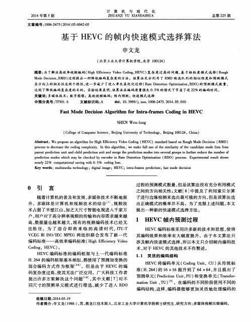
Ke y wo r d s:mu l t i me d i a t e c h n o l o g y;d i g i t l a i ma g e ;HE VC;i n t r a — f r a me s p r e d i c t i o n;f a s t mo d e d e c i s i o n
p r o c e s s t o d e c r e a s e t h e c o d i n g c o mp l e x i t y .I n t h i s lg a o i r t h m ,w e ma k e f u l l u s e f o he t s i mi l a r i t y o f he t c a n d i d a t e mo d e l i s t s f r o m p a r e n t p r e d i c t i o n u n i t a n d c h i l d p r e d i c t i o n u n i t a n d me r g e t h e p r e d i c t i o n mo d e s i n t o s e v e r a l g r o u p s o t f u t r h e r r e d u c e t h e n u mb e r f o
申文龙
( 北京工业 大学计算机 学院, 北京 1 0 0 1 4) 2
摘要 : 为 了解决高效率视频编码( H i g h E ic f i e n c y V i d e o C o d i n g , HE V C ) 复杂度 过 高的 问题 , 基 于粗 粒度 模式 选择 ( R o u g h Mo d e D e c i s i o n , R MD) 过程提 出一种 降低 编码 复杂度 的方法。该算法 充分利 用 了 R MD候 选队 列的相似 程度和 预测模 式 在方 向上 的相 关性 这两个特性 , 进一步减 少了进入 率失真优 化过程 ( R a t e D i s t o r t i o n O p t i m i z a t i o n , R D O) 的预 测模 式数 量 ,
利用纹理结构的HEVC快速帧内模式选择算法

URN AL O F S I GNAL P RO C ES S I NG
V0 1 . 31 No . 9 S e p.2 01 5
2 0 1 5年 9月
利 用纹 理 结 构 的 HE VC快 速 帧 内模 式 选 择 算 法
A b s t r a c t : T h e m o s t p r o m i n e n t f e a t u r e o f i n t r a p r e d i c t i o n i n t h e H i . s h E ic f i e n c y V i d e o C o d i n g( H E V C)i s a d o p t i n g t h e t r e e s t r u c t u r e d c o d i n g u n i t( C U) , w h o s e s i z e c a n b e c h a n g e d f r o m 6 4 × 6 4 t o 8 x 8 , a n d 3 5 i n t r a p r e d i c t i o n m o d e s .C o n s e q u e n t -
关键 词 :视频编码 ;高性能视频编码 ;帧 内编码 ;快速模式选择 中图分类号 :T N 9 1 9 . 8 1 文献标识码 :A 文章编号 :1 0 0 3 — 0 5 3 0 ( 2 0 1 5 l 0 9 一 l 0 9 4 — 0 7
Fa s t Mo d e De c i s i o n f o r HEVC I n t r a Co d i n g Us i n g Te x t u r e I n f o r ma t i o n
l y ,t he i n t r a mo d e d e c i s i o n p r o c e s s i n HE VC i s p e r f o me r d u s i n g a l l he t p o s s i b l e C U s i z e s a n d p r e d i c t i o n mo d e s t o f i n d he t o p t i ma l c o d i n g mo d e .T h i s a c h i e v e s t h e h i g h e s t c o d i n g e ic f i e n c y b u t a t t h e c o s t o f a v e r y h i g h c o mp u t a t i o n l a c o mp l e x i t y . T o r e d u c e t h e c o mp u t a t i o n l a c o mp l e x i t y o f i n t r a f r a me p r e d i c t i o n,f r o m t h e v e r s i o n 2 . 0,t h e HM r e f e r e n c e s o f t wa r e h a s a .
简述hevc帧内预测流程
简述hevc帧内预测流程英文回答:HEVC (High Efficiency Video Coding) is a video compression standard that utilizes various coding tools to improve coding efficiency. One of the important codingtools in HEVC is intra prediction, which is used to exploit spatial redundancy within a frame. The intra prediction process is responsible for generating a prediction for each coding unit within a frame based on the neighboring already reconstructed samples. This prediction is then subtracted from the original signal to obtain the residual, which is further encoded using transform and quantization processes.The HEVC intra prediction process involves several steps. First, the encoder partitions the frame into coding units (CU) of various sizes, such as 64x64, 32x32, 16x16, and 8x8. Then, for each CU, the encoder selects aprediction mode from a predefined set of angular modes and planar mode. The angular modes are used to capture diagonaland horizontal/vertical directional patterns, while the planar mode captures smooth variations in the signal.After selecting the prediction mode, the encoder performs prediction by using the samples already reconstructed to the left and above the current block. The prediction is generated by applying the selected mode tothe neighboring samples. Once the prediction is obtained, the encoder calculates the residual by subtracting the prediction from the original signal. The residual is then transformed and quantized for entropy coding.In summary, the HEVC frame intra prediction process involves partitioning the frame into coding units,selecting a prediction mode for each coding unit,generating the prediction based on neighboring samples, calculating the residual, and further encoding the residual. This process helps in reducing spatial redundancy and improving compression efficiency.中文回答:HEVC(高效视频编码)是一种视频压缩标准,利用各种编码工具来提高编码效率。
一种hevc帧内编码的快速算法
一种hevc帧内编码的快速算法随着高清视频编码的应用广泛,视频编码技术也不断创新。
HEVC(High Efficiency Video Coding)是一种新兴的视频编码标准,它的编码效率比先前的编码标准高出30%以上,但它的编码时间也随之增加。
因为HEVC使用了更复杂的算法来提高其编码效率,所以导致了更长时间的编码过程。
为了解决这个问题,需要一种能够快速进行HEVC帧内编码的算法。
HEVC帧内编码是一种先将一帧视频分成小块,然后对每个块进行处理的算法。
对于每个块,HEVC会选择最适合它的预测模式,并根据这个预测模式对其进行编码。
然而,这个编码过程需要进行一系列的计算,包括变换、量化、熵编码等,而这些计算过程都需要花费巨大的时间。
因此,为了提高编码效率,需要一种能够快速进行这些计算过程的算法。
一种基于快速傅里叶变换(FFT)的算法被提出来作为解决方案。
该算法首先对每个块进行FFT变换,然后使用选择性位数算法(SNS)去掉变换后的系数中的一些冗余信息。
接下来,使用一种自适应的变换系数缩放技术,使得每个块的系数能够更好地适应其熵编码模型,并且可以优化量化过程。
最后,使用一种反变换技术将变换后的块转换为它们的原始块。
这种算法通过FFT的快速计算能够大幅度缩短计算时间,同时,通过SNS算法去掉冗余信息以及自适应的缩放技术和优化量化过程,可以增加压缩比和降低码率。
因为这种算法可以快速高效地进行处理,所以可以用来加速HEVC帧内编码的过程。
除了FFT算法之外,还有其他可用的算法,例如多项式展开算法以及子采样算法。
这些算法也可以用于加速HEVC帧内编码。
然而,FFT算法的优势在于它可以快速高效地计算出变换系数,并且可以更好地适应二维情况下的数据处理。
总而言之,快速HEVC帧内编码算法是一种提高编码效率的重要工具。
与传统的编码方法相比,它具有更高的压缩率、更快的速度以及更高的质量。
因此,研究和开发快速HEVC帧内编码算法是非常必要和重要的。
视频编码与HEVC中帧内编码的简要介绍
视频编码与HEVC中帧内编码的简要介绍作者:李晨曦来源:《数码设计》2019年第09期摘要:视频编码又称视频压缩。
随着多媒体时代与网络时代的到来,用户对数字媒体的要求越发提高。
由于未经压缩的视频数据过于庞大,视频压缩技术应运而生并随着软硬件设备的迭代而逐渐进化。
本文以H.264/AVC编码器原理为基础简单介绍了视频编码的基本原理,并与新一代视频编码标准H.255/HEVC的帧内编码模块进行了比较。
关键词:视频编码;HEVC;H.264;帧内编码中图分类号:TP13;;;;; 文献标识码:A;;;;; 文章编号:1672-9129(2019)09-0056-03A brief introduction of video coding and intra coding in HEVCChenxi Li(School of Computer Science, Southwest Petroleum University, Chengdu Sichuan 610500, China)Anstract: Video coding is also known as video compression. With the advent of the multimedia and network era, users' demands for digital media have increased. Since uncompressed video content is too large, video compression technology has emerged and evolved with the iteration of hardware and software. This paper briefly introduces the basic principle of video coding and compares it with the intra-frame coding module of the new generation video coding standardH.265/HEVC.Key words: Video coding; H.264/AVC; H.265/HEVC; intra coding1; 视频压缩简介隨着多媒体时代的到来,用户对视频质量与传输速度的要求也越来越高。
一种新的用于屏幕图像编码的HEVC帧内模式
i n a c e r t a i n l e n g t h d i c t i o n a r y wi n do w b y u s i n g Ha s h t a b l e . Wh e n de c o d i n g , a c c o r di n g t o t h e p i x e l s s t r i n g ma t c h i n g
典窗 口内,利用 散列表 ,对当前 Cu内的像素 ,进行 串搜索和 匹配 ;解码 时,根据像素 串匹配的距离和匹配长度 ,
在重建缓存 内复制相应位置像素重建 当前 C U像素 。实验结果表 明, 在 编码 复杂度增 加很 少的情况 下,对于典型的
屏幕图像测试序列,在全帧内( A l l I n t r a , A I ) ,随机接) k ( R  ̄d o m A c c e s s , R A ) ,低 ̄i g ( L o w — d e l a y B , L B ) 3 种配
置下 , 有损编码模式 比 HE VC分别节 省码率 1 5 . 1 %, 1 2 . 0 %, 8 . 3 %, 无损编码模式分别节省码率 2 3 . 3 %, 1 4 . 9 %, 1 1 . 6 %。 关键词 :高效视 频编码 ;屏幕 图像编码 ;字典编码 ;散列表
中图分类号: T N 9 1 9 . 8
基于率失真优化的HEVC帧内编码模式选择

现代电子技术Modern Electronics Technique2018年6月15日第41卷第12期Jun.2018Vol.41No.120引言在大数据信息时代,随着视频技术的发展和应用,海量的视频信息深入到人们的工作和生活的方方面面中。
随着高清(HD )、超高清(UHD )、3D 和多视点(Multi⁃View )视频的普及,针对海量视频数据的传输和存储,需要有高效的视频编码方法来解决这一问题。
2013年由国际电信组织(International Telecommu⁃nication Union ,IUT )和运动图像专家组(Moving Picture Experts Group ,MPEG )联合成立的JCT⁃VC (Joint Collab⁃orative Team⁃Video Coding )组织提出新一代高效视频编码标准(High Efficiency Video Coding ,HEVC )[1]。
HEVC包含着最新的视频编码技术,比上一代H.264/AVC 在同样的编码质量下,码率[2]能够节约50%以上。
高压缩比、低码率和特有的并行处理设计等优点,使得HEVC 快速在各类视频业务中获得广泛应用。
人类通过视觉获取大部分信息,图像和视频是信息最重要的载体。
数字视频(Digital Video )是由一系列静止图像构成,通过一帧帧快速播放的方式为用户呈现出一个动态场景。
但是海量的视频所携带的数据量是非常庞大的,例如,分辨率为1920×1080的高清视频,它的帧率为30f/s 。
若一个像素值用8个比特数来表示,则亮度分量对应的码率约为1920×1080×30×8≈498Mbit/s ,这么大的数据量造成传输网络和存储介质难以承受。
因此,HEVC 有效的视频压缩或编码技术在多媒体应用方面,变得尤为重要。
视频编码的性能基本取决编码码率、压缩失真和计算复杂度这三个因素。
HEVC-H.265帧内编码关键技术软硬件优化
HEVC-H.265帧内编码关键技术软硬件优化HEVC/H.265帧内编码关键技术软硬件优化摘要:高效视频编码(High Efficiency Video Coding,HEVC)是当前最新的国际视频编码标准,其目标是在不损失视觉质量的情况下,显著提高视频编码的效率。
其中,帧内编码是HEVC的重要组成部分,对编码效率起着至关重要的作用。
本文主要讨论HEVC/H.265帧内编码的关键技术和软硬件优化方法,旨在提高帧内编码的性能和效率。
1. 引言近年来,随着高清视频的普及和互联网的高速发展,对视频编码的需求和要求也越来越高。
HEVC作为一种先进的视频编码标准,以其出色的压缩效率和高质量的解码性能被广泛应用于多媒体应用中。
帧内编码是HEVC中最重要的编码模式之一,因此对其进行技术优化和硬件加速具有重要意义。
2. HEVC/H.265帧内编码原理HEVC/H.265帧内编码采用了一系列创新的算法和技术,包括预测、变换、量化和编码等过程。
预测是帧内编码的核心过程,通过利用空间和时间上的相关性对当前帧像素进行预测,以减小编码器所需的位数。
变换过程通过将预测残差从空域转换为频域,使得编码的残差更加易于压缩。
量化和编码过程则是对变换系数进行量化和熵编码,以减小编码后的数据量。
3. 帧内编码关键技术为提高HEVC/H.265帧内编码的效率和性能,需要研究和优化以下几个关键技术:3.1 预测算法预测算法是帧内编码的核心,准确的预测可以显著降低编码残差的能量。
常用的预测算法包括帧内预测、帧间预测和运动补偿。
在帧内预测中,通常使用邻域像素值进行预测,而帧间预测则通过参考帧进行预测。
运动补偿则可以根据运动矢量对编码残差进行补偿,从而提高编码的效率。
3.2 变换算法变换算法是将预测残差从空域转换为频域的关键过程。
HEVC/H.265中采用了一种新的变换算法——倒装正交转换(Inverse Discrete Cosine Transform,IDCT)。
intraprediction,HEVC里面的帧内编码详解

Intra Coding of the HEVC StandardJani Lainema,Frank Bossen,Member,IEEE,Woo-Jin Han,Member,IEEE,Junghye Min,and Kemal UgurAbstract—This paper provides an overview of the intra coding techniques in the High Efficiency Video Coding(HEVC)standard being developed by the Joint Collaborative Team on Video Coding (JCT-VC).The intra coding framework of HEVC follows that of traditional hybrid codecs and is built on spatial sample prediction followed by transform coding and postprocessing steps.Novel features contributing to the increased compression efficiency include a quadtree-based variable block size coding structure, block-size agnostic angular and planar prediction,adaptive pre-and postfiltering,and prediction direction-based transform coefficient scanning.This paper discusses the design principles applied during the development of the new intra coding methods and analyzes the compression performance of the individual tools. Computational complexity of the introduced intra prediction algorithms is analyzed both by deriving operational cycle counts and benchmarking an optimized ing objective metrics,the bitrate reduction provided by the HEVC intra coding over the H.264/advanced video coding reference is reported to be 22%on average and up to36%.Significant subjective picture quality improvements are also reported when comparing the resulting pictures atfixed bitrate.Index Terms—High Efficiency Video Coding(HEVC),image coding,intra prediction,Joint Collaborative Team on Video Coding(JCT-VC),video coding.I.IntroductionT HE TWO prominent international organizations specify-ing video coding standards,namely ITU-T Video Coding Experts Group(VCEG)and ISO/IEC Moving Picture Experts Group(MPEG),formed the Joint Collaborative Team on Video Coding(JCT-VC)in April2010.Since then,JCT-VC has been working toward defining a next-generation video coding standard called High Efficiency Video Coding(HEVC).There are two major goals for this standard.First,it is targeted to achieve significant improvements in coding efficiency com-pared to H.264/Advanced Video Coding(A VC)[1],especially when operating on high-resolution video content.Second,the standard should have low enough complexity to enable high-resolution high-quality video applications in various use cases, Manuscript received April13,2012;revised July18,2012;accepted August 21,2012.Date of publication October2,2012;date of current version January 8,2013.This work was supported by Gachon University under the Research Fund of2012GCU-2011-R288.This paper was recommended by Associate Editor O.C.Au.(Corresponding author:W.-J.Han.)inema and K.Ugur are with the Nokia Research Center,Tampere 33720,Finland(e-mail:inema@;kemal.ugur@).F.Bossen is with DOCOMO Innovations,Inc.,Palo Alto,CA94304USA (e-mail:bossen@).W.-J.Han is with Gachon University,Seongnam461-701,Korea(e-mail: hurumi@).J.Min is with Samsung Electronics,Suwon442-742,Korea(e-mail: jh643.min@).Color versions of one or more of thefigures in this paper are available online at .Digital Object Identifier10.1109/TCSVT.2012.2221525including operation in mobile environments with tablets and mobile phones.This paper analyzes different aspects of the HEVC intra coding process and discusses the motivation leading to the selected design.The analysis includes assessing coding efficiency of the individual tools contributing to the overall performance as well as studying complexity of the introduced new algorithms in detail.This paper also describes the methods HEVC utilizes to indicate the selected intra coding modes and further explains how the tools are integrated with the HEVC coding block architecture.Intra coding in HEVC can be considered as an extension of H.264/A VC,as both approaches are based on spatial sample prediction followed by transform coding.The basic elements in the HEVC intra coding design include:1)quadtree-based coding structure following the HEVCblock coding architecture;2)angular prediction with33prediction directions;3)planar prediction to generate smooth sample surfaces;4)adaptive smoothing of the reference samples;5)filtering of the prediction block boundary samples;6)prediction mode-dependent residual transform and coef-ficient scanning;7)intra mode coding based on contextual information.In addition,the HEVC intra coding process shares several processing steps with HEVC inter coding.This processing, including,e.g.,transformation,quantization,entropy coding, reduction of blocking effects,and applying sample adaptive offsets(SAO),is outside of the scope of this paper.This paper is organized as follows.Section II explains the motivation leading to the selected design for HEVC intra coding.It also describes the overall HEVC coding architecture and the new intra prediction tools introduced in the HEVC standard.Section III presents the intra mode coding and the residual coding approaches of the standard.Section IV provides complexity analysis of the introduced intra prediction processes with detailed information about the contribution of different intra prediction modes.Section V summarizes the compression efficiency gains provided by the proposed design and Section VI concludes this paper.II.HEVC Intra Coding ArchitectureIn H.264/A VC,intra coding is based on spatial extrapolation of samples from previously decoded image blocks,followed by discrete cosine transform(DCT)-based transform coding [2].HEVC utilizes the same principle,but further extends it to be able to efficiently represent wider range of textural and1051-8215/$31.00c 2012IEEEstructural information in images.The following aspects were considered during the course of HEVC project leading to the selected intra coding design.1)Range of supported coding block sizes:H.264/A VCsupports intra coded blocks up to the size of16×16 pixels.This represents a very small area in a high-definition picture and is not large enough to efficiently represent certain textures.2)Prediction of directional structures:H.264/A VC sup-ports up to eight directional intra prediction modes fora given block.This number is not adequate to predictaccurately directional structures present in typical video and image content,especially when larger block sizes are used.3)Prediction of homogeneous regions:The plane mode ofH.264/A VC was designed to code homogeneous imageregions.However,this mode does not guarantee con-tinuity at block boundaries,which can create visible artifacts.Thus,a mode that guarantees continuous pre-diction sample surfaces would be desired.4)Consistency across block sizes:H.264/A VC uses differ-ent methods to predict a block depending on the size of the block and the color component the block represents.A more consistent design is preferred,especially asHEVC supports a large variety of block sizes.5)Transforms for intra coding:H.264/A VC utilizes afixedDCT transform for a given block size.This design does not take into consideration different statistics of the pre-diction error along the horizontal and vertical directions depending on the directionality of the prediction.6)Intra mode coding:Due to the substantially increasednumber of intra modes,more efficient coding techniques are required for mode coding.The coding structure utilized for intra coding in HEVC follows closely the overall architecture of the codec.Images are split into segments called coding units(CU),predic-tion units(PU),and transform units(TU).CU represent quadtree split regions that are used to separate the intra and inter coded blocks.Inside a CU,multiple nonoverlapping PU can be defined,each of which specifies a region with individual prediction parameters.CU are further split into a quadtree of transform units,each TU having a possibility of applying residual coding with a transform of the size of the TU.HEVC contains several elements improving the efficiency of intra prediction over earlier solutions.The introduced methods can model accurately different directional structures as well as smooth regions with gradually changing sample values. There is also emphasis on avoiding introduction of artificial edges with potential blocking effects.This is achieved by adaptive smoothing of the reference samples and smoothing the generated prediction boundary samples for DC and directly horizontal and vertical modes.All the prediction modes utilize the same basic set of reference samples from above and to the left of the image block to be predicted.In the following sections,we denote the reference samples by R x,y with(x,y)having its origin one pixel above and to the left of the block’s top-leftcorner.Fig.1.Reference samples R x,y used in prediction to obtain predicted samples P x,y for a block of size N×N samples.TABLE ISpecification of Intra Prediction Modes and Associated Names Intra Prediction Mode Associated Names0Planar1DC2..34Angular(N),N=2 (34)Similarly,P x,y is used to denote a predicted sample value at a position(x,y).Fig.1illustrates the notation used. Neighboring reference samples may be unavailable for intra prediction,for example,at picture or slice boundaries,or at CU boundaries when constrained intra prediction is enabled. Missing reference samples on the left boundary are generated by repetition from the closest available reference samples below(or from above if no samples below are available). Similarly,the missing reference samples on the top boundary are obtained by copying the closest available reference sample from the left.If no reference sample is available for intra prediction,all the samples are assigned a nominal average sample value for a given bit depth(e.g.,128for8-b data). It should be noted that in addition to left,above,and above-right reconstructed samples used for H.264/A VC intra prediction,below-left side of samples(R0,N+1..R0,2N)are also used for HEVC.These samples were excluded from the H.264/A VC process as they were rarely available in the traditional macroblock-based coding structure[2],but the hierarchical HEVC coding architecture makes these candidates available more frequently.HEVC design supports a total of35intra prediction modes. Table I specifies the numbers and names associated with each mode.In this paper,intra prediction mode0refers to the planar intra prediction,mode1to DC prediction,and modes2to 34to angular prediction modes with different directionalities. Fig.2further illustrates the prediction directions associated with the angular modes.A.Angular Intra PredictionAngular intra prediction in HEVC is designed to be able to efficiently model different directional structures typicallyFig.2.HEVC angular intra prediction modes numbered from2to34and the associated displacement parameters.H and V are used to indicate the horizontal and vertical directionalities,respectively,while the numeric part of the identifier refers to the pixels’displacement as1/32pixel fractions. present in video and image contents.The number and angu-larity of prediction directions are selected to provide a good tradeoff between encoding complexity and coding efficiency for typical video material.The sample prediction process itself is designed to have low computational requirements and to be consistent across block sizes and prediction directions.The latter aims at minimizing the silicon area in hardware and the amount of code in software implementations.It is also intended to make it easier to optimize the implementation for high performance and throughput in various environments. This is especially important as the number of block sizes and prediction directions supported by HEVC intra coding far exceeds those of previous video codecs,such as H.264/A VC. In HEVC,there are four effective intra prediction block sizes ranging from4×4to32×32samples,each of which supports 33distinct prediction directions.A decoder must thus support 132combinations of block size and prediction direction. The following sections discuss in further detail different aspects contributing to the coding performance and implemen-tation complexity of the HEVC angular intra prediction.1)Angle Definitions:In natural imagery,horizontal and vertical patterns typically occur more frequently than patterns with other directionalities.The set of33prediction angles is defined to optimize the prediction accuracy based on this observation[7].Eight angles are defined for each octant with associated displacement parameters,as shown in Fig.2. Small displacement parameters for modes close to horizon-tal and vertical directions provide more accurate prediction for nearly horizontal and vertical patterns.The displacement parameter differences become larger when getting closer to diagonal directions to reduce the density of prediction modes for less frequently occurringpatterns.Fig.3.Example of projecting left reference samples to extend the top reference row.The bold arrow represents the prediction direction and the thin arrows the reference sample projections in the case of intra mode23 (vertical prediction with a displacement of−9/32pixels per row).2)Reference Pixel Handling:The intra sample prediction process in HEVC is performed by extrapolating sample values from the reconstructed reference samples utilizing a given directionality.In order to simplify the process,all sample locations within one prediction block are projected to a single reference row or column depending on the directionality of the selected prediction mode(utilizing the left reference column for angular modes2to17and the above reference row for angular modes18to34).In some cases,the projected pixel locations would have negative indexes.In these cases,the reference row or column is extended by projecting the left reference column to extend the top reference row toward left,or projecting the top reference row to extend the left reference column upward in the case of vertical and horizontal predictions,respectively.This approach was found to have a negligible effect on compression performance,and has lower complexity than an alternative approach of utilizing both top and left references selectively during the prediction sample generation process[5].Fig.3 depicts the process for extending the top reference row with samples from the left reference columns for an8×8block of pixels.3)Sample Prediction for Arbitrary Number of Directions: Each predicted sample P x,y is obtained by projecting its location to a reference row of pixels applying the selected prediction direction and interpolating a value for the sample at1/32pixel accuracy.Interpolation is performed linearly utilizing the two closest reference samplesP x,y=32−w y·R i,0+w y·R i+1,0+16>>5(1)where w y is the weighting between the two reference samples corresponding to the projected subpixel location in between R i,0and R i+1,0,and>>denotes a bit shift operation to the right.Reference sample index i and weighting parameter w y are calculated based on the projection displacement d associated with the selected prediction direction(describing the tangent of the prediction direction in units of1/32samplesand having a value from −32to +32as shown in Fig.2)asc y =(y ·d )>>5w y =(y ·d )&31i =x +c y(2)where &denotes a bitwise AND operation.It should be noted that parameters c y and w y depend only on the coordinate y and the selected prediction displacement d .Thus,both parameters remain constant when calculating predictions for one line of samples and only (1)needs to be evaluated per sample basis.When the projection points to integer samples (i.e.,when w y equals zero),the process is even simpler and consists of only copying integer reference samples from the reference row.Equations (1)and (2)define how the predicted sample values are obtained in the case of vertical prediction (modes 18to 34)when the reference row above the block is used to derive the prediction.Prediction from the left reference column (modes 2to 17)is derived identically by swapping the x and y coordinates in (1)and (2).B.Planar PredictionWhile providing good prediction in the presence of edges is important,not all image content fits an edge model.The DC prediction provides an alternative but is only a coarse approximation as the prediction is of order 0.H.264/A VC features an order-1plane prediction mode that derives a bilinear model for a block using the reference samples and generates the prediction using this model.One disadvantage of this method is that it may introduce discontinuities along the block boundaries.The planar prediction mode defined in HEVC aims to replicate the benefits of the plane mode while preserving continuities along block boundaries.It is essentially defined as an average of two linear predictions (see [8,Fig.2]for a graphical representation)P V x,y =(N −y )·R x,0+y ·R 0,N +1P H x,y =(N −x )·R 0,y +x ·R N +1,0P x,y = P Vx,y +P Hx,y +N >> log 2(N )+1 .(3)C.Reference Sample SmoothingH.264/A VC applies a three-tap smoothing filter to the ref-erence samples when predicting 8×8luma blocks.HEVC uses the same smoothing filter ([121]/4)for blocks of size 8×8and larger.The filtering operation is applied for each reference sample using neighboring reference samples.The first reference sample R 0,2N and R 2N,0are not filtered.For 32×32blocks,all angular modes except horizontal and vertical use a filtered reference.In 16×16blocks,the modes not using a filtered reference are extended to the four modes (9,11,25,27)closest to horizontal and vertical.Smoothing is also applied where the planar mode is used,for block sizes 8×8and larger.However,HEVC is more discerning in the use of this smoothing filter for smaller blocks.For 8×8blocks,only the diagonal modes (2,18,34)use a filtered reference.Applying the reference sample smoothing selectively based on the block size and directionality of the prediction is reported to reduce contouring artifacts caused by edges in the reference sample arrays [23].D.Boundary SmoothingAs noted above in the case of the H.264/A VC plane predic-tion mode,DC and angular prediction modes may introduce discontinuities along block boundaries.To remedy this prob-lem,the first prediction row and column are filtered in the case of DC prediction with a two-tap finite impulse response filter (corner sample with a three-tap filter).Similarly,the first prediction column for directly vertical prediction and the first prediction row for directly horizontal prediction are filtered utilizing a gradient-based smoothing [9].For a more complete description of the filtering process,please refer to [25].As the prediction for chroma components tends to be very smooth,the benefits of the boundary smoothing would be limited.Thus,in order to avoid extra processing with marginal quality improvements,the prediction boundary smoothing is only applied to luma component.The average coding effi-ciency improvement provided by the boundary smoothing is measured to be 0.4%in HM 6.0environment [14].E.I−PCM Mode and Transform Skipping ModeHEVC supports two special coding modes for intra coding denoted as I −PCM and transform skipping mode.In I −PCM mode,prediction,transform,quantization,and entropy coding are bypassed while the prediction samples are coded by a predefined number of bits.The main purpose of the I −PCM mode is to handle the situation when the signal cannot be efficiently coded by other modes.On the contrary,only transform is bypassed in transform skipping mode.It was adopted to improve the coding effi-ciency for specific video contents such as computer-generated graphics.HEVC restricts the use of this mode when the block size is equal to 4×4to avoid the significant design change due to this mode while this choice was proven to have most of coding efficiency benefits.F .Restrictions for Partitioning TypesHEVC intra coding supports two types of PU division,PART −2N ×2N and PART −N ×N ,splitting a CU into one or four equal-size PUs,respectively.However,the four regions specified by the partitioning type PART −N ×N can be also represented by four smaller CU with the partitioning type PART −2N ×2N .Due to this,HEVC allows an intra CU to be split into four PU only at the minimum CU size.It has been demonstrated that this restriction is associated with minimal impact in coding efficiency,but it reduces the encoding complexity significantly [3].Another way to achieve the same purpose would be reducing the CU size to 4×4with the partitioning mode PART −2N ×2N .However,this approach would result in a chroma intra prediction block size of 2×2pixels,which can be critical to the throughput of the entire intra prediction process.For this reason,the minimum allowed CU size is restricted to 8×8pixels while allowing the partitioning type PART −N ×N only in the smallest CU.G.TU-Based PredictionWhen a CU is split into multiple TU,the intra prediction is applied for each TU sequentially instead of applying theintra prediction at the PU level.One obvious advantage for this approach is the possibility of always utilizing the nearest neighboring reference samples from the already reconstructed TU.It has been shown that this property improves the intra picture coding efficiency by about1.2%[4]compared to the case of using PU border reference samples for the PU.It should be noted that all the intra prediction information is indicated per PU and the TUs inside the same PU share the same intra prediction mode.III.Mode and Residual CodingA.Mode Coding for LumaHEVC supports total33angular prediction modes as well as planar and DC prediction for luma intra prediction for all the PU sizes.Due to the large number of intra prediction modes, H.264/A VC-like mode coding approach based on a single most probable mode was not found effective in HEVC[8].Instead, HEVC defines three most probable modes for each PU based on the modes of the neighboring PUs.The selected number of most probable modes makes it also possible to indicate one of the32remaining modes by afixed length code,as the distribution of the mode probabilities outside of the set of most probable modes is found to be relatively uniform.The selection of the set of three most probable modes is based on modes of two neighboring PUs,one above and one to the left of the current PU.By default,modes of both candidate PUs are included in the set.Possible duplicates and the third mode in the set are assigned with modes planar,DC,or angular (26)in this order.In the case that both top and left PU has the same directional mode,that mode and two closest directional modes are used to construct the set of most probable modes instead.In the case current intra prediction mode is equal to one of the elements in the set of most probable modes,only the index in the set is transmitted to the decoder.Otherwise,a5-bfixed length code is used to determine the selected mode outside of the set of most probable modes.B.Derived Mode for Chroma Intra PredictionQuite often structures in the chroma signal follow those of the luma.Taking advantage of this behavior,HEVC introduces a mechanism to indicate the cases when chroma PU utilizes the same prediction mode as the corresponding luma PU.Table II specifies the mode arrangement used in signaling the chroma mode.In the case that derived mode is indicated for a PU,the prediction is performed by using the corresponding luma PU mode.In order to remove the possible redundancy in the signaling arising when derived refers to one of the modes always present,angular(34)mode is used to substitute the duplicate mode as shown in Table II.C.Syntax Design for the Intra Mode CodingHEVC uses three syntax elements to represent the luma intra prediction mode.The syntax element prev−intra−luma−pred−flag specifies whether the luma intraTABLE IISpecification of Chroma Intra PredictionModes and Associated NamesChroma intra Alternative mode,ifprediction Primary mode primary mode is equal tomode the derived mode0Planar Angular(34)1Angular(26)Angular(34)2Angular(10)Angular(34)3DC Angular(34)4Derived N/A prediction mode is matched with one of three most probable modes.When theflag is equal to1,the syntax element mpm−idx is parsed,indicating which element of the most probable mode array specifies the luma intra prediction mode.When theflag is equal to0,the syntax element rem−intra−luma−pred−mode is parsed,specifying the luma intra prediction mode as rem−intra−luma−pred−mode+N, where N is the number of elements in the most probable mode array having a mode index greater than or equal to the syntax element rem−intra−luma−pred−mode.In chroma mode coding,a1-b syntax element(0)is assigned to the most often occurring derived mode,while3-b syntax elements(100,101,110,111)are assigned to the remaining four modes.D.Intra Mode Residual CodingHEVC utilizes intra mode dependent transforms and co-efficient scanning for coding the residual information.The following sections describe the selected approaches in more detail.1)Block Size-Dependent Transform Selection:Integer trans-forms derived from DCT and discrete sine transform(DST)are applied to the intra residual blocks.A DST-based transform is selected for4×4luma blocks and DCT-based transforms for the rest.For more details on the specification of the transforms, the reader is referred to[10]and[11].Different approaches to select the transforms were studied during the course of the HEVC development.For example, an early HEVC draft utilized a method that selected the horizontal and vertical transforms separately for4×4luma blocks based on the intra prediction mode.This approach provided an average coding efficiency improvement of0.8% [10].However,it was found that the simple block size de-pended approach now adopted in the standard provides very similar coding efficiency[26].Also larger size alternative transforms were studied,but it was reported that the additional coding efficiency improvements were marginal compared to the complexity impact[27].Thus,only DCT-based transforms are utilized for block sizes larger than4×4.2)Intra Prediction Mode-Dependent Coefficient Scanning: HEVC applies adaptive scanning of transform coefficients to the transform block sizes of4×4and8×8in order to take advantage of the statistical distribution of the active coefficients in2-D transform blocks.The scan is selected based on directionality of the intra prediction mode as shownTABLE IIIMapping Table Between Intra Prediction Modes and Coefficient Scanning OrderIntra Coefficient Coefficientprediction modescanning for scanning for4×4and8×816×16and32×32Angular(6–14)Vertical DiagonalAngular(22–30)Horizontal DiagonalAll other modes Diagonal Diagonalin Table III.Vertical and horizontal scans refer to the cor-responding raster scan orders,while the diagonal scan refersto a diagonal scan from down-left to up-right direction.Theaverage coding gain from the intra mode dependent scans isreportedly around1.2%[12].plexity of Intra Prediction Toolsplexity Analysis of Decoding Process1)Analysis of Operational Cycle Counts:Defining a propermetric for theoretical analysis of complexity can be difficultas various aspects come into play.For example,if relying oncounting operations,defining what constitutes one operationlargely depends on the underlying architecture.The bit widthof each data element being processed also plays an importantrole in determining a number of gates in hardware andthe amount of parallelism achievable in software.How analgorithm is implemented can also have a significant impact.A lower number of operations is not always better.Executingfour operations in parallel may be faster and considered lesscomplex than executing three in sequence.In this section,wethus limit ourselves to a more superficial comparison of HEVCprediction modes with the H.264/A VC ones.The DC,directly horizontal,and directly vertical predic-tion modes are the ones most similar to those defined inH.264/A VC.HEVC simply defines an additional postfilteringoperation where one row and/or column of samples isfiltered.The overhead of suchfiltering becomes less with larger blocksizes,as the fraction offiltered samples becomes smaller.For predicting a block of size N×N,angular predictionrequires the computation of p=(u·a+v·b+16)>>5foreach sample,which involves two multiplications(8-b unsignedoperands,16-b result),two16-b additions,and one16-b shiftper predicted sample,for a total offive operations.In theH.264/A VC case,directional prediction may take the formp=(a+2b+c+2)>>2,which may be considered to be five operations as well.However,on some architectures,thiscan be implemented using two8-b halving add operations:d=(a+c)>>1and p=(d+b+1)>> 1.The H.264/A VC directional prediction process is thus less complex as it requires no multiplication and no intermediate value wider than9b.In the case of the plane and planar modes,consideringthe generating equations is probably not adequate,as theprediction values can be efficiently computed incrementally.For the H.264/A VC plane mode,it is expected that one16-baddition,one16-b shift,and one clip to8-b range are requiredTABLE IVDecoding Time Comparison Between HM6.0Decoder and Its Optimized Decoder Used for Further AnalysisSettingBitrate HM6.0Optimized(Mbit/s)(s)(s) BasketballDrive,QP=2271.1104.4721.97BasketballDrive,QP=378.461.60 6.98BQTerrace,QP=22179.2163.9441.42BQTerrace,QP=3721.691.0012.03Cactus,QP=22105.7120.4628.84Cactus,QP=3714.269.598.78Kimono,QP=2222.337.117.02Kimono,QP=37 3.826.94 2.88ParkScene,QP=2252.760.5314.02ParkScene,QP=377.333.90 4.35Geometric mean25.466.3410.91Sequences are each10-s long and are coded in intra-only mode.Optimized decoder is about four to nine times faster than HM.per sample.For the HEVC planar mode,three16-b additions and one16-b shift are expected per sample.The partial analysis provided here is indicative.It suggests that the HEVC intra prediction modes are more complex than the A VC modes,but not necessarily by a large amount.In the following,focus is shifted to complexity investigation based on actual implementations.2)Decoding Time of Intra Prediction in Relation to Overall Decoding Time:In afirst experiment,the percentage of de-coding time spent on intra prediction is measured.Reference encodings for the main profile of HM6.0[14]are used in the all-intra configuration[15].The experiment is focused on high-definition sequences from the JCT-VC class B test set(five 1920×1080sequences).MD5checksum computation and file output of the reconstructed pictures are disabled such that decoding times more accurately reflect time spent on actually decoding pictures.Measurements are obtained on a laptop featuring an Intel Core i5processor clocked at 2.53GHz. Software was compiled using gcc4.6.3.In addition to the HM software,an optimized decoder,based on[16],is also considered.Table IV summarizes decoding times and gives an indication of the level of optimization.For the comparative results between HEVC HM decoder and H.264/A VC JM decoder,please refer to[24],which reported that they are comparable.The fraction of decoding time used for intra prediction is further summarized in Table V.While the results obtained with HM and optimized software show some differences,they do not diverge significantly:on average roughly12%–15%of decoding time is consumed by intra prediction.The results may however be somewhat surprising in the sense that generating the reference arrays used for prediction takes more time than generating the prediction from those reference arrays.Part of this observation may be caused by the fact that in both of the tested software implemen-tations,full reference arrays are constructed,including2N+1 samples for a row above and2N+1samples for a left column. Most prediction modes do not require all these samples,and constructing only the required ones may reduce the amount of time by up to50%.。
简述hevc帧内预测流程
简述hevc帧内预测流程英文回答:HEVC (High Efficiency Video Coding) is a video compression standard that uses various techniques to improve video quality and reduce file size. One of the key processes in HEVC is frame intra-prediction, which helps to reduce spatial redundancy within a frame by predicting the current block based on neighboring samples.The frame intra-prediction process in HEVC involves several steps. First, the current block to be encoded is divided into smaller blocks, typically 4x4 or 8x8 pixels. Then, for each block, a prediction mode is selected to determine how the block will be predicted based on its neighboring samples.After the prediction mode is selected, the encoder uses the samples from previously encoded neighboring blocks to predict the current block. This prediction is subtractedfrom the original block to generate a residual block, which contains the difference between the original block and the predicted block.Once the residual block is obtained, it is further processed using transform and quantization techniques to reduce the amount of data that needs to be transmitted or stored. Finally, the encoded residual data, along with the prediction mode and other necessary information, is transmitted or stored for decoding.Overall, the frame intra-prediction process in HEVC plays a crucial role in reducing spatial redundancy and improving compression efficiency, leading to better video quality and reduced file sizes.中文回答:HEVC(High Efficiency Video Coding)是一种视频压缩标准,使用各种技术来提高视频质量并减小文件大小。
h.265编码流程
h.265编码流程h.265是一种新的视频压缩标准,也称为高效视频编码(HEVC)。
它的目的是在保证相同视频质量的同时,将视频码率降低一半,从而节省网络带宽和存储空间。
h.265的编码流程主要包括以下几个步骤:1.分块h.265将一帧视频划分为若干个编码树单元(CTU),每个CTU的大小可以从16x16到64x64不等。
每个CTU可以进一步划分为四叉树结构的编码单元(CU),每个CU的大小可以从4x4到CTU大小不等。
每个CU可以包含一个或多个预测单元(PU)和变换单元(TU)。
PU用于进行帧内或帧间预测,TU用于进行变换和量化。
h.265通过灵活的分块方式,可以适应不同的视频内容和纹理特征,提高编码效率。
2.预测h.265采用两种预测方式:帧内预测和帧间预测。
帧内预测是指在同一帧内,利用已经编码和重建的邻近像素,对当前CU进行预测。
h.265提供了35种亮度预测模式和5种色度预测模式,可以适应不同的图像边缘和方向。
帧间预测是指在不同帧之间,利用已经编码和重建的参考帧,对当前CU进行预测。
h.265支持多种帧间预测模式,包括单向预测(P帧)、双向预测(B帧)、Skip模式、Merge模式等。
h.265还支持多参考帧、运动矢量精度、运动矢量预测等技术,可以提高帧间预测的精度和效率。
3.变换和量化h.265对预测残差进行变换和量化,以消除空间冗余和降低数据量。
h.265支持多种变换尺寸,从4x4到32x32不等,可以适应不同的频域特征。
h.265采用整数离散余弦变换(DCT)和离散正弦变换(DST)作为基本变换,还引入了二次变换(STSA)和交叉变换(CTS)作为辅助变换,以提高变换的性能。
h.265对变换系数进行量化,以减少数据的精度和范围。
h.265支持多种量化参数(QP),从0到51不等,可以适应不同的码率和质量要求。
h.265还支持量化矩阵(QM),可以对不同的变换尺寸和频率进行定制化的量化,以提高量化的效果。
3D—HEVC深度视频快速帧内编码算法

3 D— HE VC, t h e d e p t h v i d e o i n t r a c o d i n g h a s h i g h c o mp u t a t i o n a l c o mp l e x i t y . A r e g i o n s e g me n t a t i o n — b a s e d f a s t C U s i z e d e c i s i o n a n d mo d e d e c i s i o n a l g o r i t h m f o r 3 D- HEVC d e p t h v i d e o i n t r a c o d i n g i s p r o p o s e d .F i r s t l y ,t h e d e p t h ma p i s d i v i d e d i n t o ou f r r e g i o n s b a s e d o n t h e e d g e e x t r a c t i o n o f d e p t h v i d e o a n d t e x t u r e d e t e c t i o n o f t h e c o r r e s p o n d i n g c o l o r
- 1、下载文档前请自行甄别文档内容的完整性,平台不提供额外的编辑、内容补充、找答案等附加服务。
- 2、"仅部分预览"的文档,不可在线预览部分如存在完整性等问题,可反馈申请退款(可完整预览的文档不适用该条件!)。
- 3、如文档侵犯您的权益,请联系客服反馈,我们会尽快为您处理(人工客服工作时间:9:00-18:30)。
HEVC模式选择过程
HEVC通过遍历候选模式获得最佳的预测模式,过程如下(LCU:64X64,SCU:8X8):
1.当前编码单元尺寸上进行帧内模式的率失真代价计算,遍历不同的模式,得到其代价最小的预测模式;
2.将当前尺寸分割成4个更小的CU尺寸,并进行第一步的计算;
3.判断,若当前块尺寸大于SCU,则转到步骤2;若等于8X8的尺寸,直接跳到第4步;
4.对所有划分方式进行率失真的比较,选出最优划分方式,存储其率失真代价最小的情况。
HEVC帧内编码
就是一个递归的过程,首先CTU进行帧内编码的模式搜索,计算出相应的率失真代价RD cost_1,然后把CTU划分为四个子CU,对每一个子CU按照之前对CTU预测得到的模式来进行计算率失真代价RD cost_2。
比较二者的值,若RD cost_1<RD cost_2,则当前CU不进行划分,反之,则将当前CU划分为4个子CU。
同理,对每一个子CU进行相同的操作,直至CU分割到8X8。
对于CU的尺寸大于8X8时,PU的尺寸和CU相同。
当CU的尺寸等于8X8时,存在8X8和4X4两种PU尺寸。
因此一个64X64的CU,如果进行深度为4的划分话,一共会形成85个CU,深度遍历四叉树的每个节点,计算出四叉树上每个节点的权重,即当前CU的RD cost。
若当前CU的所有划分的RD cost之和小于不划分的RD cost,则当前CU在编码的时候进行划分。
通过这个算法,计算出使整个64X64的RD cost最小的划分路径,用于编码。
