CONCH奇胜-SCR三相电力调节器说明书
E系列-scr电力控制器使用说明书(20210507075218)

第一章SCR 电力控制器总述、/一前言SCR电力控制器(SCR POWER CONTROLLER目前在工业中已被广泛应用于各种电力设备中,诸如窑炉、热处理炉、电气高温炉、高周波机械、电镀设备、印染设备、涂装设备、射出机、押出机等等,然而因为负载的不同,使用环境的限制,而又有各种不同的控制模式及各种追加配备,如相位控制(Phase Angle Control ),分配式零位控制(Distributed Zero Crossover ), 时间比例零位控制(Time Proportional Zero Crossover )。
基于此,本公司研制了P/E 系列各种不同控制模式之电力控制器,以满足各用户的需要。
P/E系列SCR电力控制器,完全采用SCR POWER MODU密封的IC化电路板,使整个控制器简单轻便,以提高控制器的可靠度,当要使用本控制器时,请详读本说明,以了解各种控制器的结构、功能、接线方法。
SCR 电力控制器有多种不同的叫法:如晶闸管电力控制器,可控硅电力调节器,可控硅电力调功器,功率控制器等,虽然叫法不同,但所指的都是同一种产品。
本公司以SCR电力控制器来命名。
1,原理简介SCR 电力控制器的基本原理是通过控制信号输入,去控制串在主回路中的S C R (晶闸管)模块,改变主回路中电压的导通与关断,由此达到调节电压或功率的目的。
控制器一般是由控制板加上主机(主回路)组成。
SCR 电力控制器又可分为调压器和调功器。
采用相位控制模式的SCR 电力控制器可叫做调压器,它可以方便地调节电压有效值,可用于电炉温度控制,灯光调节,异步电动机降压软启动和调压调速等,也可用做调节变压器一次侧电压,代替效率低下的调压变压器。
采用零位控制模式的SCR电力调节器可叫做调功器,也叫周波控制器。
它对交流电压的周波进行控制,通过控制负载电压的周波通断比来控制负载的功率,多用于大惯性的加热器负载。
采用这种控制,即实现了温度控制,又消除了相位控制时带来的高次谐波污染电网,不过控制精度有所降低。
KTH3三相功率控制器使用说明书要点

功率控制器采用移相触发方式来实现电压的无级调节,从而达到控制功率的目的。输出电压的调节范围比较宽,一般为额定输入电压的0-98%。具有软起动、软关断、恒流、限流、过流保护、过热保护等功能。
1.软起动、软关断功能:软起动软关断时指电源投入使用或给定电压急剧变化时,输出不会随之急剧变化。在感性负载场合,可以防止冲击电流和反向高压冲击对可控硅的破坏。对于阶跃性输入时,软起动软关断功能可以使输出平缓变化。软起动软关断时间约2-3秒。
三、型号规格······································································7
四、安装使用要求·································································7
一、型号命名·······································································5
二、技术指标······································································5
四、面板指示灯说明·····························································11
五、用户接线说明································································11
第四章安装调试步骤·······························································12
三相交流调压器说明书

KTF40A380V 三相交流调压器使用说明书单位:西安协科电子有限责任公司地址:西安市雁塔区朱雀大街88号邮编:7100612011年5月1日目录装置说明1,本装置型号意义--------------------------------------------------------1 2,技术规范-----------------------------------------------------------------1 3,工作原理-----------------------------------------------------------------2 4,装置电路图-------------------------------------------------------------4 5,控制板接口图----------------------------------------------------------5 6,装置元件布局----------------------------------------------------------6 控制板说明书--------------------------------------------------------------7一、概述----------------------------------------------------------------------7二、触发电路组成------------------------------------------------------------8三、适用装置-----------------------------------------------------------------8四、正常使用条---------------------------------------------------------------8五、主要技术参数------------------------------------------------------------8六、控制板的接线端子与参数-----------------------------------------------8七、发光二极管工作状态---------------------------------------------------10八、电位器-------------------------------------------------------------------10九、 同步输入---------------------------------------------------------------11十、 调试须知---------------------------------------------------------------11十一、控制板应用举例------------------------------------------------------11 XK104B、C在三相桥式整流电路中的应用-------------------------12XK104D在三相桥式整流电路中的应用-----------------------------13XK104B、C在三相相控调压电路中的应用-------------------------14XK104D在三相相控调压电路中的应用-----------------------------15附录A:PCB板------------------------------------------------------------16附录B:控制板接线图--------------------------------------------------17附录C:原理图-----------------------------------------------------------18模块资料-------------------------------------------------------------------19 XKMTC70AT120/180----------------------------------------------------------191,本装置型号意义:K T F-40A/380V3PH50HZ可控硅变流装置3相50Hz调压额定整流电压(V)风冷额定整流电流(A)2 技术规范:2.1 主要技术参数:a.额定输出电流: 40Ab.额定输出电压: 380Vc.负载等级: Ⅱ级 100% Idn 连续, 150%Idn 1分钟;d.冷却方式: 风冷e.主柜外形尺寸: 350×240 (长×宽)2.2 正常使用条件:本装置除了应满足GB3895-83《半导体电力变流器》、ZBK46-006-88《电化学整流器标准》外, 还应满足本产品的技术要求:a.环境温度: 户内不低于-5℃,不高于+40℃,24小时内的平均温度不超过30℃b. 空气最大相对湿度不超过90%c. 运行地点无导电及爆炸性尘埃,无腐蚀金属和破坏绝缘的气体或蒸汽。
SLR3R锅炉用智能三冲量调节仪说明书
一、概述本单位生产的SLR3R智能三冲量给水智能调节仪是采用国内自行研制开发、委托日本集成电路制造商定制生产的专用微型单片机电路,它是一种测量调节精度高,功能强的数字显示调节仪,它可为第一流的尖端设备提供优质服务,它广泛地用于炼油、化工、冶金、建材、轻工、电子等行业锅炉给水自动调节。
仪表可提供二种外形尺寸:80×160×110(mm)(竖型);160×80×110(mm)(横型)。
二、特点1、仪表显示系统由二组四位数码管、二根双色光柱组成,可同时显示测量值、给定值(调节给定值、控制输出百分比,可由“增加”键切换)。
2、主输入水位信号、蒸汽流量、给水流量的量程范围可随机设定,此量程范围和信号传输出范围一致。
3、可同时输入蒸汽流量,给水流量信号对主控水位进行补偿。
4、仪表可以安装跟踪输入通道,不管仪表处于“自动”状态或是“手动”状态,当仪表接收到“自动手动”外部切换信号时,仪表控制输出自动跟踪阀位跟踪信号。
5、仪表可以通过“MAN”切换键实现手动与自动之间双向切换,且“自动手动”无扰动切换,即仪表从自动切换手动时,输出值保持切换瞬时值。
6、在手动状态时,可通过递增▲或递减▼键使控制输出值增加或减小.7、仪表抗积分饱和限幅式PID算法,是根据被验证过的实际过程来设计,不但有宽范围的P、I、D值可调节,而且能上下限限幅,抗积分饱和,达到最大限度地抑制被控对象的超调量和过渡过程时间。
8、仪表可以实现“正——反”作用选择调节。
9、仪表运行参数及运行状态可以随机修改,操作简单。
并具有保密锁,以防误动作。
10、在出现外部断电事件时,仪表内部能自动保留断电前的运行状态和设定参数。
11、仪表安装二路报警,它能独立进行调节,并且完成满度上限和下限报警。
每个报警驱动一个继电器,通过面板发光二级管显示报警状态。
12、仪表可以选择AC220V或DC24V供电。
13、仪表可带直流24V配电输出,以供二线制变送器使用。
CR系列电力调整器说明书
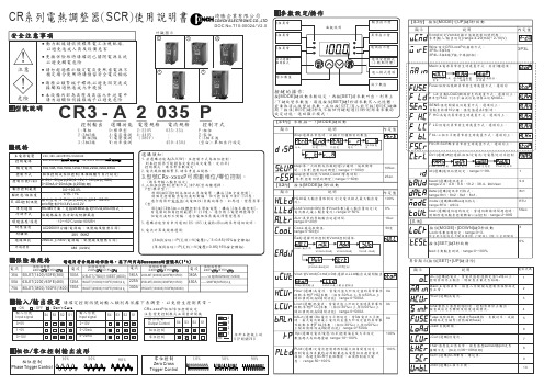
CR SCR 系列電熱調整器()使用說明書琦勝企業有限公司CONCH ELECTRONIC CO.,LTD-3 A 2035P控制輸出 選購功能 電壓規格 電流規格 控制方式1:2:3223:33單相相線 單相線相線D:A:V:W:標準型電流偵測電壓偵測功率偵測2:220V 4:440V (380V)035:35A : :450:450AP:Z:C:3相位零位相半波(空白):單相自行設定220, 380, 440V 15% 50/60HZ±200240VAC 90~240V AC/DC()~(附掛風扇機種)。
無風扇機種35A,50A,75A,100A,125A,150A,225A,300A,450A 相位控制或零位控制單相機種可自行設定()0~5V,1~5V(20K)0~10V,1~10V(100K)0~20mA,4~20mA(250)阻抗阻抗阻抗歐姆類比控制:阻抗對應。
控制0~5V(20K)0.0~100.0%on/off :Hi=3.4V,Lo=2.2VRS-485ModBus RTU ASCII 介面,支援協定或格式。
0.1% / 1%依規格採自然冷卻或附掛風扇AC2000V/1分鐘電源端、訊號端及散熱片間)(2KV 5KHZ20M /500V Ω以上電源端、訊號端及散熱片間)(ABS (UL94V)主電源電壓控制電源額定電流控制方式控制信號VcmdE ADJ .控制訊號串列通訊解析度線性度/冷卻方式環境溫度溼度/耐壓強度耐雜訊絕緣阻抗外殼材質-10~+50C/under 90%RH°0.0~100.0%輸出控制範圍請確定控制訊號的輸入類別再依據下表調整,以免發生控制異常。
位於主控板上的開關DIP S W 1lCRx-xxxxP /相位零位控制設定注意變更控制模式必須重新開機:外觀圖示DOC No.T10-00024/ V2.013425異常顯示按住鍵清除([SET]+[UP])。
三相变压器调节器切换器安装说明书:COOPER POWER SERIES MN800003EN
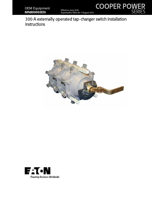
300 A externally operated tap-changer switch installation instructionsDISCLAIMER OF WARRANTIES AND LIMITATION OF LIABILITYThe information, recommendations, descriptions and safety notations in this document are based on Eaton Corporation’s (“Eaton”) experience and judgment and may not cover all contingencies. If further information is required, an Eaton sales office should be consulted. Sale of the product shown in this literature is subject to the terms and conditions outlined in appropriate Eaton selling policies or other contractual agreement between Eaton and the purchaser.THERE ARE NO UNDERSTANDINGS, AGREEMENTS, WARRANTIES, EXPRESSED OR IMPLIED, INCLUDING WARRANTIES OF FITNESS FOR A PARTICULAR PURPOSE OR MERCHANTABILITY, OTHER THAN THOSE SPECIFICALL Y SET OUT IN ANY EXISTING CONTRACT BETWEEN THE PARTIES. ANY SUCH CONTRACT STATES THE ENTIRE OBLIGATION OF EATON. THE CONTENTS OF THIS DOCUMENT SHALL NOT BECOME PART OF OR MODIFY ANY CONTRACT BETWEEN THE PARTIES. In no event will Eaton be responsible to the purchaser or user in contract, in tort (including negligence), strict liability or other-wise for any special, indirect, incidental or consequential damage or loss whatsoever, including but not limited to damage or loss of use of equipment, plant or power system, cost of capital, loss of power, additional expenses in the use of existing power facilities, or claims against the purchaser or user by its customers resulting from the use of the information, recom-mendations and descriptions contained herein. The information contained in this manual is subject to change without notice.ii300 A EXTERNALL Y OPERATED TAP-CHANGER SWITCH INSTALLATION INSTRUCTIONS MN800003EN June 2015ContentsSAFETY INFORMATIONSafety Information (iv)PRODUCT INFORMATIONIntroduction (1)Acceptance and Initial Inspection (1)Handling and Storage (1)Standards (1)INSTALLATION INSTRUCTIONSTorque Requirements (1)Clearances (1)Mechanical Strength (1)Position Indication and Operation (2)Dimensional Information (3)iii 300 A EXTERNALL Y OPERATED TAP-CHANGER SWITCH INSTALLATION INSTRUCTIONS MN800003EN June 2015Eaton meets or exceeds all applicable industry standards relating to product safety in its Cooper Power™ series products. We actively promote safe practices in the use and maintenance of our products through our service literature, instructional training programs, and the continuous efforts of all Eaton employees involved in product design, manufacture, marketing, and service.We strongly urge that you always follow all locally approved safety procedures and safety instructions when working around high voltage lines and equipment, and support our “Safety For Life” mission.iv 300 A EXTERNALL Y OPERATED TAP-CHANGER SWITCH INSTALLATION INSTRUCTIONS MN800003EN June 20151 300 A EXTERNALL Y OPERATED TAP-CHANGER SWITCH INSTALLATION INSTRUCTIONS MN800003EN June 20153 300 A EXTERNALL Y OPERATED TAP-CHANGER SWITCH INSTALLATION INSTRUCTIONS MN800003EN June 2015Eaton1000 Eaton Boulevard Cleveland, OH 44122United StatesEaton’s Cooper Power Systems Division2300 Badger Drive Waukesha, WI 53188United States/cooperpowerseries© 2015 EatonAll Rights ReservedPrinted in USAPublication No. MN800003EN / Rev 0 Supersedes S800601Rev 2Eaton and Cooper Power are valuabletrademarks of Eaton in the U.S. andother countries. You are not permitted touse these trademarks without the priorwritten consent of Eaton.Envirotemp™ and FR3™ are licensedtrademarks of Cargill, Incorporated.For Eaton's Cooper Power series tap-changer switch product informationcall 1-877-277-4636 or visit:/cooperpowerseries.。
电力调整器AYSCR
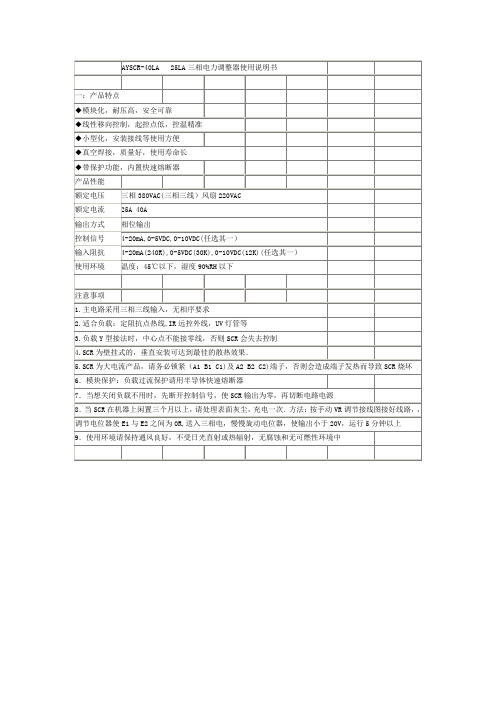
一:产品特点
◆模块化,耐压高,安全可靠
◆化,安装接线等使用方便
◆真空焊接,质量好,使用寿命长
◆带保护功能,内置快速熔断器
产品性能
额定电压
三相380VAC(三相三线)风扇220VAC
额定电流
25A 40A
输出方式
3.负载Y型接法时,中心点不能接零线,否则SCR会失去控制
4.SCR为壁挂式的,垂直安装可达到最佳的散热效果.
5.SCR为大电流产品,请务必锁紧(A1 B1 C1)及A2 B2 C2)端子,否则会造成端子发热而导致SCR烧坏
6.模块保护:负载过流保护请用半导体快速熔断器
7.当想关闭负载不用时,先断开控制信号,使SCR输出为零,再切断电路电源
相位输出
控制信号
4-20mA,0-5VDC,0-10VDC(任选其一)
输入阻抗
4-20mA(240R),0-5VDC(30K),0-10VDC(12K)(任选其一)
使用环境
温度:45℃以下,湿度90%RH以下
注意事项
1.主电路采用三相三线输入,无相序要求
2.适合负载:定阻抗点热线,IR远控外线,UV灯管等
8.当SCR在机器上闲置三个月以上,请处理表面灰尘,充电一次.方法:按手动VR调节接线图接好线路,,
调节电位器使E1与E2之间为0R,送入三相电,慢慢旋动电位器,使输出小于20V,运行5分钟以上
9.使用环境请保持通风良好,不受日光直射或热辐射,无腐蚀和无可燃性环境中
Eaton Power-Sure 700三相电压调节器说明说明书

Eaton Power-Sure 700 (10–500 kVA,three-phase voltage regulator)The Eaton Power-Sure ™ 700 reduces equipment downtime through constant voltage regulation. It is the ideal solution for equipment orfacilities experiencing brownouts and voltage regulation problems. The unique design of the Power-Sure 700 offers a high in-rush current, rapid response and operating advantages over other manufacturers.OverviewThe appropriate transformer tap is automatically activated through a silicon-controlled rectifier (SCR), maintaining a tightly regulated output voltage. Tap changes are initiated within one electrical cycle—switching at zero current crossing to ensure a minimum amount of noise during tap transitions. Seven taps per phase are used for optimal voltage regulation. Also, the Power-Sure 700 is a low output impedance, shielded isolation transformer. As a result of the lowimpedance, load changes do not affect other equipment connecting the system.The Power-Sure 700’s unique design ensures high efficiency at 97% and 1000% in-rush capability. It is equipped with a thermal-magnetic breaker that allows for proper system coordination to prevent nuisance trips.The Power-Sure 700 provides the triple function of isolation, noise attenuation and voltage regulation. The power transformer supplies the first two functions. The third function, voltage regulation, is supplied by the SCRs connected to taps on the power transformer. This sequential tap-changing design eliminates voltage “overshoot” from typical electronic voltage regulators, providing a seamless transition between the required power transformer taps.Power-Sure 700 features•±3% voltage output for a +10/–23% voltage input •Power factor—the Power-Sure 700 is notaffected by load power factor •Total harmonic distortion (THD)—the Power-Sure 700 adds less than 1% added to the output waveform under any dynamic linear loading conditions presented to the line regulator • High efficiency—97%•Wide input frequency range—the Power-Sure 700 operates within a broad input frequency range of 57–63 Hz•Integral manual rotarymaintenance bypass switch standard on 50–500 kVA units and optional on smaller units •Seven taps per phase used to provide optimal voltage regulation•Fail-safe bypass circuit, triple- shielded isolation transformer and overtemperature protection•One-year parts warranty with no startup required •Front-only access required (50–150 kVA units only) allows unit to be installed in tight spacesEaton is a registered trademark.All other trademarks are property of their respective owners.Eaton1000 Eaton Boulevard Cleveland, OH 44122United States © 2021 EatonAll Rights Reserved Printed in USAPublication No. PA158001EN / Z25666November 2021Power-Sure 700 ordering guidelinesA Units with no surge protection option, bypass option or metering option will have blanks in the last three spaces in the catalog number.B Bypass is standard on 50 kVA and larger units and an option on 45 kVA and smaller units.otes: NListings—UL ® Listed, CSA ® Certified, except for 600 V;no UL, CSA on 600 V units. For output distribution, call factory. K factor–rated units available on request.For product support, please contact Eaton’s Technical ResourceCenter (TRC) power quality application engineers at 1-800-809-2772, choose option 5 and then option 2, or *************.For more information, visit /pc .Follow us on social media to get the latest product and support information.。
三相电力调整器(调功器)使用说明书
目录安全及注意事项 (I)第一章H系列三相功率控制器的作用及特点 (1)1.1 作用 (1)1.2 特点 (1)第二章产品信息 (3)2.1 型号定义 (3)2.2 铭牌 (3)2.3 产品规格 (4)2.4 技术参数 (4)2.5 缩略语 (5)第三章安装及配线 (6)3.1 开箱检查 (6)3.2 使用条件 (6)3.3 安装 (7)3.4 电气配线 (7)3.5 基本接线原理图 (8)3.6 端子说明 (9)第四章显示及操作说明 (10)4.1 监控界面显示信息说明 (11)4.2 按键功能说明 (11)4.3 操作举例说明 (12)4.4 菜单 (12)4.5 控制参数A (13)4.6 显示参数B (13)4.7 保护参数C (13)4.7 保护参数C (14)4.8 高级参数D (14)第五章功率控制器功能介绍 (15)5.1 功能介绍 (15)5.2 功能参数表 (22)5.3 参数说明 (23)5.4 举例说明 (32)第六章故障处理及保养维护 (35)6.1 故障处理 (35)6.2 保养维护 (35)第七章通信说明 (37)7.1 通讯数据读写 (37)7.2 协议内容 (37)7.3 总线结构 (37)7.4 通讯帧结构 (38)7.5 MODBUS通讯协议 (38)第八章售后服务 (40)附表一 (41)I安全及注意事项危险:由于没有按要求操作,可能造成设备严重损坏或人员伤亡的场合。
注意:由于没有按要求操作可能造成中等程度伤害或轻伤,或造成物质损失的场合。
本指示对于正在工作的功率控制器非常重要,忽略这些指示可能对您造成身体损害甚至导致死亡。
○1安装控制器应安装在金属等不可燃物上,否则有发生火灾的危险。
不要安装在含有爆炸性气体的环境里,否则有引发火灾的危险。
不要把易燃、易爆物品放在控制器附近,否则有引发爆炸的危险。
不要将螺钉、垫片等金属物掉进控制器内部,否则有引发爆炸和发生火灾的危险。
SCR-LA三相电力调整器说明书

SCR-LA 三相电力调整器-3-三、产品外形、安装尺寸及接线方式注:(单位mm )90%。
温度下限为-30℃,温度上限为+40℃。
七、开箱及检查八、订货须知品合格证 用户在订货时,请注明产品的型号、规格。
如有特殊要求,请与制造商协商。
打开外包装纸盒,检查包装盒内应有使用说明书,产。
5.3 故障排除:原因;检查线路无误后按安装,使用操作说明操作;确属产品本身质量问题的产品,请与当地经销公司或我公司联系。
当产品出现故障后,首先断开电源,然后查找故障六、运输与贮存产品贮存和运输过程中不受到雨雪的侵袭,及挤压,贮存时应放置在空气流通,相对湿度(25℃±5℃)不超过九、公司承诺自产品生产日期起二十四个月内,在客户正常的储运、保养、使用条件下,因产品的制造质量问题而不能正常使用时,提供“三包”服务。
浙江省乐清市柳市镇电器城3单元电话:(86-577)6711 8888 邮编:325604客服热线:400-826-8008传真:(86-577)6711 8000本使用说明书自2013年09月第一版163mm113mmRSTUVW165mm95mm100mmRSTUVWRSTN禁止接零线R S TU V WRST星型接法三角接法控制回路接线说明M最小输出调整BIASMAX最大输出调整内 部 电 源5VDC外部信号输入4mA ~20mA 0V ~10VDC 0V ~5VDC 控制回路接线说明MBIASMAX2K ~10K ΩΩ4mA ~20mA0V ~5VDC0V ~10VDC0V ~5VDC自动控制手动控制指示灯功能说明随着输出电压的增大逐渐变亮随着控制信号的增大逐渐变亮负载端电源接通时亮快速熔断器熔断时亮四、安装、使用操作说明-4-4.1要求(注意三相电接入方向,不能接反)U 、V 、W 接负载,三相负载要平衡,负载可以星型接法和三角接法。
星型接法时,中点禁止接零线。
4.2、控制端分为自动控制和手动控制。
TR-CTH三相调整控制器使用说明
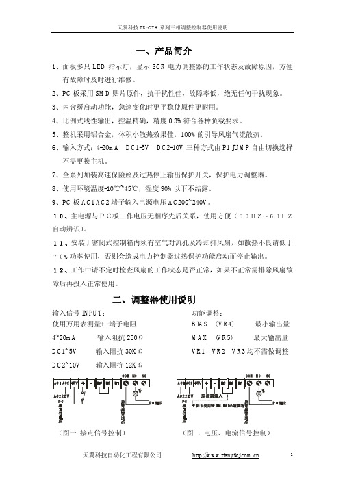
一、产品简介1、面板多只LED指示灯,显示SCR电力调整器的工作状态及故障原因,方便有故障时及时进行维修。
2、PC板采用SMD贴片原件,抗干扰性佳,故障率低,绝无任何干扰现象。
3、内含缓启动功能,急速变化时更平稳使原件更耐用。
4、比例式线性输出,控温精确,精度0.3%符合各种负载要求。
5、整机采用铝合金,体积小散热效果佳,100%的引导风扇气流散热。
6、输入方式:4-20mA DC1-5V DC2-10V三种方式由P1 JUMP自由切换选择不需更换主机。
7、全系列加装高速保险丝及过热停止输出保护开关,保护电力调整器。
8、使用环境温度-10℃~45℃,湿度90%以下不结露。
9、PC板AC1 AC2端子输入电源电压AC200~240V。
10、主电源与PC板工作电压无相序先后关系,使用方便(50HZ~60HZ自动辨识)。
11、安装于密闭式控制箱内须有空气对流孔及冷却排风扇,如散热不良请低于70%功率使用,否则会造成电力控制器过热保护功能启动而停止输出。
12、工作中请不定时检查风扇的工作状态是否正常,如果不正常需排除风扇故障后再投入正常使用。
二、调整器使用说明输入信号INPUT:功能调整:使用万用表测量+ -端子电阻BIAS ( VR4) 最小输出量4~20mA 输入阻抗250ΩMAX (VR5) 最大输出量DC1~5V 输入阻抗30KΩVR1 VR2 VR3均不需做调整DC2~10V 输入阻抗12KΩ(图一接点信号控制)(图二电压、电流信号控制)图三电压、电流、输出由VR调整控制)指示灯功能PWL PC板工作电源指示(主电源通电时亮)IN 温控表输入信号(随温控表输出信号大小变化)OUT SCR输出指示(随SCR输出量大小变化)(零位闪烁)ERR 故障指示(SCR超温)(SCR超温时亮,改善通风效果)FB 故障指示(主电源异常)RUSV(图四CTH系列产品面板示意及指示灯功能说明)注意事项:●建议使用前先用3只电灯泡(功率≥100W )星形接法(共点不接零)做负载调试正常再投入使用。
三相电力调整器使用说明
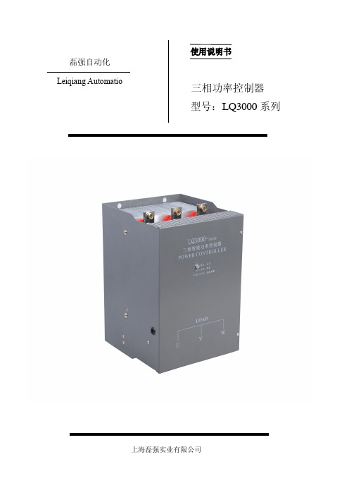
使用说明书磊强自动化Leiqiang Automatio三相功率控制器型号:LQ3000系列上海磊强实业有限公司目录使用注意项.................................11.产品特点.................................22.技术规格...............................2-33.装箱清单.................................44.产品选型及外形尺寸.......................45.订货说明.................................46.电路示意图及输出波形...................5-67.安装及使用须知...........................68.接假负载调试.............................69.接实际负载调试...........................710.控制板常见接线组合......................711.调试中的问题及故障排除................7-812.加热器特性..............................813.不同负载的控制策略......................914.LQ3000控制器的基本特性图示..............915.调功、调压一体化功能...................1016.安装尺寸............................10-111.使用注意事项1. 请不要用手触及电力调整器内部,以防触电。
2. 请不要堵塞散热器上方,不要让杂物进入散热器内部。
否则可能影响机器使用寿命。
3. 在切断电源后一段时间内。
电力调整器的散热器,铜排等有可能处于高温状态,故请不要触摸,以免烫伤。
系列智能型电力调整器LQ3000系列电力调整器是大功率晶闸管模块应用技术的新产品。
三相功率控制器说明书

三相功率控制器说明书三相功率控制器说明书1.引言本文档旨在提供三相功率控制器的详细说明,包括其功能、使用方法、技术规格等。
用户可以根据本文档了解并正确操作三相功率控制器。
2.产品概述本章节介绍三相功率控制器的基本概念和使用范围,包括其作用、适用场景、主要部件等。
3.功能特点本章节详细描述三相功率控制器的功能特点,包括但不限于:●功率调节:可以根据用户需求自由调节功率输出;●过载保护:在负载过大时自动断电保护,以避免设备损坏;●温度控制:能根据设定的温度范围自动调节功率输出;●监控功能:提供实时监测功率输出和温度信息,方便用户进行远程控制和监控。
4.使用方法本章节详细介绍如何正确使用三相功率控制器,包括但不限于以下内容:●供电和电源连接:描述如何正确连接电源,并确保供电正常;●控制界面:详细介绍三相功率控制器的操作界面和控制按钮的功能;●功率调节方法:说明如何根据需要调节功率输出;●温度控制设定:介绍如何设置温度控制范围和温度保护功能;●远程控制:介绍如何通过远程控制方式进行功率调节和监控。
5.技术规格本章节三相功率控制器的主要技术规格和参数,包括但不限于以下内容:●输入电压范围●输出电压范围●最大功率输出●工作温度范围●尺寸和重量等6.附录本章节增加附录部分,包括但不限于以下附件:●产品外观图●电路原理图●控制界面操作指南附件:1.产品外观图2.电路原理图3.控制界面操作指南法律名词及注释:1.功率输出:设备在单位时间内传输或转化的能量。
2.适用场景:三相功率控制器可以应用于工业生产、电力系统调节等领域。
3.远程控制:通过网络或无线传输方式进行远程操作和控制。
4.技术规格:产品的技术要求和参数,包括输入电压、输出电压、最大功率等。
5.负载过大:指负载超过设备承受能力的情况。
6.温度保护:当设备温度超过设定的范围时,自动断电保护。
智能温控器M909 - SCR电力调整器说明书

智能温控器M909 - SCR电力调整器说明书
1、接通电源。
2、按住3秒以上,屏幕上显示OFF,进入关机状态。
3、两个手指同时按住3秒以上,进入1(屏幕左边显示阿拉伯数
字1)程序,显示当前的水温,也就是探头测试到的实际温度。
如果存在测量温度偏差,范围是+/-6℃。
4、按按钮进入2程序,所显示的温度是水泵要启动的温度多少。
出厂设置35℃,如一次进水为冷水时,要将温度调到5℃等进热水后再调回35℃。
5、按按钮进入3程序,显示OFF是低温保护(防结冰)停止,按按钮可以调节低温保护的温度,此功能只有在关机状态下才能启动,出场设置为 OFF。
6、按按钮进入4程序,显示的是水泵开和关的偏差温度,如需调整,按按钮调节,设定0.5℃--3℃,出厂设定0.5℃。
7、按按钮进入5 程序,显示水泵控制工作方式。
按按钮调节:出厂设定工作方法。
工作方式:温控器开机后,水泵开始工作,当达到设定的温度(水泵停止的温度)时,阀门关闭,但水泵一直工作,
201工作方式:水泵的启停与阀门同步,低于水泵停止的温度时,阀门打开水泵运转,达到设定的水泵温度时,阀门关闭水泵停止。
8、按进入6程序,如需恢复出厂设置,长按5秒以上,所有参数恢复出厂置值。
(一般不使用此功能)。
9、按5秒以上进入正常使用,屏幕上显示时间和温度。
长按可以调节水泵要停止的温度(数值闪动时松开)设定范围5℃--99℃数值为单项递增,开至99℃后回到5℃,出厂设置45℃。
10、按选择设置时钟的小时/分钟,再按按钮改变时钟值,当屏幕显示时,说明是在人工控制模式运转。
三相锁定三相开锁电路重启器控制说明书
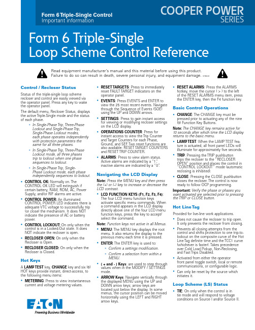
Control / Recloser StatusStatus of the triple-single loop scheme recloser and control are easily viewed via the operator panel. Press any key to wake the operator panel.The default menu, Recloser Status, displays the active Triple-Single mode and the status of each phase.• In Single-Phase Trip, Three-Phase Lockout and Single-Phase Trip, Single-Phase Lockout modes,each phase operates independently with protection parameters the same for all three phases.• In Single-Phase Trip, Three-Phase Lockout mode, all three phases trip to lockout when one phase sequences to lockout.• In Single-Phase Trip, Single-Phase Lockout mode, each phase independently sequences to lockout.• CONTROL OK: Normally on. The CONTROL OK LED will extinguish if certain battery, RAM, ROM, AC, Power Supply, and/or RIF alarms are active.• CONTROL POWER: An illuminatedCONTROL POWER LED indicates there is adequate VTC voltage to successfully trip (or close) the mechanism. It does NOT indicate the presence of AC or battery power.• CONTROL LOCKOUT : On only when the control is in a Locked-Out state. It does NOT indicate the recloser is open.• RECLOSER OPEN: On only when the Recloser is Open.• RECLOSER CLOSED: On only when the Recloser is Closed.Hot KeysA LAMP TEST key, CHANGE key and six (6) HOT keys provide instant, direct-access, to the following menu items:• METERING : Press to view instantaneous current and voltage metering values.• R ESET TAR GETS : Press to immediately reset FAULT TARGET indicators on the operator panel.• EVENTS : Press EVENTS and ENTER to view the 25 most recent events. Navigate through the Sequence of Events (SOE) using the UP and DOWN arrows.• SETTINGS : Press to gain instant access for viewing or modifiying recloser settings on the LCD display.• OPERATIONS COUNTER : Press for instant access to view the Trip Counter and Target Counters for each Phase, Ground, and SEF . Two reset functions are also available: RESET TARGET COUNTERS and RESET TRIP COUNTER.• ALARMS : Press to view alarm status. Active alarms are indicated by a “1”, inactive alarms are indicated by a “0”.Navigating the LCD Displayote:N Press the MENU key and then press the (+) or (–) key to increase or decrease the LCD contrast.• LCD FUNCTION KEYS (F1, F2, F3, F4): The four LCD menu function keysactivate specific menu commands. When a command appears in the LCD display directly above one of the four LCD menu function keys, press the key to accept/select the command.ote:N Function keys not active in all Menus.• MENU : The MENU key displays the root menu. It also returns the display to the previous menu each time it is pressed.• ENTER : The ENTER key is used to:• Confirm a settings modification.• Confirm a selection from within a MENU.• ( + and - ) Keys : are used to step through values when in the MODIFY / SETTINGS mode.• ARROW Keys : Navigate vertically through the displayed MENU using the UP and DOWN arrow keys; arrow keys are located just below the display. In some menus, the cursor position can be moved horizontally using the LEFT and RIGHT arrow keys.• RESET ALARMS : Press the ALARMShotkey, move the cursor ( > ) to the left of the RESET ALARMS menu item, press the ENTER key, then the F4 function key.Basic Control Operations• CHANGE : The CHANGE key must be pressed prior to actuating any of the nine (9) Function Key Buttons.ote:N The CHANGE key remains active for 10 seconds after which time the LCD display returns to the basic menu.• LAMP TEST : When the LAMP TEST fea-ture is actuated, all front panel LEDs will illuminate for approximately five seconds.• TRIP : Pressing the TRIP pushbutton trips the recloser to the “RECLOSER OPEN” position and places the control in “CONTROL LOCKOUT” mode (automatic reclosing is inhibited).• CLOSE : Pressing the CLOSE pushbutton closes the recloser. The control is now ready to follow OCP programming.mportant:I Verify the phase or phases you want activated are selected prior to pressing the TRIP or CLOSE button.Hot Line TagProvided for live-line work applications.• Does not cause the recloser to trip open. It only prevents the recloser from closing.• Prevents all closing attempts from the control and shifts protection to one trip-to-lockout on the composite curve of the Hot Line Tag definite time and the TCC1 curve (whichever is faster). Takes precedence over Cold Load Pickup, Non-Reclosing, and Fast Trips Disabled.• Activated from either the operatorfront panel toggle switch, local or remote communications, or configurable logic.• Can only be reset by the source which initiates it.Loop Scheme (LS) Status• TIE : On only when the control is in tie mode and will respond to voltage conditions on Source I and/or Source II.Read equipment manufacturer’s manual and this material before using this product. Failure to do so can result in death, severe personal injury, and equipment damage.G164.0• SECTIONALIZER: On only when the control is in sectionalizing mode and will respond to voltage conditions on Source I. ote:N When in Sectionalizing mode, the SOURCE II ENABLED function key is not responding to voltage even though it is illuminated.• LS DISABLED: On only when LS is disabled and the control will not respond to the programmed LS loss of voltage parameters.otes:N In the event of loss of AC control power to the control (without battery back-up power), the LS functionality will be disabled when power is restored to the control.In TIE or SECTIONALIZING mode, once voltage is restored, the LS is disabled until locally or remotely enabled.LS functionality must be enabled via the ProView interface software.• A, B, and C PHASE VOLTAGE: When on, these LEDs indicate the phase(s) that initi-ated the LS action.• X, Y, Z PHASE VOLTAGE: When on, these LEDs indicate Source II (load) voltage is present on X, Y, or Z phase(s).• If LS is enabled, at the moment lossof voltage occurs, the LEDs for thephases that lost voltage turn off andthe (TD1) Loss of Voltage TransferTimer begins timing.ote:N The TIE mode will not initiate any loss of voltage timing if both sources are lost. If one source is available, while the TIE mode is timing on loss of voltage, and the available source also loses voltage, the TIE will reset the (TD1) Loss of Voltage Transfer Timer.• If voltage is restored before the volt-age transfer time delay elapses, theLEDs for the phases with restoredvoltage illuminate and the TD1 timerresets.• If voltage is not restored before theVoltage Transfer time delay elapses,the LEDs remain off even if voltagereturns to a particular phase. Thisidentifies the phase that caused theLS to operate.Activating the LS RESET function key resets the LS function and illuminates the voltage LEDs (if voltage is present).• INDICATOR 7, 8: Customizable LEDs that are used with functions programmed through the Idea Workbench TM. The LED indicators do not have active default values. The LEDs are illuminated when the status configured via the Idea Workbench TM is present.Default Function Key ButtonsAlso, refer to “CHANGE” key description.• GND TR IP BLOCKED: Blocks all groundsensing in the control for the active pro-file.• NON-RECLOSING: Places the controlin 1-Shot-to-Lockout mode. When acti-vated, the control will follow the nextprogrammed TCC and a “Control Lockout”will follow the OCP trip event.• SUPERVISORY OFF: When activated,supervisory commands via Contact I/O orany of the communications accessoriesare ignored.• PHASE SELECT BUTTONS: Pressingthe Change button followed by a pressof the A or B or C Phase Select buttonactivates the respective phase; repeatingthe button press sequence a second timedeactivates the phase. The control panelTrip and Close pushbuttons will operateany active phase(s).• 1-Phase T rip / 3-Phase Lockout, mode• 3-Phase T rip / 3-Phase Lockout(ganged) mode• Only 3-Phase manual Trip / Closeoperations are permitted - cannotselect or deselect individual phases.• Pulling the yellow handle down onany phase will open and lockout allthree phases.• CONTROL LOCKOUT, RECLOSEROPEN and RECLOSER CLOSEDcontrol panel LEDs reflect the statusof all three devices.• 1-Phase T rip / 1-Phase Lockout mode• Capable of independent manual Trip /Close operations.• Capable of Independent yellowhandle operation to lockout.• Control panel LEDs for CONTROLLOCKOUT, RECLOSER OPEN andRECLOSER CLOSED blink for mixedrecloser status.• LS RESET: When the LED is illuminated,the LS function has been reset and thecontrol is ready to respond to the nextloss of voltage occurrence. This LEDcannot be de-selected. It will only turn offwhen an LS action occurs.• SOURCE I ENABLED: When the LEDis illuminated, the control is in LS modeand responding to voltage conditions onSource I (source-side Phases A, B, and C).• SOURCE II ENABLED: When the LEDis illuminated, the control is in Tie modeand responding to voltage conditions onSource II (load-side Phases X, Y, and Z).ote:N When the control is in Sectionalizingmode, the SOURCE II ENABLED functionkey may or may not be illuminated(depending on the LS Enable SII setting inthe Loop Scheme Settings Dialog box). It isnot responding to Source II voltage.• OPTION BUTTONS: Three (3) OPTIONbuttons are unassigned by default.ote:N All nine (9) function key buttons canbe customized via the Idea Workbench™.ote:N Non-standard, LS, and Triple-Singlecontrols incorporate different Function Keydefault function configurations.View / Change Settings1. Press the SETTINGS hotkey, the LCDwill display: “Mod/View Settings.”2. Press the ENTER key, the LCD willdisplay « Enter Password «. The defaultpassword is «0» - therefore, if a pass-word has not been assigned just pressthe ENTER key again, otherwise, enteryour password and then press ENTER.ote:N Use the + and – keys to enter apassword. Press-and-hold the key to skipthrough the values faster.Accept / Cancel SettingsChangeFollowing a settings change press theENTER key and then the MENU key. If youmade a change to one or more settingseither:• Accept and USE a changed setting –press the F1 function key.• REVERT to the previously saved setting –press the F2 function key.• Step BACK to the previous dialog – pressthe F4 function key.Eaton1000 Eaton BoulevardCleveland, OH 44122United StatesEaton’s Power Systems Division 2300 Badger Drive Waukesha, WI 53188United States/cooperpowerseries © 2018 EatonAll Rights ReservedPrinted in USAPublication No. MZ280008EN /CSSC-1809-6025KA2048-0722 REV 03Published November 2018Supersedes April 2015 (B280-12061)Follow us on social media to get thelatest product and support information.Eaton is a registered trademark.All other trademarks are propertyof their respective owners.。
三相电压控制器说明书
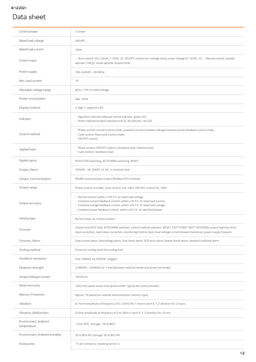
Data sheetControl phase3-phaseRated load voltage440VAC~ Rated load current100AControl input ᆞAuto control: DC4-20mA, 1-5VDC , ON/OFF contact (no-voltage input), pulse voltage (5-12VDC ) ᆞManual control: outside adjuster (10kΩ), inside adjuster (output limit)Power supply100-240VAC~ 50/60Hz Min. load current1AAllowable voltage range90 to 110% of rated voltage Power consumption Max. 32VADisplay method3-digit 7-segment LEDIndicator ᆞOperation indicator/Manual control indicator: green LEDᆞAlarm indicator/output indicator/unit (V, A) indicator: red LEDControl method ᆞPhase control: normal control mode, constant current/constant voltage/constant power feedback control mode ᆞCycle control: fixed cycle control modeᆞON/OFF controlApplied load ᆞPhase control, ON/OFF control: resistance load, inductive load ᆞCycle control: resistance loadDigital inputs RUN/STOP switching, AUTO/MAN switching, RESETOutput_Alarm250VAC~ 3A, 30VDC 3A, 1c resistive loadOutput_Communication RS485 communication output (Modbus RTU method)Output range Phase control: 0 to 98%, Cycle control: 0 to 100%, ON/OFF control: 0%, 100%Output accuracy ᆞNormal control: within ±10% F.S. of rated load voltageᆞConstant current feedback control: within ±3% F.S. of rated load current ᆞConstant voltage feedback control: within ±3% F.S. of rated load voltage ᆞConstant power feedback control: within ±3% F.S. of rated load powerSetting type By front keys, by communicationFunction Output limit (OUT ADJ), AUTO/MAN selection, control method selection, RESET, SOFT START, SOFT UP/DOWN, output high/low limit, input correction, input slope correction, monitoring (control input, load voltage/current/power/resistance, power supply frequencFunction_Alarm Overcurrent alarm, overvoltage alarm, fuse break alarm, SCR error alarm, heater break alarm, heatsink overheat alarm Cooling method Forced air cooling (with the cooling fan)Insulation resistance Over 200MΩ (at 500VDC megger)Dielectric strength2,000VAC~ 50/60Hz for 1 min (between input terminals and power terminals)Output leakage current10mArmsNoise immunity±2kV the square wave noise (pulse width: 1㎲) by the noise simulatorMemory Protection Approx. 10 years(non-volatile semiconductor memory type)Vibration0.75mm amplitude at frequency of 5 o 55Hz (for 1 min) in each X, Y, Z direction for 2 hoursVibration_Malfunction0.5mm amplitude at frequency of 5 to 55Hz in each X, Y, Z direction for 10 minEnvironment_Ambienttemperature-10 to 55℃, storage: -20 to 80℃Environment_Ambient humidity35 to 85% RH, storage: 35 to 85% RHAccessories11-pin connector, isolating barrier: 4ApprovalWeight Approx. 9.7kg(approx. 8.7kg)。
琦勝CR-系列SCR操作手冊说明书

CR-series SCR Operation Manual琦勝企業有限公司CONCH ELECTRONIC CO.,LTD● To prevent electric shock, please make sure that power isturned off before replacing the fuse.● Please connect lines according to National Electrical Code toprevent hazard to human and equipment.!!AttentionDanger● Please do not use beyond the rated current. If the power is unsteady, please retain sufficient current safety reservation● Please lock terminal screws tightly to prevent componentsfrom being burned due to the surge or overheat of contacts● The internal parts of the device are components with high voltage and high temperature. Do not touch any terminal to prevent hazard if it is electrified.Notice of Safety■Model ExplanationCR3- A 2 035 POutput Function Voltage spec.Current spec. Control Mode 1:1φ2: 3φ2W 13: 3φ3Wφ2WD :Standard A: Full function Current detectionV: W: Power detectorFull function(developing)Voltage detection Full function (developing) 2:220V 4: 440V (380V)035:35A : :450:450AP :Phase trigger control Z: Zero cross control C: (Blank ): 3φHalf -wave1φself-setupOptional information:1. If the optional model is with full function (A,V,W) and the control mode is with phase control, the controller can be planned as a constant current (or constant voltage2.The full function model is included the serials communication ( RS-485) which can support ModBus protocal in RTU or ASCII format. Please refer to the communication spec. (Standard type is not included RS-485 and it’s only for display.)3. Current has a wide range of specifications. Please refer to the product specifications4. Single-phase control can be planned to phase / zero control.5. 3 phase control [control mode] with P-type and C-type two options.P-type(standard ):Using 6sets SCR to control each phase’ +/- phase voltage. This is called “3full-wave controlled”. Using 3sets SCR & 3sets diodes to control each phase’ half-circumference phase voltage. This’s called “3half-wave controlled”. It has a wide phase angle control range (0~120 degree). It’s suitable for micro voltage adjustment. Due to line current has DC component, therefore, it’s only suitable for resistive load.5.Current calculation and specifications used(3:、constant power ) control mode. Please refer to the parameter settingsφφIts characteristics is to control the output line current without DC component (average = 0). It’s suitable for inductive (or resistive) load. Such as motors, transformers and so on. The controllable phase angle only have 0~150 degrees control range.φφ)I(AMP) = P(watt) V(voltage 3 0.85 (15% safety reservation (1φ)I(AMP) = P(watt) V(voltage 3 0.85 (15% safety reservation C-type÷ ) ÷ √÷ )÷ ) ÷ √÷ )220, 380, 440V ±15% 50/60HZ200~240VAC (fan included )。
- 1、下载文档前请自行甄别文档内容的完整性,平台不提供额外的编辑、内容补充、找答案等附加服务。
- 2、"仅部分预览"的文档,不可在线预览部分如存在完整性等问题,可反馈申请退款(可完整预览的文档不适用该条件!)。
- 3、如文档侵犯您的权益,请联系客服反馈,我们会尽快为您处理(人工客服工作时间:9:00-18:30)。
CR SCR 系列電熱調整器()使用說明書
琦勝企業有限公司
CONCH ELECTRONIC CO.,LTD
-
3 A 2035P
控制輸出 選購功能 電壓規格 電流規格 控制方式
1:2:3223:33單相相線 單相線相線
D:A:V:W:標準型電流偵測電壓偵測功率偵測
2:220V 4:440V (380V)
035:35A : :
450:450A
P:Z:C:3相位零位相半波
(空白):單相自行設定
220, 380, 440V 15% 50/60HZ
±200240VAC 90~240V AC/DC()
~(附掛風扇機種)。
無風扇機種35A,50A,75A,100A,125A,150A,225A,300A,450A 相位控制或零位控制單相機種可自行設定()
0~5V,1~5V(20K)0~10V,1~10V(100K)0~20mA,4~20mA(250)
阻抗阻抗阻抗歐姆類比控制:阻抗對應。
控制0~5V(20K)0.0~100.0%on/off :Hi=3.4V,Lo=2.2V
RS-485ModBus RTU ASCII 介面,支援協定或格式。
0.1% / 1%依規格採自然冷卻或附掛風扇AC2000V/1分鐘電源端、訊號端及散熱片間)
(2KV 5KHZ
20M /500V Ω以上電源端、訊號端及散熱片間)
(ABS (UL94V)
主電源電壓控制電源
額定電流控制方式控制信號Vcmd
E ADJ .控制訊號串列通訊解析度線性度
/冷卻方式環境溫度溼度/耐壓強度耐雜訊絕緣阻抗
外殼材質
-10~+50C/under 90%RH
°0.0~100.0%
輸出控制範圍請確定控制訊號的輸入類別再依據下表調整,以免發生控制異常。
位於主控板上的開關DIP S W 1l
CRx-xxxxP /相位零位控制設定注意變更控制模式必須重新開機
:外觀圖示
DOC No.T10-00024/ V2.0
1
3
4
2
5
異常顯示按住鍵清除([SET]+[UP])
Vcut=”0V ”,HLtd=90%,LLtd=10%的控制效果STUP=10s (的輸出延遲效果5)
開機或待機超過分鐘RESP=2s 的輸出延遲效果
Vcut=”LLtd ”,HLtd=100%,LLtd=10%的控制效果
● 最小/最大輸出量與的關係
Vcmd(Ccmd)● 緩啟動時間反應時間與輸出的關係
(STUP),(RESP)註:為通訊控制訊號請參考通訊控制Ccmd ,[]
本控制器可以利通訊方式操控的輸出量,以取代的作用。
方法:
. 將接點位址1(通訊控制致能此時顯示器 小數點第一位開始閃爍。
SCR Vcmd (coil)0x011為)2. (reg.4x016)設。
改變暫存器位址數值,輸出隨既改變。
注意在通訊控制模式下,既使不再改變輸出量也必須與控制器保持通訊狀態,例如一直讀取某暫存器或接點位址的數值。
否則控制器會判定為通訊斷線。
若斷線時間超過時間則控制器自動將通訊控制除能以免發生危險。
SCR :
Tout
,通訊功能支援或格式,最多允許連續筆資料讀/寫。
上表的位址為進制。
讀寫方法請參考有關協定相關資料。
RTU ASCII 810ModBus。