GZP中文说明书
拓普gtop人工培养箱说明书

拓普gtop人工培养箱说明书一、产品概述拓普gtop人工培养箱是一种专为实验室和科研机构设计的高精度恒温箱,用于生物学、生物工程、医学、农业等领域的微生物培养和生物反应器的操作。
二、产品特点1. 温度控制精准:拓普gtop人工培养箱采用先进的PID控制技术,温度控制精度高达±0.1℃,可满足各类微生物培养的需求。
2. 多功能操作:拓普gtop人工培养箱具备多种功能,如恒温培养、震荡培养、搅拌培养等,可根据实验需要进行灵活操作。
3. 可编程控制:拓普gtop人工培养箱支持可编程控制,用户可根据实验要求设定温度曲线和时间段,实现自动化操作。
4. 大容量设计:拓普gtop人工培养箱提供多种规格和容量选择,满足不同实验需求,最大容量可达500L。
5. 安全可靠:拓普gtop人工培养箱具备过温保护、断电记忆和故障自诊断等功能,确保实验数据的安全和稳定。
三、使用方法1. 准备工作:将拓普gtop人工培养箱放置于水平台面上,将插头插入电源插座,确保电源正常。
2. 打开仪器:按下电源开关,仪器将开始自检程序,待显示屏显示正常后,即可开始操作。
3. 设定温度:通过操作面板上的温度设定键,将所需温度设定为实验温度。
4. 启动仪器:按下启动键,拓普gtop人工培养箱将开始工作,根据设定的温度进行恒温控制。
5. 监控实验:通过显示屏上的温度显示,可随时监控当前温度,确保实验进行顺利。
6. 结束实验:实验结束后,按下停止键,拓普gtop人工培养箱将停止工作,将温度恢复到室温。
四、注意事项1. 在使用拓普gtop人工培养箱前,请仔细阅读操作手册,并按照要求进行操作。
2. 使用过程中,请勿将水或其他液体溅入仪器内部,以免损坏电路和元件。
3. 请勿将仪器暴露在阳光直射下,以免影响温度控制精度。
4. 定期清洁仪器内部和外部,以保持仪器的正常使用寿命。
5. 如遇到故障或异常情况,请及时联系售后服务中心进行处理。
五、维护保养1. 定期检查拓普gtop人工培养箱的电源线和插头是否损坏,如有损坏应及时更换。
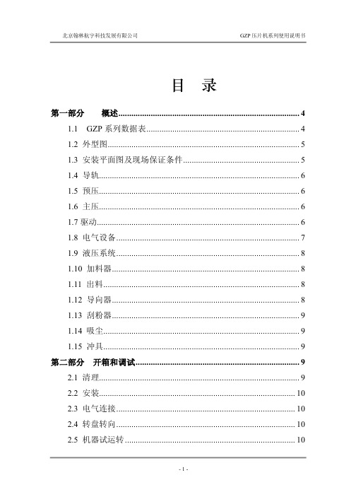
GZP压片机系列使用说明书
-1-
北京翰林航宇科技发展有限公司
GZP 压片机系列使用说明书
.......................................................................... 11 3.1 接通主电源开关 ....................................................................... 11 3.2 机器操作面板安全保护指标.................................................... 11 3.3 工作状态按钮 ........................................................................... 12 3.4 加料调节................................................................................... 13 3.5 压力与片厚 ............................................................................... 13 3.6 预压........................................................................................... 13 3.6 润滑........................................................................................... 14 3.7 平移手轮的调节 ....................................................................... 14 3.8 产量调节................................................................................... 14 3.9 更换模具................................................................................... 15 3.10 更换填充导轨 ......................................................................... 15 3.11 下冲过紧保护控制 .................................................................. 16 3.12 过压控制 ................................................................................. 16 3.13 出料活门控制 ......................................................................... 16 3.14 吹废气阀的调整 ..................................................................... 16 3.15 片重自动调节 ......................................................................... 17 3.16 加料器控制 .............................................................................. 17 3.17 第一次调节建议 ..................................................................... 17
15-恒温箱(光照箱)GZP-250B标准操作规程
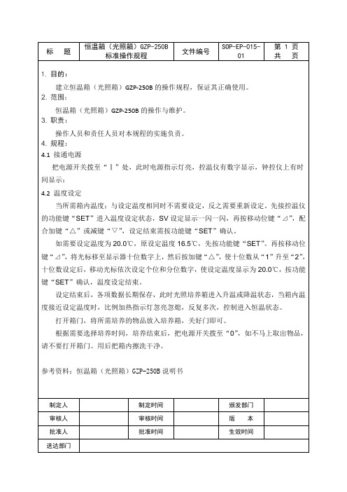
当所需箱内温度;与设定温度相同时不需要设定,反之需要重新设定。先接控温仪的功能键“SET”进入温度设定状态,SV设定显示一闪一闪,再按移动位键“⊿”,配合加键“△”或减键“▽”,设定结束需按功能键“SET”确认。
如需要设定温度为20.0℃,原设定温度16.5℃,先按功能键“SET”。再按移动位键“⊿”,将光标移至显示器十位数字上,然后按加键“△”,使十位数从“1”升至“2”,十位数设定后,移动光标依次设定个位和分位数字,使设定温度显示为20.0℃,按功能键“SET”确认,温度设定结束。
参考资料:恒温箱(光照箱)GZP-250B说明书
制定人
制定时间
颁发部门
审核人
审核时间
版本
批准人
批准时间
生效时间
送达部门
标题
恒温箱(光照箱)GZP-250B标准操作规程
文件编号
SOP-EP-015-01
第1页共页
1.目的:
建立恒温箱(光照箱)GZP-250B的操作规程,保证其正确使用。
2.范围:
恒温箱(光照箱)GZP-250B的操作与维护。
3.职责:
操作人员和责任人员对本规程的实施负责。
4.规程:
4.1接通电源
把电源开关拨至“Ⅰ”处,此时电源指示灯亮,控温仪有数字显示,钟控仪上有时间显示;
设定结束后,各项数据长期保存,此时光照培养箱进入升温或降温状态,当箱内温度接近设定温度时,比例加热指ห้องสมุดไป่ตู้灯忽亮忽熄,反复多次,控制进入恒温状态。
打开箱门,将所需培养的物品放入培养箱,关好门即可。
根据需要选择培养时间,培养结束后,把电源开关拨至“0”,如不马上取出物品,请不要打开箱门。用后把箱内擦洗干净。
高格软件说明书6-生管模组

目录第一章上线准备 (5)第二章生产计划 (6)2-1.生产通知单 (6)2-2.主生产计划(M ASTER P RODUCTION S CHEDULE) (8)2-3.计划工单明细 (14)2-4.返工返修通知单 (20)第三章车间作业 (24)3-1.工单 (24)3-1-1.厂内工单 (24)3-1-2.委外工单 (30)3-2.派工单 (37)3-2-1.派工单 (37)3-2-2.派工变更单 (40)3-3.领料单 (42)3-4.补料单 (47)3-5.用料单 (52)3-6.退料单 (55)3-7.报废单 (60)3-8.入库单 (63)3-9.副产品处理单 (70)3-10.生产看板 (76)3-11.生产日报 (78)3-12.工序移转单 (80)3-13.工单移转单 (87)第四章质量成本 (94)4-1.工成本明细 (94)4-2.产成本分摊 (94)4-3.生产成本重计 (95)第五章生产资源管理 (96)5-1.设备台帐 (96)5-2.设备维护计划 (96)5-3.设备维修记录 (97)5-4.设备运行记录 (98)第六章生产统计分析 (98)6-1.生产进度跟踪 (98)第七章生管参数设定 (101)模块流程图:第一章上线准备准备事项:准备上线前一天之产品库存盘点表做为产品数据新增时之期初数量结算上线前各个客户及厂商之预收、预付、应收、应付款将目前贵公司之所有产品、客户、厂商、业务等基本数据做计算机化前之分析与规划,避免上线一段时间后发现所有使用之编号等作业习惯与流程不符,而须重新登打或修改,浪费不必要的时间流程步骤:1.系统共同参数(维护模块第一章)建立此套帐之公司基本数据及相关设定2.基本数据设定(基本数据第一章)建立公司各产品、往来客户、厂商、员工数据、密码权限..等加以分类及建立详细数据,以便各单据的输入3.库存参数设定(库存模组第十三章)设定库存系统的各项参数,作为后续各作业项目及单据参考的依据值4.期初开帐作业(基本数据第一章)建立客户期初应收款及期初借(出)货数量、厂商期初应付款及期初借(入)货数量、产品期初数量(可分仓) 、产品单位成本..等,使手帐作业与计算机帐数据衔接上,于本系统分析报表中能有效掌握正确数据5.常用单据建立(功能简介第一章)建立公司常用之单据(如:常用之交易产品…等),便利后续各单据中呼叫取用前置动作到此已设定完成,可进行日常单据登录当然在执行时您可跳过某些流程,在您登录数据时再以呼叫方式输入各基本数据及设定各参数数据第二章 生产计划2-1.生产通知单菜单流程:『生管』→『生产计划』→『生产通知单』作业时机:发出销售订单后须通知计划部门,存档后由计划人员进行审核并判断该产品是否分批投产,该功能在销售部与计划部之间起过渡作用栏位说明: 单头部份1) 日 期:记录此生产通知单的日期,预设为系统日期2) 单 号(20 Bytes):显示此张单据之单据号码:此单据编号方式系根据『生管参数设定』中「生管通知单编号」设定格式产生3)覆核:提供覆核功能,未经覆核不可进行下一级运算4) 说 明(200 Bytes):特别事项说明单头部份单身部份【明细】1) 生产确认:提供复选功能;当产品的版本信息比较复杂,需要计划人员或产品部人员确认时,使用该栏位2) 产品代码(20 Bytes):系统根据上层来源单号自动带出,并显示「产品名称」、「版本号」、「产品规格」、「单位」、「单位名称」,不可编修3) 版本号(4 Bytes):提供该产品版本号速查功能,默认为系统根据上层来源单号自动带出之产品版本号,编修后自动回写销售订单4) 订单类型 N(2):自动带出,不可编修。
光培养箱GZP使用说明书

GZP型光培养箱使用说明书一、概述康恒仪器厂家GZP系列光照培养箱是具有制冷、加热、光照度控制的高精度恒温光照模拟试验设备,可用于植物培养,育种试验,细菌、霉菌、微生物的培养、保存,水体分析的BOD测定以及其它用途的恒温试验。
是生物遗传工程、医疗、卫生防疫、药检、农牧水产等科研单位理想的试验设备。
二、结构特点本机箱体采用优质薄板加工而成,表面涂装牢固、美观。
箱门内置内门大璃视窗,如需观察试验物品一目了然。
内胆采用镜面不锈钢薄板,配于活动式搁板加工制成,经久耐用,清洗方便。
设置有三面光照结构和多光谱日光灯管、电加热和制冷系统,确保温度控制稳定准确。
独具的风道设计确保箱内温度波动小、均匀性好,满足培养和实验需求。
控温部分采用以单片机技术,采用PID算法新型智能数显温度调节仪。
用户可根据不同要求选项,周期、照度、分段、定时功能包括中英文显示可选。
大屏液晶显示器界面清晰,操作人性化。
通过操作控制面板的触摸键对温度照度、时段进行设定、调节,达到试验目的。
三、工作原理康恒仪器光照培养箱由位于箱内的传感器,其中温度传感器所感受到的实际温度转换成电信号。
同时可预设的光照强度和电信号,经微电脑来控制加热器、光照灯管数量或制冷压缩机工作,从而达到所需温度、照度控制来达到所需。
四、运行前准备在首次启动设备运行前,请按以下程序操作:1.取出设备内部的搁板等附件。
2.用浸泡过酒精的纱布擦拭箱体内壁进行消毒,然后用干纱布将酒精擦除干净。
3.将搁板根据自己实验要求放入设备内。
五、技术参数1、控温范围:无光照5~50℃、有光照10~50℃;2、温度波动允差:±0.5℃(10℃~40℃设定范围内);3、温度均匀度允差:±1℃(150/250S) 、±1.5℃(350S) (10℃~40℃设定范围内);4、电源电压:交流220V/50Hz;5、输入功率:900W(150L)1000W(250L)1200W(350L);6、工作环境:环境温度10~30℃相对湿度70%以下;7、制冷剂:R134;8、设备类别:I类。
金色焚火 Golden Vap G21 2021年使用手册说明书
Vaporeta GoldenVap G21Manual de Uso2021Características técnicasDescripción y accesoriosÍndiceVaporeta Golden Vap GXManual de usoIntroducciónPuesta en MarchaSomos Golden Vap010*******Asistencia Técnica06El generador de vapor Golden Vap es uno de los sistemas más avanzados y eficaces que existen en el mercado que le permitirá obtener excelentes resultados en limpiezas de toda índole.La fuerza del vapor de agua es suficiente paraconseguir desincrustar cualquier tipo de suciedad y potenciar el brillo de cualquier rincón por inaccesible que parezcaCon una eficacia demostrada clínicamente del 99,9% contra virus, bacterías y gérmenes , Golden Vap es también el aliado perfecto en ladesinfección gracias a la gama de accesoriosespecíficos como la Pistola de desinfección Sanix de todo tipo de espacios, tanto domésticos como profesionales.Súmate a la limpieza ecológica , respetando el medio ambiente ya que nuestro sistema nonecesita de productos químicos nocivos: Tan sólo vapor de agua.Bienvenidos a Golden VapIntroducciónVaporeta Golden Vap GX2021Caratcerísticas técnicasEstas son las prestaciones de tu máquina de vaporTensión220 VFrecuencia50 HzPotencia de caldera1450 WPotencia de plancha800WPotencia máxima total1950WCapacidad útil del deposito1,85 litrosCapacidad total del deposito2,85 litrosTemperatura máxima de caldera140 ºCTemperatura máxima plancha185 ºCInterruptor de encendido Selector de potencia Conector de accesoriosIndicador de presión de agua Potencia de vapor acumulada Tapón de seguridad Tapón de vaciado1.2.3.4.5.6.7.Panel de controlVaporeta Golden Vap G21Descripción y accesoriosCaratcerísticas técnicasEstas son las prestaciones de tu máquina de vaporDesde su salida al mercado en 2002, ha evolucionado hasta llegar al modelo G21 que, además de ser el más moderno y novedoso de todos, ha sabido elevar la elegancia para que destaque en tu hogar.Es un equipo de gran potencia y muy fácil de usar. Es tremendamente manejable gracias a su asa ergonómica pensada para moverlafácilmente por toda la casa.Dispone de un conjunto de accesorios que transforman y adaptan la máquina Golden Vap para cada una de tus necesidades. Llega a todos los rincones de tu hogar fácilmente y desinfecta de una sola pasada. Su potente sistema de vapor, unido a la plancha Black Iron, convertirála Golden Vap en un sistema de planchado profesional pensado para todo tipo de prendas, con especial atención a las más delicadas.Abrir el tapón de seguridadCon una leve presióndesbloquearemos el sistema de seguridad del tapón de nuestra máquina para, posteriormente,desenroscarlo por completo.Puesta en marchaTe explicamos paso a paso como poner en marcha tu VaporetaRellena de agua tu VaporetaPara hacerlo de forma segura,utiliza el biberón suministrado con los accesorios de tu máquinaEnchufa la máquinaEs en este momento cuando debes enchufar tu vaporeta a una fuente de corriente.Enciende la máquinaPresiona los botones de encendido de tu máquina y espera unos minutos.Luz VerdeCuando el piloto verde de tumáquina se encienda significaráque ya está lista para comenzar a ser usada.Conecta la mangueraEs el momento de conectar la manguera o flexo de limpieza al conector frontal de tu máquina.Selecciona la potenciaPara ello utiliza los interruptores provistos en tu manguera de limpieza.Conecta tu accesorioConecta el accesorio que necesites a tu manguera de limpieza.Estamos listosTu vaporeta está ahora preparada para que comiences a disfrutar de las ventajas de la limpieza convapor ¡Buen trabajo010203040506070810En Golden Vap y Asistencia Técnica Lady Vap SL llevamos más de 30 añoscomprometidos con la calidad y seguiremos garantizando las reparaciones de su máquina de vapor de por vida.Confía todas tus reparaciones a un servicio técnico oficial, desde las pequeñas averías hasta el desgaste por el paso del tiempo y de su uso, Asistencia Técnica Lady Vap S.L.conseguirá la mejor solución para su máquina de vapor.Asistencia técnicaReparaciones garantizadas de por vida010203Solicita tu revisiónSolicita una revisión de tu máquina para que siempre esté a puntoSolicita presupuesto¿Tu vaporeta no funcionacorrectamente? Nuestro Servicio Técnico se encargará de valorar su reparación sin com`p romisoReparaciones garantizadasRecambios originales y la mejor atención. En Asistencia Técnica Lady Vap SL garantizamos las reparaciones de tu máquina.Los virus pueden convertirse en un problema, por suerte el VAPOR es capaz de crear un ambiente un 99,9% libre de virus, gérmenes y bacterias sin necesidad de usar productos químicos, gracias al poder el vapor de agua a alta temperatura.Protege tu hogar y a los tuyos con los mejores generadores de vapor del mercado y obtén resultados de limpieza y desinfección inmejorables.En Golden Vap llevamos más de 35 años proporcionándote las mejores soluciones de desinfección y limpieza para tu hogar y/o negocio.Gracias por confiar en el sistema de limpiezaecológico más avanzado del mercadoSomos Golden VapMás de 35 años a tu servicioEl llamado vapor seco a más de 160ºC que genera cualquiera de nuestras máquinas es 100%efectivo contra virus y bacterias sin necesidad de usar agentes agresivos que puedan comprometer el bienestar de los espacios tratados.Esto convierte a nuestras vaporetas en el aliado perfecto para infinidad de sectores sensibles , desde el médico hasta la hostelería pasando por el comercio, transportes y todos aquellos en los que la presencia y tránsito de usuarios y clientes es determinante.ÁR E A S D E A P L I C A C I ÓN R E C O M E N D A D AProtege a tus clientes y usuarios con los mejores generadores de vapor del mercado y obtén resultados de limpieza y desinfección inmejorables sin necesidad de usar productos químicos y disminuyendo así el impacto medioambiental .B E A P R OSistema VIRUCIDA efectivo contra COVID19 229Ebasado en el test UNI EN ISO 16777: 2018915716700 - 645679993Paseo de la Castellana 179 - 1º izq 28046 | Madrid。
象贸易股份有限公司GPPW中文使用手册
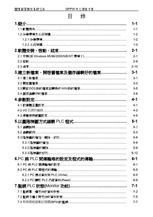
象貿易股份有限公司GPPW中文使用手冊目錄1.簡介…………………………………………………………….… 1-11.1軟體特色…………………………………………………………………………….. 1-11.2作業環境及系統架構….………………………………………………………. 1-21.2.1作業環境………………………………………………………………………. 1-21.2.2系統架構… …………………………………………………………………... 1-32.軟體安裝、啟動、結束………………………………………….. 2-12.1安裝(在Windows 95/98/2000/ME/NT環境下)…………………………………. 2-1 2.2啟動………………………………………………………………………………….. 2-92.3結束………………………………………………………………………………….. 2-103.建立新檔案、開啟舊檔案及儲存編輯好的檔案………………. 3-13.1建立新檔案………………………………………………………………………….. 3-13.2開啟舊檔案………………………………………………………………………….. 3-33.3開啟DOS版的檔案並轉換成WIN版的檔案……..……………………………….. 3-53.4儲存編輯好的檔案………………………………………………………………….. 3-84.參數設定…………………………………………………………. 4-14.1記憶體容量設定…………………………………………………………………….. 4-14.2 I/O位置的編排………….………………………………………………………….. 4-34.3停電保持範圍設定………………………………………………………………….. 4-55.以畫階梯圖方式編輯PLC程式………………………………… 5-15.1編輯說明…………………………………………………………………………….. 5-15.2編輯範例……….…..…………………………………….………………………….. 5-35.3階梯圖的增加、刪除、修改……..…………………….………………………….. 5-65.3.1階梯圖的增加…………………………………………………………………. 5-65.3.2階梯圖的刪除…………………………………………………………………. 5-95.3.3階梯圖的修改…………………………………………………………………. 5-126.PC與PLC間傳輸埠的設定及程式的傳輸.…………………… 6-16.1 PC與PLC間傳輸埠的設定………………..…….……………………………….. 6-16.2 PC與PLC間程式的傳輸.……………………..………………………………….. 6-56.2.1 PC傳送資料到PLC (Write)…………………………………………………. 6-56.2.2 PC讀取PLC內部資料(Read)………………………………………………. 6-87.監視PLC狀態(Monitor功能)…………………..………………. 7-17.1監視單一種元件的資料狀態….………………..………………………………….. 7-2 7.2監視多種不同元件的資料狀態……………..……………..……………………….. 7-57.3特殊模組緩衝記憶體(BFM)的監視…..………..………………………………….. 7-78.更改元件號碼………………..…………………..………………. 8-1 8.1 Replace device(大範圍元件號碼更改)………..………………………………….. 8-18.2 Change open/close contact (大範圍元件a、b接點互換)……………………….. 8-39.密碼設定及清除PLC記憶體…………………..………………. 9-1 9.1 設定密碼………………………………………..………………………………….. 9-1 9.2 刪除PLC內部密碼………………………………………..……………………….. 9-39.3 清除PLC記憶體…………………………………………..……………………….. 9-510.其他功能介紹…………………………………..………………. 10-1 10.1更改計時器(T)或計數器(C)的設定值………..…………………………….…….. 10-1 10.2顯示所有已使用的元件…..……………………………..………………….…….. 10-3 10.3遙控PLC的CPU模組RUN/STOP….………………..……………………….. 10-5 10.4 PLC CPU模組的自我診斷……………………………………………………….. 10-7 10.5 註解編輯……………………………………………………………….………….. 10-910.5.1編寫註解…………………………………………………………………..…. 10-910.5.2 註解顯示設定………………………………………………………………. 10-1010.5.3 顯示註解……………………………………………………………………. 10-12 附錄一.功能選擇列及圖示工具列功能說明………………..……. 附錄-11. 功能選擇列各項功能說明…………………………………………………………… 附錄-11.1 Project 專案…………………………………………………………………. 附錄-11.2 Edit 編輯……………………….……………………………………………. 附錄-31.3 Find/Replace尋找/更改….…………………………………………………. 附錄-51.4 Convert 轉換…………………….…………………………………………. 附錄-61.5 View 檢視……………………………………………………………………. 附錄-71.6 Online 連線…………………………………………………………………. 附錄-81.7 Diagnostics 自我診斷………………………………………………………. 附錄-91.8 Tools 工具…………..………………………………………………………. 附錄-101.9 Windows 視窗……………..…………………………………………………. 附錄-111.10 Help 說明………………………………….……..………..………………. 附錄-122. 圖示工具列各項功能說明…………………………………………………………… 附錄-132.1 Standard 標準工具…………………………………..………………………. 附錄-132.2 Project data list 檔案總管工具……………..………………………………. 附錄-132.3 LD symbol 階梯圖符號………………..……………………………………. 附錄-142.4 Program 程式圖示工具………………..……………………………………. 附錄-152.5 Comment 註解圖示工具……………………………………………………. 附錄-15象貿易股份有限公司GPPW中文使用手冊6. PC與PLC間傳輸埠的設定及程式的傳輸6.1 PC與PLC間傳輸埠的設定PC與PLC的傳送介面有很多種,在此我們僅介紹PC透過串列埠(Serial Port)與PLC的CPU Port傳輸。
全自动硅片装片机使用说明书

GZP -2A 全自动硅片装片机使用说明书中国电子科技集团公司第二研究所二〇〇九年十二月1.概述1.1 主要用途及适用范围将方形硅片装入到25片篮具中以供下一工艺使用。
1.2 产品特点GZP-2A全自动硅片装片机主要由设备本体、篮具升降系统、上料位升降机构、上料位、皮带传送结构、控制面板、晶片分取系统构成。
本产品型号组成:“GZP”代表硅片装片,“2”代表设备有2个工位, “A”代表设备有两组吸盘。
执行标准Q/AH318-1998《产品型号的命名》。
1.3 品种、规格全自动硅片装片机、GZP-2A1.4 使用环境条件a) 环境温度:15℃-35℃b) 相对湿度:<60%、无凝露d)周围环境:无腐蚀性气体1.5 工作条件产品工作条件为单相三线制电源,并有压缩空气源。
1.6 对环境及能源的影响本产品对环境无污染。
1.7 产品所执行标准的编号GB 191-1990 包装储运图示标志GB 4793.1-1995 测量控制和试验室用电气设备的安全要求 Q/AH 117-2002 产品标牌Q/AH 318-1998产品型号的命名2.结构特征及工艺流程2.1结构特征GZP-2A全自动硅片装片机主要由设备本体、篮具升降系统、上料位升降机构、上料位、皮带传送结构、控制面板、晶片分取系统构成(图1)。
图 1z上料位:可调节,能兼容两种规格的硅片;z上料位升降机构:采用伺服电机精确控制升降运动;z分片结构:气嘴分别位于硅片两侧,吹气方向可调;在吸盘真空开始后略微下降上料台,提供足够空间让粘连硅片分开;z吸盘:吸盘采用4个吸盘结构,吸取更稳定;z缓冲结构:气缸带动缓冲结构做升降运动,避免硅片与传送带发生撞击;z传送带: 传送带选取对硅片无损伤和无污染的材料制成;z篮具托盘:采用定位销限位,更容易、精确地达到精度要求;z篮具上升机构:采用伺服电机精确控制升降运动;z导向定位:设备采用导向机构,保证硅片移动的准确性; 2.2工艺流程工艺流程示意图如图2。
1934349-1 Z-PACK TinMan高速板端连接器系列产品说明书
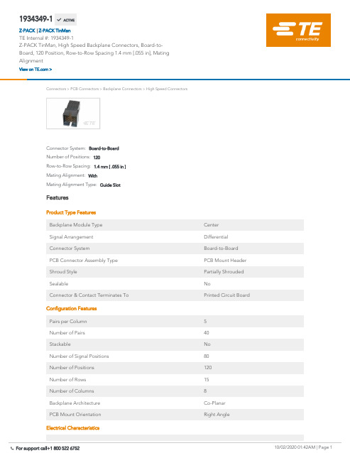
1934349-1Z-PACK TinMan, High Speed Backplane Connectors, Board-to-Board, 120 Position,Row-to-Row Spacing 1.4 mm [.055 in], Mating AlignmentConnectors>PCB Connectors>Backplane Connectors>High Speed ConnectorsMating Alignment Type:Guide SlotMating Alignment:WithRow-to-Row Spacing: 1.4 mm [ .055 in ]Number of Positions:120Connector System:Board-to-BoardFeaturesProduct Type FeaturesBackplane Module Type CenterSignal Arrangement DifferentialConnector System Board-to-BoardPCB Connector Assembly Type PCB Mount HeaderShroud Style Partially ShroudedSealable NoConnector & Contact Terminates To Printed Circuit BoardConfiguration FeaturesPairs per Column5Number of Pairs40Stackable NoNumber of Signal Positions80Number of Positions120Number of Rows15Number of Columns8Backplane Architecture Co-PlanarPCB Mount Orientation Right AngleElectrical Characteristics1934349-1 ACTIVEZ-PACKTE Internal #:1934349-1Z-PACK TinMan, High Speed Backplane Connectors, Board-to-Board, 120 Position, Row-to-Row Spacing 1.4 mm [.055 in], MatingAlignmentView on >Z-PACK TinMan|UL Voltage Rating250 VACImpedance100 ΩOperating Voltage250 VACSignal CharacteristicsDifferential Impedance100 ΩNumber of Differential Pairs per Column5Data Rate10 Gb/sBody FeaturesShield Material Phosphor Bronze Contact FeaturesContact Mating Area Length 6 mm[.236 in]PCB Contact Termination Area Plating Material Thickness.5 µm[20 µin]Contact Type PinContact Mating Area Plating Material GoldPCB Contact Termination Area Plating Material Finish MatteContact Shape & Form Rectangular PostPCB Contact Termination Area Plating Material TinContact Base Material Phosphor Bronze Contact Current Rating (Max).5 ATermination FeaturesTermination Post & Tail Length 2.2 mm[.087 in] Termination Method to Printed Circuit Board Through Hole - Press-Fit Mechanical AttachmentMating Retention WithoutPCB Mount Alignment WithoutGuide Hardware WithoutPCB Mount Retention WithPCB Mount Retention Type Action/Compliant Tail Mating Alignment WithMating Alignment Type Guide Slot Connector Mounting Type Board Mount Housing FeaturesNumber of Shrouded Sides2End Wall Location OpenHousing Material LCP (Liquid Crystal Polymer)Housing Color BlackCenterline (Pitch) 1.9 mm[.075 in]DimensionsConnector Length15.35 mmConnector Height24.4 mmConnector Width36.61 mmPCB Thickness (Recommended) 1.57 mm[.062 in]PCB Hole Diameter.47 mmRow-to-Row Spacing 1.4 mm[.055 in]Usage ConditionsOperating Temperature Range-65 – 90 °C[-85 – 194 °F]Operation/ApplicationCircuit Application SignalIndustry StandardsUL Rating RecognizedUL File Number E28476Agency/Standard ULUL Flammability Rating UL 94V-0Packaging FeaturesPackaging Method Box & Tube, TubeProduct ComplianceFor compliance documentation, visit the product page on >EU RoHS Directive 2011/65/EU CompliantEU ELV Directive 2000/53/EC CompliantChina RoHS 2 Directive MIIT Order No 32, 2016No Restricted Materials Above ThresholdEU REACH Regulation (EC) No. 1907/2006Current ECHA Candidate List: JUN 2020(209)Candidate List Declared Against: JUN 2012(84)Does not contain REACH SVHCDoes not contain REACH SVHCHalogen Content Not Yet Reviewed for halogen content Solder Process CapabilityNot applicable for solder process capabilityProduct Compliance DisclaimerThis information is provided based on reasonable inquiry of our suppliers and represents our current actual knowledge based on the information they provided. This information is subject to change. The part numbers that TE has identified as EU RoHS compliant have a maximum concentration of 0.1% by weight in homogenous materials for lead, hexavalent chromium, mercury, PBB, PBDE, DBP, BBP, DEHP, DIBP, and 0.01% for cadmium, or qualify for an exemption to these limits as defined in the Annexes of Directive 2011/65/EU (RoHS2). Finished electrical and electronic equipment products will be CE marked as required by Directive 2011/65/EU. Components may not be CE marked. Additionally, the part numbers that TE has identified as EU ELV compliant have a maximum concentration of 0.1% by weight in homogenous materials for lead, hexavalent chromium, and mercury, and 0.01% for cadmium, or qualify for an exemption to these limits as defined in the Annexes of Directive 2000/53/EC (ELV). Regarding the REACH Regulation, the information TE provides on SVHC in articles for this part number is based on the latest European Chemicals Agency (ECHA) ‘Guidance onrequirements for substances in articles’ posted at this URL: https://echa.europa.eu/guidance-documents/guidance-on-reachTE Model / Part #6643222-1SLIMLINE,ICCON,PIN,ASSYTE Model / Part #6643220-1SLIMLINE,ICCON,SKT,ASSYTE Model / Part #1658020-1MSB0.80PL30ASY040FL,-,10,-TYTE Model / Part #1934347-1TinMan R/A Header Assy 5x16 OpenHigh Speed Backplane Connectors(64)Board-to-Board Headers & Receptacles(1)TE Model / Part #1934218-1Tin Man Recept Assy 5 pair 8 ColumnCompatible PartsAlso in the Series Z-PACK TinManCustomers Also BoughtTE Model / Part #6368062-12X4 OFFSET STK MJ,SHLD,W/LEDTE Model / Part #6-1469373-8ATCA GUIDE MODULE RA FEMALETE Model / Part #3-582119-9TEST PROBE REC130 TRI-MT WHT GPBRTE Model / Part #1934335-1TinMan Header Assy 3x6 openTE Model / Part #636120-12MM-HM,4ROW LEV 1 ACTN PINTE Model / Part #1744428-83.96 EP HDR ASSY 8P R/A, GWDocumentsProduct DrawingsTinMan R/A Header Assy 5x8 OpenEnglish CAD Files3D PDF3DCustomer View ModelENG_CVM_CVM_1934349-1_B.2d_dxf.zipEnglishCustomer View ModelENG_CVM_CVM_1934349-1_B.3d_igs.zipEnglishCustomer View ModelENG_CVM_CVM_1934349-1_B.3d_stp.zipEnglishBy downloading the CAD file I accept and agree to the of use.Terms and Conditions Datasheets & Catalog PagesHigh Speed Backplane Connectors catalog - Z-PACK TinMan High Speed, High Density Backplane ConnectorEnglishProduct SpecificationsApplication SpecificationEnglish。
2GIG-PAD1-345 无线遥控器参考手册说明书
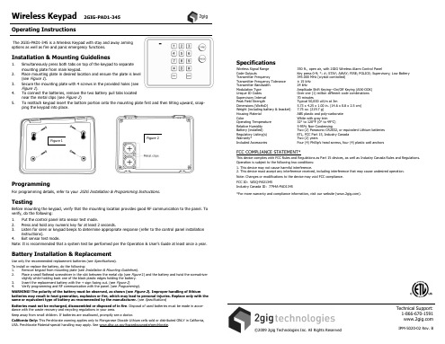
FCC COMPLIANCE STATEMENT*
This device complies with FCC Rules and Regulations as Part 15 devices, as well as Industry Canada Rules and Regulations. Operation is subject to the following two conditions: 1. This device may not cause harmful interference. 2. This device must accept any interference received, including interference that may cause undesired operation. Note: Changes or modifications to the device may void FCC compliance. FCC ID: WDQ-PAD1345 Industry Canada ID: 7794A-PAD1345
Battery Installation & Replacement
Use only the recommended replacement batteries (see Specifications).
To install or replace the battery, do the following: 1. Remove keypad from mounting plate (see Installation & Mounting Guidelines). 2. Place a small flathead screwdriver in the slot between the metal clip (see Figure 2) and the battery and twist the screwdriver
Sennheiser 螺纹螺栓 GZG 1029 和 GZG 1029-1 产品说明说明书
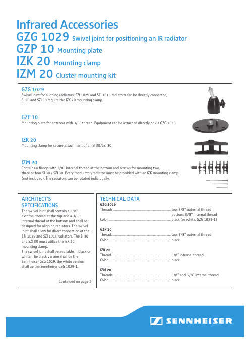
ARCHITECT ’S SPECIFICATIONSThe swivel joint shall contain a 3/8“ external thread at the top and a 3/8“ internal thread at the bottom and shall be designed for aligning radiators. The swivel joint shall allow for direct connection of the SZI 1029 and SZI 1015 radiators. The SI 30 and SZI 30 must utilize the IZK 20 mounting clamp.The swivel joint shall be available in black or white. The black version shall be the Sennheiser GZG 1029, the white version shall be the Sennheiser GZG 1029-1.Continued on page 2GZG 1029Swivel joint for aligning radiators. SZI 1029 and SZI 1015 radiators can be directly connected; SI 30 and SZI 30 require the IZK 20 mounting clamp.GZP 10Mounting plate for antenna with 3/8“ thread. Equipment can be attached directly or via GZG 1029.IZK 20Mounting clamp for secure attachment of an SI 30/SZI 30.IZM 20Contains a flange with 3/8” internal thread at the bottom and screws for mounting two,three or four SI 30 / SZI 30. Every modulator/radiator must be provided with an IZK mounting clamp (not included). The radiators can be rotated individually.TECHNICAL DATAGZG 1029Threads ...................................................................... t op: 3/8“ external threadbottom: 3/8“ internal threadColor ...........................................................................black (or white, GZG 1029-1)GZP 10Thread........................................................................top: 3/8“ external threadColor ...........................................................................blackIZK 20Thread........................................................................3/8“ internal thread Color ...........................................................................blackIZM 20Threads ......................................................................3/8“ and 5/8“ internal thread Color ...........................................................................blackInfrared AccessoriesGZG 1029 Swivel joint for positioning an IR radiator GZP 10 Mounting plate IZK 20 Mounting clampIZM 20 Cluster mounting kitPRODUCT VARIANTSGZG 1029 (black) Art.No: 03226 GZG 1029-1 (white) Art.No: 03227 GZP 10 Art.No: 003193 IZK 20 Art.No: 003560 IZM 20 Art.No: 003561Sennheiser electronic GmbH & Co. KG Am Labor 1, 30900 Wedemark, Germany 1 0 / 1 2 S e n n h e i s e r i s a r e g i s t e r e d t r a d e m a r k o f S e n n h e i s e r e l e c t r o n i c G m b H & C o . K G . w w w . s e n n h e i s e r . c o m . C o p y r i g h t ©1 0 / 2 0 1 2 . A l l r i g h t s r e s e r v e d . E r r o r s a n d o m i s s i o n s e x c e p t e d .Infrared AccessoriesGZG 1029 Swivel joint for positioning an IR radiator,GZP 10 Mounting plate, IZK 20 Mounting clamp, IZM 20 Cluster mounting kit ARCHITECT’SSPECIFICATIONSThe mounting plate shall provide a 3/8“ external thread for antenna attachment. The equipment shall be mountable directly to the mounting plate or via the GZG 1029 swivel joint. The color of the mountingplate shall be black. The mounting plate shall be the Sennheiser GZP 10.The mounting clamp shall provide a 3/8“ internal thread for wall or ceiling mounting an SI 30/SZI 30. The color of the mounting clamp shall be black. The mounting clamp shall be the Sennheiser IZK 20.The cluster mounting kit shall contain a 3/8“ and 5/8“ internal thread for mounting two to four SI 30/SZI 30. Every modulator/ radiator must utilize one IZK 20 mounting clamp (not included). The color of the mounting kit shall be black. The cluster mounting kit shall be the Sennheiser IZM 20.Contact your local Service Partner:。
压片机GZP40系列使用维修说明书
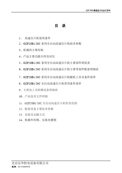
目录1、高速压片机使用条件2、GZP28B1/28C系列全自动高速压片机技术参数3、机器的主要结构4、产品主要功能介绍及对比5、GZP28B1/28C系列全自动高速压片机主要部件材质表6、GZP28B1/28C系列全自动高速压片机主要零部件配套明细表7、GZP28B1/28C系列全自动高速压片机随机工具及备件清单8、GZP28B1/28C全自动高速压片机常用备件清单9、主要加工及检测设备明细表10、产品技术文件明细11、GZP28B1/28C全自动高速压片机供货范围12、配套设备主要技术参数13、包装及运输方式14、机器外形图、安装布置图GZP28B1/28C全自动高速压片机1、高速压片机使用条件1.1工作环境:符合GMP规范的相关要求1.2压制物料要求1.2.1 颗粒要求颗粒大小范围:12-60目,具有良好的可压性及流动性;合成药淀粉片:颗粒均匀、不潮湿、颗粒中细粉(60目以上)所占比例不超过三分之一;中药颗粒:全浸膏、半浸膏和生粉颗粒,要求不能潮湿,具有一定的流动性。
1.2.2 干粉粉未适用于粉未直接压片,所压制粉未应具有一定的可压性及流动性。
1.3 可压制片型:可压制普通圆片、大形片、异形片、特异形片、单双面刻字片、卡通片等。
1.4 电源要求380V,50Hz,三相五线制,N线和PE线不能相互干扰。
2、GZP系列全自动高速压片机技术参数(GZP28B1/28C)3、机器的主要结构3.1 机器结构组成机器主体结构由底板、前后立架、前后框架、蜗轮箱、机座、冲盘组合、上支撑块及控制柜等部分组成。
(见图1)底板、前后立架,前后框架,机座和蜗轮箱通过螺栓连接组成一个固定的框架,构成压片机的基础,蜗轮箱固定在机座上。
以蜗轮箱基础,将压片机的各功能部件:如填充和计量机构、下冲保护装置、下预压轮、主压轮调节机构、出片导轨、充填导轨、下冲保护导轨和模具拆卸挡块等部件安装在机座上。
支撑块通过左右立柱拉杆和穿过主轴中心的拉杆将冲盘和上导轨盘与机座相连,形成稳固的三立柱框架结构,该结构具有极强的抗弯曲和抗扭转能力,以满足高速压片机高速运转时的承载要求。
GZP500中文说明书
GZP500系列旋转式压片机使用说明书中华人民共和国上海天和制药机械有限公司目录1 .用途说明和适用范围 (1)2.主要技术参数 (1)3.工作原理与主要结构………………………………………………1-24.安装调整和使用……………………………………………………3-65.常见的故障与排除方法……………………………………………6-76.电器操作方法………………………………………………………7-97.机器的润滑 (9)8.机器的保养 (10)9.滚动轴承目录及安装位置 (10)开机前,必须仔细阅读本说明书,说明书内不推荐的行为均可能引起机器的异常或人身安全。
本机执行标准:JB20020-2004《旋转式压片机》1. 用途说明和适用范围1.1 本机是一种自动旋转、连续压片的机器。
它主要用于制药工业的片剂制造,特别适用于化工、食品、电子等工业部门压制大片难成形物料。
1.2 本机适用于能压制成形(本机压力范围内)的,而且含粉量(100目以上)不超过10%的颗粒状原料的压制。
1.3 本机适用于压制5~25毫米的圆形和刻字片剂。
1.4 本机不适用于半固体、潮湿颗粒、低溶点易潮原料和无颗粒的粉末压制。
2.3. 工作原理与主要结构3.1 转台结构(图一)转台是本机工作的主要执行件。
由上、下轴承组件、主轴、转台等主要另件构成。
转台的圆周上均布冲模,转台与主轴间由平键传递扭矩。
主轴支承在圆锥滚子轴承上,由蜗轮副传动,平键连接,转动主轴,使转台旋转工作。
3.2 轨导机构(图二)轨导由上轨导和下轨导组成的圆柱凸轮和平面凸轮,是上、下冲杆运动的轨迹。
上轨导由拉上轨、压下轨、上冲上平行轨、上冲润滑轨等多块轨导组成。
它们分别紧固在上轨导盘上。
下轨导由出片轨、下冲下行轨和充填轨、过桥轨、充填轨组成。
它们分别安装在下轨导座上。
下行轨的出口处有一块装卸轨,供装拆下冲杆用。
3.3. 充填调节装置(图三)充填调节用于调节片剂的重量。
它由一对蜗轮付和一对螺旋付组成,蜗杆传动蜗轮,带动螺杆上下运动,从而使安装在螺杆轴上的充填轨上升或下降,达到充填量的变化。
GoStix Plus 元粒花了方舟 afinar文档说明书
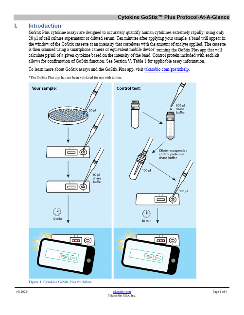
I. IntroductionGoStix Plus cytokine assays are designed to accurately quantify human cytokines extremely rapidly, using only20 µl of cell culture supernatant or diluted serum. Ten minutes after applying your sample, a band will appear inthe window of the GoStix cassette at an intensity that correlates with the amount of analyte applied. The cassette is then scanned using a smartphone camera or equivalent mobile device* running the GoStix Plus app that will calculate pg/ml of a given cytokine based on the intensity of the band. Control protein included with each kit allows for confirmation of GoStix function. See Section V, Table 1 for applicable assay information.To learn more about GoStix assays and the GoStix Plus app, visit /gostixhelp.*The GoStix Plus app has not been validated for use with tablets.Figure 1. Cytokine GoStix Plus workflow.II. Before You BeginWhen you first use the app, you will need to connect your device to the internet so that the standard curves for available lots of cytokine GoStix Plus products can be downloaded into the app. The app uses the standard curve to calculate pg/ml of cytokine.Contact your network administrator if you experience issues downloading standard curve data or if the app cannot find your lot number upon initial entry. If the problem persists, please contact technical support.III. Testing Your Sample1.Download the GoStix Plus app from the Apple App Store (iOS) or Google Play (Android) onto yoursmartphone or equivalent mobile device.NOTE: The GoStix Plus app has not been validated for use with tablets.2.Open the app on your mobile device and enter a valid email address to begin. This email address is youraccount and the destination to send assay results from the mobile device (see Step 15).3.Click [Start].4.Enter the lot number by scanning the QR code on the foil pouch containing the GoStix cassette. (Press the QRcode icon to activate the scanner.) The lot number can also be entered manually.NOTE: Do not use the QR code on the outside of the box; it is not recognized by the app software.5.Enter the number of tests to be scanned (1–8 tests). The equivalent number of sample name windows willappear below.6.Enter the sample names into the windows and the related dilutions. Click [Start].NOTES:Assay range: Each cytokine GoStix Plus assay is designed to accurately quantify a given cytokine within adesignated range (specified in the corresponding Certificate of Analysis for the assay). Similar to ELISAmethods, first-time users are advised to consider running the assay on several sample dilutions in addition totesting an undiluted sample to ensure that they obtain a valid reading within the designated range of the assay-specific standard curve.Serum samples: We recommend diluting serum samples by at least 1:10 with PBS or media to minimizeassay variability and decrease viscosity. The GoStix Plus app includes a dropdown menu for enteringdilutions as high as 1:100,000.Samples with expected high levels of analyte: We recommend performing additional dilutions using eitherPBS or media to reduce the analyte percentages in the solution.7.Dilute 20 µl of your sample (after Step 6) with 80 µl of chase buffer.8.Add the entire 100 µl of sample and chase buffer to the sample well (S) of the GoStix cassette. Allow thechase buffer front to appear in the cassette window.9.Press [Start] to activate the timer on the app.10.Allow the lateral flow test to run for the full 10 minutes. A test band (T) will start to appear within 5 minutesand reach maximum intensity at 10 minutes if your sample contains sufficient levels of analyte. The controlband (C) will always appear when the test is functioning properly.NOTE: The test will not give consistent results if the full development time is not observed. A warningwithin the app will appear if the [Skip] button is pressed before the 10 minutes have expired.For accurate results, it is important that the intensity of the test band is less than that of the control band. Thecloser this ratio is to 1, the closer the sample is to exceeding the standard curve. If a reading exceeds thestandard curve, the app will return a Gostix Value (GV) of “Off Scale” and an error message willappear recommending that the sample be diluted. If no analyte is detected in the sample, the app willreturn a GV of 0 pg/ml.11.After 10 minutes, the app will alert you to take a picture of the cassette. Proper alignment and focal length forimaging is achieved by using the outline of the cassette in the scanning window. Your sample name willappear below the outline of the cassette.Once proper alignment is achieved, the outline will turn green and the cassette will automatically be scanned.NOTES:•Depending on the device used,it may be necessary to tap the device screen in order to focus prior to scanning.•Avoid creating shadows when imaging the GoStix cassette.12.Once all samples are read, the results will be displayed in the Result detail window. If desired, add notes foreach sample in the “Notes” section of the Result detail window, at this time.13.Press [Done]when finished to save each data entry.14.If you wish to rescan a sample, repeat steps 3, 4, and 5, skip the protocol page(s) and timer (press [Start],[Skip], and then [Yes]) to proceed. Do not exceed 20 minutes of total development time (i.e., rescanning must take place within 10 minutes of initial timer expiration).NOTE: Lateral flow tests can continue to develop after the initial 10-min development time, such thatvariation in development time can contribute to read variability. If replicate reads from the same test aredesired, we recommend timing the acquisition of the images as close to each other as possible.Typical coefficients of variation (%CV) for replicate reads of the same test vs. replicate tests of the samesample are <10% and <15%, respectively.15.If desired, individual results from the Result history page (accessed from the main menu) can be emailed orsent via SMS by pressing the [Share] button at the bottom of each overview page. Accumulated results canalso be downloaded as a single batch to your device using the [Download all] button on the Result historypage.Please visit /gostixhelp for further instructions on how to access results downloaded to yourdevice.IV. Calibrating GoStix Results with Other Assays Using a Reference Standard GoStix assay results can be calibrated to international standards using conversion factors specific to each assay.These conversion factors are provided in the corresponding assay’s Certificate of Analysis.Cytokine GoStix™ Plus Protocol-At-A-Glance V.Testing the Cytokine Control Protein1.Control protein for each assay is supplied in a dried format. To resuspend, add 500µl of chase buffer andvortex.2.Dilute the control protein for your specific assay as indicated in Table 1 (below).NOTE: The control protein is provided to confirm the proper function of the lateral flow test. Followinginitial resuspension in 500 µl of chase buffer, the control protein is too highly concentrated to yield a readingwithin the range of the standard curve referenced in the app and will cause the app to return a GV of “OffScale”. Further dilution is required to ensure that the control reading falls within the standard curve.3.Apply 100 µl of the diluted control to the sample well (S) of the GoStix cassette.4. A control band (C) and test band (T) will appear in 10 minutes.5.For future control tests, the reconstituted control protein can be stored at 4o C for up to 1 week. For extendedstorage, prepare aliquots to store at –20o C and avoid repeated freeze-thaw cycles.Table 1. Recommended control protein dilutions.Assay Catalog Nos. Dilution (control suspension +chase buffer)IFN-γ GoStix Plus631285, 631286 1:8 (25 μl + 175 μl)IL-2 GoStix Plus631283, 631284 1:40 (5 μl + 195 μl)IL-6 GoStix Plus6312991:40 (5 μl + 195 μl)TNF-α GoStix Plus631287, 6312881:32 (6.25 μl + 193.75 μl)Contact UsCustomer Service/Ordering Technical Supporttel: 800.662.2566 (toll-free) tel: 800.662.2566 (toll-free)fax: 800.424.1350 (toll-free) fax: 800.424.1350 (toll-free)web: /service web: /supporte-mail: **********************e-mail: *******************************Notice to PurchaserOur products are to be used for Research Use Only. They may not be used for any other purpose, including, but not limited to, use in humans, therapeutic or diagnostic use, or commercial use of any kind. Our products may not be transferred to third parties, resold, modified for resale, or used to manufacture commercial products or to provide a service to third parties without our prior written approval.Your use of this product is also subject to compliance with any applicable licensing requirements described on the product’s web page at . It is your responsibility to review, understand and adhere to any restrictions imposed by such statements.©2020 Takara Bio Inc. All Rights Reserved.All trademarks are the property of Takara Bio Inc. or its affiliate(s) in the U.S. and/or other countries or their respective owners. Certain trademarks may not be registered in all jurisdictions. Additional product, intellectual property, and restricted use information is available at .This document has been reviewed and approved by the Quality Department.。
谷夫道Pungo双Z轴控制系统用户操作说明书

谷夫道Pungo双Z轴控制系统版本号V1.0操作手册安全须知本节叙述有关CNC装置使用的安全预防措施。
用户必须遵守这些预防措施以保证配置有CNC的机床的安全操作,这是非常重要的。
注意有些预防措施只与一些特定的功能相关,因此对某些CNC装置是不可用的。
操作者还必须遵守由机床厂商提供的说明书中指明的与机床有关的安全预防措施。
操作者必须在完全熟悉本说明书以及由制造厂商提供的相关说明书的内容后,才能操作机床或编制程来控制机床。
一般的警告和注意1.零件加工前,一定要首先检查机床的正常运行。
加工前,一定要通过连续仿真保证机床正确工作。
例如利用单段执行,进给倍率,或手轮引导等,且在机床上不装工件和刀具时检查机床的正确运行。
如果未能确认机床动作的正确性,机床可能出现错误动作,有可能损坏工件、机床或伤害用户。
2.操作机床之前,请仔细地检查输入的数据。
如果使用了不正确的数据,机床可能错误动作,有可能引起工件的损坏、机床本身的损坏或使用户受伤。
3.确保指定的进给速度与想要进行的机床操作相适应。
通常,每一台机床都有最大许可进给速度。
合适的进给速度根据不用的操作而变化。
请参阅机床厂提供的说明书来确定最大的进给速度。
如果没有按正确的速度进行操作,机床有可能发生错误动作,从而引起工件或机床本身的损坏,甚至伤及用户。
4.当使用刀具补偿功能时,请仔细检查补偿方向和补偿量。
使用不正确的指定数据操作机床,机床可能发生错误动作,从而引起工件或机床本身的损坏,甚至伤及用户。
C内部的参数都是机床厂设置的,通常不需要修改,当必须修改参数的时候,请确保改动参数之前对参数的功能有深入全面的了解。
如果不能对参数进行正确的设置,有可能引起机床的错误动作,可能损坏工件、机床本身或伤害用户。
6.在软件启动以后,请不要随意触碰键盘上的键。
键盘上很多键被指定为软件的快捷键,按下这些键,可能使机床处于某种状态。
7.本说明书叙述的某些功能,对特定机床实际上并不适用。
Great Plains GPRO Fuel Transfer Pump说明书
PRO35-115 & PRO35-115RD115/230 VoltPRO35-115AD Automatic Diesel Nozzle PRO35-115MD Manual Diesel Nozzle922108-01D11/14To the owner...Congratulations on receiving your GPRO™ Fuel Transfer Pump. We are pleased to provide you with a system designed to give you maximum reliability and efficiency.Your fuel pump is designed, tested, and approved for use with gasoline, kerosene, and diesel fuel. Please take all due pre-cautions when handling these flammable liquids. Your safety is important to us.Also, to assure the longest possible service life, it is important that you follow the operation and maintenance procedures outlined in this manual. We are proud to provide you with a quality product and dedicated support. Together with your conscientious use, we are sure that you will obtain years of safe, dependable service.Victor Lukic, President Great Plains Industries, Inc.TABLE OF CONTENTSGeneral Information ....................................................2Safety Instructions ......................................................2Installation ..................................................................2Operation ....................................................................4Troubleshooting ..........................................................5Illustrated Parts Drawing ............................................6Specifications .............................................................7Parts and Service .......................................................7Warranty .......................................................See InsertSAVE THESE INSTRUCTIONSOWNER'S MANUALYour pump is designed for use only with thin viscosity petroleum fuels such as gasoline (up to 15% alcohol blends such as E15), diesel fuel (up to 20% biodiesel blends such as B20) and kerosene. Do not use this pump for dispensing any fluids other than those for which it was designed. Using the pump with other fuels can damage components and void the warranty. Use of alcohol blends above 10% (E10) and biodiesel blends above 5% (B5) have not been reviewed by UL.Model ComponentsPRO35-115AD: Includes pump, hose and automatic diesel nozzle.PRO35-115MD: Includes pump, hose and manual diesel nozzle.PRO35-115PO: Includes pump only.PRO35-115RD: Includes dedicated pump only for remote dispensing systems.PRO35-115PO/XTS: Includes pump only and compo-nents to assemble to unit before use.NOTE: Suffixes MD, AD, PO and PO/XTS are for order-ing purposes only. Constructions described above are covered as alternate constructions under the Part No.PRO35 UL Listing.How to Use This ManualThe purpose of this manual is to assist you in installing, operating and maintaining your GPRO™ pump. If you need additional assistance, contact your GPRO dealer or the Great Plains Industries Customer Service Department.The following safety alert symbols are used inthis manual. Obey all safety messages that followthis symbol to avoid possible injury or death.DANGER indicates animminently hazardoussituation which, if not avoid-ed, will result in death orserious injury.WA R N I N G i n d i c a t e sa potentially hazardoussituation which, if not avoid-ed, could result in death orserious injury.C A U T I O N i n d i c a t e sa potentially hazardoussituation which, if not avoid-ed, may result in minor ormoderate injury.CAUTION CAUTION used withoutthe safety alert symbolindicates a potentiallyhazardous situation which,if not avoided, may result inproperty damage.There are inherent dangers wherever flammable fuel andAC electrical sources are in close proximity.Static electricity as a source of sparking is always aconcern and requires extreme care in the installation andoperation of your entire fuel transfer system.Additional components such as meters, automatic nozzlesand filters must be listed for use with fuel transfer systems.The flow of fuel through a hose and nozzle can generatestatic electrical charges and dangerous sparking canresult in fire or explosion. Hoses and nozzles must beelectrically conductive and bonded to ground.It is your responsibility to:• Know and follow applicable national, state and localsafety codes pertaining to installing and operatingelectrical equipment for use with flammable liquids.• Know and follow all safety precautions when handlingpetroleum fuels.•Ensure that all equipment operators have access toadequate instructions concerning safe operating andmaintenance procedures.INSTALLATIONMechanical ConnectionsCoverplates protect the operator from moving parts. Neveroperate the pump without coverplates in place. Never applyelectric power to the pump without coverplates in place.Always disconnect power before repairing or servicing.WARNINGAll threaded fuel connections must be sealed with threadtape or a pipe thread sealing compound approved foruse with petroleum fuels.Your pump must be mounted on a vented tank. If thetank is not vented, contact your GPRO distributor forthe correct vent cap.This pump has a built-in check valve to keep the pumpprimed. No additional check valve is required on suctionpipes shorter than 15 ft. (4.6 m). Make sure any checkvalves or foot valves used are equipped with properpressure relief valves.Your pump is designed to mount directly to a standard2 in. female tank fitting. For the suction pipe, a 1¼ in.galvanized steel pipe cut to length and threaded on oneend may be used. Suction pipe should extend to within3 inches of tank bottom. Apply thread tape to the suc-tion pipe thread and securely tighten the suction pipe tothe tank adapter. Once suction pipe is attached to tankadapter, insert suction pipe into tank and tighten tankadapter to tank fitting.2922108-01D PRO35-115 / PRO35-115RDInstall Nozzle Hanger(Not applicable to pumps with -RD suffix) Attention: The nozzle hanger for your pump was removedbefore shipping to protect against damage.To reinstall the nozzle hanger follow the steps below. 1. Remove the two ¼"-20 x ½" bolts and the two flatwashers from the switch coverplate.2. Place the two bolts through the nozzle cover and thenplace the two flat washers on the bolts. The washers are used as spacers to set the nozzle hanger away from the switch coverplate.3. Align the bolts with the two threaded holes on theswitch coverplate; thread the bolts into the holes.Torque bolts to 45-60 in/lb (Figure 1).Switch Locking LeverAttention: The PRO35-115RD remote dispenser pump incorporates an external switch locking lever that locks the pump switch in the “ON” position. The pump is typically shut off using the remote dispensing device “ON-OFF” mechanism.Electrical ConnectionsElectrical wiring and connections must be made only by a licensed electrician in accordance with national, state and local electrical codes regarding Class I, Division 1, Group D locations. Other codes may apply.Thread for the conduit connection at the pump electrical box is ½ in. FNPT.A standard 15-amp breaker is recommended.This pump is equipped with an auxiliary AC accessorylead. The third wire (red) is to be used to energize a control circuit that operates a device such as a signal light or a solenoid operated valve. Maximum amp draw on the control circuit is 1 amp. If you do not need this feature, ensure that the wire is insulated and enclosed within the electrical cavity of the pump.Wiring Details1. Remove electrical coverplate (Figure 2). Install con-duit and cable from switchbox to pump electrical box.Wiring must be in accordance with Class I, Division 1 requirements in the applicable national electrical code.2. Attach ground wire using the green ground screw lo-cated inside the electrical box (Figure 3). Connect the power cable to the pump wiring per the wiring diagram located inside the electrical coverplate. Secure with wire nuts.3. Position wires inside the electrical box. Replaceelectrical coverplate with all seven screws and tighten securely.3922108-01D PRO35-115 / PRO35-115RDTo dispense fuel (for pumps with nozzlehanger):1. Remove the nozzle from the holder. Turn the pumpon by pulling the switch lever down.2. Insert the nozzle into the receiving tank and squeezethe handle to dispense fuel.3. After dispensing fuel, push the switch lever up to turnthe pump off and return the nozzle to the holder. Thenozzle may be locked in place to prevent unauthorizeduse.The pump contains an automatic bypass valve to preventpressure buildup when the pump is on but the nozzleis closed. Do not leave the pump on for more than 10minutes with the nozzle closed.Never leave the pump running without fluid. Dry runningcan damage the pump components.The pump has a duty cycle of 30 minutes ON and 30minutes OFF. Do not overheat. Allow the motor to coolthe same length of time it was in operation.The fuel strainer and check valve assembly should becleaned on a regular basis or if low flowrate is noticed.If the pump becomes too hot, an internal temperature-limiting device will automatically shut the motor off andprevent operation until it cools.4922108-01D PRO35-115 / PRO35-115RDSYMPTOM PROBABLE CAUSE CORRECTIVE ACTIONA. MOTOR DOESNOT RUN 1. No electrical power to pump Check breaker, switchbox and wiring.2. Auxiliary temperature-limitingdevice trippedAllow motor to cool. Auxiliary temperature-limiting device will automati-cally reset.3. Rotor or vanes jammed Remove coverplate and check for damage or obstruction.B. MOTOR RUNSBUT DOES NOTPUMP FLUID 1. Tank level low Add fuel to tank.2. Clogged filter assembly Remove and clean filter assembly.3. Clogged or broken suction pipe Remove pump and clear suction pipe, replace as needed.4. Broken shaft key Replace shaft key. Check rotor or vanes for obstructionC. PUMP FAILS TOPRIME 1. Air leak in system Check for air leaks at all joints2. Bypass valve stuck open Remove bypass valve and clean or replace as needed.3. Check valve stuck open Remove check valve and clean or replace as needed.4. Rotor or vanes worn Check rotor and vanes for excessive wear.D. LOW FLOWRATE 1. Low voltage Check incoming line voltage.2. Clogged filter assembly Clean filter assembly.3. Air leak in system Check for air leaks at all joints.4. Bypass valve stuck open Remove bypass valve and clean or replace as needed.5. Rotor or vanes worn Check rotor and vanes for excessive wear.6. Outlet is blocked Check all accessories for blockage.7. Clogged or broken suction pipe Remove pump and clear suction pipe, replace as needed.D. MOTOR STALLSWHEN NOZZLE ISCLOSED 1. Bypass valve stuck closed Remove bypass valve and clean or replace as needed.2. Rotor or vanes worn Check rotor and vanes for excessive wear.3. Low voltage Check incoming line voltage.B. FUEL LEAKAGE 1. Threaded joint loose Check and reseal threaded joint.2. Insufficient bolt torque Retighten bolts.3. Lost or damaged O-rings Check O-rings for damage. Replace as needed.4. Shaft seal worn or damaged Fuel leaking from drain hole indicates shaft seal needs to be replaced.D. MOTOROVERHEATS 1. Pumping high viscosity fluids Pump only low viscosity fluids2. Clogged filter assembly Clean filter assembly.3. Clogged or broken suction pipe Remove pump and clear suction pipe, replace as needed.5922108-01D PRO35-115 / PRO35-115RD6922108-01D PRO35-115 / PRO35-115RDKits and Accessories133502-1 Vane Kit – O-Ring, 2 in. vanes, shaft key 133503-1Shaft Seal Kit – Retaining ring, shaft seal, spacer washer133503-05 Shaft Seal Kit, Extreme Temperature Series 133504-1Seal Kit121013-503 Check Valve Assembly Kit504500-04 Spares, Base Assembly, 2" Inlet 504500-02 Kit, Switch, PRO35-115 / PRO95-230504500-03 Vacuum Breaker Kit7922108-01D PRO35-115 / PRO35-115RDThe PRO35 series fuel pump is designed to safely trans-fer low viscosity petroleum fuels such as gasoline (up to 15% alcohol blends such as E15), diesel fuel (up to 20% biodiesel blends such as B20) and kerosene. The pump is designed for permanent mounting on vented storage tanks, either in-ground or above-ground. RAINPROOF for outdoor use. Use of alcohol blends above 10% (E10) and biodiesel blends above 5% (B5) have not been reviewed by UL.Performance Pump Rate: Up to 35 GPM (132 LPM) Duty Cycle: 30 minutes ON, 30 minutes OFF Dry Prime:15 ft. (4.6 m) maximumDischarge Lift: 10 ft. (3 m) maximum Operating Temperature-20° F to +125° F (-29° C to +52° C)XTS Operating Temperature Extreme T emperature Series pumps are capableof operation down to -40° F. A ny pump operation below -20° F has not been evaluated by UL.Bypass Pressure25 PSI ElectricalInput: Factory set at 115 VAC, 60 Hz. Optional to set at 230 VAC, 60 Hz.Conduit:½ in. FNPTCurrent Draw: 9.8 amps at full load (at 115 VAC, 60Hz)Motor:¾ HP, 1725 RPM induction type provided with an internal auxiliary temperature-limiting device Mechanical Connections Bung: 2 in. MNPT Inlet: 1 ¼ in. FNPT Outlet: 1 in. FNPTAccessories Hose: 1 in. NPT x 1 in. x 18 ft. (5.5m) Buna-N electrically conductiveNozzle: 1 in. NPT manual or 1 in. NPT auto-matic dieselSecurity: Nozzle can be padlocked Ship WeightPRO35-115PO 67.0 lbs (30.4 kg) PRO35-115MD 78.0 lbs (35.4 kg) PRO35-115AD 80.2 lbs (36.4 kg) PRO35-115RD65.1 lbs (29.5 kg)SAVE THESE INSTRUCTIONSIn order to preserve the UL Listing for pump safety, return the entire pump to the factory for repair or replacement. For products serviced outside the factory, the UL name-plates must be defaced to indicate that the equipment may no longer meet the requirements for UL Listing. This does not apply to products serviced outside the factory under the UL program for Rebuilt Motors for Use in Hazardous Locations.For warranty consideration, parts, or other service infor-mation, please contact your local distributor. If you need further assistance, contact the Great Plains Industries Customer Service Department in Wichita, Kansas, during normal business hours.800-835-0113 or 316-686-7361To obtain prompt, efficient service, always be prepared with the following information:1. The model number of your pump.2. The manufacturing date code of your pump.For the PRO35 series, the date code is located on the motor nameplate.For warranty work, always be prepared with your original sales slip or other evidence of purchase date.Please contact Great Plains Industries before returning any pump. It may be possible to diagnose the trouble and find a solution with a telephone call. Great Plains Industries can also inform you of any special requirements you will need to follow for shipping.POWER OPERATED PUMP FOR PETROLEUMPRODUCTSMOTOR FORHAZARDOUS LOCATIONSCertified Motor© 2014 Great Plains Industries, Inc. All Rights Reserved. Made in U.S.A. and GPRO TM are trademarks,and the electric gear pump design is a registered trademark of Great Plains Industries, Inc.11/14922108-01D。
杰弗逊自由工业 G-Power 自主吸取中心力 pump说明书
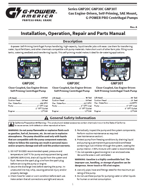
Series GNP20C GNP30C GNP30TGas Engine-Driven, Self-Priming, SAE Mount,G-POWER PRO Centrifugal PumpsRev. AInstallation, Operation, Repair and Parts ManualG-power Self-Priming Centrifugal Pumps handle big, high-capacity, liquid transfer jobs with ease. Use them for transferring water, liquid fertilizers, and other chemicals compatible with pump materials. Make short work of other farm jobs: filling nurse tanks, watering seedbeds and transferring liquids. This self-priming model makes it ideal for de-watering applications.GNP20CClose-Coupled, Gas Engine-Driven Self-Priming Centrifugal PumpGNP30CClose-Coupled, Gas Engine-Driven Self-Priming Centrifugal PumpGNP30TClose-Coupled, Gas Engine-Driven Self-Priming Centrifugal Trash PumpCalifornia Proposition 65 Warning – This product and related accessories contain chemicals known to the State of California to cause cancer, birth defects or other reproductive harm.WARNING: Do not pump flammable or explosive fluids such as gasoline, fuel oil, kerosene, etc. Do not use in explosive atmospheres. The pump should be used only with liquids that are compatible with the pump component materials. Failure to follow this warning can result in personal injury and/or property damage and will void the product warranty. 1. DO NOT EXCEED recommended speed, pressure andtemperature (140° F) for pump and equipment being used.2. BEFORE SERVICING, drain all liquids from the system and flush. Remove the spark plug wire from the spark plug before servicing the pump or engine.3. Secure the discharge lines before starting the pump. An unsecured line may whip, causing personal injury and/or property damage.4. Check hose for weak or worn condition before each use. Make certain that all connections are tight and secure.5. Periodically inspect the pump and the system components. Perform routine maintenance as required (see Maintenance section).6. Protect pump from freezing conditions by draining liquid and pumping a permanent-type automobile antifreeze containing a rust inhibitor through the system, coating the pump interior. A 50% mixture with water is recommended.7. Do not operate a gasoline engine in an enclosed area. Be sure the area is well ventilated.WARNING: Gasoline is a highly combustible fuel. The improper use, handling, or storage of gasoline can be dangerous. Never touch or fill a hot engine.8. Use only pipe, hose and fittings rated for the maximum psi rating of the pump.9. Do not use these pumps for pumping water or other liquids for human or animal consumption..............................................1 0 8 f e e tSuction Head: ..................................... 26 feet Max. Waterflow .................................158 GPM Ports: ........................................... 2" NPT Inlet2" NPT OutletEngine: ............................................... LCT208............................................. 89 f e e tSuction Head: ..................................... 26 feet Max. Waterflow .................................227 GPM Ports: ........................................... 3" NPT Inlet3" NPT OutletEngine: ............................................... LCT208....................................................99 f e e tSuction Head: ............................................23 feet Max. Waterflow ........................................110GPM Ports: ................................................. 3" NPT Inlet3" NPT OutletEngine: .................................................. ... LCT208g -PowerA m e r i caPlease Note: It is illegal to ship or transport any hazardous chemicals without United States Environmental Protection Agency Licensing.1. Always drain and flush pumps before servicing or disassembling for any reason.2. Before returning unit for repair, drain out all liquids and flush unit with neutralizing liquid. Then, drain the pump. Attach a tag or include a written notice certifying that this has been done.3. Never store pumps containing a hazardous chemical.Prior to MountingBefore setting up the pump for operation, check to see that the motor and pump turn freely by hand. If it cannot be turned over by pulling on the recoil starter, open casing to check for obstructions lodged in pump.Selecting the Suction LineTo get full capacity of the pump, the suction line should be the same size as the pump suction port. If suction hose is longer than approximately 6 feet, use next size larger hose. The suction line must be free of air leaks. All joints andconnections of the suction line must be tightened securely so that no additional air may enter the suction side through aloose connection. Use a good grade of suction hose that will not collapse.Basket StrainerThe basket strainer supplied with this pump is to be used when transferring solutions that may contain debris and solids which could become lodged in the pump or damage the impeller. Because of the high flow capacity of thispump, unknown debris could be siphoned offthe bottom of the tank. Install the strainer on the suction side of the pump whenever possible to avoid pump damage.Preparations before Starting the Engine1. Fuel: Check fuel level in tank. Do no over fill tank. Use fresh, clean automotive fuel. Note: DO NOT FILL FUEL TANK WHEN ENGINE IS RUNNING.2. Engine Oil: Before checking or refilling with engine oil, make sure the engine is stopped and placed on a stable, level surface. Use oil recommended for ambient air temperatures that the engine will be running at. See chart below. Change oil according to manufacturer’srecommendation. (Once after the first 20 hours and every 100 hours thereafter.)2. Priming Water: IMPORTANT: PUMP MUST NOT BE RUN DRY. On self-priming pumps, only the chamber needs to be filled with liquid. The pump must not run unless the priming chamber is completely filled with liquid because there is a danger of damaging the mechanical seal, which depends on the liquid for its lubrication.Self-priming models can be primed by removing the filler cap, located at the top of the pump where the discharge line is mounted to the pump, and filling the priming chamber with liquid. The priming chamber will fill to the level of the inlet port. After use, the priming chamber should be flushedand drained to avoid chemical corrosion and damage from freezing. Drain by removing the lower drain plug located at the bottom of the casing.Starting the PumpIMPORTANT: Before starting engine, be sure the primingchamber is filled with liquid and the discharge hose is secure. 1. Turn engine switch located by recoil starter to ON position.2. Turn the fuel cock to ON.3. Push the throttle lever to a slightly open position.4. Operation of choke lever.When engine is cold:In cold weather, start engine with choke in fully closed position.In warm weather, start engine with choke in half- closed position.When engine is warm:Start engine with choke in fully open position.5. Start engine by pulling recoil starter out quickly and forcefully. Repeat pulling until the engine starts.Operation of the Pump1. Idle the engine for 3 to 5 minutes to warm it up.2. Open the throttle lever to the upper zone after engine has warmed up.3. Once the pump has primed, you will note a load on the engine; adjust RPMs to proper speed for your pumping application.Air TemperatureSingle-grade Oil85° F #40W 60° F #30W 32° F #20W(Operation and Maintenance Continued)Stopping the Pump1. Stop pump for a short time:Run engine throttled all the way down (fully to the right). Turn engine switch to OFF position.2. Stopping pump for storage:Turn fuel cock to OFF position instead of turning the engine switch off.Let the engine idle for 2 to 3 minutes until fuel in carburetor is depleted and engine stops. If a valve is installed on the discharge hose, you may run pump with valve closed during this procedure.Note: Pump must not be run dry. Make sure there is water in the priming chamber.Storage1. Drain pump. Flush Pump after Use.One of the most common causes for faulty pump performance is gumming or corrosion inside the pump. Flush the pump and entire system with a solution that willchemically neutralize the liquid pumped. Mix according to the manufacturer’s directions. This will dissolve most residues remaining in the pump, leaving the inside of the pump clean and ready for use.To Prevent Corrosion:After cleaning the pump as directed above, flush it with permanent-type automotive antifreeze (Prestone, Zerex, etc.) containing a rust inhibitor. Use a 50% solution; half antifreeze and half water, or fill the pump with FLUID FILM and drain it. A protective coating of FLUID FILM will remain on the inner pump surfaces. Save the excess FLUID FILM for the next application. Plug ports to keep out air during storage. For short periods of idleness, noncorrosive liquids may be left in the pump, BUT AIR MUST BE KEPT OUT. Plug the ports or seal port connections.2. Drain all the fuel from the fuel tank, fuel lines, and filter.3. Store pump in a clean, dry environmentAlways flush pump with water or neutralizing agent before servicing.Pump Housing DisassemblyFor this pump model, seal replacement requires that the pump be fully removed from the engine. Observe carefully the disassembly process, (orientation and order of part assembly) to ensure an easy assembly process.1. Pull spark plug wire off spark plug for safety considerations. Remove the four bolts holding the casing to the casing cover and frame using a 14mm socket wrench. Tap pump casing on the discharge port with a rubber hammer, if necessary, to break it loose from the casing cover. Check inside pump casing. If badly eroded or damaged, pump casing should be replaced. Remove O-rings from casing cover and volute.2. Remove volute and inspect for wear. Replace if eroded.3. Remove impeller by turning the bolt counterclockwise usinga socket and impact wrench. If an impact wrench is not available, it may be necessary to hold the crankshaft from turning. To keep the crankshaft from turning during disassembly, remove the three bolts holding the recoil starter using a 10mm socket wrench. Then, using a pipe wrench or another tool, hold the starter hub and turn theimpeller bolt off. Using a pry bar on each side of impeller closest to the crankshaft slide impeller off. Use caution during the removal so to not damage the impeller. Remove the key from crankshaft keyway. Look for shims that may be present between the impeller and shaft. This shim isfor obtaining the proper clearance between the impeller and volute. Be careful not to damage the starter hub while gripping it with the wrench.4. Between the impeller and casing cover is the mechanical seal. On the backside of the impeller is the seal’s ceramic seat. If either part of the seal is damaged, with cracked or scuffed surfaces, the seal will fail to perform satisfactory and will leak. To remove the seal seat from the impeller, use a small blade screwdriver and wedge the seal seat out and discard. To remove the mechanical seal, it is necessary to first remove the casing cover by removing the four bolts holding it to the engine, using 13mm socket wrench. Note that these bolts have seal washers on them and must not be damaged. From the backside of the casing cover, press the mechanical seal out and discard it.(Repair Instructions Continued)Clean-up of Pump HousingIf necessary , clean the pump casing, volute, and casing cover using a solvent to remove debris and corrosion particles. Use a wire brush to further remove buildup of debris if it doesn’t soak loose.Seal Replacement and Pump Housing Assembly 1. Apply a light bead of RTV sealant to the top edge of the seal cavity on the casing cover.2. Insert the stationary portion of the new mechanical seal by carefully pushing only on the outer metal ring as you press it into the casing cover. Use a tool with 1 1/2” ID, such as a 1 1/2” PVC pipe, 4” long, that fits over the carbon face of the seal, but pushes only on the metal ring to insert the seal. Be careful to avoid scratching the seal’s carbon surface.3. Bolt casing cover on engine. Note the arrow and word UP to indicate orientation of the casing cover. Use bolts with washers on them. Install o-ring on casing cover; replace witha new o-ring if necessary.4. Lubricate the seal cavity of the impeller with WD-40, LPS,or equivalent, and carefully press the seal’s mating ceramic ring in place, seating it squarely on the bottom of the cavity. IMPORTANT: MAKE SURE BOTH OF THE SEAL’S SURFACES ARE CLEAN AND LUBRICATED. NEVER RUN THESEAL SURFACES DRY.5. Place the key into the keyway of the crankshaft making sure it is seated properly. Lubricate the crankshaft slightly with WD-40, LPS or equivalent and slide impeller on shaft. Secure the impeller.6. It is now necessary to check the clearance between the impeller and volute. As shown in the sketch below, measure the inside depth of the volute case (distance A). Then measure the distance from the casing cover to the front edge of the impeller (distance B). The difference between the two measurements should be between 0.024 and 0.036” or about 1/32” clearance. If the value is out of range, remove the impeller and adjust by adding or removing brass shims to achieve the correct amount of clearance.7. Place a new o-ring in the groove of the volute’s inlet if necessary. Place the volute in place with the notch pointing up so that it mates with the casing cover at the inlet port.It may be necessary to tip the engine on its side for this assembly.8. Carefully set casing over volute and bolt casing onto casing cover and frame. It may be necessary to tip the engine on its side for this assembly.9. Once assembly is complete, pull on engine recoil starter with engine switch in OFF position to verify that the impeller rotates smoothly without catching. Connect spark plug wire. Assembly and inspection is now complete.Symptom Probable Cause(s)Corrective Action(s)No discharge Pump not priming Discharge line must be open for priming to occur. If valve is installed, check that it is open.Fill priming chamber with water.Increase engine speed.Low discharge Air leaks in suction line Check inlet fittings for leaks. Seal leaks.Undersized or collapsed suction hose Suction inlet hose should be same diameter asinlet port fitting. Check hose for kinksBlocked or clogged inlet Inspect basket strainer and clear any debris fromscreen.Impeller plugged Inspect and clear obstruction.Fluid leaking from pump Mechanical seal failure Determine fluid is coming from weep holesbetween pump and engine. Change out seal. Crack in pump housing Check casing and casing cover for damageEngine doesn’t run Check oil & gas Refer to engine manual for troubleshooting problem.Models GNP20C, GNP30C1234567891011121314151617192011181314111812345678910111213151432Models GNP30T。
- 1、下载文档前请自行甄别文档内容的完整性,平台不提供额外的编辑、内容补充、找答案等附加服务。
- 2、"仅部分预览"的文档,不可在线预览部分如存在完整性等问题,可反馈申请退款(可完整预览的文档不适用该条件!)。
- 3、如文档侵犯您的权益,请联系客服反馈,我们会尽快为您处理(人工客服工作时间:9:00-18:30)。
GZP500系列旋转式压片机使用说明书中华人民共和国上海天和制药机械有限公司目录1 .用途说明和适用范围 (1)2.主要技术参数 (1)3.工作原理与主要结构………………………………………………1-24.安装调整和使用……………………………………………………3-65.常见的故障与排除方法……………………………………………6-76.电器操作方法………………………………………………………7-97.机器的润滑 (9)8.机器的保养 (10)9.滚动轴承目录及安装位置 (10)开机前,必须仔细阅读本说明书,说明书内不推荐的行为均可能引起机器的异常或人身安全。
本机执行标准:JB20020-2004《旋转式压片机》1. 用途说明和适用范围1.1 本机是一种自动旋转、连续压片的机器。
它主要用于制药工业的片剂制造,特别适用于化工、食品、电子等工业部门压制大片难成形物料。
1.2 本机适用于能压制成形(本机压力范围内)的,而且含粉量(100目以上)不超过10%的颗粒状原料的压制。
1.3 本机适用于压制5~25毫米的圆形和刻字片剂。
1.4 本机不适用于半固体、潮湿颗粒、低溶点易潮原料和无颗粒的粉末压制。
2.3. 工作原理与主要结构3.1 转台结构(图一)转台是本机工作的主要执行件。
由上、下轴承组件、主轴、转台等主要另件构成。
转台的圆周上均布冲模,转台与主轴间由平键传递扭矩。
主轴支承在圆锥滚子轴承上,由蜗轮副传动,平键连接,转动主轴,使转台旋转工作。
3.2 轨导机构(图二)轨导由上轨导和下轨导组成的圆柱凸轮和平面凸轮,是上、下冲杆运动的轨迹。
上轨导由拉上轨、压下轨、上冲上平行轨、上冲润滑轨等多块轨导组成。
它们分别紧固在上轨导盘上。
下轨导由出片轨、下冲下行轨和充填轨、过桥轨、充填轨组成。
它们分别安装在下轨导座上。
下行轨的出口处有一块装卸轨,供装拆下冲杆用。
3.3. 充填调节装置(图三)充填调节用于调节片剂的重量。
它由一对蜗轮付和一对螺旋付组成,蜗杆传动蜗轮,带动螺杆上下运动,从而使安装在螺杆轴上的充填轨上升或下降,达到充填量的变化。
充填量大小由刻度盘刻度显示。
3.4 片厚调节装置(图四、图五)该装置用于调节片剂的厚度。
由上下压轮、上下压轮架、上下压轮轴,齿轮箱等组成。
上压轮装在上压轮架上,松开定位板,转动上压轮轴,可调节上冲进模深度;下压轮轴固定在支承上,支承可在导杆上滑动,通过调节片厚调节装置中蜗轮蜗杆带动调节螺杆、滑块、支承、下压轮轴,实现下压轮上下移动,它决定于片剂的厚度。
3.5 加料与吸风装置(图六)该装置由料斗、强迫加料器、安装板、调节支柱等组成。
强迫加料器由电机驱动,它分别安装在转台的两侧。
强迫加料器与转台工作面间隙由调节支柱调整。
吸风装置由吸风围罩和吸风调节器组成,调节吸风调节器手柄可调节吸风流量。
3.6传动部分(图一)该机的传动部分是由电动机、同步带轮及蜗轮减速箱、试车手轮等组成。
电动机安装在底板的电机板上,电机启动后,通过一对同步齿形带将动力传递到减速蜗轮副上。
电机转速是通过交流变频无级调速来调节。
打开两侧或后侧面门,可直接观察并接触到这些另件,且推动电机可涨紧同步齿形带。
3.7罩壳部件(图七)该机外壳为全封闭形,符合GMP要求。
上半部由四扇视窗围城,并由气弹簧支撑,使视窗开启方便,便于清扫和维修。
下半部由不锈钢门封闭,在一般情况下是锁紧关闭的,只有在维修和安装冲模时才打开此门。
机器的前面安置一操作台,用透明有机玻璃遮盖。
压片室与机器传动部分由不锈钢围罩隔开,保证压片室清洁及保护传动另件免受粉子污染。
机器的底板上安置两台用于散发机器热量的排风扇。
3.8润滑部件(图八)该机的上下冲钉、轨道的润滑采用稀油润滑,由电动润滑泵集中供油,可在PLC中进行设置和控制;压轮孔内的轴承、主轴用轴承、压轮架内的轴承采用润滑脂润滑,由手工通过润滑脂加油块集中加注,一般每月加注一次;4.机器的运输和安装4.1 运输与安装机器的运输及安装必须遵守运输及安装规程。
ZP500系列旋转式压片机整机固定于木箱底板上,以免在运输途中受冲击而损坏。
4.1.1运输与装卸规程木箱上的标记是按GB191《包装储运指示标志》标志的。
起吊与搬运时应按木箱上标志的起吊位置起吊,并始终保持垂直位置,避免剧烈震动。
4.1.2拆箱与安装规程拆箱时应先拆开包装箱的顶板与侧面板,然后钩住顶上的吊环螺栓,用吊车起吊。
起吊时,必须保证起吊起重设备的载荷不低于4000千克。
然后安装防震垫,把机器吊到规定的位置就位。
4.1.3 防震垫的安装(见图1)到低位即高度接近h,然后安置于机器底部的底板3之下,套上垫圈和旋入螺母1,用板手旋动螺杆2,右旋时,使设备上升,反之下降,调至各支承点均称受力,再让橡胶蠕变两小时后校正水平。
校水平时,先在转台上放置一台水平仪校水平,校平后旋紧螺母1,设备即可使用。
两周后再重复调一次。
4.1.4 电气和电源本机的电源为交流三相五线制380V/50Hz;该机的电源系统为TN-S系统,接线后由电气专业人员验看后方可图2 电源系统图注意:为确保操作人员人身安全,机器外壳必须接地;该机器的总耗电量为小于8KW,进线导线截面积应不小于2.5平方毫米。
4.2. 机器的安装和调整4.2.1冲模的安装和调整a.)冲模安装前,首先拆下围罩、装卸轨、料斗、加料器,打开左侧门,转动手轮,然后将转台工作面、模孔和安装用的冲模逐件揩擦干净,将片厚调至5以上位置,观测下冲顶面与转台台面距离和充填调节手轮刻是否一致。
b.)中模的安装将转台上中模紧定螺钉逐件旋出。
中模装置较紧,放置时要平稳,将打捧穿入上冲孔,用手锤轻轻打入。
中模进入模孔后,其平面不高出转台平面为合格。
然后将紧定螺钉压紧。
c.)上冲的安装首先拆下围罩、上冲平行轨盖板,然后将上冲杆插入孔内,用大母指和食指旋转冲杆,检验头部进入中模,上下滑动灵活,无卡阻现象为合格。
再转动手轮至冲杆颈部接触平行轨。
上冲杆全部装毕,将盖板复位。
d.)下冲的安装卸下不锈钢围罩、装拆轨,然后转动手轮逐件装上下冲杆,结束后必须复位装拆轨。
e.)全套冲模装毕,转动手轮,使转台旋转2周,观察上下冲杆进入中模孔及在轨导上运行情况。
无碰撞和卡阻现象为合格。
要注意下冲杆上升到最高点时(即出片处),应高出转台工作面0.1~0.2毫米。
关闭左侧门。
然后开动电动机,空转5分钟,待运转平稳后方可投入生产。
4.2.2加料器的安装和调整(见图六)将加料器组件装在调节支柱螺钉上,然后调整调节支柱螺钉高低,使加料器底面与转台工作台面之间隙0.05~0.1毫米,拧紧锁紧螺母螺钉。
再调整刮粉板高低,使底平面与转台工作面平齐,将M4螺钉拧紧。
4.2.3 充填量的调节充填调节由安装在机器前面左、右两侧两只调节手轮控制。
左一调节手轮控制右压轮压制的片重,当调节手轮按顺时针方向旋转时,充填量增加。
右一调节手轮控制左压轮压制的片重。
当调节手轮按顺时针方向旋转时,充填量减少。
其充填的大小由刻度指示,刻度带每转一大格,充填量就增(减)1毫米。
刻度盘每转一格,充填量就增(减)0.01毫米。
调节时应注意加料器中有足够的原料和同时调节片厚,使片剂有一定的硬度。
特别注意:为控制片重差异,本机根据充填量大小设计了系列下冲下行轨。
我们向顾客推荐:当充填量发生改变时,应及时更换相应的下冲下行轨;充填量0-10mm时,选用A型下冲下行轨;充填量6-12mm时,选用B型下冲下行轨;充填量9-15mm 时,选用C型下冲下行轨;4.2.4 片剂厚度的调节片剂的厚度调节是由安装在机器前面中间的二只调节手轮控制,左三的调节手轮控制右压轮压制的片厚,当调节手轮按顺时针方向旋转时,片厚增大。
右二的调节手轮控制左压轮压制的片厚,当调节手轮按顺时针方向旋转时,片厚减少。
片剂的厚度由刻度显示,刻度带每转过一大格,片剂厚度增大(减小)1毫米,刻度盘每转过一格,片剂的厚度增大(减小)0.01毫米。
当充填量调定后,检查片剂的厚度以及硬度,再作适当的微调,直至合格。
4.2.5 输粉量的调整当充填量调妥后,转动料斗上的调节把手可调整粉子的流量,即调节料斗中粉子流入加料器的流量。
然后开启强迫加料电机,叶轮旋转带动粉子进入中模型腔内,其效果一般通过视窗玻璃观察,加料仓内粉子在旋转叶轮的带动下呈沸腾状,粉子积贮量保持相对恒定为合格。
通常料位面低于视窗面2-3mm为宜。
用户应根据被压物料的具体情况作具体调整,使生产出来的片剂符合质量要求。
如机器调整后无法使片剂达到理想要求时,请用户不妨试改变颗粒自身的结构,添加一定的附加剂,或改变颗粒的均匀度,目数等使片剂达到质量要求。
4.2.6速度的选择调节速度方法比较简单,但在使用时关键是速度的选择,速度的选择,对机器使用的寿命和片重,片剂质量有直接的影响。
由于原料的性质、粘度、湿度、粒度以及片径大小,压力不同,故不能作统一的情况规定,因此必须根据实际和自身的经验来确定。
但一般情况,若压制矿物、植物草素、大片径、粘度差、快速难以成型的物料,宜采用较低的速度。
最高不超过20转/分,反之,如果压制粘合剂、润滑性好、小片径、易于成型的物料,可选择较高的速度。
最佳的压片速度可通过试压、调整得到。
建议持续压片时的转速不超过最高额定转速的80%。
5. 常见的故障与排除方法5.1.1压轮内轴承磨损时产生轴向窜动,则停机调换轴承。
5.1.2 压轮轴端面磨损,产生轴向窜动,则应调换压轮轴。
5.2 上导轨磨损5.2.1断油产生干磨,导致轨面损坏,导轨面轻度损坏,应用油石及时修复冲钉接触斜面,损坏严重应调换。
5.2.2 油质不好,轨导与冲杆间的润滑只能选择机油润滑,可选用30#齿轮油或控压机油。
5.2.3 粉尘太多,产生吊冲、粘冲,导致上轨导磨损,则应改进片工艺,保证颗粒含粉量(100目以上)不超过10%。
5.3 片重差异5.3.1 升降螺杆轴向窜动,引起计量不准,产生片重差异,应检查小蜗轮是否磨损,则应调换磨损另件。
5.3.2. 加料器磨损或安装不对。
加料器磨损请调换,若安装不当。
请参阅说明书4.4.2.款。
5.3.3 冲模问题,检查上下冲杆总长,如超出公差范围,则停止使用。
5.4整机震动5.4.1 避震垫压紧螺母拙脱。
避震垫,请参阅本说明书4.1.3款正确安装,检查压紧螺母是否拙脱,如有请拧紧螺母。
5.4.2压片转速不对,则应减小或增大转速,避开变频器产生的共震区域。
5.4.3 颗粒问题,检查颗粒粒度的均匀性,颗粒成分,改进压片工艺。
6.电器操作6.1.首先检查机械是否正常转动,装上各种防护罩。
当压片前的一切工作就绪,插上电源插头,合上电源总开关QF1,触摸屏上显示开机画面,如下图a:图a6.2.按触摸屏上任意部分进入首页,如下图b:图b6.3.按中文键进入中文系统画面;按ENGLISH键进入英文系统画面。
