国外实用安蒂克电子除垢仪应用及操作说明
清洗机操作说明手册中文版

清洗机操作说明手册中文版一:清洗机的概述对于热处理零件,其表面的质量对热理质量会有一定的影响,零件表面越是清洁、无污垢,对热处理质量影响越小。
爱协林多用炉生产线中的清洗机正是为此目的而设计的。
清洗机的清洗可分前清洗与后清洗。
前清洗是零件在热处理前,为去除机加工过程残留的油污、铁屑,净化零件表面而进行的清洗过程;后清洗是零件在热处理后,为清除其表面未淋干的残油而进行的清洗过程。
二:清洗机的工作原理简介爱协林清洗机主要由喷淋室、水槽、升降台、油水分离器等几部分组成。
喷淋室内壁上布满了许多喷淋头,工作时,从喷淋头喷出高速水流再加上喷淋头的旋转从而达到净化零件表面的目的。
水槽又分清水槽与碱水槽,清水槽盛着的是自来水,用来清洗零件表面的碱液;碱水槽内盛着的是自来水和清洗液的混合物,用来清洗零件表面的油污、铁屑。
两个槽子的水温均由杆式恒温器来控制。
升降台在碱水槽和喷淋室之间上下运动,以达到碱水除残油和清水除残碱目的。
油水分离器安装在清洗机的后面,其作用是把碱水槽中碱水和油分离开,使碱水重新流回碱水槽,分离出来的油排入水沟。
清洗机的喷淋室和槽体上另外有控制补水和液位的检测系统,烘干系统、发泡系统、翻板机构等。
行走小车把清洗零件送入喷淋室,关闭炉门,启动程序后,升降台下降入碱水槽,开始碱水清洗。
这时发泡系统启动,靠它吹出的高压空气搅动碱液,使零件表面的油污脱离其表面浮在碱液表面上。
这些油污流入积油槽,通过油泵把它抽到油水分离器中进行油水分离后,分离的碱水依然流回碱水槽,油污则排入水沟。
碱水清洗结束后,升降台上升到淋水位,开始淋碱水。
淋碱水结束后,升降台上升到原始位置,这时清水喷淋泵启动,开始清水喷淋。
高速水流从喷头中喷出,将零件表面未淋干的碱液用清水清洗干净。
喷出的清水则通过翻板机构返回清水槽。
清水喷淋结束后,开始淋清水,烘干系统也同时启动。
通过洪干系统将零件表面的残水烘干。
当升降台回到原始位置,烘干启动后,补水监控系统也启动,这时它检测一下水槽中清水和碱水液位是否下降。
电子清洁器说明书

Quick reference guide Dishwasher
Setting up Home Connect
9001843958 (030321) SPS4EMW61E
*9001843958*
How to use your appliance
1. Load the tableware.
tate freely.
Only clean tableware that is suitable for dish-
2. Add detergent.
Programme
1) Duration [h:min] 2) Energy [kWh] 3) Water [l]
Intensive 70°
1) 2:00 - 2:10 2) 1.050 - 1.150 3) 8.8 - 11.5
Auto 45-65°
1) 1:40 - 2:40 2) 0.650 - 1.050 3) 5.0 - 14.0
2. Pull up the lower spray arm to remove.
3. Check the outlet nozzles on the spray arms for blockages under running water and remove any foreign bodies.
Setting the water softening sys-
H02
tem
H03
1. Press .
电子除垢仪使用说明书
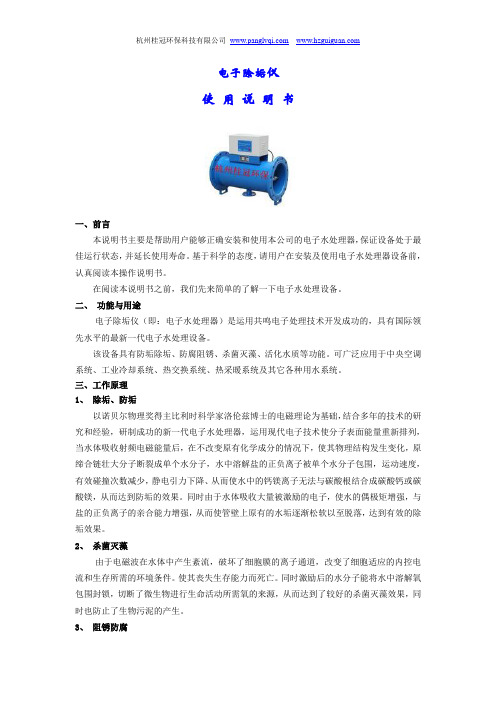
电子除垢仪使用说明书一、前言本说明书主要是帮助用户能够正确安装和使用本公司的电子水处理器,保证设备处于最佳运行状态,并延长使用寿命。
基于科学的态度,请用户在安装及使用电子水处理器设备前,认真阅读本操作说明书。
在阅读本说明书之前,我们先来简单的了解一下电子水处理设备。
二、功能与用途电子除垢仪(即:电子水处理器)是运用共鸣电子处理技术开发成功的,具有国际领先水平的最新一代电子水处理设备。
该设备具有防垢除垢、防腐阻锈、杀菌灭藻、活化水质等功能。
可广泛应用于中央空调系统、工业冷却系统、热交换系统、热采暖系统及其它各种用水系统。
三、工作原理1、除垢、防垢以诺贝尔物理奖得主比利时科学家洛伦兹博士的电磁理论为基础,结合多年的技术的研究和经验,研制成功的新一代电子水处理器,运用现代电子技术使分子表面能量重新排列,当水体吸收射频电磁能量后,在不改变原有化学成分的情况下,使其物理结构发生变化,原缔合链壮大分子断裂成单个水分子,水中溶解盐的正负离子被单个水分子包围,运动速度,有效碰撞次数减少,静电引力下降、从而使水中的钙镁离子无法与碳酸根结合成碳酸钙或碳酸镁,从而达到防垢的效果。
同时由于水体吸收大量被激励的电子,使水的偶极矩增强,与盐的正负离子的亲合能力增强,从而使管壁上原有的水垢逐渐松软以至脱落,达到有效的除垢效果。
2、杀菌灭藻由于电磁波在水体中产生紊流,破坏了细胞膜的离子通道,改变了细胞适应的内控电流和生存所需的环境条件。
使其丧失生存能力而死亡。
同时激励后的水分子能将水中溶解氧包围封锁,切断了微生物进行生命活动所需氧的来源,从而达到了较好的杀菌灭藻效果,同时也防止了生物污泥的产生。
3、阻锈防腐当水体接受电磁能量的作用后,单个水分子包容了溶解在水中的氧分子,使溶解氧成为惰性氧,切断了金属锈蚀所需氧的来源。
同时,电磁波激起的悬垂复合调制频率的电磁场所产生的“集肤效应”在管壁上聚集了过剩的负,而水体内部聚集了过剩的正电荷,水中过剩的正电荷强烈排斥带正电的同性Fe+,阻止Fe失去电子变为Fe+从金属壁分离进入水中,(系统中产生的黄色锈水就是Fe+在水中呈现的颜色)。
A151 实验室电导率仪 中文使用手册说明书
A151实验室电导率仪中文使用手册简介感谢您选择般特仪器的A151实验室电导率仪,这本操作手册循序渐进的描述了仪表的各项功能与特征。
使用前,请仔细阅读。
使用环境打开包装前,请确保当前工作环境符合以下条件:•相对湿度小于80%•环境温度大于0°C并且小于60°C•无潜在的电磁干扰装箱单以下列表描述了仪表出厂时的标准组件。
拆箱后,请检查所有部件是否齐全。
如有缺失或损坏,请立即联络般特仪器授权销售商。
A151电导率仪电极架电导标准液CON-1电导电极TP-10K温度探棒DC12V电源适配器按键功能连接器安装电极架取出包装盒内的电极架。
翻转仪表,对准电极架底座与仪表的圆孔,将2颗螺钉适度拧入。
安装后,如果电极臂自动升起或落下,您需要适度调节电极架内的螺钉直至电极臂可以在任何位置定位。
1. 取下电极臂右侧的塑胶盖。
2. 使用十字螺丝刀适度拧紧螺钉。
3. 安装塑胶盖至先前的位置。
连接电极1. 取出包装盒内的电导电极,按下述步骤将电极插入电极臂的左或右侧。
1. 插入电极2. 勾入线缆3. 勾入线缆2. 将电极的6针连接器插入仪表背面板标有EC/DO的连接器座,确保连接器完全就位。
连接完成后,请勿拉拽线缆,始终保持连接器清洁干燥。
连接温度探棒1. 取出包装盒内的温度探棒并插入电极臂中间的圆孔。
2. 将温度探棒的连接器插入仪表背面板标有°C的连接器座,确保连接器完全就位。
连接电源适配器1. 连接电源适配器前,请确保其电压及规格符合您所在国家的供电要求。
2. 将电源适配器插入电源座,仪表现在可以使用了。
开关仪表• 按住键,仪表开机,屏幕显示测量值。
• 按住键3秒,仪表关机。
如果您需要启用自动关机功能,请参阅【设置菜单】一节所述。
设置菜单A151电导率仪包含一个完整的设置菜单用于自定义各项参数以符合测量需求,下表描述了各菜单项的功能。
设置默认选项1. 在测量模式,按住键3秒进入设置菜单。
飞利浦空气清洁机AC1711操作手册说明书

使用手冊AC1711目錄1 重要事項 (1)安全 (1)電磁場 (EMF) (2)回收 (2)2 您的空氣清淨機 (3)產品概覽 (3)控制項概覽 (4)3 快速入門 (5)安裝濾網 (5)接上電源 (5)4 使用空氣清淨機 (6)瞭解空氣品質指示燈 (6)開關機 (6)變更模式設定 (7)切換顯示指示燈 (8)使用開/關燈按鈕 (8)5 清潔與維護 (9)清潔排程 (9)清潔空氣清淨機的機體 (9)清潔微粒感測器 (9)清潔濾網表面 (10)更換濾網 (11)濾網重設 (12)6 收納 (12)7 疑難排解 (13)8 保固與支援 (14)訂購零件或配件 (14)1 重要事項安全在使用本產品前,請先仔細閱讀本使用手冊,並保留使用手冊以供日後參考。
危險• 請勿用水、其他液體或是 (易燃) 清潔劑清潔產品,也請勿讓該物質進入產品內,以避免觸電和/或火災。
• 請勿在產品周圍噴灑殺蟲劑或芳香劑等任何易燃物質。
警告• 插電之前請先確認產品標示的電壓是否與當地使用的電壓相符。
• 如果電源線損壞,您必須將其交由飛利浦、飛利浦授權之服務中心,或是具備相同資格的技師進行更換,以免發生危險。
• 當插頭、電源線或產品本身受損時,請勿使用本產品。
• 請僅使用產品隨附之經核准的轉接器 (KA3601A-2401500TW)。
• 本產品可供 8 歲以上孩童及身體、知覺或精神能力障礙者或經驗與知識缺乏者使用,但需向他們提供安全使用產品相關的監督或指示說明,且他們必須瞭解可能發生的危險。
• 請勿讓孩童把玩產品。
• 若無人在旁監督,不得讓孩童清潔與維護本產品。
• 請勿在出風口上方或進風口前面放置物品,擋住進出風口。
• 確定沒有異物透過出風口掉入產品。
注意• 本產品不可用來作為維持良好通風的設備、替代吸塵器清潔,或烹調時用來當作抽油煙機使用。
• 請一律將本產品放置在乾燥平穩的水平面上使用。
• 產品周圍須至少保留 20 公分的間隔距離,頂部則至少保留 30 公分的間隔距離。
DA 系列多功能电子除垢仪
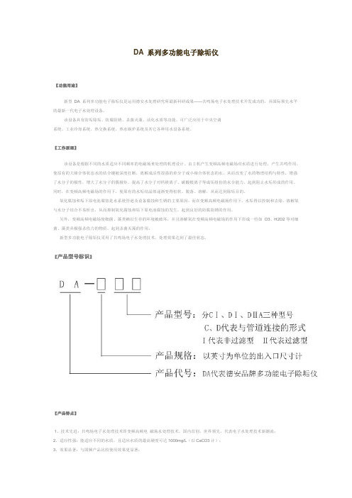
DA 系列多功能电子除垢仪【功能用途】新型DA 系列多功能电子除垢仪是运用德安水处理研究所最新科研成果——共鸣场电子水处理技术开发成功的,具国际领先水平的最新一代电子水处理设备。
该设备具有防垢除垢、防腐阻锈、杀菌灭藻、活化水质等功能。
可广泛应用于中央空调系统、工业冷却系统、热交换系统、热水锅炉系统及其它各种用水设备系统。
【工作原理】该设备是根据不同的水质适应不同频率的电磁场来处理的机理设计。
由主机产生变频高频电磁场对水质进行处理,产生共鸣作用,使原有的大缔合体状态水的结合键被深度打断,离解成活性很强的单分子或小缔合体状态的水,从而改变了水的物理结构与特性,增强了水分子的极性,增大了水分子的偶极矩,提高了水分子对钙镁离子、碳酸根离子等成垢组份的水合能力,起到阻止水垢形成的作用。
同时,在变频高频电磁场的作用下,使原有的水垢结晶体逐渐变得松软、脱落、溶解,从而达到除垢目的。
氧化腐蚀和垢下原电池腐蚀是水系统管道及设备腐蚀和生锈的主要原因,而在变频高频电磁场作用下,水垢得以控制和去除,溶解氧与水分子结合不易析出,从而抑制氧化腐蚀和垢下原电池腐蚀的发生,起到良好的防腐阻锈的作用。
另外,变频高频电磁场使细菌、藻类赖以生存的环境被破坏,并且溶解氧在变频高频电磁场的作用下形成一些如O3、H2O2等对细菌、藻类具极强杀伤力的物质,起到杀菌灭藻的作用。
新型多功能电子除垢仪采用了共鸣场电子水处理技术,处理效果达到了最佳状态。
【产品型号标识】【产品特点】1、技术先进:共鸣场电子水处理技术即变频高频电磁场水处理技术,国内首创,世界领先,代表电子水处理技术新潮流;2、适应性强:能适应不同的水质,且适应水质的最高硬度可达1000mg/L(以CaCO3计);3、效果显著:与固频产品比较使用效果更显著;4、能耗小:比固频产品能耗下降50%以上;5、体积小:比固频产品体积小30%以上;6、重量轻:比固频产品重量轻50%以上;7、阻力小:DⅠ型阻力系数仅为0.2;8、寿命长:新型除垢仪的使用寿命达20年以上;9. 有过滤功能:Ⅱ型除垢仪带有过滤功能,可省去管路系统上的过滤设备。
Philips GC610 GC612 ProTouch蒸汽衣具饰物批量清洁机说明书

/welcome用户手册a衣架b衣杆固定扣c衣杆d水箱e底座f衣杆释放锁g蒸汽管h蒸汽喷头i毛刷j防烫手套k衣领架l裤夹衣架a Hangerb Pole clipsc Polesd Water tanke Basef Pole release lockg Steam supply hoseh Steamer headi Brushj Glovek Collar aidl Pants hangerEN ZH-S4ENIntroductionCongratulations on your purchase and welcome to Philips! To fully benefit from the support that Philips offers, register your product at /welcome.ImportantRead this important information carefully before you use the appliance and save it for future reference.Danger-Never immerse the appliance in water or any other liquid, nor rinse it under the tap.Warning-Check if the voltage indicated on the type plate of appliance corresponds to the local mains voltagebefore you connect the appliance.-Do not use the appliance if the plug, the mains cord or the appliance itself shows visible damage, or if theappliance has been dropped or leaks.-Do not connect the appliance to a D.C. Supply.-Always return the appliance to a service centre authorised by Philips for examination or repair. Do not attempt to repair the appliance yourself, otherwise the guarantee becomes invalid.-If the mains cord is damaged, you must have it replaced by Philips, a service centre authorised byPhilips or similarly qualified persons in order to avoida hazard.-Never leave the appliance unattended when it is connected to the mains.-This appliance can be used by children aged from8 years and above and persons with reduced physical,sensory or mental capabilities or lack of experience7and knowledge if they have been given supervision or instruction concerning use of the appliance in a safe way and understand the hazards involved.-Children should be supervised to ensure that they do not play with the appliance.-Cleaning and user maintenance shall not be made by children without supervision.-When you have finished steaming, when you fill or empty the water tank, when you perform cleaning and rinsing, and also when you leave the appliance even for a short while, remove the mains plug from the wall socket.-Keep the appliance and its mains cord out of reach children.-Only connect the appliance to an earthed wall socket.Caution-Check the mains cord regularly for possible damage. -Beware of hot steam and hot water that comes out from steamer nozzle during use. Steam and hot water can cause burns.-The nozzle of steamer head can become extremely hot and may cause burns if touched.-This appliance is intended for household use only.-Do not place the steamer base on top of table or chair but rather keep the steamer base on the floor during usage duration.-If the hose forms a U shape, steam condenses in the hose. This causes irregular steam or water droplets to come out of the steamer head.-Steam may damage or cause discolouration of certain wall or door finishes.-Do not use the appliance when the water tank is empty.-Do not let the mains cord come into contact with hot steam when the appliance is in operation.8警告--在将产品连接电源之前,请先检查产品所标电压与当地的供电电压是否相符。
北京坎贝尔Canpure EDI用户手册
控制浓水的电导率在50到600S/cm之间。
3.4
进水电导率低时,坎贝尔™EDI模块的电流较小,这样会影响产品水水质。这时可以选择加盐装置,来提高浓水电导率。
加盐装置一般包括计量泵、盐箱和低液位开关。
计量泵最好由PLC控制自动运行,当浓水循环泵启动并且浓水电导率低于设定值时计量泵开始工作。
氯和臭氧会氧化离子交换树脂和离子交换膜,引起EDI组件功能减低。氧化还会使TOC含量明显增加,污染离子交换树脂和膜,降低离子迁移速度。另外,氧化作用使得树脂破裂,通过组件的压力损失将增加。
铁和其它的变价金属离子可对树脂氧化起催化作用,永久地降低树脂和膜的性能。
硬度能在反渗透和EDI单元中引起结垢。结垢一般在浓水室膜的表面发生,该处pH值较高。此时,浓水入水和出水间的压力差增加,电流量降低。坎贝尔™组件设计采取了避免结垢的措施。不过,使入水硬度降到最小将会延长清洗周期并且提高EDI系统水的利用率。
在每个组件建议的电压范围内,最佳电压取决于给水电导率和水的回收率。给水中较多的离子迁移流量和较高的水回收率使得离子在浓水室中高度浓缩,这将降低膜堆的电阻,从而使最佳电压降低。
4.1.3
运行条件改变后,组件将需要运行8-24个小时才能达到稳定状态。稳定状态是指进出组件的离子达到物料平衡。
如果电压降低或给水离子浓度增加,树脂将会吸收多余的离子。在这种状态下,离开组件的离子数将小于进入组件的离子数。最后达到新的稳定状态时离子迁移速率和给水离子相协调。此时,离子交换树脂的工作前沿将向出水端移动。
一般城市水源中存在钠、钙、镁、氯化物、硝酸盐、碳酸氢盐等溶解物,这些化合物由带负电荷的阴离子和带正电荷的阳离子组成。通过反渗透(RO)的处理,98%以上的离子可以被去除。RO纯水(EDI给水)电阻率的一般范围是0.05-0.25MΩ·cm,即电导率的范围为20-4μS/cm。根据应用的情况,去离子水电阻率的范围一般为1-18.2MΩ·cm。另外,原水中也可能包括其它微量元素、溶解的气体(例如CO2)和一些弱电解质(例如硼,二氧化硅),这些杂质在工业除盐水中也必须被除掉。但是反渗透过程对于这些杂质的清除效果较差。
Aqusoften电子除垢仪简介
Aqusoften电子除垢仪是一台设备也是一个系统,产品设计先进、结构简单、用途广泛、效果显著,深受用户喜爱的除垢防垢、杀菌灭藻理想产品。
优势:1、适用于任何材质的管道2、系统的自动记忆程序保证其正常运行。
为防止可能出现的电力一故障,系统能够在电源恢复时,自动复位到现在故障前的程序。
3、不依赖水的流量和速度影响。
并在任何时候都能不间断提供可靠信号输出。
4、系统工作频率范围在100Hz-200KHz且有不同的峰值,结合出大量高性能除垢防垢信号5、系统耗电少,节能环保。
该系统的运行功率从1.2至100瓦之间,每年的运行成本约7-219元。
6、系统提供长达10年的国际保修书。
特殊的壳体保护可以使系统持续工作30年以上。
7、Aqusoften水处理设备自动运行无需人工护。
性能:当水流经过Aqusoften除垢系统,系统电磁波促使水垢凝结且悬浮于水中,不粘附在管道上,随水流流走,有效防止管道和设备表面结垢。
Aqusoften水处理改变结垢过程和自然分解之间的过程。
使水垢积聚逐渐减少。
且保持水垢清除速度快于新增速度。
同时,分解出的碳酸也有助于清除原有的沉积。
渐渐地,管道陈垢也被清除。
杀菌灭藻当藻类孢子和细菌诵过Aqusoften水处理器时,Aqusoften设备会细化水分子,使水分子比细胞膜还小,水分子直接渗透细胞体内,细胞生态平衡被打破继而破裂死亡。
常州沛德水处理设备有限公司成立于2004年,专注于循环水物理法水质优化处理的解决方案并研发生产了物理法除垢、杀菌、灭藻、缓蚀设备以及循环水处理的过滤设备,定压补水,真空气设备等相关设备,先后申报数十项专利,是知名的循环水系统物理法除垢、杀菌、灭藻、过滤解决方案的供应商,沛德先后已为秦山核电、红沿河核电、万达广场、可口可乐、雪花啤酒、等多家企业提供水垢解决方案及服务。
迪亚尔brand电子厨Sink 50N 32使用指南与维护指南说明书

Instructions for use and maintenance of gas, gas-electric and electric cookers. Series:32-Thank you for choosing one of our quality products, capable of giving you the very best service. To make full use of its perfor-mance features, read the parts of this manual which refer to your appliance carefully. The Manufacturer declines all responsibility for injury or damage caused by poor installation or improper use of the appliance.-To ensure its appliances are always at the state of the art, and/or to allow constant improvement in quality, the manufacturer reserves the right to make modifications without notice, although without creating difficulties for users.-When ordering spare parts, inform your dealer of the model number and serial number punched on your appliance’s nameplate, visible inside the warming compartment or on the back of the cooker.-APPLIANCE COMPLYING WITH THE FOLLOWING DIRECTIVES:- EEC 90/396- EEC 73/23 and 93/88-EEC 89/336 (radio-frequency inter-ference)- EEC 89/109 (contact with foods)FOREWORD-Refer only to the headings and sections covering accessories actually installed on your cooker.Technical data andspecifications.............................33Installation..........................34 - 36Ventilation......................................34Positioning.....................................34Gas connection .............................34Adapting to different typesof gas ............................................35Replacing the injectors ..................35Regulating the air ..........................35Minimum setting ............................35Electrical connection .....................36Safety device (36)For the user....................... 37 - 40Ventilation......................................37Igniting the burners....................... 37Igniting the gas oven .................... 37Igniting the gas grill .......................37Safety device.................................37Using the gas hob .........................37Using the electric hot-plates ..........37Using the gas oven........................38Using the gas or electric grill ........38Using the conventionalelectric oven ..................................38Using the conventionalmultifunction electric oven .............39Oven with thermostat ....................39Warming compartment ..................39Advice and precautions.. (39)Figures .............................. 41 - 43ELECTRIC HOTPLATESø 1451,0 kW - Normal hotplate1,5 kW - Rapid hotplateø 1801,5 kW - Normal hotplate2,0 kW - Rapid hotplate ELECTRIC OVEN POWEROven: (1,1kW bottom0,7kW top element)2,2 kW Grill:2,0 kW Cat.: see nameplate on cover; Class 1 or 2.1 Type “X” cookersEQUIPMENTAll models are equipped with safety device for oven and grill burners.Depending on the models, cooker may also have:-Oven thermostat (or tap)-Electric oven lighting-Grill burner or element-One or more electric hotplatesFor the LAYOUT OF HOB BURNERS see the models illustrated in figure 1 at the back of this manual.For the ELECTRIC WIRING DIAGRAM see figure 2 at the back of this manual.The electrical power is stated on the name-plate visible inside the warming compartment (if present) or on the back of the cooker.A copy of the nameplate is glued to the coverof this manual (for gas or gas-electric prod-ucts only).33INSTALLATIONThe appliance must be installed by qualified staff working in accordance with the regula-tions in force.Before installing, ensure that the appliance is correctly preset for the local distribution conditions (gas type and pressure).The presettings of this appliance are indi-cated on the nameplate shown on the cover. This appliance is not connected to a flue gas extractor device. It must be installed and connected in accordance with the regulations in force.This appliance may only be installed and may only operate in rooms permanently ventilated in accordance with national regulations in force.VENTILATIONThe rooms in which gas appliances are in-stalled must be well ventilated in order to al-low correct gas combustion and ventilation. The air flow necessary for combustion is at least 2 m3/h for each kW of rated power. POSITIONINGRemove the packaging accessories, includ-ing the films covering the chrome-plated and stainless steel parts, from the cooker. Position the cooker in a dry, convenient and draft-free place. Keep at an appropriate dis-tance from walls which may be damaged by heat (wood, linoleum, paper, etc.).The cooker may be free-standing (class 1) or between two units (in class 2 st 2-1) the sides of which must withstand a tempera-ture of 100°C and which must not be higher than the working table.CONNECTING TO THE GAS SUPPLY Before connecting the cooker, check that it is preset for the gas to be used. Otherwise, make the conversion as described in the section headed “Adapting to different gas types”. The connection is on the right; if the pipe has to pass behind the cooker, it must be kept low down where the temperature isabout 50°C.-Rigid connection (see fig. 3 A + B)The connection to the mains gas supplymay be made using a rigid metal pipe orwith a metal hose. Remove the hose con-nector (if already fitted) and screw the rigidunion onto the threaded connection of thegas train (see fig. 3A). The union for rigidconnection may already be fitted on the gastrain, or may be amongst the cooker ac-cessories. Otherwise, it can be obtainedfrom your dealer.If national regulations permit, a metal hosecomplying with the national standards canbe screwed directly onto the threaded con-nection of the gas train, fitting a seal (seefig. 3B). However, users are strongly rec-ommended always to fit the rigid union.-Connection using a rubber hose (see fig.3C). (For butane/propane gas only).Connect a rubber hose carrying the con-formity mark currently in force to the hoseconnector. The hose must be replaced atthe date indicated at the latest, and mustbe secured at both ends using stand-ard hose clamps. It must be absolutelyaccessible to allow its condition to bechecked along its entire length.CAUTION:-Use of the hose connector is only per-mitted for free-standing installation. Ifthe appliance is installed between twoclass 2 st. 2-1 unions, the rigid union isthe only form of connection permitted.IMPORTANT:-After installation, check that the connec-tions are airtight.-For operation with butane/propane, checkthat the gas pressure is as indicated on thenameplate.-Use only standard rubber hoses. For LPG,use a hose which complies with the nationalregulations in force.-Avoid sharp bends in the pipe and keep itwell way from hot surfaces.References to the regulations covering the gas connection to the appliance: ISO 7-1.34ADAPTING TO DIFFERENT TYPES OF GASIf the cooker is not already preset to operate with the type of gas available, it must be con-verted. Proceed as follows:-Replace the injectors (see table on page 33);-regulate the primary air flow;-regulate the minimum settings.N.B.: every time you change the type of gas, indicate the new type of gas on the serial number label.REPLACING THE HOB BURNER INJEC-TORS (fig. 4)-Remove the lid of the cooker by lifting it off its supports;-remove the grids, burner caps and burn-ers, lifting them off;-unscrew the 2 screws (above) or nuts (be-low) at the back which secure the work top, and pull it out forward.-remove the mixer pipes and replace the injectors using a 7 mm socket wrench. REPLACING THE OVEN BURNER INJEC-TOR (Fig. 5)-Loosen the screw which secures the bot-tom of the oven;-remove the oven bottom (pulling it forward); -remove the oven burner, after taking out the screw which secures it;-replace the injector using a 7 mm socket wrench.REPLACING THE GRILL BURNER INJEC-TOR (Fig. 6)-Remove the burner after taking out the two screws which secure it;-replace the injector using a 7 mm socket wrench.IMPORTANT:-Never over-tighten the injectors;-after replacing, check that all the injectors are airtight.Burner G20 20mbar G30 28-30mbarG31 37mbar Auxiliary3 4Semi-rapid3 3Rapid4 6Oven- -Grill3 8REGULATING THE BURNER AIRRefer to the table below (indicative values) for regulation of the gap H in mm (fig. 4 for the hob, fig. 6 for the grill).Check operation of the burner:-Ignite the burner at maximum flame;-the tongue of the flame must be clear andwith no yellow tip, and must adhere closelyto the burner. If too much air is supplied,the flame detaches from the burner andmay be dangerous. If the air supply is in-sufficient, the flame has a yellow tip andsoot may form.SETTING HOB BURNER MINIMUM LEV-ELSIf the cooker is to work on bottled gas (bu-tane/propane), the tap by-pass must be screwed right down.The cooker may be equipped with type A taps, with by-pass inside (accessed by in-serting a small screwdriver into the rod) or type B taps, with by-pass on the outside on the right (accessed directly). See figure 7.If the cooker is to work on natural gas, pro-ceed as follows for both types of tap:-Ignite the burner at maximum flame;-pull off the knob, without using a leveragainst the control panel, which might bedamaged;-access the by-pass with a small screwdriverand back off by about 3 turns (turning thescrewdriver anti-clockwise);-turn the tap rod anti-clockwise again until itstops: the burner will be at maximum flame;-screw the by-pass slowly back in, withoutpushing the screw-driver, until the flame hasapparently shrunk to 1/4 of the maximumsize, checking that it is sufficiently stable35even in quite strong draughts.SETTING OVEN BURNER MINIMUM LEV-ELSIf the cooker is to work on bottled gas (bu-tane/propane), the thermostat by-pass must be screwed right down.If the cooker is to work on natural gas, pro-ceed as follows:-Remove the oven bottom (loosen the screw to remove the bottom);-ignite the oven burner, turning the knob pointer to the maximum setting;-shut the oven door;-access the thermostat or tap by-pass (see fig. 8);-back off the thermostat by-pass by about 3 turns;-after 5 or 6 minutes, turn the knob pointer to the minimum setting;-slowly re-tighten the by-pass, watching the flame decrease in size through the window in the closed oven door until the tongue of the flame is about 4 mm long. Never keep the flame too low. It must be stable even when the oven door is opened or closed quickly;-turn off the burner and replace the oven bottom.CONNECTING TO THE ELECTRICAL MAINSBefore making the connection, check that: -the mains voltage is as indicated on the nameplate;-the earth connection is in good working or-der.If the socket is not easily accessible, the in-stallation engineer must provide a switch with a contact breaking gap of 3 mm or more.If the appliance power lead is not fitted with a plug, use an approved standard type, re-membering that:-the green-yellow wire must be used for the earth connection;-the blue wire is the neutral;-the brown wire is live;-the lead must never touch hot surfaces overabout 75 degrees C;-replacement leads must be of type H05RR-F or H05V2V2-F of suitable size (see dia-grams in fig. 2).-if the appliance is supplied without lead,using type H05RR-F or H05V2V2-F cableof suitable size (see diagrams in fig. 2).IMPORTANT: the manufacturer declines all liability for damage due to failure to comply with the regulations and standards in force.Check that the appliance is correctly con-nected to the earth (see diagrams in fig. 2 at the back of the manual).THE SAFETY DEVICEThe correct gap between the end of the ther-mocouple sensor and the burner is shown in figures 5 and 6.To check that the valve is working properly, proceed as follows:-ignite the burner and leave it to work forabout 3 minutes;-turn off the burner by returning the knob tooff position (-turn the knob pointer to the "on" position;-release the knob in this position and movea burning match towards the burner; ITMUST NOT IGNITE.Time needed to excite the magnet during ignition: 10 seconds approx.Automatic tripping time, after flame has been turned off: not more than 60 seconds for oven and grill burners.IMPORTANT-Before doing any work inside the cooker, dis-connect the mains plug and shut the gas tap.-Never use matches to check the gas cir-cuit for leaks. If a specific control device isnot available, foam or very soapy water canbe used.-When re-closing the hob, check that theelectrical wires of the spark plugs (ifpresent) are not close to the injectors, sothat they cannot run across them.36HOW TO USE THE COOKER VENTILATIONAll gas cooking appliances produce heat and moisture in the rooms where they are in-stalled. Take care to ensure that the kitchen is well ventilated; keep the ventilation open-ings unobstructed or install an extractor hood with fan.In case of intensive or prolonged use, addi-tional ventilation may be required; open a window, or increase the extractor fan power. IGNITING THE HOB BURNERS-Press the knob and turn it anti-clockwise-at the same time, move a burning match towards the burner head;-to reduce the flame, turn the knob further in the same direction until its pointer issition).IGNITING THE OVEN BURNER-Open the oven door;-press the knob and turn it anti-clockwise to the maximum flame position;-move a burning match towards the hole in the centre of the oven bottom and press the knob right down (see fig. 9);-check that the burner has ignited, looking through the hole in the centre of the bot-tom, keeping the knob pressed all the time; -after about 10 seconds, release the knob and check that the burner remains on. Oth-erwise, repeat the operation.IGNITING THE GRILL BURNER (GAS GRILLS)-Fit the control knob guard as shown in fig. 12;-press the oven knob and turn it to the right until it reaches the stop;-move a burning match towards the perfo-rated burner pipe and press the knob right down (see fig. 10);-check that the burner has ignited, keepingthe knob pressed down;-after about 10 seconds, release the knoband check that the burner remains on. Oth-erwise, repeat the operation.IMPORTANT-Difficulty in igniting burners is normal if thecooker has been out of use for some time.The air accumulated in the pipes will beexpelled in a few seconds;-Never allow too much unburnt gas to flowfrom the burners. If ignition is not achievedwithin a relatively short time, repeat the pro-cedure after returning the knob to the offposition (-time, a smell may be noticed and smokemay come out of the oven. This is becauseof the surface treatment and oily residueson the burners.SAFETY DEVICEBurners equipped with this device have the advantage that they are protected if they accidentally go out. If this occurs, the supply of gas to the burner concerned is automati-cally cut off, preventing the hazards deriving from a leak of unburnt gas. The gas supply must be cut off within no more than 60 sec-onds for the oven and grill burners.HOW TO USE THE HOB BURNERSUse pans of diameter suitable for the burner type. The flames must not project beyond the base of the pan. Recommended sizes: -for auxiliary burners = pans of at least 8 cm -for semi-rapid burners = pans of at least 14 cm -for rapid burners = pans of at least 22 cm.N.B.: Never keep the knob at settings be-off position .FOR COOKERS EQUIPPED WITH ELEC-TRIC HOTPLATESThe different heat settings are obtained as follows:37- 1 = minimum setting for all hotplates;- 6 = maximum setting for normal and rapid hotplates (with red disc);- 0 = off.Pans must never be smaller in diameter than the hotplates and their bottoms must be as flat as possible (see fig. 11). IMPORTANT:-Never leave hotplates on without pans, except when first used; leave for about 10 minutes to dry oil or moisture residues;-if the hotplate is to be out of use for a long time, apply a little grease to its painted surface; -do not allow spills to burn onto the hotplate, requiring the use of abrasive cleaners. HOW TO USE THE GAS OVEN-After igniting the burner, leave the oven to heat up for about 10 minutes;-place the food for cooking in an ordinary oven dish and place it on the chrome-plated shelf; -place the food in the oven, using the shelf on the third pair of runners whenever possi-ble, and turn the knob pointer to the desired setting;-cooking can be observed through the window in the door with the oven light on. This will avoid opening and closing the door frequently, unless oil or fat has to be added to the dish. IMPORTANT: never place foods directly on the drip tray for cooking; it is there only to collect any drips of fat during grilling.N.B.: For cookers without thermostat:-270 degrees C-150 degrees C-All other temperatures between 150 and 270 degrees C are obtained approximately by positioning the knob between the maxi-mum and minimum settings.Never leave the knob in positions between theHOW TO USE THE GAS OR ELECTRIC GRILL-fit the knob guard (see fig. 12);-ignite the burner and wait a few minutes toallow it to warm up, or switch on the heat-ing element;-place the foods on the chrome-plated shelf;-insert on the highest runner;-insert the drip tray on the bottom runner;-gently close the oven door, resting it againstthe knob guard;-after a few minutes, turn the food to exposethe other side to the infrared radiation (thecooking time depends on the type of foodand personal taste).N.B.: the first time the grill is used smoke will come out of the oven. Before inserting foods for cooking, wait until any oil residues on the burner have completely burnt away.The grill must only be used at its full rated heat.IMPORTANT: accessible parts may be hot when the grill is in use! Keep children well away.The grill element in the top of the oven is switched on by turning the thermostat knob clockwise to the grill symbol on the control panel.The red light will come on to show the ele-ment is in operation.The table below will serve as a guide; bear-ing in mind that cooking times and tempera-tures may vary depending on the type and amount of foods cooked and personal taste.Food to be Time (minutes)grilled1st side2nd sideThin pieces of meat 6 4Fairly thick pieces ofmeat 8 5Thin fish or fishwithout scale10 8Fairly thick fish1512Sausages1210Toasted sandwiches 5 2Small poultry2015CONVENTIONAL ELECTRIC OVEN-The oven shelf is designed to take normaloven dishes for cooking sweets or roasts,3839-The oven shelf is designed to take normal oven dishes for cooking sweets or roasts,or is used without a pan for cooking foods under the grill.-The drip tray is only there to collect any juice from foods and must never be used as a cooking surface.OVENS WITH THERMOSTATIf cooking temperatures are not as set, call in an engineer to check the thermostat.WARMING COMPARTMENTTo open the warming compartment, open the flap door with one hand (see figure 13).To close the warming compartment, simply press the flap door back into place.GENERAL PRECAUTIONS-Always disconnect the power supply before any work inside the oven or where live parts may be accessed.-Never use the warming compartment for storing inflammable liquids or items which do not withstand heat, such as wood, pa-per, aerosol cans, matches, etc.-Make frequent checks on the rubber con-nection hose, ensuring that it is well away from hot surfaces, that there are no sharp bends or kinks, and that it is in good condi-tion. The hose must be replaced at the lat-est at the indicated date and must be se-cured at both ends using a standard hose clamp.-If taps become stiff to operate over time,contact the After-Sales service.-Wash enamelled or chrome-plated parts with soapy lukewarm water or non-abrasive detergents. A metal brush may be used to remove deposits from hob burners and flame caps. Dry thoroughly.-Never use abrasives to clean enamelled or chrome-plated parts.-Do not use too much water when washing the hob. Take care that no water or other substances enter the burner housing holes,as this may be dangerous.or is used without a pan for cooking foods under the grill.-The drip tray is only there to collect any juice from foods and must never be used as a cooking surface.There is a single control knob for the oven or grill.Starting from the 0 (off) position, the knob can be turned clockwise to the following settings:--The spark plugs for electric ignition mustbe kept clean and dry; always check after use, particularly if there have been drips or overflows from pans.-Never close glass lids until the hob burn-ers or hotplates have cooled completely; it might shatter or crack.-Never knock enamelled parts or ignition spark plugs (where present).-The main or wall gas tap should be turnedoff when the cooker is not in use.-Never lift the cooker by taking hold of the oven door handle.No liability is accepted for injury or damage caused by poor installation or improper useof the cooker.In case of malfunctions, particularly gas leaks or short-circuits, contact your en-gineer without delay.404142587634mm 2 - 4HBA43121011ED. 09.02.1999334813B1/44。
电子除垢仪说明书

电子除垢仪说明书一、产品概述由于水系统中大量的钙镁离子难以在前期得到有效处理,因此后续水系统在温度的作用下析出CO2生成微溶于水的CaCO3和MgCO3。
由于CaCO3和MgCO3的溶解度随温度的上升而下降,从水中结晶析出,并不断地沉积于换热器等设备系统表面,对能耗及连续产生重大影响。
电子除垢仪的应用可以有效控制90%以上垢质的生成,因此也就意味着减少90%以上的能耗损失,同时最大限度的保证了连续生产。
二、工作原理电子除垢仪的基本原理是改变导致管垢形成的物理分子结构,运用磁力复合波纹来改变周围环境的条件以粉碎电离子间的键,以及令他们合成稳定的非管垢物质。
电子除垢仪的作用原理不同于以往任何物理化学除垢方法,其核心是一个调制信号发生器。
采用独特的集成电路和信号处理技术,产生一种复杂频率的调制信号,通过信号电缆将该调制信号加在管道上,在管道内部产生一个分子力动态干扰场,作用于管道中的流体和溶于其中的溶盐分子,产生一种核化效应。
三、原理分析1、阻垢及除垢原理它的原理是利用综合电波改变水里的钙、镁等离子的物理结构,变成不溶于水的新结晶体,它们会悬浮于水里,不会粘附于管壁上,防止水垢形成。
由于钙镁等离子从水中析出,水便回复于高溶解状态,(水本身为高溶解度液体,但会因吸收其它物质而致饱和),当回复为高溶解状态的水流经有水垢的管道,便能把水垢溶解并吸收,并于排水时排走,因此,该产品除具有防止水垢形成外,还能有效清除老垢。
处理器内的微控制器会自动监视水流速率、水质和浓度等变化,因应情况释放正确的讯号电波。
自动干扰分子能量技术,专门控制CaCO3微晶基质的物理结构,造成CaCO3结晶体的霰石形式趋势。
2、杀菌灭藻由于电子除垢仪的高频电磁波在水体中产生紊流,破坏了细胞膜的离子通道,改变了细胞适应的内控电流和生存所需的环境条件。
使其丧失生存能力而死亡。
同时激励后的水分子能将水中溶解氧包围封锁,切断了微生物进行生命活动所需氧的来源,从而达到了较好的杀菌灭藻效果,同时也防止了生物污泥的产生。
物理去除水垢装置

物理去除水垢装置硬水和水垢的关系硬水来源于从富含钙和镁的岩石区域中流过或渗出的水,水中含有大量的这样的元素,但是,水中的这些元素都是人类和动物健康生活所必需的。
富含钙、镁等矿物质的水常常会因物理变化而在管道和设备中形成水垢。
物理变化包括温度和压力的改变,因此在管道中加热的水会比较容易形成水垢。
水垢在管道和设备中积聚,会增加加热时的能量消耗。
这会使设备的寿命减少,因此,用除垢仪对硬水进行处理以防止水垢的形成,这是非常有必要的。
井中或任何地下贮水池里的水大多是出于碳酸钙平衡状态。
抽水以及加热打破了这种平衡。
水为了重新获得平衡就需要析出一定量的碳酸钙沉淀物,就是通常所说的水垢。
安蒂克除垢装置能够改变硬水的性能,从而保留重要的钙、镁元素,同时还能避免水垢的形成和积聚。
安蒂克装置的说明安蒂克除垢装置是一种基础性的通用仪器,产地是斯洛伐克,安蒂克除垢装置可以防止水垢的形成,保护设备的安全,而且不添加任何化学品,安全环保。
安蒂克除垢装置经过多年的经验和开发研制而成,着重于其功能性、易于安装、效率和保护范围。
可以确保快速的投资回收。
该装置能够防止新水垢的形成,并能除去管道中已经形成的旧的水垢。
一台安蒂克设备包括一个电子设备和一个管道上的缠绕线圈。
电子设备装有一个发电机,能够给线圈和特定的控制和信号回路供电。
完整的设备是用特殊的材料密封包装的,避免对环境造成不利影响。
这保证了设备的较长使用时间(至少20年),同时保证了不会在高负荷条件下运作失败。
线圈组有至少两条线圈组成,从而确保了水量较大时的线圈的足够有效长度。
线圈是由配备有硅绝缘体的电缆组成的,可防高温达170℃,和其他不同的激进的环境影响。
安蒂克产品的特点:安蒂克除垢装置是根据在硬水处理方面多年的经验和知识为基础所进行的专业研究进行开发制作,具有以下优势:——能够节省您在去除硬质水垢方面耗费的时间。
——节约加热被水垢堵塞的电器中的水所使用的能量(水垢有隔热作用)。
alliance 洗脱机 固定式机体 安装操作保养手册说明书

汞 (Hg)
镉 (Cd)
六价铬 (CR[VI])
聚溴联苯 (PBB)
聚溴二苯醚 (PBDE)
PCBs
X
O
O
O
O
O
机电部件
O
O
O
O
O
O
电缆和电线
O
O
O
O
O
O
金属部件
O
O
O
O
O
O
塑料部件
O
O
O
O
O
O
电池
O
O
O
O
O
O
软管和管道
O
O
O
O
O
O
同步带
O
O
O
O
O
O
绝缘材料
O
O
O
O
O
O
玻璃
O
O
O
O
O
O
显示
O
O
O
O
O
• 请勿在洗涤剂盒的喷嘴(如适用)上装贴任何物体。必 须为此保留空气间隙。
• 如洗衣机上未安装循环水塞或循环水系统(如适用), 则不可操作本机。
• 请确保在水管连接时安装截止阀,进水管间连接紧密。 在结束清洗的当天,务必关闭截止阀。
• 请妥善保养洗衣机。如洗衣机遭撞击或发生坠落,安全 功能可能会受到损坏。如发生此类情况,请联系合格服 务人员检查机器。
重要安全说明
警告
在使用洗衣设备时,为降低发生火灾、触电、人员重伤或 死亡等风险,请务必遵守这些基本注意事项:
W023
• 请在使用本洗衣机前通读所有说明。 • 请遵照本安装说明安装洗衣机。请参考安装手册中 有关
电子除垢仪说明书
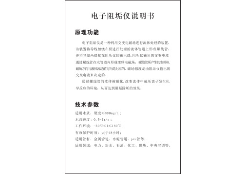
电子阻垢仪说明书原理功能电子阻垢仪是一种利用交变电磁场进行流体处理的装置,该装置将导线缠绕在要进行处理的流体管道上形成螺线管,并将导线两端接在阻垢仪的输出端,阻垢仪输出的交变电流通过螺线管在水管道内形成变频电磁场,螺线管所产生的变频电磁场方向与液体流动的方向是对应的,磁场强度是由阻垢仪输出的交变电流来决定的。
通过螺线管的流体被磁化,改变流体中成垢离子发生化学反应的环境,从而达到阻垢除垢的效果。
技术参数适用水质:硬度≤800mg/L;水流速度:0.5-4m/s;工作环境:-30℃≤T≤180℃;有效保护时效:大于48小时;适用管材:金属管道、水泥管道、pvc管等;适用领域:电力、冶金、石油、化工、供热、中央空调等。
设备型号管径mm尺寸L*W*Hmm 重量Kg 消耗功率W电压VQYCT-19250 50-80600*480*380 ≤50kg65220QYCT-19252 80-150 600*480*380 ≤50kg 200 220QYCT-19254 150-300 600*480*380 ≤50kg 400220QYCT-19256 300-400 600*480*380 ≤50kg 600 220QYCT-19258 400-500 600*1120*380 ≤100kg 800 220QYCT-192510 500-600 600*1120*380 ≤100kg 1000 220QYCT-192512 600-1000 600*1120*380 ≤100kg 1400 QYCT-192514 1000-1200 600*1120*380 ≤100kg 1800 220/380QYCT-192518 1200-1500 600*1120*380 ≤100kg 2700 220/380电子阻垢仪规格型号表220/380使用说明图1 面板简图1 主控电源板板2 控制板3 报警板4 输出板5 输出电源板6 主控电源板指示灯7 流量调节旋钮 8开关9 流量显示 10 报警指示灯11 输出电流显示 12 输出电源指示灯操作指南:1.开机:按下开关8,所有的电源指示灯亮,报警指示灯灭, 显示屏有显示,则系统正常。
DA 系列多功能电子除垢仪
DA 系列多功能电子除垢仪【功能用途】新型DA 系列多功能电子除垢仪是运用德安水处理研究所最新科研成果——共鸣场电子水处理技术开发成功的,具国际领先水平的最新一代电子水处理设备。
该设备具有防垢除垢、防腐阻锈、杀菌灭藻、活化水质等功能。
可广泛应用于中央空调系统、工业冷却系统、热交换系统、热水锅炉系统及其它各种用水设备系统。
【工作原理】该设备是根据不同的水质适应不同频率的电磁场来处理的机理设计。
由主机产生变频高频电磁场对水质进行处理,产生共鸣作用,使原有的大缔合体状态水的结合键被深度打断,离解成活性很强的单分子或小缔合体状态的水,从而改变了水的物理结构与特性,增强了水分子的极性,增大了水分子的偶极矩,提高了水分子对钙镁离子、碳酸根离子等成垢组份的水合能力,起到阻止水垢形成的作用。
同时,在变频高频电磁场的作用下,使原有的水垢结晶体逐渐变得松软、脱落、溶解,从而达到除垢目的。
氧化腐蚀和垢下原电池腐蚀是水系统管道及设备腐蚀和生锈的主要原因,而在变频高频电磁场作用下,水垢得以控制和去除,溶解氧与水分子结合不易析出,从而抑制氧化腐蚀和垢下原电池腐蚀的发生,起到良好的防腐阻锈的作用。
另外,变频高频电磁场使细菌、藻类赖以生存的环境被破坏,并且溶解氧在变频高频电磁场的作用下形成一些如O3、H2O2等对细菌、藻类具极强杀伤力的物质,起到杀菌灭藻的作用。
新型多功能电子除垢仪采用了共鸣场电子水处理技术,处理效果达到了最佳状态。
【产品型号标识】【产品特点】1、技术先进:共鸣场电子水处理技术即变频高频电磁场水处理技术,国内首创,世界领先,代表电子水处理技术新潮流;2、适应性强:能适应不同的水质,且适应水质的最高硬度可达1000mg/L(以CaCO3计);3、效果显著:与固频产品比较使用效果更显著;4、能耗小:比固频产品能耗下降50%以上;5、体积小:比固频产品体积小30%以上;6、重量轻:比固频产品重量轻50%以上;7、阻力小:DⅠ型阻力系数仅为0.2;8、寿命长:新型除垢仪的使用寿命达20年以上;9. 有过滤功能:Ⅱ型除垢仪带有过滤功能,可省去管路系统上的过滤设备。
微水仪操作规程
微水仪操作规程引言概述:微水仪是一种用于测量水样中微量水分含量的仪器,广泛应用于化工、制药、食品、环境等领域。
正确操作微水仪对于保证测试结果的准确性至关重要。
本文将从仪器准备、样品处理、操作步骤、数据记录和仪器维护等五个大点详细阐述微水仪的操作规程。
正文内容:1. 仪器准备1.1 确保微水仪处于正常工作状态。
检查仪器的电源、冷却系统、传感器等部件是否正常运行,如有异常应及时进行维修或更换。
1.2 清洁仪器。
使用干净的软布擦拭仪器表面,特别是传感器部分,确保无灰尘或杂质附着。
2. 样品处理2.1 准备样品。
按照测试要求取得代表性的水样,避免样品受到外界污染。
2.2 样品预处理。
根据需要,可以采用过滤、离心等方法去除样品中的杂质,确保测试结果的准确性。
2.3 样品装填。
将预处理后的样品装填到微水仪样品槽中,注意避免气泡和溢出。
3. 操作步骤3.1 打开微水仪软件。
根据仪器型号选择相应的软件,并确保软件与仪器连接正常。
3.2 设置测试参数。
根据样品性质和测试要求,设置测试温度、测试时间等参数。
3.3 开始测试。
点击“开始测试”按钮,仪器将自动进行测试,期间不得移动或干扰仪器。
3.4 记录测试结果。
测试完成后,将测试结果记录下来,包括水分含量、测试时间等信息。
4. 数据记录4.1 创建数据表格。
使用电子表格软件创建数据表格,记录测试日期、样品编号、水分含量等信息。
4.2 填写数据。
将每次测试的结果填写到相应的数据表格中,确保数据的准确性和完整性。
4.3 数据分析。
根据测试结果进行数据分析,可以使用统计软件进行数据处理和图表绘制,以便更好地理解和利用测试结果。
5. 仪器维护5.1 清洁仪器。
每次使用后,应及时清洁仪器,特别是样品槽和传感器部分,避免污染和积累。
5.2 定期维护。
按照仪器的使用说明书,进行定期的维护和保养,包括更换耗材、校准仪器等。
5.3 存放维护。
当不使用微水仪时,应将其存放在干燥、通风良好的地方,避免受潮或受到其他损害。
46洁定清洗机使用说明-关于使用、操作与日常维护
使用说明清洗消毒器Getinge 46-2, 46-4, 46-5 目录安全规范______________________________ 3重要信息_________________________________ 3产品责任____________________________________________3设备上的标志_______________________ 4绝缘设备____________________________________________4引起注意的符号__________________________ 4概要_______________________________________ _ 5编程装置__________________________________ 6门的操作_____________________________ 6干燥_____________________________________ 7加料系统_____________ _________________________ ____ 7操作说明____________________________ ___ 8____________________________________ ___ ___ 8故障指示________________________________ __ 9红灯亮___________________________ 9警报处理___________________________ _____ 9故障代码_________________ __________________________10故障代码的确认___________________________ _____ 11检查____________________________ __________ 12日常检查____________________________ ____________ 12必要时的检查_____________________ _____________13清洗室_________________ _______________________ 13外部检查___________________________ ___13Hospital A0 600 (90 o C - 1 min) _______________ __ 15Hospital A0 600 (90 o C - 1 min) _______________ __ 15LAB_______________ ____________________ ________ 16清洗剂_________________________________ _____ 17用于机械清洗的Getinge清洗剂______ __17酸性清洗剂和中和剂_ _ _______17润滑剂和增亮剂____________ _ ____________________17冲洗器清洗剂________________ ______________17安全规范该设备设计有一系列内置安全装置。
- 1、下载文档前请自行甄别文档内容的完整性,平台不提供额外的编辑、内容补充、找答案等附加服务。
- 2、"仅部分预览"的文档,不可在线预览部分如存在完整性等问题,可反馈申请退款(可完整预览的文档不适用该条件!)。
- 3、如文档侵犯您的权益,请联系客服反馈,我们会尽快为您处理(人工客服工作时间:9:00-18:30)。
国外实用安蒂克电子除垢仪应用及操作说明
说明:该电子除垢仪资料来源于山东福世蓝水处理公司
一、设备简介
安蒂克电子除垢仪是一种基础性的通用仪器,可以防止水垢的形成,保护设备的安全,而且不添加任何化学品,安全环保。
安蒂克除垢仪经过多年的经验和开发研制而成,着重于其功能性、易于安装、效率和保护范围。
可以确保快速的投资回收。
该装置能够防止新水垢的形成,并能除去管道中已经形成的旧的水垢。
二、设备优势
安蒂克电子除垢仪根据在硬水处理方面多年的经验和知识为基础所进行的专业研究进行开发制作。
具有以下优势:
1、能够节省您在去除硬质水垢方面耗费的时间。
2、节约加热被水垢堵塞的电器中的水所使用的能量(水垢有隔热作用)。
3、环保,进行水处理时不会改变水的化学成分,但是改变了水的性能,能够防止硬质水垢的沉积。
不含化学品和盐类。
4、无需担心管道堵塞或电器损坏。
5、不会减少水流量。
6、在其20年的使用寿命过程中,能够减少去除水垢所花费的大量资金。
三、设备原理
硬水处理。
硬水来源于从富含钙和镁的岩石区域中流过或渗出的水,水中含有大量的
这样的元素,但是,水中的这些元素都是人类和动物健康生活所必需的。
富含钙、镁等矿物质的水常常会因物理变化而在管道和设备中形成水垢。
物理变化包
括温度和压力的改变,因此在管道中加热的水会比较容易形成水垢。
水垢在管道和设备中
积聚,会增加加热时的能量消耗。
这会使设备的寿命减少,因此,用除垢仪对硬水进行处
理以防止水垢的形成,这是非常有必要的。
安蒂克除垢仪能够改变硬水的性能,从而保留
重要的钙、镁元素,同时还能避免水垢的形成和积聚。
四、应用案例
1、科希策美国钢铁公司
科希策美国钢铁公司在其二号鼓风炉的冷却系统上安装了两台安蒂克电子除垢仪设
备——EUV700MI,用于防止水垢,进行保护。
安装的安蒂克电子除垢装置的运作时间已经十年有余,美国钢铁公司对其运行效果也非常满意,因此在之后为一号鼓风炉的冷却系统也订购了两台设备。
2、科希策TEKO供热车间
科希策TEKO是一个供热厂,它为科希策城市204000人口提供电能和热能。
在安装电子除垢装置之前,三条长度接近为4米的煤灰管道(DN200两条,DN300一条)采用化学清洗方法清除内部的水垢。
一次性清除费用达到8300欧元。
这种类型的管道垢质每三年就要清洗一次。
某次化学除垢清洗之后,在一条DN200管道上安来了安蒂克电子除垢装置。
这个设备是安装在建筑物里面,线圈是安装在外面。
下一年,两条DN200管道被打开,对管道内现状进行了记录。
左边的管道是使用安蒂克EUV200MI电子除垢装置进行除垢保护一年,而右边的管道在这一年的时间内没有进行任何
的保护。
这两条管道日常工作的运行状况是一样的。
两者之间的垢质情况差别是显而易见的(见详图)。
右边的管道内有一层很厚的垢质。
3、普雷绍夫换热站
普雷绍夫换热站在一个换热板前安装了安蒂克EUV50D电子除垢装置。
在安装之前,热交换器每3个月就需要清洗一次,在安装除垢装置之后,可7个月清洗一次。
在安装除垢装
置5个月之后,打开交换器进行检测发现,交换器没有受到水垢的影响,交换器上无水垢。
因此安装除垢装置可降低维护热交换器的成本。
4、立陶宛酿酒厂
立陶宛酿酒厂安装EUV50MI-U电子除垢装置保护交换器,交换器处酒精蒸汽冷凝。
由于酒精蒸汽处安装了除垢装置,安蒂克电子除垢装置的电子部分是分开安装的。
除垢装置安装的位置,见酿酒厂冷却循环的设计图。
5、乌克兰锅炉房
在燃气锅炉锅炉循环回路的回淋线上安装EUV100MI电子除垢装置。
安装细节,见下图。
6、中国东风汽车热电厂
东风集团热电厂现有三台凝汽器,换热面积3000㎡,管束材质为不锈钢。
因为循环水硬度较高,水中含有大量的Ca++、Mg++等离子,在遇到压力、流速、温度变化时这些离子就会析出,结晶在换热管表面形成水垢;同时循环水中的沙粒和生物粘泥也会在管壁附着,与
Ca++、Mg++离子一起形成复合水垢。
凝汽器管结垢的主要危害是降低汽轮机发电机组的效率,结垢严重还将影响汽轮发电机的出力。
当凝汽器结垢0.5mm左右,可使真空度由90%以上降低到85%以下,使发电煤耗升高15-20g/KW·h。
对于一台年运转7000小时、负荷率为90%的300MW机组来说,每年将多消耗标煤2.8-3.8万吨,以现煤价500元/吨计算,约合人民币1400-1890万元。
不仅如此,凝汽器管结垢还会造成垢下腐蚀,溶液中氧的质量浓度越大,在水、垢两相中质量浓度差就越大,则阴阳两相的电位差越大,Fe越易与氧反应产生腐蚀。
垢层越厚,则越易在垢下产生腐蚀,并向纵深发展直至穿孔。
安蒂克电子除垢仪采用动态能量干扰技术,通过信号发生装置和缠绕在供水管道外壁的线圈产生高频电磁波,改变导致管垢形成的物理分子结构,运用复合波纹来改变周围环境的条件以粉碎电离子间的键,并把它们组合成稳定的非管垢物质。
产生管垢的CaCO3会被粉碎,形成一层稳定的非垢物质,形成霰石分子,阻垢率达90%以上。
同时,高频电磁波可破坏微生物细胞膜,能杀死水中99%以上的细菌微生物,避免生物粘泥的产生。
而且安蒂克电子除垢仪安装简便,不用切割管道,不影响生产正常进行,只要在供水管道外壁缠绕信号线圈并连接至信号发生装置,接通电源即可。
更多资料请访问福世蓝集团
凝汽器
缠绕线圈连接信号发生装置安装完成。