SOR压力开关选型表
SOR压力开关,SOR液位开关
苏州迅鹏进口仪表事业部
ʢࡾʣ 隔爆型: L----- 适用于 UL 认证的一级 C、D 组二级 E、F、G 组;一分区、二分区。右侧电气接口, 铸铁材质。一般不防水(选 CG 时例外),开关单元可选 1、3 组。适合于压力和真空系统。 S----- 适用于 UL 认证的一级 C、D 组;二级 E、F、G 组;一分区;三分区。上、下、左、 右侧电气接口,铸铁材质。一般不防水(选 CG 时例外),开关单元可选 1、3 组。适合于压 力和真空系统和人工复位工況。 TA----- 适用于一级 C、D 组;二级 E、F、G 组;一分区、二分区。上、下、左、右侧电气 接口,铸铁材质。一般不防水(选 CG 时例外),开关单元可选 1、3 组。适合于压力和真空 系统和人工复位工況。 LC----- 适用于 UL 认证的一级 C、D 组;二级 E、F、G 组; 一分区、二分区右侧电气接 口,不含铜的铝材结构,开关单元可选 1、2、3、4 组。带接线端子或双开关单元时,需要 较大的外壳体积。 SC----- 适用于一级 C、D 组;二级 E、F、G 组;一分区、二分区。上、下、左、右侧电气 接口,不含铜的铝材结构,开关单元可选 1、2、3、4 组。带接线端子或双开关单元时,需 要较大的外壳体积。 J4----- 防爆等级为 EExIIB-T4,采用电气连接与设定值调节分开的结构形式,铝材结构, 6 位螺丝接线端子,右侧电气 PF3/4(F)接口。开关单元可选 1、2、3、4 组。 B3----- 采用电气连接与设定值调节公开的结构形式,铝材结构,标准为 6 位卡座式接线 端子,左、右侧电气 M20*1.5 接口,CENELEC(BASEEFA)认证。如需 CSA 认证、UL 认证, 也可。开关单元可选 1、2、3、4 组。 B4----- 采用电气连接与设定值调节公开的结构形式,铝材结构,标准为 6 位卡座式接线 端子,左、右侧电气 M20*1.5 接口,CENELEC(BASEEFA)认证。开关单元可选 1、2、3、4 组。 B5----- 采用电气连接与设定值调节公开的结构形式,铝材结构,标准为 6 位卡座式接线 端子,左、右侧电气 M20*1.5 接口,CENELEC(BASEEFA)认证。开关单元可选 1、2、3、4 组。 B6----- 采用电气连接与设定值调节公开的结构形式,铝材结构,标准为 6 位卡座式接线 端子,左、右侧电气 M20*1.5 接口,CENELEC(BASEEFA)认证。如需 CSA 认证、UL 认证, 也可。开关单元可选 1、2、3、4 组。 开关单元与外壳的组合分类: 第 1 组: A、AA、B、BB、BT、BD、C、E、EE、G、K、KA、J、JJ、L、N、S、W、Y 第 2 组: GG、KK、LL、YY 第 3 组: T 第 4 组: H 第 7 组: D、M
SOR 中文操作手册
压力开关使用说明书
概述
本说明书是关于SOR压力开关在安装、过程联接、电气联接和调校方面的说明,此种形式压力开关不推荐用于存在高冲击压且高频率循环的高液压工作场合。
注意:如果您发现某台开关有损坏,请尽快与工厂或SOR产品当地服务代表联系,以获得返修登记号码,如果该产品无法返回工厂维修,应由授权的产品服务代表提供现场服务,请与工厂或SOR公司当地服务代表联系技术支持事宜。
设计与规范的改动请恕不另行通知。
电气联接
警告:在危险环境下开启防爆型开关,在盖移动前一定要保证电源已被断开,否则会导致严重的个人伤害和巨大的工厂损毁。
在开关壳内防置过多的导线或不当的联接可能会防碍开关正常的工作。
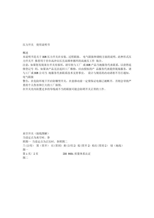
真空开关(接线图解)
当设定点为真空时,参
照图一当设定点为正压时,参照图二
兰(公用)黑(常开)红(常闭) 黄(公用2) 棕(常开2) 桔红(常闭2)绿(地线)
图一
第1页/ 2页 ISO 9001质量体系认证
图二。
SOR压力开关样本
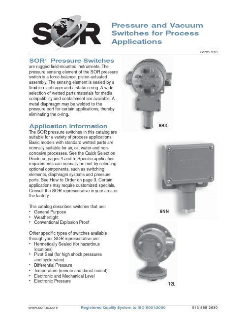
Pressure and Vacuum Switches for Process ApplicationsForm 216SOR ® Pressure Switchesare rugged fi eld-mounted instruments. Thepressure sensing element of the SOR pressure switch is a force-balance, piston-actuated assembly. The sensing element is sealed by a fl exible diaphragm and a static o-ring. A wide selection of wetted parts materials for media compatibility and containment are available. A metal diaphragm may be welded to thepressure port for certain applications, thereby eliminating the o-ring.Application InformationThe SOR pressure switches in this catalog are suitable for a variety of process applications. Basic models with standard wetted parts are normally suitable for air, oil, water and non-corrosive processes. See the Quick Selection Guide on pages 4 and 5. Specifi c application requirements can normally be met by selecting optional components, such as switching elements, diaphragm systems and pressure ports. See How to Order on page 3. Certain applications may require customized specials. Consult the SOR representative in your area or the factory.This catalog describes switches that are: • General Purpose • Weathertight• Conventional Explosion ProofOther specifi c types of switches available through your SOR representative are:• Hermetically Sealed (for hazardous locations)• Pivot Seal (for high shock pressuresand cycle rates)• Differential Pressure• Temperature (remote and direct mount)• Electronic and Mechanical Level • Electronic Pressure12L6B36NNFeatures SwitchesComplete Product LineStandard models and customized specials cover pressure range from30 inches Hg VAC to 4000 psi.Robust ConstructionRugged, high-cycle rate tolerance, long life, not critical to vibration, high overrange and proof pressures, excellent corrosionresistance to hostile environments. Instrument QualityHigh resolution of Set Points, high repeatability, narrow dead band,negligible temperature effect.Wetted PartsWide selection materials, process connection confi gurations and sizes.Optional “fi re-safe” pressure sensor.Snap-Action Electrical SwitchingWide selection UL Listed and CSA Certifi ed switching elements for ACand DC service. Optional “hermeticallysealed” capsule for hazardous and hostile environments.Field AdjustableSelf-locking adjustment, no special tools required. No-charge factory calibration.Cost EffectiveSimple and fast installation without special tools, long service life, norequired periodic service or spareparts.UL Listed, CSA Certifi ed, ATEXCertifi ed, FM, JIS/RIIS Approved ModelsMeets most code and customer requirements.Built-In QualityRigid quality standards maintained from raw material to fi nished product.ServiceFactory sales engineers and area SOR representatives provideeffective and prompt worldwideservice.DeliveryRoutine shipments 7 to 10 working days. Emergency shipments via sameday air.Warranty3 years from date of manufacture.Quick Selection GuideBasic SOR pressure switches with standard wetted parts are normally suitable for air, oil, water and non-corrosive processes. The Quick Selection Guide on pages 4 and 5 shows these basic SOR pressure and vacuum switches. Corrosive service and particular customer requirements may require optional components. Refer to How to Order section below to build a customized model number or the dedicated page to locate optional components, such as switching elements, diaphragm systems, pressure ports and accessories. Each position in the model number, except Accessories, must have a designator.Design and specifi cations are subject to change without notice. For latest revision, see .6NN-K5-M4-C2A-YYModel Number SystemDiaphragmHousingPistonSwitching Element Range SpringPressure PortAccessoriesApplicationsSOR pressure switches in this catalog are suitable for a wide variety of continuous pressure applications. Specifi c application requirements can normally be met by selecting optional components, such as, switching elements, diaphragm systems and pressure ports. Certain applications may require customized specials. Consult the SOR representative in your area or the factory.How to OrderInformation and data in this catalog are formatted to provide a convenient guide to assistinstrument engineers, plant engineers and end users in selecting pressure switches for their unique applications.Steps 1 through 5 are required. Step 6 is optional. Orders must have complete Model Numbers, i.e. each component must have a designator.Step 1: Select Piston-Spring adjustable range/Set Point from Specifi cations (pages 7 & 8). (Piston/Spring combination determines adjustable range.)Step 2: Select Housing for type of pressure switch and service (page 9).Step 3: Select electrical Switching Element for electrical service (pages 10 & 11).Step 4: Select Diaphragm and O-Ring for process compatibility and containment (pages 12 & 13).Step 5:Select Pressure Port for process compatibility and connection (page 14).Step 6: Select Accessories required for service (page 16).How to OrderSwitchesExplosion ProofWeathertightBasic SOR pressure switches with standard wetted parts are normally suitable for air, oil, waterand non-corrosive processes. Corrosive service and particular customer requirements may require optional components. Refer to How to Order on page 3 to locate optional components, such as, housing, switching elements, diaphragm systems, pressure ports and accessories. Each position in the model number, except Accessories, must have a designator.WeathertightExplosion ProofStandard Construction• Housing: NN - aluminum; L - cast iron• Switching Element: SPDT; N - 10 amps @ 250 VAC; K - 15 amps @ 250 VAC• Diaphragm & O-ring: N4 - primary (wetted)diaphragm, TCP; o-ring (wetted) Buna-N• Pressure Port: 1/4” NPT(F); B1A - aluminum; F1A - carbon steelNotes1. See balance of catalog for construction options.2. Dead band values are expressed as typical expected at mid-range for a particular model number. See Dead Band Considerations on page 8.3. Design and specifi cations subject to changewithout notice. For latest revision, see.Standard Construction• Housing: NN - aluminum; L - cast iron• Switching Element: SPDT; K - 15 amps @ 250 VAC• Diaphragm & O-ring: N4 - primary (wetted)diaphragm, TCP; o-ring (wetted) Buna-N• Pressure Port: 1/4” NPT(F); B1A - aluminum; F1A - carbon steelNotes1. See balance of catalog for construction options.2. Dead band values are expressed as typical expected at mid-range for a particular model number. See Dead Band Considerations on page 8.3. Design and specifi cations subject to change without notice. For latest revision, see .WeathertightExplosion ProofExplosion ProofWeathertightStandard Construction• Housing: NN - aluminum; L - cast iron• Switching Element: SPDT; K - 15 amps @ 250 VAC • Diaphragm & O-ring: N4 - primary (wetted) diaphragm, TCP; o-ring (wetted) Buna-N. Piston 56 primary (wetted) diaphragm, 316SS.• Pressure Port: 1/4” NPT(F); B1A - aluminum; F1A - carbon steelNotes1. See balance of catalog for construction options.2. Dead band values are expressed as typical expected at mid-range for a particular model number. See Dead Band Considerations on page 8.3. Design and specifi cations subject to change without notice. For latest revision, see .Quick Selection Guide - VacuumPressure SwitchA bi-stable electromechanical device that actuates/deactuates one or more electrical switching element(s) at a predetermined discrete pressure/vacuum (Set Point) upon rising or falling pressure/vacuum.Adjustable RangeThe span of pressure between upper and lower limits within which the pressure switch can be adjusted to actuate/deactuate. It is expressed for increasing pressure.Set PointThat discrete pressure at which the pressure switch is adjusted to actuate/deactuate on rising or falling pressure. It must fall within the adjustable range and be called out as increasing or decreasing pressure.Dead BandThe difference in pressure between theincreasing Set Point and the decreasing Set Point. It is expressed as typical, which is an average with the increasing Set Point at mid-range for a pressure switch with the standard K switching element. It is normally fi xed (non-adjustable).Fire-SafeThe ability of a welded seal pressure sensor to contain the process at elevated temperatures up to 1200°F at the rated overrange pressure, unsupported by the body of the pressure switch.Hermetically SealedA welded steel capsule with glass-to-metal, factory-sealed electrical leads that isolates the electrical switching element(s) from the environment.OverrangeThe maximum input pressure that can be continuously applied to the pressure switch without causing permanent change of Set Point, leakage or material failure.SwitchesGlossary of T ermsSOR recognizes that there is no industry convention with respect to terminology and defi nitions pertinent to pressure switches. This glossary applies to SOR pressure switches.Proof PressureThe maximum input pressure that can be continuously applied to the pressure switch without causing leakage or catastrophic material failure. Permanent change of Set Points may occur, or the device may be rendered inoperative.RepeatabilityThe ability of a pressure switch to successively operate at a Set Point that is approached from a starting point in the same direction and returns to the starting point over three consecutive cycles to establish a pressure profi le.Repeatability on SOR switches will be smaller than 1% of full scale per ISA/ANSI S51.1. SPDT Switching ElementSingle-Pole, Double Throw (SPDT) has three connections: C — Common, NO — Normally Open and NC — Normally Closed, whichallows the switching element to be electrically connected to the circuit in either NO or NC state.DPDT Switching ElementDPDT is two synchronized SPDT switching elements which actuate together at increasing Set Point and deactuate together at decreasing Set Point. Discrete SPDT switching elements allow two independent circuits to be switched; i.e., one AC and one DC.The synchronization linkage is factory set, and is not fi eld adjustable. Synchronization is verifi ed by connecting test lamps to the switching elements and observing them go “On” simultaneously at actuation and “Off” simultaneously at deactuation.6NN-K5-M4-C2A-YY This table is a listing of piston-spring combinations and the corresponding adjustable ranges, dead bands, overrange and proof pressures. Adjustable range is expressed for increasing pressure; the Set Point must be within the adjustable range. Dead band is expressed as typical. See Dead Band Considerations on page 8.1. Dead band values are expressed as typicalexpected at mid-range with the standard Kswitching element assembly installed. Whenoptional switching elements are specifi ed,corresponding dead band multipliers shownon pages 8 and 10 must be applied.2. The 12/66 piston/spring combination isavailable with the N switching element only.3. Adjustable range becomes 10 to 45 in. wcwhenever switching elements other than K, KA,W or D are used.4. Special ranges may be possible. Consult thefactory or the SOR representative in your area. 5. Diaphragms may have an additional effect ondead band. See page 13, Note 9.6. Diaphragm life may be limited by using T or Hswitching elements with Numbers 1 and9pistons.7. Metric bar (mbar) values are practicalequivalents of the reference English values; notnecessarily exact mathematical conversions.This data appears on the product nameplatewhen metric engineering units are specifi ed.8. A breather drain (Accessory KK, see page 16)should be specifi ed when low pressureadjustable ranges are used in environmentswith signifi cant ambient temperature changes.9. Filled isolators attached to the pressure switchwill affect dead band.This table is a listing of piston–spring combinations and the corresponding adjustable ranges, dead bands, overrange and proof pressures. SOR vacuum switches are compound; they will operate in either vacuum or pressure modes. Adjustable range is expressed from maximum vacuum decreasing to zero gauge andincreasing to maximum pressure. Dead band is expressed as typical. See dead band considerations below. The Set Point must be within the adjustable range. A vacuum switch is generally better suited than a pressure switch for Set Points very near zero gauge.Notes1. Dead band values are expressed as typical expected at mid-range with the standard K switching element assembly installed. When optional switching elements are specifi ed, corresponding dead band multipliers shown below must be applied.2. Special ranges may be possible. Consult the factory or the SOR representative in your area.3. Diaphragms may have an additional effect on dead band. See page 13, Note 9.4. Metric bar (mbar) values are practical equivalents of the reference English values; not necessarily exact mathematical conversions. This data appears on the product nameplate when metric engineering units are specifi ed.1. Dead band values are expressed as typical expected atmid-adjustable range using the standard K switching element. When optional switching elements are specifi ed, corresponding dead band multipliers must be applied.2. Dead bands are fi xed (non-adjustable), except when T or H switching elements are used.3. Dead band can be adjustable by selecting T or H switching element. (Diaphragm life may be limited when used with Numbers 1 and 9 pistons.)4. Dead band multipliers must be applied to the typical dead band value shown for piston-spring combination in specifi cations, pages 7 and 8, whenever optional switching elements other than K, KA or W are used.5. Dead band can be widened by selecting an optional switching element with a multiplier greater than 1.0. Example: Model 6NN-G5-M4-C2A-YY Typical Dead Band 1.4 psi G-Switching Element multiplier = 3 Corrected Typical Dead Band 1.4 x 3 = 4.2 psi6. See item #9, page7.Dead Band Considerations52NN-K 116-M4-C2A-YYClass II, Group E, F, & G; Divisions 1 *L*S*LC*T A*J4NNN6P3Electrical: 3/4” NPT(F) - Left, Right Material: AluminumSee Agency Listings pages 17 & 18.See Switching Element Groups 1, 2, 3 & 4 below.N3N4RN RBSwitchesStep 2: Housing*BD only available with RN, RT housings.*C micro switch is not available in L, S and TA housings.*CA micro switch only available in PP, NN, N3 and N4 housings.Switches Step 3: Switching Element6NN-K5-M4-C2A-YYCross reference compatibility chart on page 9 to ensure that switching element will fi t in housing. Review notes on page 11 for more details.SwitchesStep 3: Switching Element6NN-K 5-M4-C2A-YYNotes1. Double switching elements have wire leads except when supplied in housings RB, RM, RN, RS, RT, B3, B4, B5, B6 and J4. Terminal blocks are standard in these housings.2. Dead band multipliers must be applied to thetypical dead band fi gures given in the specifi cation tables on pages 7 and 8.3. Switching element ambient temperature limits:-65 to 400o F (-54 to 200o C) B, Y, W-65 to 250o F (-54 to 120oC) A, E, & J-40 to 167o F (-40 to 75oC) AF, AG, E F , EG,JF, JG-13 to 158o F (-25 to 70o C) BD-65 to 180o F (-54 to 80o C) All others4. The hermetically sealed switching elementcapsule is ATEX Approved, UL Listed, CSA Certifi ed and SAA Approved as an explosion-proof snap switch according to the following table with conditions and exceptions specifi ed in Note 3.5. Switching elements W, & Y have Elgiloy springs.6. Certain switching elements can handle greater voltage and/or amperage. Consult the factory should your requirements exceed catalog values. All switching elements above except BD are UL Recognized and CSA Certifi ed. The DC current ratings marked with an asterisk (*) are not UL Listed but have been verifi ed by testing and/or experience.7. Ambient temperature is reduced to 200°F (93°C) for J, JJ, A, AA, E, EE, B, BB, Y, YY, & W switching elements when CV accessory is selected.CAUTION: The switching element assemblyhas been precisely positioned in the housing at the factory for optimum performance. Any inadvertent movement or replacement in the fi eld will degrade performance, could render the device inoperative, and can void the warranty unless factory authorized proceduresare followed.Notes Array1. N4 diaphragm system is standard, but requiresa designator in the model number. It is normallysuitable for air, oil, water and noncorrosiveprocesses. M2 diaphragm system is standardon Number 56 vacuum switches. (See notes10 & 13.)2. U7 designates a welded fl ush-type diaphragm.Available only in 1” NPT(M) 316SS onNumbers 5 & 6 pistons with K switchingelement. See page 15.3. U8 designates the welded fi re-safe diaphragmsystem. 316SS is stocked. Not available onNumber 1 piston or vacuum switches.Example: U8-C2A is a 316SS fi re-safe weldeddiaphragm system. See page 15.4. U9 designates a welded diaphragm system.Not available on vacuum switches.Example: U9-A1A is a Monel weldeddiaphragm system. See page 15.5. Other diaphragm and o-ring combinations maybe available. Consult the factory or the SORrepresentative in your area for more information.6. Wetted parts have been selected asrepresenting the most suitable commerciallyavailable material for use in the service intended.However, they do not constitute a guaranteeagainst corrosion or permeation, since processes vary from plant to plant and concentration ofharmful fl uids, gases or solids vary from time totime in a given process. Empirical experienceby users should be the fi nal guide. Alternatematerials are generally available.(Continued on page 13.)7. N3 diaphragm system utilizes a durableback-up diaphragm for high cycle-rate, highshock applications where Buna-N and TCP are compatible with the process. Consult factory if process temperatures are well below freezing.8. This table shows allowable minimum andmaximum temperatures for o-rings. Consult the factory for temperatures down to –65°F onfi re- safe and welded metal diaphragmsystems.9. Dead bands are slightly higher when usingH, J, N3, N6, U or W series diaphragmoptions. Consult the factory.10. Diaphragm systems N1, N3, N4, N5, N6, N7,N8, P1, R1, S1, S2, W2, W4, W5, W6, Y1,U8, U9 are not available on Number 56vacuumswitches.11. M9 diaphragm system is suggested for steamapplications up to 400°F.12. If Kalrez, EPR or Viton is selected for hightemperature process media or ambienttemperature requirements, the A, B, E, J, W or Y switching elements are suggested withreference to the table in Note 3, page 11. 13. Only diaphragm systems N1, N4, N5, N7, N8and P1 are available on the 12-66 piston-springcombination.SwitchesStep 5: Pressure Port6NN-K5-M4-C2A -YYNotes1. Select designators for material and connection size. Large bold-face letters denote those items generally available from stock. Small light-face letters denote items with limited stock and possible long delivery.2. 1/4” and 1/2” tapered BSP(F) pressure ports are available. Consult factory.3. Combinations are possible when a particular connection size is not available for the range (piston/spring) desired. For example, if 2” NPT(F) is desired for a Number 4 piston, the Number 12 pressure port can be supplied. The piston would be designated as Number 124 and the overrange and proof pressures for Number 12 apply. Note: 124, 125 and 126 are the only available combinations.4. Many other materials such as PVC, Kynar, etc., are available. Denote materials not shown by specifying an X followed by the required connection size, and describe the material.Examples:X2A = PVC pressure port with 1/2” NPT(F) connection.X1A = Titanium pressure port with 1/4” NPT(F) connection.Non-metal pressure ports generally reduce proof pressure and may reduce overrange pressure. The pressure port material may limit the process temperature. Delivery may be longer than normal.5. Raised-face and fl at-face fl anges to match ASA 150 and ASA 300 lb. in commercially available materials can be supplied on Series 12 and 4 pistons by adding an X suffi x to the model numbers and specifying “X - (size) inch (material) (raised- or fl at-) face fl ange to match ASA (rating) lb.”6. Brass not available on Piston Numbers 9 and 1.7. 1/4” NPT(F) Flushing Port standard on C6A pressure ports.*C4A only available with Pistons 5 & 6 when U7 diaphragm is specifi ed. See page 15.See next page for presentation of welded diaphragm and FM Approved fire-safe systems.Pressure and Vacuum SwitchesWelded Diaphragm & Fire-Safe SystemsFactory Mutual System Approved - U.S Patent Number 4,438,305Two-inch Pressure PortThe wide pressure port minimizes the possibility of clogging when the process media is sludgy or viscous. See page 20 for dimensions. A 2” NPT(F) pressure port with a 1/4” NPT(F) fl ushing port can be supplied with a welded diaphragm, or with a conventional diaphragm and o-ring combination.ConnectionPiston ShaftDiaphragmSwitches Step 6: Accessories6NN-K5-M4-C2A-YY*Consult the factory for materials other than 316/316L.CSATIISATEXBASEEFASOR Pressure Switches in this catalog may be specifi ed with manual reset electrical switching elements D or M. D actuates automatically on increasing pressure. M actuates automatically on decreasing pressure. Depress the button to manually reset. Housings must be RB (weathertight) or S (explosion proof) because of the requirement of a hub for the manual reset assembly. Refer to page 3 for How to Order instructions.Shipping WeightsManual Reset ButtonRB - Weathertight S - Explosion ProofSwitchesManual ResetActual shipping weights may vary from the charted values because of product material, confi guration and packaging requirements.NotePK Pipe Kit adds approximately 1.5 lbs. (0.7 kgs). TB Junction box adds approximately 5 lbs (2.25 kgs).Dimensions in this catalog are for reference only. They may be changed without notice. Contact the factory for certifi ed drawings for a particular model number.Notes 1. Dimensions in this catalog are expressed as millimeters over inches (Linear = mm/in.). 2. Dimensions marked with an asterisk (*) on housing dimension drawings (pages 20 through 31) vary with respect to process connection size. The chart below lists these dimension variances. 3. Electrical Connection Size: 3/4” NPT(F) standard. 1/2” NPT(F), 1/2” NPT(M), M20 x 1.5, PG 13.5, PF 3/4” optional. Consult the factory for compatibility with selected housing or agencylisting.DimensionsSwitchesDimensionsDimensions in this catalog are for reference only. They may be changed without notice. Contact the factory for certifi ed drawings for a particular model number.Wide Pressure Port: C6ASee description on page 15.Pipe Mounting Kit: PKDrawing # 0091354Drawing # 0090300Drawing # 0091353Junction Box with T erminalBlock:TBDimensions in this catalog are for reference only. They may be changed without notice. Contact the factory for certifi ed drawings for a particular model number.Weathertight - NEMA 4, 4X, IP65Housing PP, P3 and PF are General Purpose.(Cover gasket is not installed.)Dimensions in this catalog are for reference only. They may be changed without notice. Contact the factory for certifi ed drawings for a particular model number.Piston Numbers 5, 6, 1, 9, 56Dimensions in this catalog are for reference only. They may be changed without notice. Contact the factory for certifi ed drawings for a particular model number.Open BracketDesignators: H3Piston Numbers 5, 6, 9, 1, 56Drawing # 0090027Dimensions in this catalog are for reference only. They may be changed without notice. Contact the factory for certifi ed drawings for a particular model number.Weathertight - NEMA 4, 4X, IP65Designators: N6Piston Numbers Drawing 0090020Dimensions in this catalog are for reference only. They may be changed without notice. Contact the factory for certifi ed drawings for a particular model number.Conventional Explosion ProofDimensions in this catalog are for reference only. They may be changed without notice. Contact the factory for certifi ed drawings for a particular model number.Conventional Explosion ProofDesignators: SPiston Numbers 5, 6, 9, 1, 56Drawing # 0090147Dimensions in this catalog are for reference only. They may be changed without notice. Contact the factory for certifi ed drawings for a particular model number.Conventional Explosion ProofPiston Numbers 5, 6, 9, 1, 56SC shown. LC identical except right-handelectrical connection only.Dimensions in this catalog are for reference only. They may be changed without notice. Contact the factory for certifi ed drawings for a particular model number.Conventional Explosion ProofPiston Numbers 5, 6, 9, 1, 56Dimensions in this catalog are for reference only. They may be changed without notice. Contact the factory for certifi ed drawings for a particular model number.Explosion ProofDimensions in this catalog are for reference only. They may be changed without notice. Contact the factory for certifi ed drawings for a particular model number.Weathertight - NEMA 4, 4X, IP65Drawing # 0090271Designators: RB Manual ResetPiston Numbers 5, 6, 1, 9, 56Pressure and VacuumSwitches Dimensions Dimensions in this catalog are for reference only. They may be changed without notice. Contact the factory for certifi ed drawings for a particular model number.Conventional Explosion ProofDrawing # 0090169Designators: S Manual ResetPiston Numbers 5, 6, 1, 9, 56*Refer to Dimensions table on page 19 for changes in length due to process connection size, including A dimension.Registered Quality System to ISO 9001:200032/32Form 913-888-2630echOsonix Level TransmittersT emperature SwitchesP r e s s u r eFlowLevelLevel SwitchesFlow SwitchesPressure SwitchesSOR ®offers a full line of commercial-grade process instruments.TemperatureRegistered Quality System to ISO 9001:2000Form 216 (04.08) ©2008 SOR Inc.We Deliver Quality On TimeSOR Europe, Ltd.Star RoadPartridge Green, Sussex RH13 8RA, United Kingdom Phone +44-140-371-1331Fax +44-140-371-0177sales@SOR - ChinaRoom 903, No. 10 Building Wan Da PlazaNo. 93 Jian Guo Road Chao Yang District Beijing, China 100022Phone +86 (10) 5820 8767Fax +86 (10) 5820 8770SOR Inc.14685 West 105th Street Lenexa, Kansas 66215Phone 913-888-2630Toll Free 800-676-6794Fax 913-888-0767Process Instrumentation。
压力开关规格书
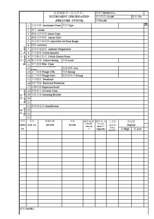
1 仪表名称 Instrument Name 类型 Type 2 3 4 5 6 7 8 9 10 11 12 13 14 15 16 17 18 19 20 21 22 23 24 25 型号 Model 测量元件类型 Senser Type 测量元件材质 Sensor Mat'l 设定值可调范围 Adjustable Set Point Range 精度 Accuracy 适用环境温度 Ambient Temperature 开关数量 Switch Quantity 开关触点形式 Switch Contact Form 触点容量 Contact Rating 负载 Load 电气连接 Elec. Conn. 过程连接形式 Process Conn. 连接规格 Size 法兰标准 Flange STR. 等级 Rating 法兰材质 Flange Mat'l 密封面形式 Facing 不灵敏区 Deadband 防护等级 Enclosure Protection 防爆等级 Explosion Proof 转换接头 Coverter Conn. 安装支架 Mounting Bracket
档案号PROJECT No: 设计阶段 STAGE: 页数PAGE:
版本 FA
REV
附件 Accessories 其他 Miscell
压力开关 Pressure Switch
推荐制造商 Manufacturer
序号 No.
位号
检测位置 SEVICE
介质 FLUID
操作温度 操作压力
OPER. TEMP OPER. PRESS
工艺管 道材质
sor压力开关工作原理
sor压力开关工作原理
Sor压力开关(也称为静压力开关)是一种用于监测液体或气体压力的开关装置。
它的工作原理基于压力的变化来控制电气电路的开闭。
当压力施加在Sor压力开关上时,内部的感应元件(通常是一个弹簧或膜片)会受到压力的影响而发生形变。
这种形变会导致感应元件内部的接点发生移动,从而改变开关的状态。
当压力达到设定值时,开关会闭合或打开,从而触发相应的电气信号。
Sor压力开关通常用于控制液体或气体系统中的压力,以确保系统在安全范围内运行。
例如,当压力超过设定值时,Sor压力开关可以自动切断供应液体或气体的流动,以防止系统过载或损坏。
它还可以用于监测液体或气体的压力变化,并触发相应的报警或控制信号。
总的来说,Sor压力开关的工作原理是基于压力的变化来控制内部接点的状态,从而实现对液体或气体压力的监测和控制。
这种设备在工业自动化和流体控制系统中起着重要作用,保障了系统的安全运行和稳定性。
SOR_NN系列_压力开关_差压开关
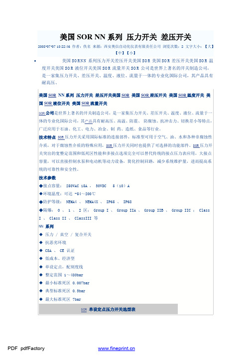
美国SOR NN系列压力开关差压开关2008-07-07 10:22:46 作者:佚名来源:西安奥信自动化仪表有限责任公司浏览次数:2 文字大小:【大】【中】【小】•美国SORNN系列压力开关差压开关美国SOR美国SOR差压开关美国SOR温度开关美国SOR液位开关美国SOR流量开关SOR公司是世界上著名的开关制造公司,是一家集压力开关、差压开关、温度、液位、流量于一体的专业化国际公司,其产品具有耐高压、美国SOR NN系列压力开关差压开关美国SOR美国SOR差压开关美国SOR温度开关美国SOR液位开关美国SOR流量开关SOR公司是世界上著名的开关制造公司,是一家集压力开关、差压开关、温度、液位、流量于一体的专业化国际公司,其产品具有耐高压、高温、防震、防腐蚀、抗冲击力、切换差小等特点,广泛应用于石油、化工、电力、冶金、制药、造纸、食品等行业。
技术特点SOR压力开关采用国际标准的连接部件,标准型可用于空气、油、水和各种非腐蚀性介质,对于腐蚀性介质的特殊应用,SOR压力开关同时也提供了可选择的功能部件。
SOR压力开关突出的宽整定范围和低死区性能和多接点选项完全可以替代传统的接点压力表应用,大接点容量,可以直接控制水泵和电动机等动力设备,简化控制回路,减少系统维护量,进而提高系统的可靠性和安全性。
技术参数◆接点容量: 250VAC 15A , 30VDC 5(10)A◆环境温度:可达 -54~200℃◆防护等级: NEMA4 、 NEMA4X 、 IP65 、 IP68◆隔爆: 0 、 1 、 2 区; Group I 、 Group IIA 、 Group IIB 、 Group IIC ; ClassI 、 Class II 、 ClassIII 等NN 系列◆压力 / 真空 / 复合开关◆抗恶劣环境◆ CSA 、 CE 认证◆低成本、经济型◆单设定点,配刻度线◆整定范围 1~480bar◆最小标准死区 0.007bar◆典型标准死区 0.3bar◆最大标准死区 7barSOR单设定点压力开关选型表型号设定值范围kg/cm2回程差kg/cm2防爆产品型号9NN-K4-N4-F1A 7.03-35.15 0.37 9L-K4-N4-F1A9NN-K5-N4-F1A 14.06-70.31 0.65 9L-K5-N4-F1A9NN-K45-N4-F1A 14.06-123.04 1.05 9L-K45-N4-F1A最大承受压力 175.77 kg/cm2 ;出厂实验压力 421.85kg/cm26NN-K2-N4-F1A 0.49-2.11 0.046L-K2-N4-F1A6NN-K3-N4-F1A 0.84-7.03 0.066L-K3-N4-F1A6NN-K5-N4-F1A 1.41-12.66 0.106L-K5-N4-F1A6NN-K45-N4-F1A 1.76-19.33 0.136L-K45-N4-F1A最大承受压力 105.46 kg/cm2 ;出厂实验压力 175.77kg/cm2SOR压力开关采用国际标准的连接部件,标准型可用于空气、油、水和各种非腐蚀性介质,对于腐蚀性介质的特殊应用,SOR压力开关同时也提供了可选择的功能部件。
双设定压力开关中文说明书

注意:超程距离已在出厂前预先设定,也就是说,为了达到最佳的性能,开关元件组合已精确地在外壳内定 位。通常在现场不必再行调节。如果有必要进行调节,则必须严格地遵循制造厂批准的步骤。任何在现场随
便的移动或更换可能会降低性能、使担保作废并可能使该装置失效。
校准
a. 拆除外壳的盖子。 b. 若要提高1号(左侧)开关元件起动时的设定值,则用3/4英寸开口扳手以顺时针方向转动六角调节螺母。 c. 调节时越过调节螺母的顶部观察外壳内壁上的校准刻度,即可达到近似的设定值。可用一1/4% 的外接压力
其压力传感元件是一对力平衡式、活塞驱动的组合 件,通过弹性膜片和静态密封O形环予以密封。此结 构中唯有压力接口、两套膜片和O形环传感组合件是 接触介质的部件。
重要:务必拧紧和固定该工艺接头,使压力开关上所 承受的任何弯曲和扭曲力量均减小到最低限度。切勿 将压力接口从本体上松开, 因为这可能会造成泄漏或
安装
185.7 * 7.31
70.4 * 2.77
高低压双点系列压力开关可用适当的螺栓固定在隔 墙、仪表盘或管架支柱上。当在不规则或不平整表面 上安装压力开关时,先要在外壳和安装面之间的螺栓 上套上橡胶垫圈。
单位= mm
in.
注意:若不在外壳和安装面之间放置橡胶垫圈,就可 能在外壳上产生扭力,从而导致开关的假动作,或使 该开关失效。
不推荐采用光依靠工艺接口或电气接口的安装方式。
*
251.2 9.89
9.7 .38
直径为9/32 的固定孔
57.2 (通常2个)
114.3 2.25 4.50
工艺接头
V1 全天候密封型
138.9 5.47 69.6
2.74
电气接头
3/4 NPT(F) (制造厂密封
索尔SOR压力传感器选型资料(中文版)

聆听机械微米级专业的判断一个帕斯卡的反应,我们也会告诉您我们一直在努力追求微帕自控的力量SOR索尔压力开关SOR公司(中文名称索尔公司)成立于1946年,是世界上唯一一家集生产各类机械及电子压力、差压、温度、流量、液位开关及变送器于一体的专业化国际公司,总部位于美国肯萨斯州州府,现有员工300人,其压力开关类产品产量位居世界第一。
压力开关产品主要采用静态O型圈密封的活塞-弹簧-膜片组合式结构,具有抗震、抗过压能力强,测量范围广且回差小、使用寿命长等特点。
其生产的高静压低差压开关是世界上独一无二的。
其核级压力及差压开关是世界上不多的取得IEEE认证的产品。
SOR的机械液位开关全部满足ANSIB31.1和B31.3国际电力和石化行业压力容器标准,包括机械式浮球及沉筒两类,其独特的分级冷凝球降温措施能够很好地保证液位开关的开关单元部分免受高温蒸汽的影响,可以可靠地应用于高温工况,越来越受到客户的青睐。
除机械类产品外,SOR的电子产品种类也是非常丰富的,包括热差式流量开关、非接触式超声波变送器、接触式超声波开关,射频导纳开关及变送器、以及集开关、变送器、实时显示三位一体的SGT,该仪表不仅有实时压力显示、独立的开关量输出,而且有4~20毫安模拟量输出。
非接触式超声波变送器具有高能量、低频率、自动增益调节三大特点使其能够应用于诸如碳黑、干灰、啤酒、石膏等高粉尘、高泡沫及高雾气的复杂环境中,帮助很多用户解决了多年来用其他超声波产品甚至是雷达产品都解决不了的难题。
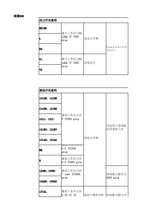
压力控制器(压力计)NN²最大工作压力30 inHg 到 7000 psig ²0.25mm活塞行程,使用寿命长²设定点可调²10amps@250VAC²CSA, CE²NEMA 4, 4X, IP65RN ²最大工作压力30 inHg 到 7000 psig ²0.25mm活塞行程,使用寿命长²设定点可调²10amps@250VAC>²CSA, CE NEMA 4, 4X, IP65L ²最大工作压力30 inHg 到 7000 psig²0.25mm活塞行程,使用寿命长²设定点可调²10amps@250VAC²CSA, CE UL: Class I, Group C, Div. 1B3²最大工作压力30 inHg 到 7000 psig²0.25mm活塞行程,使用寿命长²设定点可调²10amps@250VAC²CSA, CE UL/CSA: Class I, Group B, Div. 1; ATEX: Eex d IIC T6V1²双设定点²最大工作压力30 inHg 到 4000 psig ²0.25mm活塞行程,使用寿命长²设定点可调²10amps@250VAC CSA, CEV2²双设定点²最大工作压力30 inHg 到 4000 psig²0.25mm活塞行程,使用寿命长²设定点可调²10amps@250VAC UL/CSA: Class I, Group A, Div. 1; SnapSw: UL/CSA, ATEX, SAA差压控制器(差压计)101NN,121NN ²最高工作压力从 3 到500 psig²设定点可调²可适用于系统静压突变的工况²15amps@250VAC²CSA, CE ²NEMA 4, 4X, IP65101RN,121RN ²最高工作压力从 3 到500 psig²设定点可调²系统最大静压为1000 psig²可适用于系统静压突变的工况²15amps@250VAC²CSA, CE²NEMA 4, 4X, IP65101L,121L ²最高工作压力从 3 到500 psig²设定点可调²系统最大静压为1000 psig²可适用于系统静压突变的工况²15amps@250VAC²CSA, CE²UL: Class I, Group C, Div. 1101B3,121B3²最高工作压力从 3 到500 psig²设定点可调²系统最大静压为1000 psig²可适用于系统静压突变的工况²15amps@250VAC²CSA, CE²UL/CSA: Class I, Group B, Div. 1; ATEX: Eex d IIC T6101AG,121AG ²最高工作压力从 3 到500 psig²设定点可调²系统最大静压为1000 psig²可适用于系统静压突变的工况²15amps@250VAC²CSA, CE ²UL/CSA: Class I, Group A, Div. 1; ATEX: Eex d IIC; SnapSw:UL/CSA, ATEX, SAARB²最高工作压力从 0.5 到1000 psig²设定点可调 r²可适用于系统静压突变的工况²CSA, CES ²最高工作压力从 0.5 到500 psig²设定点可调²可适用于系统静压突变的工况²UL: Class I, Group C, Div. 1102W1,103W1²设定点可调²最高工作压力从 7 inwc 到2500 psig²系统最大静压为3000 psig²不锈钢外壳²CSA, CE|液位控制器(液位计)100 系列,741-743,801,802²高温环境,温度从 -65°F 到 1000°F²最大工作压力为128bar²控制器单元为不锈钢或者高温陶瓷,抗高温、抗腐蚀²干净/含有杂质液体²最小额定电流为3A@ 220VAC²全系列为ANSI/ASME 标准²所有材质通过ASTM 等级的材料认证 ²UL, CSA, ATEX, SAA ²带腔体侧装200 系列,740-803²高温环境,温度从 -65°F 到 1000°F²最大工作压力为690bar²控制器单元为不锈钢或者高温陶瓷,抗高温、抗腐蚀²干净/含有杂质液体²最小额定电流为3A@ 220VAC²全系列为ANSI/ASME 标准 ²所有材质通过ASTM 等级的材料认证²UL, CSA, ATEX, SAA²带腔体侧装700 系列,730-750²高温环境,温度从 -65°F 到 1000°F²最大工作压力为128bar²控制器单元为不锈钢或者高温陶瓷,抗高温、抗腐蚀²干净/含有杂质液体²全系列为ANSI/ASME 标准²所有材质通过ASTM 等级的材料认证²UL, CSA, ATEX, SAA 顶装300系列²高温环境,温度从 -65°F 到 1000°F²最大工作压力为128bar²控制器单元为不锈钢或者高温陶瓷,抗高温、抗腐蚀²干净/含有杂质液体²全系列为ANSI/ASME 标准²所有材质通过ASTM 等级的材料认证²UL, CSA, ATEX, SAA 顶装108, 208 系列²高温环境,温度从 -65°F 到 1000°F²最大工作压力为690bar²控制器单元为不锈钢或者高温陶瓷,抗高温、抗腐蚀²干净/含有杂质液体²最小额定电流为3A@ 220VAC²全系列为ANSI/ASME 标准 ²所有材质通过ASTM 等级的材料认证²UL, CSA, ATEX, SAA 带腔体侧装1500 系列,1710²最大工作压力为1500 psi, 温度从 -40°F 到 400°F²所有材质通过ASTM 等级的材料认证²CSA温度控制器(温度计)NN ²工作温度从 -50° 到 1000° F²设定点可调²整体安装或分体安装²可选316SS 材质保护套管²316SS 材质探头 ²CSA, CERN²工作温度从-50° 到 1000° F²设定点可调²整体安装或分体安装²316SS 材质保护套管连接²316SS 材质探头 ²CSA, CEL ²工作温度从 -50° 到 1000° F²设定点可调²整体安装或分体安装²316SS 材质保护套管连接²316SS 材质探头 ²UL: Class I, Group C, Div. 1B3²工作温度从 -50° 到 1000° F²设定点可调²整体安装或分体安装²316SS 材质保护套管连接²316SS 材质探头 ²UL/CSA: Class I, Group B, Div. 1; ATEX: EEx d IIC射频导纳651单点RF 控制器²可用作报警器或指示器²不受探头上的工艺物料挂料的影响²经济性好的单点式检测仪表²可用于12VDC 供电²经FM (工厂互助保险公司)认证,并经CSA (加拿大标准协会)认证和CENELEC (欧洲电工技术标准化委员会)认证可应用于危险性工作地点²可在现场选择的故障自动保护功能²环境温度范围-40~71℃²重复精度0.5%²外壳防护等级NEMA 4X 和IP65681单点RF 控制器(具备自检功能)²提供单点控制器功能²通过连续性的自我测试(自检)对开关的运行进行检查。
SOR压力开关(中文)
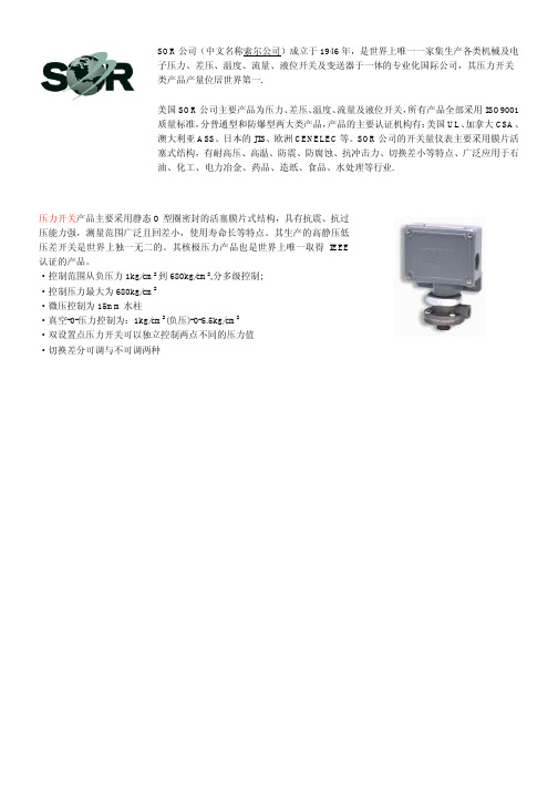
压力开关产品主要采用静态O型圈密封的活塞膜片式结构,具有抗震、抗过压能力强,测量范围广泛且回差小,使用寿命长等特点。
其生产的高静压低压差开关是世界上独一无二的。
其核极压力产品也是世界上唯一取得IEEE 认证的产品。
·控制范围从负压力1kg/cm2到680kg/cm2,分多级控制;
·控制压力最大为680kg/cm2
·微压控制为15mm水柱
·真空-0-压力控制为:1kg/cm2(负压)-0-5.5kg/cm2
·双设置点压力开关可以独立控制两点不同的压力值
·切换差分可调与不可调两种
SOR公司(中文名称索尔公司)成立于1946年,是世界上唯一一家集生产各类机械及电子压力、差压、温度、流量、液位开关及变送器于一体的专业化国际公司,其压力开关类产品产量位居世界第一.
美国SOR公司主要产品为压力、差压、温度、流量及液位开关,所有产品全部采用ISO9001质量标准,分普通型和防爆型两大类产品,产品的主要认证机构有:美国UL、加拿大CSA、澳大利亚ASS、日本的JIS、欧洲CENELEC等。
SOR公司的开关量仪表主要采用膜片活塞式结构,有耐高压、高温、防震、防腐蚀、抗冲击力、切换差小等特点、广泛应用于石油、化工、电力冶金、药品、造纸、食品、水处理等行业.。
美国SOR索尔
SOR索尔差压开关17RB-EE3-N4
SOR索尔差压开关12RM-K614-M4
4NN-K4-N4-B1A
107AL-K40-P1-F1A-RR
压力开关107AL-K40-P1-FOA
压力开关101NN-K3-N4-C1A
压力开关107AL-N12-P1-F1A
54RN-K118-N4-B1A
66V1-K45-N4-B1A-
4RN-J45-N4-C2A-CL
4RN-J5-N4-C2A-CL
6RN-J3-N4-C2A-CL
4RN-J5-M9-C2A-CL
6RN-J2-N4-C2A-CL
4RN-J45-M9-C2A-CL
4B3-K45-N4-C2A-CL
6NN-K5-M4-C2A-TTXX618
12NN-K5-N4-B1A
12NN-K4-N4-C1A
12NN-K614-N4-B1A
6NN-K3-N4-F1A
101NN-EE3-M4-C1A
4NN-K4-M4-C1A-TTX2X371
101NN-EE3-N4-C1A-X373
4NN-5K-M4-CIA-X
5NN-K5-N4-F1A
5NN-K45-N4-F1A
6NN-K2-N4-F1A
6NN-K4-N4-F1A
6NN-K45-N4-F1A
9NN-K4-N4-F1A
9NN-K5-N4-F1A
9NN-K45-N4-F1A
中低压型压力开关
4NN-K2-N4-B1A
4NN-K4-N4-B1A
107EL-EG12-P1-FOA
索尔SOR压力传感器选型资料-资料类

索尔SOR压力传感器选型资料-资料类关键信息项1、压力传感器型号2、测量范围3、精度等级4、输出信号类型5、工作温度范围6、防护等级7、安装方式8、响应时间9、供电电压11 压力传感器型号详细列举索尔 SOR 压力传感器的各种型号,包括但不限于标准型号和特殊定制型号。
对每个型号的特点和适用场景进行简要说明。
111 测量范围明确不同型号压力传感器所能测量的压力范围,例如从最小压力值到最大压力值。
同时说明在超出测量范围时可能出现的情况以及对传感器的潜在损害。
112 精度等级阐述各型号压力传感器的精度等级,如高精度、中精度和低精度等。
解释精度等级对测量结果准确性的影响,并提供相关的精度误差范围数据。
12 输出信号类型介绍索尔 SOR 压力传感器可提供的输出信号类型,如模拟信号(如电压、电流)和数字信号(如 RS485、CAN 总线等)。
说明不同输出信号类型的优缺点和适用的系统接口要求。
121 工作温度范围给出压力传感器正常工作的温度范围,包括最低工作温度和最高工作温度。
强调在极端温度条件下使用时需要采取的防护措施或可能对传感器性能产生的影响。
122 防护等级描述传感器的防护等级,如防水、防尘等方面的能力。
解释防护等级的含义和其在不同恶劣环境中的适用性。
13 安装方式详细说明索尔 SOR 压力传感器的安装方式,如螺纹连接、法兰连接等。
提供安装所需的工具和注意事项,以确保正确安装和稳定运行。
131 响应时间注明压力传感器的响应时间,即从压力变化到输出信号相应变化的时间间隔。
说明响应时间在不同应用场景中的重要性和对系统控制的影响。
132 供电电压明确各型号压力传感器所需的供电电压范围,包括直流和交流电压。
提醒用户在供电时要遵循规定的电压要求,以避免损坏传感器。
2、选型指南基于上述关键信息项,为用户提供选型的指导原则和步骤。
例如,根据测量压力的大小、精度要求、工作环境温度、输出信号需求等因素,如何选择合适的索尔 SOR 压力传感器型号。
SOR
SORSOR公司(中文名称索尔公司)成立于1946年,是世界上唯一一家集生产各类机械及电子压力、差压、温度、流量、液位开关及变送器于一体的专业化国际公司,总部位于美国勘萨斯州州府,现有员工300人,其压力开关类产品产量位居世界第一。
SOR压力开关产品主要采用静态O型圈密封的活塞膜片式结构,具有抗震、抗过压能力强,测量范围广泛且回差小,使用寿命长等特点。
其生产的高静压低压差开关是世界上独一无二的。
其核极压力产品也是世界上唯一取得IEEE认证的产品。
SOR的机械液位开关全部满足ANSIB31.1和B31.3标准,包括机械式浮球及浮筒两类,其独特的分级冷凝球降温措施能够很好地保证液位开关的开关单元部分免受高温蒸汽的影响,可以可靠地应用于高温工况,越来越受到客户的青睐。
除机械类产品外,SOR的电子产品种类也是非常丰富的,包括热差式流量开关,接触式超声波开关,射频导纳开关及变送器,开关与变送器及显示三位一体的SGT以及非接触式超声波变送器。
其生产的非接触式超声波变送器具有高能量、低频率、自动增益调节三大特点使其能够应用于诸如碳黑、干灰、啤酒、石膏等高粉尘、高泡沫及高雾气的复杂环境中,帮助很多用户解决了多年来用其他超声波产品甚至是雷达产品都解决不了的难题。
由于SOR产品的多样性、高质量、良好的售后服务,赢得了客户的大力支持,使其广泛应用于电力、石油天然气、化工、水处理、造纸、冶金等行业,从1997年至今,SOR在中国过程工业尤其是电力行业中,其市场占有率已稳坐第一,并长达五年之久,在中国已经形成了以北京代表处为核心的强大销售及售后服务网络,销售及服务人员遍及全国各省、直辖市和自治区。
美国SOR公司主要产品为压力、差压、温度、流量及液位开关,所有产品全部采用ISO9001质量标准,分普通型和防爆型两大类产品,产品的主要认证机构有:美国UL、加拿大CSA、澳大利亚ASS、日本的JIS、欧洲CENELEC等。
SOR公司的开关量仪表主要采用膜片活塞式结构,有耐高压、高温、防震、防腐蚀、抗冲击力、切换差小等特点、广泛应用于石油、化工、电力冶金、药品、造纸、食品、水处理等行业。
SOR Inc. 101 121 差分压力开关说明书
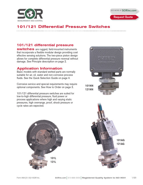
101/121 differential pressure switches are rugged, field-mounted instrumentsthat incorporate a flexible modular design providing cost effective sensing solutions. The two-piece piston design allows for complete differential pressure reversal without damage. See Principle description on page 2.Application InformationBasic models with standard wetted parts are normally suitable for air, oil, water and non-corrosive process fluids. See the Quick Selection Guide on page 4.Corrosive service and special requirements may require optional components. See How to Order on page 3.101/121 differential pressure switches are suited for low-to-high differential pressure, fluid power or process applications where high and varying static pressures, high overrange, proof, shock pressure or cycle rates are expected.101NN 121NN101AG 121AG101L 121L101/121 Differential Pressure SwitchesSEE MORE AT Request QuoteF h = Force, Hi Pressure F l = Force, Lo PressureF s = Force, Range SpringF d = Force, Resultant DifferentialF d = F h - (F l + F s )Process pressure is sensed by a diaphragm-piston combination. Hi-side system pressure acts on the piston to product force F h . It is counteracted by the adjustable range spring force F s and Lo-side system pressure acting on the backside of the piston to produce force F l . The resultant force F d acts on the piston and overcomes the force of the adjustable range spring [F d = F h – (F l + F s )] and moves a shaft that actuates (deactuates) an electrical switching element.AF hF lF sF dNCNOCDifferential Pressure SwitchPrincipleQuick Selection GuideBasic Series 101/121 differential pressure switches with standard wetted parts are normallysuitable for air, oil, water and non-corrosive processes. Refer to the Quick Selection Guide section on page 4. Corrosive service and particular customer requirements may require optionalcomponents. Refer to the How to Order section on this page or the dedicated page to locate optional components, such as: housings, switching elements, diaphragm systems, pressure ports and accessories. Each position in the model number, except Accessories, must have a designator.101NN-K3-N4-C1A-YYModel Number SystemSeriesHousingDiaphragm& O-RingSwitching Element Adjustable RangePressure PortAccessoriesApplicationsThe Series 101/121 differential pressure switches in this catalog are suitable for a wide variety of process and fluid power applications. Specific application requirements can normally be met by selecting optional components, such as, switching elements and diaphragm systems. Certain applications may require customized specials. Consult local representative or the factory.Weathertight, conventional explosion proof and hermetically sealed explosion proof models are presented in this catalog.How to OrderSteps 1 through 5 are required; Step 6 is optional. Orders must have complete model numbers, i.e. each component must have a designator.Order information must include:a) Set Point (increasing or decreasing)b) If decreasing Set Point, state from what greater Set Point is approached c) Normal system (static) pressureStep 1: Select Housing for type of service (pages 5 & 6).Step 2: Select electrical Switching Element for housing and electrical service (pages 6 & 7).Step 3: Select Adjustable Range according to Set Point (page 8).Step 4:Select Diaphragm and O-Ring for process compatibility and containment (page 9).Step 5:Select Pressure Port for process connection (page 9). Step 6: Select Accessories as required for service (page 10).If Agency Listed, Certified or Approved differential pressure switches are required, see page 11 for components that must be specified.Differential Pressure SwitchHow to OrderDifferential Pressure Switch Principle Specify model number from table below.WeathertightNEMA 4, 4X, IP65Hazardous LocationsClass I, Groups C & D;Class II, Groups E, F & G;Divisions 1 & 2Hazardous LocationsClass II, GroupsE, F & G; Divisions 1 & 2See Agency Listings page 11.See Switching Element Groups 1, 2, 3, 4 page 6.See Agency Listings page 11.See Switching Element Groups 1, 2, 3, 4 page 6.Contains UL Listed, CSA Certified, ATEX and SAA Approved Electrical: 1/2” NPT(M)-Top Material: See Switching Element Group 5 page 6.See Switching Element Groups 1, 2, 3, 4 page 6.See Agency Listings page 11.See Switching Element Groups 1, 2, 3, 4 page 6.Open bracket with exposed switchingelement does not meet NEMA 1.See Switching Element Groups 1 & 3 page 6.See Agency Listings page 11.See Switching Element Group 7 page 6.Weathertight —NEMA 4, 4X, IP65Electrical: 3/4” NPT(F)- Right Material: AluminumCover: heavy duty with Viton gasketN4See Agency Listings page 11.See Switching Element Groups 1, 2, 3, 4 page 6.See Switching Element Groups 1 & 3 page 6.RN RM Electrical-RT: 3/4” NPT(F)-Right Electrical-RS: M20 x 1.5-Right Six-place compression type terminal block Material: 316SSRT RSContains UL Listed, CSA Certified and SAA Approved hermetically sealed switching elements. Electrical: 3/4” NPT(F)-TopMaterial: Copper-free** aluminumWeathertight: NEMA 4/4XSee Switching Element Group 6 page 6.Class II, Groups E, F & G; Divisions 1 101NN -K3-N4-C1A-YYSeparate electrical and set point adjustment compartments. WeathertightSix-place compression type terminal blockSee Agency Listings page 11.Class II, Groups E, F & G; Divisions 1 & 2 as an outlet box only.Electrical: 3/4” NPT(F)-Left, Right, TopSix-place compression type terminal block with Optional LL Material: Copper-free** aluminum Class I, Groups A, B, C, D; Class II,See Switching Element Groups 1 & 3 page 6.*B3* Not recommended for direct mount where vibration is expected. Housing should be securely mounted to a flat surface (bulkhead or panel rack) or pipe stanchion. ** Consult the factory.See Switching Element Groups 1 & 3 page 6.See Switching Element Groups 1, 2, 3, 4 page 6.See Switching Element Groups 1 , 3, 7 page 6.See Switching Element Groups 1, 2, 3, 4, 7 page 6.Hazardous Locations — Conventional Explosion ProofATEX and SAA Approved Electrical: 1/2” NPT(M)-TopMaterial: See Switching Element Group 5 page 6.101NN-K3-N4-C1A-YYCross reference compatibility chart above to ensure that switching element will fit in housing.Notes1. AC/DC electrical ratings for switchingelements K, KK, KA, J, JJ, G, GG, A, AA, L, LL, E, EE, C, S, B, BB, Y, YY, W, T, H, D and M are UL Recognized and CSA Certifiedwith conditions and exceptions specified in Note 3.2. The hermetically sealed switching elementcapsule is UL Listed, CSA Certified, ATEXand TestSafe Approved as a snap switch in accordance with the following table withconditions and exceptions specified inNote 3.3. DC electrical ratings are for resistive loadsonly. DC ratings marked with an asterisk (*) are not agency recognized or certified buthave been verified by testing or experience.Switching Element101NN-K3-N4-C1A-YY 4. DPDT switching elements have wire leadsexcept when supplied in housings RN, RT,RM, RS, RB, B3, B4, B5, B6.5. Switching element minimum/maximumambient temperatures:-40 to 167o F (-40 to 75o C) AF, AG, EB,EF, EG, JB,JF, JG, JR, KB -65 to 400o F (-54 to 204o C) B, Y, W-65 to 250o F (-54 to 120o C) A, E, J-65 to 180o F (-54 to 80o C) All others 6. Dead band multipliers must be applied to thetypical dead band figures given in thespecification tables on page 8.7. Switching elements B, W and Y have anElgiloy spring. Experience indicates goodservice in atmospheres with corrosivegases - H2S, ammonia, etc.CAUTION: The switching element assembly has been precisely positioned in the housing at the factory for optimum performance. Any inadver-tent movement or replacement in the field will degrade performance, could render the device inoperative and may void the warranty unless factory authorized procedures are followed.Differential Pressure SwitchAdjustable Range101NN-K 3-N4-C1A-YYThis table lists designators for corresponding adjustable ranges, dead bands, maximum system pressure and maximum differential pressure. Adjustable range is expressed for increasing pressure: the Set Point must be within the adjustable range. Dead band is expressed as typical at mid-range. See dead band considerations at the bottom of this page.Notes1. Ambient temperature range: -30 to 180o F (-34 to 80o C). Check restrictions, page 7, for optional electrical switching elements and page 9 for optional diaphragm systems.2. Metric bar (mbar) values are practical equivalents of the mathematical conversions. This data appears on the product nameplate when metric engineering units are specified.3. CAUTION: When the process could be considered dirty in terms of suspended particles, it is recommended that 20-micron in-line filters be installed on the Hi and Lo pressure ports.4. To achieve optimum performance, the 101/121 should be calibrated under simulated system operating conditions.Dead Band Considerations1. Dead band values are expressed as typical expected at mid-adjustable range and 50% maximum system pressure (static pressure) using the standard K switching element.2. Dead bands are fixed (non-adjustable), except when T or H switching elements are used.3. A dead band multiplier must be applied to the typical dead band value shown in adjustable range above whenever an optional switching element is specified.4. Dead band can be widened by selecting an optional switching element with a multiplier greater than 1.0.5. Use of metal diaphragms may have additional impact on Dead band values. Contact thefactory for details.Differential Pressure SwitchExample: Model 101NN-G3-N4-C1ATypical Dead Band 0.7 psid G-Switching Element muliplier 2 Corrected Typical Dead Band0.7 x 2 = 1.4 psidDiaphragm & O-Ring101NN-K3-N4-C1A-YY Notes1. N4 diaphragm system is standard. It isnormally suitable for air, oil, water andnon-corrosive processes.2. Other diaphragm and o-ring combinationsmay be available. Consult the factory or the SOR representative in your area for more information.3. Wetted parts have been selected asrepresenting the most suitable commercially available material for use in the serviceintended. However, they do not constitute a guarantee against corrosion or permeation, since processes vary from plant to plant and concentration of harmful fluids, gases orsolids vary from time to time in a givenprocess. Empirical experience by usersshould be the final guide. Alternate materials based on this are generally available.4. Differential pressures exceeding 100 psidmay affect Set Point when M2, M4, or H4diaphragm and o-ring combination is used. 5. Dead bands are higher when using metaldiaphragm options. Consult the factory.6. This table shows allowable minimum andmaximum temperatures for o-rings.Step 5: Pressure Port101NN-K3-N4-C1A-YYNotes1. C1A pressure port is standard. It is normallysuitable for air, oil, water and non-corrosive processes.2. Other pressure port materials and connectionsizes may be available. Consult the factory or the SOR representative in your area for more information.Material & SystemsDifferential Pressure SwitchStep 6: Accessories101NN-K3-N4-C1A-YY101/121Differential Pressure SwitchAgency ListingsULCSAATEX/ IECEx orINMETRODifferential Pressure SwitchManual Reset101RB -D 3-N4-C1A-YYSeries 101/121 Differential Pressure Switches in this catalog may be specified with manual reset electrical switching elements D or M.D actuates automatically on increasing pressure. M actuates automatically on decreasingpressure. Depress the button, covered by the weathertight boot to manually reset. Housings must be RB weathertight or S explosion proof because of the requirement of a hub for themanual reset assembly. Refer to page 3 for order instructions.Approximate WeightsActual shipping weights may vary from the charted values because of product material,configuration and packaging requirements.RB-WeathertightS-Explosion ProofDifferential Pressure SwitchSOR recognizes that there is no industry convention with respect to terminology and definitions pertinent to pressure switches. This glossary applies to SOR Pressure Switches.Adjustable RangeThe span of pressure between upper and lower limits within which the pressure switch may be adjusted to actuate/deactuate. It is expressed for increasing differential pressure.Dead BandThe difference in pressure between the increasing Set Point and the decreasing Set Point. It is expressed as “typical,” which is an average with the increasing Set Point at mid- adjustable range for a pressure switch with the standard K switching element. It is normally fixed (nonadjustable).Differential Pressure SwitchA bi-stable electromechanical device that actuates/deactuates one or more electrical switching element(s) at a predetermined discrete differential pressure (Set Point) upon rising or falling differential pressure.DPDT Switching ElementDPDT is two synchronized SPDT switching elements that actuate together at increasing Set Point and deactuate together at decreasing Set Point. Discrete SPDT switching elements allow two independent circuits to be switched; i.e., one AC and one DC.The synchronization linkage is factory set, and is not field adjustable. Synchronization is verified by connecting test lamps to the switching elements and observing them go “On” simultaneously at actuation and “Off” simultaneously at deactuationHermetically SealedA welded steel capsule with glass-to-metal, factory-sealed, electrical leads that isolatesthe electrical switching element(s) from the environment.Maximum Differential PressureThe maximum difference in pressure that may be continuously applied between the Hi and Lo (Lo and Hi) pressure ports without causing permanent change of Set Point, leakage or material failure.OverrangeThe maximum input pressure that may be continuously applied to the pressure switch without causing permanent change of Set Point, leakage or material failure.Proof PressureThe maximum input pressure that may be continuously applied to the pressure switch without causing leakage or catastrophic material failure. Permanent change of Set Points may occur, or the device may be rendered inoperative.RepeatabilityThe ability of a pressure switch to successively operate at a Set Point that is approached from a starting point in the same direction and returns to the starting point over three consecutive cycles to establish a pressure profile. The closeness of the measured Set Point values is normally expressed as a percentage of full scale (maximum adjustable range pressure).Set PointThat discrete pressure at which the pressure switch is adjusted to actuate/deactuate on rising or falling pressure. It must fall within the adjustable range and be called out as increasing or decreasing differential pressure. SPDT Switching ElementSingle-Pole, Double Throw (SPDT) has three connections: C — Common, NO — Normally Open and NC — Normally Closed, which allows the switching element to be electrically connected to the circuit in either NO or NC state.Glossary of T ermsDifferential Pressure Switch6.40.25 MIN TO 76.23.00 MAX3/4 NPT(F)(STD)1/2 NPT(F)(OPT)7.10.281/4 NPT(F) HI SIDE1/4 NPT(F) LO SIDEDimensions in this catalog are for reference only. They may be changed without notice. Contact the factory for certified drawings for a particular model number. Dimensions are expressed as millimeters over inches (Linear = mm/in.)Housing: Weathertight - Nonhazardous Service (NEMA 4, 4X IP65)Housing: NN, N3, N4Dimensions in this catalog are for reference only. They may be changed without notice. Contact the factory for certified drawings for a particular model number. Dimensions are expressed as millimeters over inches (Linear = mm/in.)Housing: RB Manual ResetWeathertight - Non-hazardous Service (NEMA 4, 4X IP65)Drawing 00906046.40.25 MIN TO 76.23.00 MAX Dimensions in this catalog are for reference only. They may be changed without notice. Contact the factory for certified drawings for a particular model number. Dimensions are expressed as millimeters over inches (Linear = mm/in.)Housing: H3 Open BracketGeneral Purpose - Non-hazardous ServiceHousing: PP, P3 NEMA 1Drawing 0090601Dimensions in this catalog are for reference only. They may be changed without notice. Contact the factory for certified drawings for a particular model number. Dimensions are expressed as millimeters over inches (Linear = mm/in.)Housing: LHousing: LCConventional Explosion Proof - Hazardous ServiceClass I, Group C, D; Class II, Group E, F, G: Divisions 1 & 2Drawing 0090606Housing: SCDimensions in this catalog are for reference only. They may be changed without notice. Contact the factory for certified drawings for a particular model number. Dimensions are expressed as millimeters over inches (Linear = mm/in.)Conventional Explosion Proof - Hazardous ServiceClass I, Group C, D; Class II, Group E, F, G: Divisions 1 & 2Conventional Explosion Proof - Hazardous ServiceClass I, Groups C, D; Class II, Groups E, F, G: Divisions 1 & 2Housing: B3, B4, B5, B6Class I, Groups B, C, D; Class II, Groups E, F, G; Divisions 1 & 2Housing: T AClass I, Groups A, B, C, D; Class II, Groups E, F, G; Divisions 1 & 2Dimensions in this catalog are for reference only. They may be changed without notice. Contact the factory for certified drawings for a particular model number. Dimensions are expressed as millimeters over inches (Linear = mm/in.).Drawing 0090610PROCESS CONNECTION CONNECTION OPTIONALDrawing 0090611PROCESS CONNECTIONPRODUCT CERTIFICATION DRAWING ALL DIMENSIONS ARE ±1/16 IN UNLESS OTHERWISE SPECIFIEDMMLINEAR =INK MITCHELLM SMITHS BOAL14 SEP 2011DIMENSION DRAWING 101/121 BA EO NUMBER: 5095SCALE: 0.7000906125SHEET 1 OF 1BMODEL #SALES ORDER #LINE ITEM #PURCHASE ORDER #SALES PAGEPROCESS CONN SIZE LENGTH A 1/4 NPTM SHOWN 29.71.171/2 NPTF37.61.481/2 NPTM 34.81.373/4 NPTF 39.91.5741.6ADDFOR M20 X 1.5 F 1.64ELECTRICAL CONNECTION6.40.25457.218.00Hermetically Sealed Explosion Proof - Hazardous ServiceClass I, Groups A, B, C, D; Class II, Groups E, F, G; Divisions 1 & 2Housing: BAHousing: AG, AH Dimensions in this catalog are for reference only. They may be changed without notice. Contact the factory for certified drawings for a particular model number. Dimensions are expressed as millimeters over inches (Linear = mm/in.)Drawing 0090612Drawing 0091067。
Sor压力开关设定
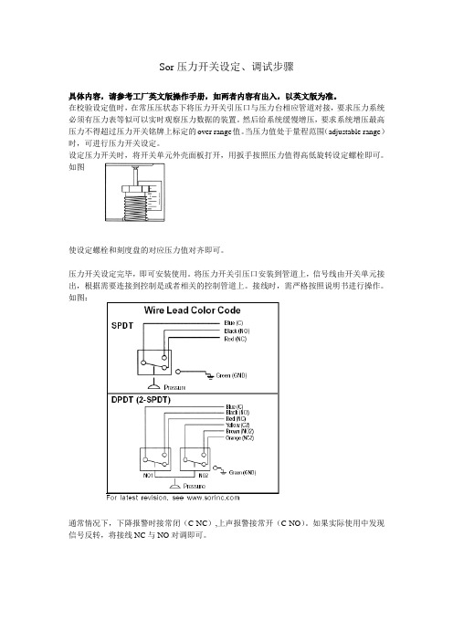
Sor压力开关设定、调试步骤
具体内容,请参考工厂英文版操作手册,如两者内容有出入,以英文版为准。
在校验设定值时,在常压压状态下将压力开关引压口与压力台相应管道对接,要求压力系统必须有压力表等似可以实时观察压力数据的装置。
然后给系统缓慢增压,要求系统增压最高压力不得超过压力开关铭牌上标定的over range值。
当压力值处于量程范围(adjustable range)时,可进行压力开关设定。
设定压力开关时,将开关单元外壳面板打开,用扳手按照压力值得高低旋转设定螺栓即可。
如图
使设定螺栓和刻度盘的对应压力值对齐即可。
压力开关设定完毕,即可安装使用。
将压力开关引压口安装到管道上,信号线由开关单元接出,根据需要连接到控制是或者相关的控制管道上。
接线时,需严格按照说明书进行操作。
如图:
通常情况下,下降报警时接常闭(C-NC),上声报警接常开(C-NO)。
如果实际使用中发现信号反转,将接线NC与NO对调即可。
SOR型号大全及采 购

SOR美国SOR型号大全及采购询价1381851684黄经理SOR公司(中文名称索尔公司)成立于1946年,是世界上唯一一家集生产各类机械及电子压力、差压、温度、流量、液位开关及变送器于一体的专业化国际公司,总部位于美国勘萨斯州州府,现有员工300人,其压力开关类产品产量位居世界第一。
美国SOR开关量仪表SOR防爆开关询~价SOR流量开关SOR询~价SOR差压开关SOR询~价SOR变送器SOR询~价SOR压力开关SORSOR液位开关询~价询~价SOR温度开关SOR询~价1710A-G2A-C-A4-H1-CLSOR询~价9NN-K45-M4-C1A-TTYYWSOR询~价107AL-K40-P1-F0ASOR询~价9NN-K4-N4-F1ASOR询~价9NN-K5-N4-F1ASOR询~价9NN-K45-N4-F1ASOR询~价6NN-K2-N4-F1ASOR询~价6NN-K3-N4-F1ASOR询~价6NN-K5-N4-F1ASOR 6NN-K45-N4-F1A 询~价询~价44V-K2-N4-B1ASOR询~价44V-K4-N4-B1ASOR询~价44V-K5-N4-B1ASOR询~价44V-K45-N4-B1ASOR询~价66V-K2-N4-B1ASOR询~价66V-K3-N4-B1ASOR询~价66V-K5-N4-B1ASOR询~价66V-K45-N4-B1ASOR询~价55V-K3-N4-B1ASOR询~价55V-K5-N4-B1ASOR 55V-K45-N4-B1A 询~价询~价99V-K4-N4-B1ASOR询~价99V-K5-N4-B1ASOR询~价99V-K45-N4-B1ASOR询~价11V-K45-N4-C1ASOR询~价12NN-N66-N4-B1ASOR询~价12NN-N614-N4-B1ASOR询~价12NN-K2-N4-B1ASOR询~价12NN-K4-N4-B1ASOR询~价12NN-K5-N4-B1ASOR询~价12Nn-K45-N4-B1ASOR 4NN-K2-N4-B1A 询~价询~价4NN-K4-N4-B1ASOR询~价4NN-K5-N4-B1ASOR询~价4NN-K45-N4-B1ASOR询~价6NN-K2-N4-F1ASOR询~价6NN-K3-N4-F1ASOR询~价6NN-K5-N4-F1ASOR询~价6NN-K45-N4-F1ASOR询~价5NN-K3-N4-F1ASOR询~价5NN-K5-N4-F1ASOR询~价5NN-K45-N4-F1ASOR 9NN-K5-N4-F1A 询~价询~价9NN-K45-N4-F1ASOR询~价1NN-K45-N4-F1ASOR询~价5RN-EE3-N4-C2A-XSOR询~价757A-F4C-B-A8-N8-SCMRC1C4XSOR询~价733A-F4C-B-A5-N7-WVSCMRC1C4XSOR询~价54RN-KK118-M4-C2A-TTSOR询~价6RN-K5-M9-C2A-TTSOR询~价52L-K116-M9-C2A-TTSOR询~价66V1-K45-N4-B1ASOR询~价6NN-K3-M4-C2ASOR 6NN-K5-M4-C2A 询~价询~价54NN-K118-M4-C2ASOR询~价99VI-K5-N4-C2A-200-1000PSISOR询~价102AD-EG405-P1-C1A-VVYYSOR询~价9BH-JF45-U8-C2ASOR询~价5RN-K3-M4-C2A-TTX373SOR询~价56RN-K316-M4-C2A-TTX373SOR询~价6RN-K3-M4-C2A-TTX373SOR询~价4RN-K45-M4-C2A-TTX373SOR询~价12RN-K5-M4-C2A-TTX373SOR询~价6RN-K5-M4-C2A-TTX373SOR 107EL-EF40-P1-F0A 询~价询~价99V1-K5-N4-C1ASOR询~价12NN-K614-N4-B1ASOR询~价103W1-K805-N4-C1ASOR询~价4NN-EE4-N4-C1A-X373SOR询~价101RN-EE3-M4-C1A-TTX5(X=NOSOR询~价MEANS)SOR询~价5NN-EE5-M9-C2A-TTX4(X=NOSOR询~价MEANS)SOR询~价1NN-T45-N3-C2A-TTSOR询~价101NN-EE3-N4-C1ASOR 4RN-KK45-M2-C1A-CSRRTT 询~价询~价15RB-K5-M2-C1A-CSRRTTSOR询~价1RN-BD45-M4-C1ASOR询~价5RN-BD3-M4-C1ASOR询~价74V1-K118-N4-C1ASOR询~价54RN-KK118-N4-C1ASOR询~价101NN-K45-N4-C1ASOR询~价12NN-K5-N4-C1A-TTX373SOR询~价5AC-AD45-M2-F1ASOR询~价102W1-K912-P1-C2A-TTSOR询~价5NN-K45-W4-F1ASOR 205V1-EE125-U9-C7A-TTX 询~价询~价107AL-K12-P1-F1ASOR询~价101NN-K3-N4-C1ASOR询~价54RN-KK118-N4-C2ASOR询~价54NN-EE118-M4-C2ASOR询~价4NN-EE45-N4-C2ASOR询~价203NN-W105-U9-C7A-C4XSOR询~价54NN-K118-M4-B1ASOR询~价5NN-K3-M4-C2ASOR询~价4NN-K5-M4-C2ASOR询~价103W1-K212-N4-C1ASOR 731A-F7A-B-A2-N4 询~价询~价101NN-KK45-N4-C1A-X1TTSOR询~价12NN-YY4-M4-B1ASOR询~价107EL-EG12-P1-F0ASOR询~价4V3-AG4-N4-B1A-X1TTSOR询~价205NN-T125-U9-C7ASOR询~价301A-F1A-B-A4-N4SOR询~价101LC-EE3-N4-C1A-LLSOR询~价205LC-T125-U9-C7ASOR询~价4BA-KB4-N4-B1ASOR询~价15RB-EE2-N4-C2ASOR 6NN-KK5-N4-F1A 询~价询~价54NN-K118-N4-B1ASOR询~价107AL-N40-P1-F1A-x800SOR询~价107AL-N12-P1-F0A-TTSOR询~价201NN-K115-U9-C7A-TTSOR询~价107AL-N40-P1-F1ASOR询~价107EL-EG12P1-F1A-TT0SOR询~价56RN-EE216-M4-C2ASOR询~价55V1-K3-N4-B1ASOR询~价44V1-K4-N4-B1ASOR询~价99V1-K4-N4-B1ASOR 12NN-K2-N4-C1A 询~价询~价6NN-K5-N4-C1ASOR询~价4NN-EE4-N4-C2ASOR询~价52NN-K116-M4-C1ASOR询~价13RB-K5-N4-F1ASOR询~价203NN-K105-U9-C7ASOR询~价107AL-K12-P1-FOASOR询~价1LC-K45-M4-C2A-RRSOR询~价101NN-K3-N4-F1ASOR询~价66V1-K3-N4-B1ASOR询~价6NN-T5-N4-C1ASOR 103W1-EE212-N4-C2A 询~价询~价15RB-K2-N4-C2A-TTPKSOR询~价4NN-K2-M4-C2A-YY5SOR询~价4NN-K118-M4-C2A-YYSOR询~价6NN-K5-U9-C1ASOR询~价9NN-K5-M4-C1ASOR询~价107AL-N12-P1-F1ASOR询~价12NN-K4-N4-C1ASOR询~价6NN-K5-M4-C1ASOR询~价4NN-KK2-N4-C1ASOR询~价5NN-KK45-N4-C1ASOR 6VV1-K45-N4-C1A 询~价询~价4NN-K2-M4-C1ASOR询~价9L-K4-N4-F1ASOR询~价9L-K5-N4-F1ASOR询~价9L-K45-N4-F1ASOR询~价6L-K2-N4-F1ASOR询~价6L-K3-N4-F1ASOR询~价6L-K5-N4-F1ASOR询~价6L-K45-N4-F1ASOR询~价44V2-EF2-N4-B1ASOR询~价44V2-EF4-N4-B1ASOR 44V2-EF5-N4-B1A 询~价询~价44V2-EF45-N4-B1ASOR询~价66V2-EF2-N4-B1ASOR询~价66V2-EF3-N4-B1ASOR询~价66V2-EF5-N4-B1ASOR询~价66V2-EF45-N4-B1ASOR询~价55V2-EF3-N4-B1ASOR询~价6L-K5-N4-F1ASOR询~价5RN-EE3-N4-C2A-XSOR询~价757A-F4C-B-A8-N8-SCMRC1C4XSOR询~价733A-F4C-B-A5-N7-WVSCMRC1C4XSOR 54RN-KK118-M4-C2A-TT 询~价询~价1NN-K45-M4-C1ASOR询~价6RN-K5-M9-C2A-TTSOR询~价52L-K116-M9-C2A-TTSOR询~价66V1-K45-N4-B1ASOR询~价6NN-K3-M4-C2ASOR询~价6NN-K5-M4-C2ASOR询~价54NN-K118-M4-C2ASOR询~价99VI-K5-N4-C2A-200-1000PSISOR询~价102AD-EG405-P1-C1A-VVYYSOR询~价9BH-JF45-U8-C2A-TTX3SOR 5RN-K3-M4-C2A-TT 询~价询~价56RN-K316-M4-C2A-TTSOR询~价6RN-K3-M4-C2A-TTSOR询~价4RN-K45-M4-C2A-TTSOR询~价12RN-K5-M4-C2A-TTSOR询~价6RN-K5-M4-C2A-TTSOR询~价107EL-EF40-P1-F0ASOR询~价99V1-K5-N4-C1ASOR询~价103W1-K805-N4-C1ASOR询~价4NN-EE4-N4-C1ASOR询~价101NN-EE3-N4-C1ASOR 101RN-EE3-M4-C1A-TTX5(X=NOMEANS) 询~价询~价5NN-EE5-M9-C2A-TTX4(X=NOMEANS)SOR询~价1NN-T45-N3-C2A-TTSOR询~价4LC-EE4-N4-C1A-LLSOR询~价4RN-KK45-M2-C1A-CSRRTTSOR询~价15RB-K5-M2-C1A-CSRRTTSOR询~价1RN-BD45-M4-C1ASOR询~价5RN-BD3-M4-C1ASOR询~价74V1-K118-N4-C1ASOR询~价54RN-KK118-N4-C1ASOR询~价17RB-EE2-N4-C1A-TTSOR 101NN-K45-N4-C1A 询~价询~价12NN-K5-N4-C1A-TTSOR询~价5AC-AD45-M2-F1ASOR询~价102W1-K912-P1-C2A-TTSOR询~价5NN-K45-W4-F1ASOR询~价205V1-EE125-U9-C7A-TTXSOR询~价107AL-K12-P1-F1ASOR询~价101NN-K3-N4-C1ASOR询~价54RN-KK118-N4-C2ASOR询~价54NN-EE118-M4-C2ASOR询~价4NN-EE45-N4-C2ASOR 203NN-W105-U9-C7A-C4X 询~价询~价54NN-K118-M4-B1ASOR询~价5NN-K3-M4-C2ASOR询~价4NN-K5-M4-C2ASOR询~价103W1-K212-N4-C1ASOR询~价731A-F7A-B-A2-N4SOR询~价101NN-KK45-N4-C1A-X1TTSOR询~价12NN-YY4-M4-B1ASOR询~价107EL-EG12-P1-F0ASOR询~价4V3-AG4-N4-B1A-X1TTSOR询~价205NN-T125-U9-C7ASOR 301A-F1A-B-A4-N4 询~价询~价101LC-EE3-N4-C1A-LLSOR询~价4LC-EE4-N4-C1A-LLSOR询~价205LC-T125-U9-C7ASOR询~价4BA-KB4-N4-B1ASOR询~价15RB-EE2-N4-C2ASOR询~价6NN-KK5-N4-F1ASOR询~价54NN-K118-N4-B1ASOR询~价107AL-N40-P1-F1A-x800SOR询~价14RB-KK5-M4-C2ASOR询~价651-K6SOR 5NN-L3-S1-F1A 询~价询~价2NN-L3-S1-D1ASOR询~价203A-A1B-B-B4-N4-TTETXSOR询~价201NN-K115-U9-C7A-TTSOR询~价107AL-N40-P1-F1ASOR询~价12NN-K2-N4-C1ASOR询~价4NN-EE4-N4-C2ASOR询~价107AL-K12-P1-FOASOR询~价1LC-K45-M4-C2A-RRSOR询~价4NN-K2-M4-C2A-YY5SOR询~价6NN-K5-U9-C1ASOR 12RN-KK5-N4-C1A 询~价询~价101RN-EE3-N4-C1ASOR询~价103W1-EE502-N4-C1ASOR询~价15RB-EE2-N4-C1ASOR询~价54NN-KK118-N4-C2A-XITTYYSOR询~价54RN-KK118-M4-C2A-TTYYRKX3X866SOR询~价52RN-KK116-M1-C2A-TTVVYYSOR询~价17S-K2-N4-C2A-TTPKSOR询~价107AL-N12-P1-F0ASOR询~价99V1-K45-S1-C1ASOR询~价44V1-K4-N4-C1ASOR 13RB-K5-N4-F1A 询~价询~价103W1-EE212-N4-C2ASOR询~价9NN-K5-M4-C1ASOR询~价12NN-K4-N4-C1ASOR询~价4NN-K4-N4-C1ASOR询~价102W1-K603-P1-C1A-TTSOR询~价5NN-KK45-N4-F1ASOR询~价201NN-EE125-U9-C7ASOR询~价303A-F1A-B-A4-N4SOR询~价201V1-EE125-U9-C7ASOR询~价107AL-N12-P1-F0A-TTSOR 107EL-EG12-P1-F1A-TT 询~价询~价56RN-EE216-M4-C2ASOR询~价55V1-K3-N4-B1ASOR询~价44V1-K4-N4-B1ASOR询~价101RM-EE3-M4-C1ASOR询~价4RM-EE45-M4-C2ASOR询~价361214-SYW145SOR询~价203NN-K105-U9-C7ASOR询~价54NN-KK118-N4-C1ASOR询~价1NN-K45-M4-C1ASOR询~价5NN-K45-M4-C1A-TTSOR 201NN-KK135-U9-C7A-X 询~价询~价52NN-K116-M4-C2A-TTSOR询~价201NN-K135-U9-C7A-XSOR询~价201NN-K125-U9-C7A-XSOR询~价201NN-K115-U9-C7A-XSOR询~价203NN-K105-U9-C7A-XSOR询~价101NN-EE3-N4-C1ASOR询~价9NN-KK45-U9-C2A-TTYYPKXSOR询~价9NN-K45-M4-C2A-TTYYSOR询~价11V1-K45-N4-C1ASOR询~价12NN-EE4-M4-C1ASOR 4LC-EE4-M4-C1A 询~价询~价5NN-EE45-M4-C1ASOR询~价6NN-EE3-M4-C1ASOR询~价107AL-N40-P1-F1ASOR询~价107AL-N40-P1-F1A-X2SOR询~价4L-K5-M4-C2A-CGSOR询~价52NN-EE116-N4-B1ASOR询~价54NN-K118-M4-C2A-YYSOR询~价99V1-K4-N4-B1ASOR询~价6NN-K5-N4-C1ASOR询~价52NN-K116-M4-C1ASOR 66V1-K3-N4-B1A 询~价询~价6NN-T5-N4-C1ASOR询~价15RB-K2-N4-C2A-TTPKSOR询~价107AL-N12-P1-F1ASOR询~价5NN-KK45-N4-C1ASOR询~价66V1-K45-N4-C1ASOR询~价17RB-EE3-M4-D1ASOR询~价4NN-K2-M4-C1ASOR询~价107EL-EG12P1-F1A-TTSOR询~价1NN-EE45-N4-F1ASOR询~价6NN-K5-M4-C1ASOR 4NN-K5-M4-C1A-RR 询~价询~价1NN-EE45-N4-F1ASOR询~价9NN-K5-N4-C1A-X373SOR询~价6LC-K5-N4-C2A-371SOR询~价20-180PSISOR询~价4NN-K5-M4-C1A-YYSOR询~价9AG-EF45-N1-F1ASOR询~价203RN-EE125-U9-C7ASOR询~价107AL-N12-P1-F0A-X2SOR询~价201V1-K125-U9-C7ASOR询~价4RN-EE45-M1-C1A-PPSOR 107AL-K12-P1-F0A-X 询~价询~价6NN-K3-N4-C2ASOR询~价54L-K118-M4-C2ASOR询~价208A-E1B-F-Z1-N4-ETX2SOR询~价1510B-G5A-C-W9-ES-XSOR询~价12NN-KK4-N4-B1ASOR询~价6L-K3-N4-C2ASOR询~价5NN-K3-N4-C2ASOR询~价303A-F1A-B-A1-N4SOR询~价414864-510382SOR询~价387162-510835SOR 318642-510337 询~价询~价534CR-TN51-P9-Z1A-VTRRSOR询~价101NN-T3-N4-C1ASOR询~价4NN-K4-M4-C2ASOR询~价54RN-EE118-N4-C1ASOR询~价1NN-EE45-N4-C2ASOR询~价6NN-KK5-N4-D1ASOR询~价12NN-K2-M4-B1ASOR询~价12NN-K614-N4-C1ASOR询~价4NN-K4-N4-C2ASOR询~价54NN-K117-N4-C2ASOR 5NN-K5-N4-C2A 询~价询~价651-K8SOR询~价6NN-K5-N4-C2ASOR询~价12L-KK5-M4-C2A-HBSOR询~价17RB-113-M4-D1ASOR询~价6L-KK3-M4-C2A-HBSOR询~价9NN-K45-N1-F1ASOR询~价6RN-EE5-N4-C1ASOR询~价103W1-K502-N4-C1A-TTSOR询~价4NN-EE5-N4-C1ASOR询~价101NN-EE3-N4-C1ASOR 6NN-K3-M4-C2A-TT 询~价询~价44V1-K4-N4-B1ASOR询~价54NN-KK118-N4-C1ASOR询~价4NN-KK4-N4-C1A-XX616SOR询~价9NN-KK45-N1-C1A-XX618SOR询~价5NN-K5-N4-F1ASOR询~价52NN-K116-M4-B1ASOR询~价6NN-K3-N4-F1ASOR询~价12NN-K5-N4-B1ASOR询~价12L-K45-M4-C2A-TTPKSOR询~价5L-K45-M4-C2A-TTPKSOR 4L-K45-M4-C2A-TTPK 询~价询~价9NN-K5-M1-C1A-TTSOR询~价12NN-K614-N4-B1ASOR询~价12NN-K2-N4-B1ASOR询~价BH-009024-009SOR询~价52NN-K116-M4-C2A-TTSOR询~价12NN-K45-N4-B1A-TTSOR询~价101RN-K3-N4-C1A-RRSOR询~价103W1-EE502-N1-C1ASOR询~价101NN-T3-N4-C1ASOR询~价107AL-N40-P1-F1ASOR 201V1-K125-U9-C7A 询~价询~价99V1-K5-N4-C2ASOR询~价403212-SZB712SOR询~价10PSISOR询~价107AL-K40-PI-F0ASOR询~价9NN-K4-M2-C1A-XSOR询~价208A-E1B-F-Y4-N4-CPC4MRC7XSOR询~价BH-003001-003SOR询~价733A-F3D-B-A2-S3SOR询~价720mmSOR询~价431557-0AL100SOR 0-200PSI 询~价询~价SORSOR询~价418252-29LYQISOR询~价638183-SEMDQ1SOR询~价431168-SACZSOR询~价SORSOR询~价201V1-EE125-U9-C7ASOR询~价SORSOR询~价107AL-N12-P1-F1A-TTX3X371SOR询~价SORSOR询~价5NN-K45-W4-F1ASOR SOR 询~价询~价5B3-K5-M4-C1ASOR询~价SORSOR询~价6AG-EG3-M2-C2ASOR询~价34.5-413.7KPaSOR询~价SORSOR询~价403213-QDD005SOR询~价SORSOR询~价15RB-EE2-N4-CIA-X371SOR询~价12NN-N66-N4-B1ASOR询~价12NN-K614-N4-B1ASOR 12NN-K2-N4-B1A 询~价询~价12NN-K4-N4-B1ASOR询~价12NN-K5-N4-B1ASOR询~价12NN-K45-N4-B1ASOR询~价12L-N66-N4-B1ASOR询~价12L-K614-N4-B1ASOR询~价12L-K2-N4-B1ASOR询~价12L-K5-N4-B1ASOR询~价12L-K45-N4-B1ASOR询~价4NN-K2-N4-B1ASOR询~价4NN-K4N4-B1ASOR 4NN-K5-N4-B1A 询~价询~价4NN-K45-N4-B1ASOR询~价12LC-K614-M4-C1A,TTA373SOR。
美国SOR产品系列表
316SS 材质探头
UL: Class I, Group C, Div. 1 UL/CSA: Class I, Group B, Div. 1; ATEX:
接线简易,高可 响应时间0.5~ 靠性 10秒 探头寿命持久
英寸
广泛使用在电厂 和OEM厂家
�
CSA, CE 10amps@250VAC
UL/CSA: Class I, Group B, Div. 1; ATEX: Eex d IIC T6
UL/CSA: Class I, Group A, Div. 1; SnapSw: UL/CSA, ATEX, SAA
备注
NEMA 4, 4X, IP65
15amps@250VAC
CSA, CE
UL: Class I, Group C, Div. 1
UL/CSA: Class I, Group B, Div. 1; ATEX: Eex d IIC T6 UL/CSA: Class I,
Group A, Div. 1; ATEX: Eex d IIC; SnapSw: UL/CSA,
UL: Class I, Group C, Div. 1
CSA, CE ATEX: EEx d IIC; SnapSw: UL/CSA, ATEX, 只适用于干净 的,干燥的气
典型应用为炉膛压 力监测,适用于系 统静压比较恒定的 工况 FM, CSA
不锈钢外壳
不锈钢外壳
的,干燥的气 体,回差小
典型应用为炉膛压力 监测,适用于系统静 压比较恒定的工况 UL/CSA, ATEX, SAA
最高工作压力从 0.25 到 40 适用于微差压0- 系统最大静压为
inwc 107EL
1000mmwc
SOR差压开关101~121使用说明书

1、设定点调整端螺纹(未示)
2、高压端过程连接
3、低压端过程连接
4、严密密封的开关元件封壳
5、18AWG引线(未示)
6、1/2“NPT(M)电气连接
7、3/4”NPT(F)电气连接
8、全天候开关外壳
确保连线与所有的当地和国际的电气方面的规定一致,根据相关的国际和当地的安全规定来安装。
如果达到临界下降差压值,触点关闭,顺时针旋转设定点调整端直到触点改变。重复步骤2-5。
防爆型-AD外壳
JIS/RIIS认证的IIC-T6–JS外壳
CENELEC(BASEEFA)认证的EEx d IIC T6-CL附件
1、凸边帽遮住设定点调整端
2、高压端过程连接1/4”NPT(F)[1/2”NPT(F)]
参考SOR样本459的尺寸,确切的尺寸图,请联系SOR工厂。
标定
普通标定:旋转设定点调整端从而直线移动弹簧引导盘达到标定比例尺上所示的需要的设定点
电气连接
确保连线与所有的当地和国际的电气方面的规定一致,根据相关的国际和当地的安全规定来安装。
警告:在打开防爆型开关的上盖之前,必须断开电源。否则,会导致严重的人员伤害或财产的损坏。
进行电气连接时,要避免电器开关元件的移动。
电气连接不是螺纹接线端部分外壳内部的绝缘板确定。参考图1所示的不同颜色电线的连线图。
精密标定步骤
精密标定步骤依靠稳定的系统压力。在模拟的压力应用场合进行差压开关的标定可以加强设定点精度。建议使用下面的测试仪器。
1、差压计
2、可变压力源
3、排放和均衡阀
4、测试灯或欧姆表
确定在升高或降低设定点时是否有临界设定点的出现,使用相应的程序进行调校。