数据记录仪LR8400(CH)
日置数据记录仪LR8400系列

示波 器在 与 另外 五款 示 波器 产 品 的竞 争 中脱 颖 而
出 ,从而 荣 获这 一奖 项 。“ et nT s”奖授 予 为 B s i et 测试 行 业带 来 重 大技 术 进步 的杰 出产 品。在 过 去 1 2年 中 ,泰克在 该 奖项 的评 比上 每次 均能入 围最 终候 选 名单 ,体 现 了 泰 克公 司 始 终致 力 于工 程 设 计行业 的技 术 创新 。 MS 0 0 O70 0混合信 号 示 波器 拥有 l 6条逻 辑 通
可 以用来在 振动较大 的车 内进行 测量 。另外 ,在对 生产设 备进 行维护 的时候 ,也需要 涉及到几十个 通
道的测量 。
6 完善 了记录媒介 的种类 . 可使 用 U B、C S F卡 等外 部 存储 ,可 以将记 录 到 的数据保 存下来 。另外 ,在记录 中能够实现媒 体 更 换 ,测 量进 行 中将 P C卡等 存储 媒体拔 出,所 测 数 据能够保 存并 且还原 。更值得 一提 的是 ,作为 新 功能通过 U B L N 的链接方式 能与 P S —A C通信 。
计 领域 的重 要作 用 。 ”泰 克公 司高性 能 示波器 总经
理 B i e h说 ,“ r nR i a c 我们的对 手包 括许多著 名的产
品 ,因此荣 获这一 大奖对我们意义重大 。 ”
日置数据记录仪L 4 0 R80 系列
H OK I 1日置 将 在近 期发 售 数据 记 录仪 L 8 0 R 40 3 0通道 ,更可增 加 2 ( 个 最多 6 O通道 )带 1 通道 5
形 分 析 功能 使 力科 公 司 赢 得 了 这 个 重 要 的 合 同。 架构 ,允许 预览和退 出能力 ,以便 用户能毫无延迟
ITAG
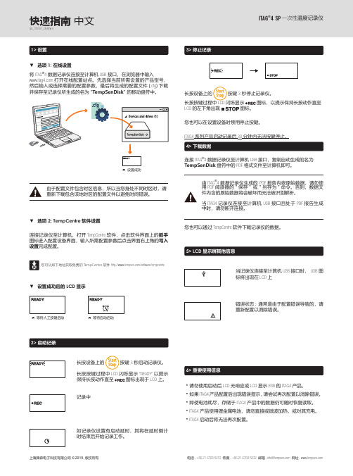
将ITAG ®4数据记录仪连接至计算机USB 接口,在浏览器中输入 打开在线配置站点。
先选择当前所需设置的产品型号,然后输入或选择需要的配置参数,最后将生成的配置文件(.cfg )下载并保存至记录仪所生成的名为"TempSenDisk " 的移动盘符中。
长按设备上的 按键3 秒启动记录仪。
长按按键过程中LCD 闪烁显示"READY"以提示保持长按动作直至 图标出现于LCD 上。
连接记录仪至计算机,打开TempCentre 软件,点击软件界面上的扳手图标进入配置设备界面,输入所需配置参数后点击界面右上角的写入设置完成配置。
ITAG ®4SP 一次性温度记录仪2> 启动记录连接ITAG ®4 数据记录仪至计算机USB 接口,复制自动生成的名为TempSenDisk 盘符中的PDF 格式文件至计算机即可。
由于配置文件包含时区信息,所以当您身处不同时区时,请重新下载包含该地时区的配置文件以避免时间错误。
À等待人工按键启动À等待自动启动由ITAG ®4数据记录仪生成的 PDF 报告内嵌原始数据,请勿使用PDF 阅读器的"保存" 或 "另存为"命令。
否则,数据文件内含的原始数据将会破坏而无法被识别解析。
当ITAG4记录仪连接至计算机 USB 接口且处于PDF 报告生成中时,请勿断开连接。
快速指南 中文QG_190307_CN REV. A您也可以通过TempCentre 软件下载记录仪的数据。
您可从如下地址获取免费的T empCentre 软件 /software/tempcentre长按设备上的 按键3 秒停止记录仪。
长按按键过程中LCD 闪烁显示图标,以提示保持长按动作直至LCD 的左下角出现图标。
您也可以在设置设备时禁用停止按键。
ITAG4系列产品启动记录后30分钟内无法按键停止。
HiLOGGER数据记录器LR8400-20系列产品介绍说明书
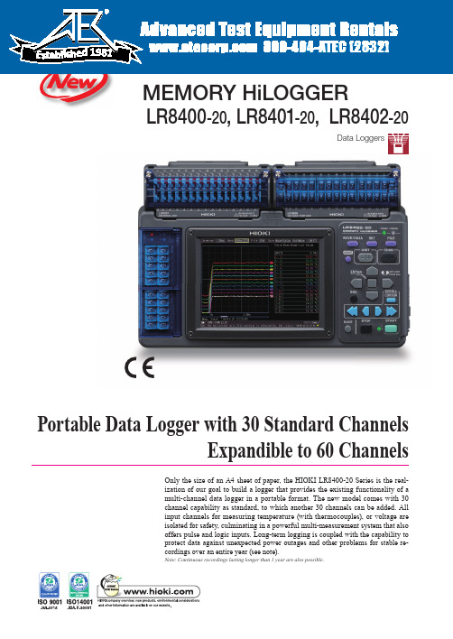
Data Loggers-20-20-20Portable Data Logger with 30 Standard ChannelsExpandible to 60 ChannelsOnly the size of an A4 sheet of paper, the HIOKI LR8400-20 Series is the real-ization of our goal to build a logger that provides the existing functionality of a multi-channel data logger in a portable format. The new model comes with 30 channel capability as standard, to which another 30 channels can be added. All input channels for measuring temperature (with thermocouples), or voltage are isolated for safety, culminating in a powerful multi-measurement system that also offers pulse and logic inputs. Long-term logging is coupled with the capability to protect data against unexpected power outages and other problems for stable re-cordings over an entire year (see note).Note: Continuous recordings lasting longer than 1 year are also possible.2In fuel cell, electric automobile and other development ■ High withstand voltage■ High-speed sampling■ Multi-channel measurementsIn the development of fuel cells, multiple power-generating cells ■ Environmental measurements to prevent global warming ■ Development of fuel cell materials, energy field■ Development of automobiles, testing of automobile parts ■ Maintenance and inspection of equipment■ Monitoring plants■ Testing of electrical products ■ Impedance testing of electronic parts■ Maximum rated voltage to earth: 300 V AC/DC■ Maximum voltage that can be input between terminals: ±100 V DC■ Maximum rated voltage between each channels of VOLTAGE/TEMP UNIT: 250 V DC■ Maximum rated voltage between each channels of UNIVERSAL UNIT: 300 V DC Providesassistance with3Measure and record:■ Temperature & humidity■ A variety of transducer outputs (DC voltage) ■ Resistance valuesAlso comes with high withstand voltage; isolated inputs required when measuring and recording battery cell voltages• Temperature measurements of thermocouples on 30 channels• M3 screw terminal inputs enable secure connection of even thin thermocouples• Special sensor permits humidity measurements on 30 channels (optional Z2000)Note: The sensor power supply is the M3 mm dia. screw terminal block on the left side.Note: Both universal input terminals and M3 mm dia. input terminals enable humidity measurements.• 30 input channelsNote: The LR8400-20, LR8401-20 and LR8402-20 models differ in the combination of input functions and terminals.• All input channels are isolatedNote: Maximum rated voltage above ground between the HiLOGGER and analog inputs is 300 V AC/DC.Note: Maximum channel-to-channel voltage is a high voltage of 300 V DC. (Maximum voltage formodels with M3 screw input terminals is 250 V DC.)• 8 channel inputs (pulse and digital input selectable for each channel)• For measuring energy consumption and cumulative flow• The input signal shares commonground with the HiLOGGERNote: M3 screw input terminals provide direct connection• 8 channel inputs (pulse and digital input selectable for each channel)• For measuring rotational irregularities of motors and drills• The input signal shares commonground with the HiLOGGERNote: M3 screw input terminals provide simple connection• 8 channel inputs (digital and pulse input selectable for each channel)• 1 or 0 is recorded for each recording interval• The input signal shares commonground with the HiLOGGERNote: M3 screw input terminals provide simple connectionLogical 1-0 measurementPulse rotations measurementHighlightsMulti-measurements• Universal inputs support temperature measurements using Platinum resistance temperature sensor (Pt100/ JPt100), or resistance measurements (four wires)Note: These cannot be measured using the M3 screw input terminals units.Note: Supports resistance recording to enable assessment ofchanges in resistance in the device under test. 4-terminal method, measurement resolution 0.5 mΩ -, testing current 1 mA■ A compact A4 size enhances mobilityA compact A4 size footprint makes it ideal for use in virtually any environment.■ Helps also in collecting automotive data Ideal for testing and collecting data on the vibration characteristics of automotive partsive dataotive da the on the To record 4 - 20mA instrumentation signals, attach a commercially available 250Ω shunt resistanceto the input terminals (between + and -) to convert the signals to 1 - 5 V. Then use the 1-5V or the 10V f.s. input range in the HiLOGGER.4■ Enhanced noise suppressionA digital oversampling fi lter function reduces inverter switching noise and 50/60 Hz hum noise, a concern in earlier models, during recording.Note: The noise reduction effect improves with longerrecording intervals (i.e., at slower sampling speeds).Sampling at 100 ms intervals cannot capture abrupt load changes■ 10 ms high-speed samplingThe development of hybrid and electric automobiles requires instruments that can measure abrupt load changes. Channels 1 to 15 provide 10-ms sampling and channels 16 to 30 provide 20-ms sampling. This channels allow you to track waveforms not possible with earlier models.Note: Measurements on channels 31 to 60 provide 50-ms sampling.Accurately capture any phenomena you want to measureSampling the same waveform at ten times the speed, at 10 ms intervals,accurately captures the changes.Without electric noise reduction, you will obtain a waveform like the one above in temperature measurements of an electromagnetic cookerA digital fi lter in the HiLOGGER eliminates high-frequency noise to enable accuratetemperature waveforms■ 5.7 inch TFT LCD display is easy to view even at an angleThe LCD has a wider visual angle and is larger (5.7 inches, 640 × 480 dots)than the STN LCD in our previous model (8420-51s) to facilitate observation of waveforms on multiplechannels.HighlightsHigh-speedRecordingHighlightsNoisesuppressionHighlightsEasy-to-view LCD5■ Compatible with USB memory devicesFor even greater convenience, the HiLOGGER now provides support for USB memory devices. Measurements can now immediately be written to a USB memory device in real-time. USB memory devices are also a handy means to transfer data to a PC.Note: Although USB memory devices enable real-time saving of data, for more reliable data protection we recommend use of HIOKI CF cards, which are guaranteed to work with the instrument, for real-time saving of data.■ Cards can be replaced during real-time recordingThis function has been provided to enable removal of cards during recording to allow the user to analyze the data recorded so far.This makes it possible to replace USB memory devices and CF cards during real-time recording without having to stop measurements.Note: During high-speed recording, be sure to insert the new storage media within 2 minutes ofremoving a card.Recording intervalsRecording of 15 analog channels only (no pulse measurement, alarm output or waveform processing data)Internal memory (16 MB)Model 9727(256 MB)Model 9728(512 MB)Model 9729(1 GB)Model 9830(2 GB)10 ms ** For 15 or fewer analog channels1h 33m 1d 00h 51m2d 01h 42m4d 03h 25m8d 06h 50mRecording intervalsRecording of 30 analog channels only (no pulse measurement, alarm output or waveform processing data)Internal memory (16 MB)Model 9727(256 MB)Model 9728(512 MB)Model 9729(1 GB)Model 9830(2 GB)20 ms ** For 30 or fewer analog channels1h 33m 1d 00h 51m 2d 01h 42m 4d 03h 25m 8d 06h 50m 50ms 3h 53m 2d 14h 08m 5d 04h 16m 10d 08h 33m 20d 17h 06m 100ms 7h 46m 5d 04h 16m 10d 08h 33m 20d 17h 06m 41d 10h 12m 200ms 15h 32m 10d 08h 33m 20d 17h 06m41d 10h 12m82d 20h 24m500ms 1d 14h 50m 25d 21h 22m51d 18h 45m 103d 13h 30m 207d 03h 01m1s 3d 05h 40m51d 18h 45m 103d 13h 30m 207d 03h 01m 414d 06h 03m2s 6d 11h 20m 103d 13h 30m 207d 03h 01m 414d 06h 03m "★"5s 16d 04h 21m 258d 21h 47m 517d 19h 34m "★""★"10s 32d 08h 43m 517d 19h 34m"★""★""★"20s 64d 17h 26m "★""★""★""★"30s 97d 02h 10m "★""★""★""★"1min 194d 04h 20m "★""★""★""★"2min388d 08h 40m"★""★""★""★"5min to 1hour"★""★""★""★""★"• Maximum recording time is inversely proportional to number of recording channels.• Because the actual capacity of a CF card is less than that indicated, and because the header portion of waveform files is not included in capacity calculations, expect actual maximum times to be about 90% of those in the table.• "★" exceeds 1 year.Note: Use only HIOKI CF cards that are guaranteed to operate with the HiLOGGER for continuous long-term recording.Store data securely for more than 1 year■ Saving data to CompactFlash (CF) cardUse only HIOKI CF cards, which are manufactured to strict industrial standards, for long-term storage of important data.Note: Operation of non-HIOKI CF cards is not guaranteed■ Recording CapacityHighlightsStorage MediaHighlightsReplacing cards6■ Up to two additional 15 channel input units can be addedThe need for more measurement channels can be met even after purchasing the instrument. Theinstrument comes with 30 channels as standard, but another two 15 channel input units can be added to expand the total number of channels to 60.Note: The units provided with the unit as standard cannot be removed.A host of useful functions and features■ Input setting screens with waveform monitoringThe HiLOGGER adopts the setting screens that earned its sister model (8430-20) a reputation for user-friendliness. Range settings, warnings, triggers, waveform processing and other measurement input settings can be taken in at aglance.VOLTAGE/TEMP UNIT LR8500● 15ch● M3 screw terminals(2 terminals per channel)UNIVERSAL UNIT LR8501● 15ch● Push-button type terminals(4 terminals per channel)Function highlightsEasyinstallationFunction highlightsEase of use7LAN■ USB and LAN connection for easy setupThe supplied Logger Utility software allows you to set up the logger from a PC. Setup could not be easier. Just follow the numbered procedures to set up the instrument.Note: Data on an inserted CF card can be copied to a PC via USBconnection.Note: The Logger Utility will enable LAN access with software Ver. 1.20or later.■ Simultaneous recording to storage media and PCMeasurement data can be simultaneously saved to external storage media and a hard disk on a PC connected to a network to reduce the risk data loss.USB■ Real-time processing functionsThe HiLOGGER comes with [four arithmetic operation] functions for processing between channels. Data processed in real-time can be displayed in graph form. In addition, processing results for 30 channels are stored in internal memory and can be handled as data for independent input channels.Trickle charging the internal batteryAn internal battery (optional accessory) is charged when the AC adapter is connected. Since the internal battery will automatically take over in the event of a sudden power outage, it permits uninterruptible operation.■ Protection of files being stored on external storage mediaAn internal high-capacity capacitor will provide enough power to store any data at risk on a CF card or USBmemory device should a sudden power outage occur during long-term storage. This reduces the risk of data loss and corruption of the fi le system. Measurements will resume as soon as the power returns.■ Alarm outputThe HiLOGGER outputs a signal when alarm criteria are satisfi ed and also sounds a buzzer. Four systems are provided as standard and separate criteria can be set for each input source enabling OR and AND criteria between channels.Note: Open-collector output (5 V voltage output and relay drive capacity 5 to 30 V, 200 mA)■ Records average values every 30 minutesThe HiLOGGER contains a [time-span processing]function. The instrument will save processing data as text data for a preset time period in real-time.Function highlightsAlarm output■ An is cconwilof aFunction highlightsWeathers power outagesFunction highlightsCalculation FunctionsFunction highlightsUSB / LAN Communication8■ Analyze after measuringOur new “dual-knob function” greatly simplifi es data analysis. Two separate waveform windows are provided, with the displayed waveforms showing different time-axis scales (time bases). This capability substantially simplifi eslong-term data analysis. (Patent pending)Segment A50 ms/div magnification Segment B100 ms/div magnificationEntire Recording Length: 1 s/divSegment A ViewSegment B ViewSpans entire recording length■ The supplied Logger Utility software enables processing of measurement data on View past data during recording Output PC data to a printera PC■View past data during re ■ Output PC data to a print ■ Control of measurements from a PC screenConnect the PC to the HiLOGGER using USB or via LAN*(see note). Use the supplied Logger Utility software to record data on a PC in real-time. Scroll backwards through the displayed trend graph window to view past waveforms even while recording. Up to fi ve HiLOGGERs can be connected to one PC.Bundled user-friendly software for PC analysis■ Remote control through HTTP server function*Without the need to install additional software, you can use an ordinary web browser on your PC to set up the HiLOGGER, acquire data and monitor data on the screen.■ Data acquisition via FTP*FTP allows the PC to acquire fi les stored on HiLOGGER storage devices or measurement data in internal memory.ed of storage invoked, alarm occurrence and other events via E-mail.*Note: LAN communication functions support planned from software Ver. 1.20.Function highlightsPCMeasurement9■ Product Specifications10■ Product Specifications(product and accuracy guaranteed for one year)(input type selectable from voltage, thermocouple, Pt 100/ JPt 100, humidity,11, at least 512 MB of memory ■ Bundled software specificationsterminals × 15terminals × 15terminals × 15terminals × 15terminals × 15terminals × 15Headquarters :81 Koizumi, Ueda, Nagano, 386-1192, Japan TEL +81-268-28-0562 / FAX +81-268-28-0568 http://www.hioki.co.jp/E-mail:***************.jp HIOKI USA CORPORATION :6 Corporate Drive, Cranbury, NJ 08512 USA TEL +1-609-409-9109 / FAX +1-609-409-9108/E-mail:******************All information correct as of Feb. 10, 2012. All specifi cations are subject to change without notice.LR8400-20E8-22M-00KR Printed in KoreaDISTRIBUTED BYHIOKI (Shanghai) Sales & Trading Co., Ltd. :1608-1610,Shanghai Times Square Offi ce, 93 Huai Hai Zhong Road Shanghai, P.R.China POSTCODE: 200021TEL +86-21-63910090/63910092 FAX +86-21-63910360/E-mail:**************.cn Beijing Offi ce : TEL +86-10-84418761 / 84418762Guangzhou Offi ce : TEL +86-20-38392673 / 38392676HIOKI INDIA PRIVATE LIMITED :Khandela House, 24 Gulmohar Colony Indore 452 018 (M.P.), India TEL +91-731-4223901, 4223902 FAX +91-731-4223903http://www.hioki.in/E-mail:*************HIOKI SINGAPORE PTE. LTD. :33 Ubi Avenue 3, #03-02 Vertex, Singapore 408868TEL +65-6634-7677 FAX +65-6634-7477E-mail:**************.sgNote: Company names and Product names appearing in this catalog are trademarks or registered trademarks of various companies.PC communicationRemovable storage (CF card)Supplied with PC Card adapterPC Card PrecautionUse only PC Cards sold by HIOKI. Compatibility and performance are not guaranteed for PC cards made by other manufacturers. You may be unable to read from or save data to such cards.Power supplies BATTERY PACK Z1000NiMH, Charges while installedCharges while installed in the HiLOGGERCasesCARRYING CASE C1000 Includes compartment for optionsFIXED STAND Z5000For wall hanging and slanted bench mountingMeasurement and input optionsPC CARD 2G 9830(2 GB capacity)PC CARD 1G 9729(1 GB capacity)PC CARD 512M 9728(512 MB capacity)PC CARD 256M 9727(256 MB capacity)LAN CABLE 9642Straight Ethernet cable, supplied with straight to cross conversion adapter, 5 m(16.41 ft) lengthHUMIDITY SENSOR Z20003 m (9.84 ft) lengthVOLTAGE/TEMP UNIT LR85002 terminals M-3 mm screw type, 15 channels Voltage, Temperature with thermocouple, or Humidity measurementUNIVERSAL UNIT LR85014 terminals push-button type, 15 channels Voltage, Temperature with thermocouple, Platinum Resistance temperature sensor, Humidity, or Resistance measurementLR8400-20 (with built-in VOLTAGE/TEMP UNIT × 2)Built-in units are equivalent to the VOLTAGE/TEMP UNIT LR8500 (15 ch) × 2Caution: Built-in units cannot be removed or changedLR8401-20 (with built-in UNIVERSAL UNIT × 2)LR8402-20(with built-in UNIVERSAL UNIT × 1, VOLTAGE/TEMP UNIT × 1)AC ADAPTER 9418-15Supplied as standard, 100 to 240 V ACBuilt-in units are equivalent to the UNIVERSAL UNIT LR8501 (15 ch) × 2Caution: Built-in units cannot be removed or changedBuilt-in units are equivalent to the UNIVERSAL UNIT LR8501 (15 ch) × 1, andVOLTAGE/TEMP UNIT LR8500 (15 ch) × 1Caution: Built-in units cannot be removed or changedMain units and Options in Detail。
Lorex NR810系列产品说明书

Router*HDMI OR* Not included / sold separately.** Cameras are included only with bundled systems. Stand-alone systems do not include cameras.For the best video output this NVR can provide, you must use it with a monitor that supports 4K resolution.!Quick Start GuidesUSB MouseEthernet CableFor PoE switch installations only.Ethernet Extension Cable*NOTE: It may take up to 1 minute for cameras to start up and transmit video to your NVR.Recommended: Connect cameras ORConnect cameras to a PoE switch*or router*your network. Visit Search for the model numberof your productwould like to playback. Click the display options( Using the Quick MenuRight-click to open the Quick Menu.Click and select SettingNR810_SERIES_QCG_EN_R1If the Status indicator is red, click Update the camera user name, password, 4. 5. Click Apply to save changes.Quick Access to System InformationTo quickly open a window that displays vital system information such as device ID, firmware version, and device IP address:1. During live view, right-click anywhere on the screen to open the Quick Menu.2. Click Info . If prompted, enter the system user name (default: admin ) and your new, secure password.321open the Navigation Bar. Move the mouse cursor away from the bottom of the。
安利杰 RD-8100系列数据记录仪说明书

S-19Display Horizontal Resolution:graph 1 dot/recording interval RAM BATTERYType:Lithium (AA size), included Working Voltage:3.5 Vdc Capacity:1800 mAHBattery Life:1 year, 2 channel;replaceable without loss of data MAIN BATTERYType:sealed lead acid, rechargeable, included Working Voltage:Battery Life:12 hr, 2 channels,charged (5.5 hr for 8 channels)MEMORY CARD BATTERY Type:Lithium, included Working Voltage:3.5 Vdc Capacity:165 mAHBattery Life:4 yr (128 K byte card)CONFIGURATION User Password:4 digits (factory set, active or inactive via switch setting)Date:MM/DD/YY Time (Military):Hour:Minute:SecondA/INRD-8100 Series$2595Basic UnitߜUp to 8 Channels of Isolated InputߜDot Matrix LCD Screen DisplayߜAccepts Thermocouples,mV , V , mA Inputs and MoreߜBattery or ac Powered ߜRS-232 Communications PortߜOptional Memory Cards for Data StorageSpecificationsNo. of Inputs:1, 2, 4, 6, or 8Overall Accuracy:0.1% of span Linearity Accuracy:±0.1°C (T/C and RTD inputs)Portable Paperless Recorders Quick Disconnect andTransition Joint Thermocouples sold separately. See Section A formany other thermocouples.KQSS-116G-12, $22,see page A-64.TJ36-CASS-316G-6, $29,see page A-85.D I S C O N T I N UE DThe OMEGA ®RD-8100 Series recorder is an advanced,microprocessor-based recording and display system that provides continuous monitoring on eight isolated input channels of voltage,current or thermocouples. The RD-8100 is paperless, making it perfect for fiber-sensitive clean room applications. The unit may be ac or dc powered and weighs only about ten pounds, making it an ideal portable monitoring station for field,industrial or laboratory applications.A dot matrix screen displays your data in graphic (bar or line) as well as digital formats. Data is displayed and recorded in engineering units which are configured via thefunction keypad. As the screen is filled, data is recorded on 64 K (per channel) of internal memory. Data can be transferred at any time to a removable and reusable memory card or to a computer via RS-232port. The memory card provides permanent storage, or data can be downloaded to a PC.Resolution:12-bitSample Rate:every 125 msec Input Isolation:500 V rms Standard Inputs:4 to 20 mA (5 Ω, 0.1 V drop);0 to 1, 0 to 5, 1 to 5, 0 to 10 Vdc,mV, thermocouple; other inputs available by special order: RTD,strain gage, potentiometer Input Impedance:>15 M ΩOutput Power:+24 Vdc @ 160 mA to power up to 8 external transmittersRAM Memory:32,000 data points per channel (64 K bytes)Recording Time:32,000 x recording interval; 8.9 hr for 1 sec, 111 days for 5 min, 3.6years for 1 hr recording interval Memory Card:512 K bytes Display Type:supertwistdot matrix LCD (100 x 64 dots)Display Area:89 x 57 mm (3.5 x 2.25")Display Vertical Resolution:graph 64 dots (1.56% of span)Optional memory card, RD-8100-MC512,$250. See page S-20S-20†Specify channel number.††Specify “H ” for high alarm or “L ” for low alarm.Ordering Example: RD8102-(J-0-200F)-(4-20MA)-A1H-A1L-A2H-A2L , two-channelrecorder, channel 1 configured for type J thermocouple with 0 to 200°F/-18 to 93°C range,channel 2 configured for a 4 to 20 mA input, high and low alarms on channel 1 and on channel 2, $2595 + 4(50) = $2795RD-8100-MC512optional memory card available, $250.D I S C T I N UE DRecording Interval:0.25 sec to 1 hr (in 0.25 sec steps)Recording Method:Average, Peak, Valley, All No. of Inputs:1 through 8ID Code:6 characters (alphanumeric)Input Type:T/C types J, K, E, T, R, S, C; mV, V,A, mA; RTD on special order Input Display Range:4 digit (-9999 to +9999)Calibration:Apply min and max input signal to recorder for auto-calibration Engineering Unit:3 character max. (GPM, PSI)Alarms:One high, one low, settable anywhere across span Alarm Relays:1 or 2 per channel,SPDT 3 A contacts GENERALOperating Temperature:0 to 50°C (32 to 122°F)Storage Temperature:-20 to 70°C (-4 to 158°F)General Dimensions:160 H x 247 W x 318 mm D (65⁄16x 913⁄16x 121⁄2")Panel Cutout:154 H x 243 mm W (61⁄16x 99⁄16")Housing:steel, textured enamel finish (panel mount special order)Weight:5.86 kg (12.9 lb)Power Requirements:switchable 115 or 220 Vac, 50/60 Hz 8.2 VA,Dual channel; 15 VA, eight channel Communications Port: RS-232Software for PC:Supports both memory card reader and unit directlyCANADA www.omega.ca Laval(Quebec) 1-800-TC-OMEGA UNITED KINGDOM www. Manchester, England0800-488-488GERMANY www.omega.deDeckenpfronn, Germany************FRANCE www.omega.frGuyancourt, France088-466-342BENELUX www.omega.nl Amstelveen, NL 0800-099-33-44UNITED STATES 1-800-TC-OMEGA Stamford, CT.CZECH REPUBLIC www.omegaeng.cz Karviná, Czech Republic596-311-899TemperatureCalibrators, Connectors, General Test and MeasurementInstruments, Glass Bulb Thermometers, Handheld Instruments for Temperature Measurement, Ice Point References,Indicating Labels, Crayons, Cements and Lacquers, Infrared Temperature Measurement Instruments, Recorders Relative Humidity Measurement Instruments, RTD Probes, Elements and Assemblies, Temperature & Process Meters, Timers and Counters, Temperature and Process Controllers and Power Switching Devices, Thermistor Elements, Probes andAssemblies,Thermocouples Thermowells and Head and Well Assemblies, Transmitters, WirePressure, Strain and ForceDisplacement Transducers, Dynamic Measurement Force Sensors, Instrumentation for Pressure and Strain Measurements, Load Cells, Pressure Gauges, PressureReference Section, Pressure Switches, Pressure Transducers, Proximity Transducers, Regulators,Strain Gages, Torque Transducers, ValvespH and ConductivityConductivity Instrumentation, Dissolved OxygenInstrumentation, Environmental Instrumentation, pH Electrodes and Instruments, Water and Soil Analysis InstrumentationHeatersBand Heaters, Cartridge Heaters, Circulation Heaters, Comfort Heaters, Controllers, Meters and SwitchingDevices, Flexible Heaters, General Test and Measurement Instruments, Heater Hook-up Wire, Heating Cable Systems, Immersion Heaters, Process Air and Duct, Heaters, Radiant Heaters, Strip Heaters, Tubular HeatersFlow and LevelAir Velocity Indicators, Doppler Flowmeters, LevelMeasurement, Magnetic Flowmeters, Mass Flowmeters,Pitot Tubes, Pumps, Rotameters, Turbine and Paddle Wheel Flowmeters, Ultrasonic Flowmeters, Valves, Variable Area Flowmeters, Vortex Shedding FlowmetersData AcquisitionAuto-Dialers and Alarm Monitoring Systems, Communication Products and Converters, Data Acquisition and Analysis Software, Data LoggersPlug-in Cards, Signal Conditioners, USB, RS232, RS485 and Parallel Port Data Acquisition Systems, Wireless Transmitters and Receivers。
Omega OM-EL-2-IR 8位可移动数据记录仪说明书
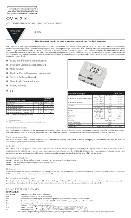
OM-EL-2-IR8BIT PORTABLE DATALOGGER WITH INFRARED COMMUNICATIONSRS232and InfraRed Communications Uses IrDA Communication Standard Multi-functionIdeal For Use In Hazardous Environments No Extra Software Needed Line-of-sight Communication Battery PoweredThe OM-EL-2-IR data logger enables both InfraRed and/or RS232communication between the logger and the PC or OM-EL-HL.OM-EL-2-IR is an easy method of measuring,displaying and recording temperature,humidity,pH,voltage,current,etc.,with a memory for 8064readings and a battery life of up to 3years**.OM-EL-2-IR can operate as a 'stand alone'logger or be permanently connected to a system.The OM-EL-2-IR serial link is addressable and up to 8loggers can be connected to one serial port.The PC software operates under Windows 3.1and does not require specialist skill to operate.Data output is in text format and can be easily integrated into any popular spreadsheet.Graphical output is possible under OM-EL-WIN.Consult the EasyLog software manual for further details.*Sensor dependent.**Battery life dependent on input mode and sampling rate.Communications areaCable communicationsAt the PCFor experienced EasyLog usersOperating InstructionsIR timeoutCommunications can take place at distances from 0m (i.e."nose-to-nose")to 1m.The OM-EL-2-IR and the IR port on the PC should be pointing at each other.The IR beam spans about 30°,so the two devices do not have to be directly aligned,however there should be a clear line-of-sight between the two.The RS232cable will work as normal,regardless of whether the IR circuitry is on or not.However,attempting to use both the cable and the InfraRed simultaneously will result in communication errors.The OM-EL-2-IR is designed to communicate with devices which have IrDA-compatible InfraRed ports.If your computer doesn't have one of these,OMEGA’s OM-EL-LINK-IR can be used to convert a normal serial port.Simply plug the OM-EL-LINK-IR into the 9-way serial port and point it in the right direction.If you use a serial extension cable,ensure that it is a straight-through.Null modem and EasyLog cables will not work.Pressing the button to turn on the IR circuitry will not affect the logger itself,e.g.if it's in push to start,or push to log mode.Conversely,a short press,say for a push to log,will not affect the IR circuitry.The duration that the button is held down for determines what the press is intended for.Step 1:Step 2:Step 3:Simply hold down the button for 2-3seconds.The Actiwave symbol will flash once.Place the logger in line of sight of the IR port on your PC.That's it!T o maximise battery life,after no communications activity has occurred for about five minutes,the IR circuitry will automatically shut down.If the button is held down until the Actiwave flashes,the timeout period will be reset.USING EXTERNAL SIGNALSPIN FUNCTION A1,A2,REF .Output for test diagnostics.Do not use.HA.High Alarm output =V+when alarmed.SW .'Push to record event'input.Active low -operated by front switch,subject to Push-to-Start.RS.Reset input.Active low -operated by RESET switch.NOTE -logging will stop and restart at .Low Alarm output =V+when alarmed.A+.Output =V+when a in progress.V+.Battery positive.V-.Batery negative.DO NOT APPLY AN EXTERNAL SUPPLY ACROSS THESE PINS WITH BATTERY IN PLACE.Only connect outputs to inputs,otherwise performance will be battery life drastically reduced.OMEGAnet On-Line Service Internet e-mail info @Servicing North America:Servicing Europe:USA:Canada:USA and Canada:Mexico and Latin America:Benelux:Czech Republic:France:Germany/Austria:United Kingdom:One Omega Drive,Box 4047Stamford,CT 06907-0047Tel:(203)359-1660FAX:(203)359-7700e-mail:info 976BergarLaval (Quebec)H7L 5A1Tel:(514)856-6928FAX:(514)856-6886e-mail:canada Sales Service:1-800-826-6342/1-800-TC-OMEGACustomer Service:1-800-622-2378/1-800-622-BESTEngineering Service:1-800-872-9436/1-800-USA-WHEN TELEX:996404EASYLINK:62968934CABLE:OMEGA Tel:(95)800-TC-OMEGA FAX:(95)203-359-7807En Español:(203)359-1660ext:2203e-mail:Postbus 8034,1180LA Amstelveen,The Netherlands Tel:(31)206418405FAX:(31)206434643Toll Free in Benelux:060993344e-mail:nl Ostravska 767,73301KarvinaTel:42(69)6311899FAX:42(69)6311114e-mail:czech 9,rue Denis Papin,78190TrappesTel:(33)130-621-400FAX:(33)130-699-120Toll Free in France:0800-4-06342e-mail:france Daimlerstrasse 26,D-75392Deckenpfronn,GermanyTel:49(07056)3017FAX:49(07056)8540Toll Free in Germany:0130112166e-mail:germany 25Swannington Road,PO Box 7,Omega Drive,Broughton Astley,Leicestershire,Irlam,Manchester,LE96TU,England M445EX,England Tel:44(1455)285520Tel:44(161)777-6611FAX:44(1455)283912FAX:44(161)777-6622Toll Free in England:0800-488-488e-mail:uk ISO 9001Certified ISO 9002Certified @@@@@@@@For immediate technical or application assistance:espanol WARRANTY/DISCLAIMERRETURN REQUESTS /INQUIRIESOMEGA ENGINEERING,INC.warrants this unit to be free of defects in materials and workmanship for a period of from date of purchase.OMEGA Warranty adds an additional one (1)month grace period to the normal to cover handling and shipping time.This ensures that OMEGA’s customers receive maximum coverage on each product.If the unit should malfunction,it must be returned to the factory for evaluation.OMEGA’s Customer Service Department will issue an Authorized Return (AR)number immediatelyupon phone or written request.Upon examination by OMEGA,if the unit is found to be defective it will be repaired or replaced at no charge.OMEGA’s WARRANTY does not apply to defects resulting from any action of the purchaser,including but not limited to mishandling,improper interfacing,operation outside of design limits,improper repair,or unauthorized modification.This WARRANTY is VOID if the unit shows evidence of having been tampered with or shows evidence of being damaged as a result of excessive corrosion;or current,heat,moisture or vibration;improper specification;misapplication;misuse or other operating conditions outside of OMEGA’s ponents which wear are not warranted,including but not limited to contact points,fuses,and triacs.CONDITIONS:Equipment sold by OMEGA is not intended to be used,nor shall it be used:(1)as a “Basic Component”under 10CFR 21(NRC),used in or with any nuclear installation or activity;or (2)in medical applications or used on humans.Should any Product(s)be used in or with any nuclear installation or activity,medical application,used on humans,or misused in any way,OMEGA assumes no responsibility as set forth in our basic WARRANTY/DISCLAIMER language,and additionally,purchaser will indemnify OMEGA and hold OMEGA harmless from any liability or damage whatsoever arising out of the use of the Product(s)in such a manner.Direct all warranty and repair requests/inquiries to the OMEGA Customer Service Department.BEFORE RETURNING ANY PRODUCT(S)TO OMEGA,PURCHASER MUST OBTAIN AN AUTHORIZED RETURN (AR)NUMBER FROM OMEGA’S CUSTOMER SERVICE DEPARTMENT (IN ORDER TO AVOID PROCESSING DELAYS).The assigned AR number should then be marked on the outside of the return package and on any correspondence.The purchaser is responsible for shipping charges,freight,insurance and proper packaging to prevent breakage in transit.FOR RETURNS,please have the following FOR REP AIRS,consult OMEGA for information available BEFORE contacting OMEGA:current repair charges.Have the following information 1.P .O.number under which the product was PURCHASED,available BEFORE contacting OMEGA:2.Model and serial number of the product under warranty, 1.P .O.number to cover the COST of repair,and 2.Model and serial number of the product,and 3.Repair instructions and/or specific problems relative to 3.13months one (1)year product warranty OMEGA is pleased to offer suggestions on the use of its various products.However,OMEGA neither assumes responsibility for any omissions or errors nor assumes liability for any damages that result from the use of its products in accordance with information provided by OMEGA,either verbal or written.OMEGA warrants only that the parts manufactured by it will be specified and free of defects.OMEGA MAKES NO OTHER WARRANTIES OR REPRESENTATIONS OF ANY KIND WHATSOEVER,EXPRESSED OR IMPLIED,EXCEPT THAT OF TITLE,AND ALL IMPLIED WARRANTIES INCLUDING ANY WARRANTY OF MERCHANTABILITY AND FITNESS FOR A PARTICULAR PURPOSE ARE HEREBY DISCLAIMED.LIMITATION OF LIABILITY:The remedies of purchaser set forth herein are exclusive and the total liability of OMEGA with respect to this order,whether based on contract,warranty,negligence,indemnification,strict liability or otherwise,shall not exceed the purchase price of the component upon which liability is based.In no event shall OMEGA be liable for consequential,incidental or special damages.WARRANTY NON-WARRANTY Repair instructions and/or specific problems relative to the product.the product.OMEGA’s policy is to make running changes,not model changes,whenever an improvement is possible.This affords our customers the latest in technology and engineering.OMEGA is a registered trademark of OMEGA ENGINEERING,INC.©Copyright 1996OMEGA ENGINEERING,INC.All rights reserved.This document may not be copied,photocopied,reproduced,translated,or reduced to any electronic medium or machine-readable form,in whole or in part,without prior written consent of OMEGA ENGINEERING,INC.It is the policy of OMEGA to comply with all worldwide safety and EMC/EMI regulations that apply.OMEGA is constantly pursuing certification of its products to the European New Approach Directives.OMEGA will add the CE mark to every appropriate device upon certification.The information contained in this document is believed to be correct but OMEGA Engineering,Inc.accepts no liability for any errors it contains,and reserves the right to alter specifications without notice.These products are not designed for use in,and should not be used for,patient connected applications.WARNING:BATTERY REPLACEMENTWARNING:Handle lithium batteries carefully -observe warnings on battery casing.Dispose of in accordance with local regulations.Only use ½AA 3.6V lithium.The list below is not exhaustive.Check with supplier that the battery you are ordering is 'press fit'and is not fitted with solder tags or leads.T ake care to connect correctly.Battery LifeThe IR circuitry draws virtually zero current when it is turned off.Because of this,if it is permanently off,the battery life of the OM-EL-2-IR will be practically the same as a normal OM-EL-2.When the IR circuitry is turned on,current consumption dramatically increases.If it is permanently on,the battery life will be drastically reduced.However,if this is not a problem (e.g.if using an external power supply)making solder Link 1,as shown in the diagram,will cause the IR circuitry to stay on all the time.。
RC-系列温湿度记录仪产品目录
温湿度记录仪
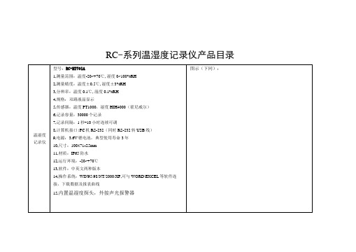
型号:RC-HT701A
1,测量范围:温度-20~+70℃,湿度0~100%RH
2,测量精度:温度±0.5℃,湿度±3%RH
3,分辨率:温度0.1℃,湿度0.1%RH
4,规格:双路液晶显示
5,传感器:温度PT1000,湿度HIH4000(霍尼威尔)
6,记录容量:30000个记录
7,记录间隔:1秒-10小时连续可调
接,下载数据及报表曲线
15,外接温湿度探头,无报警
型号:RC-DT618B
1,测量范围:温度-40〜+100℃
2,测量精度:温度±0.5℃
3,分辨率:温度0.1℃
4,规格:双路液晶显示
双温度记录仪
5,传感器:温度NTC
6,记录容量:30000个记录
7,记录间隔:1秒-10小时连续可调
8,计算机接口:PC机RS-232(同时RS-232转USB线)
型号:RC-T701A
1,测量范围:温度-20〜+70℃
2,测量精度:温度±0.5℃
3,分辨率:温度0.1℃
4,规格:单路液晶显示
5,传感器:温度PT1000
单温度记录仪
6,记录容量:30000个记录
7,记录间隔:1秒-10小时连续可调
8,计算机接口:PC机RS-232(同时RS-232转USB线)
4,规格:无液晶显示
5,传感器:温度NTC
6,记录容量:30000个记录
7,记录间隔:1秒-10小时连续可调
8,计算机接口:PC机RS-232(同时RS-232转USB线)
9,电源:3.0V锂电池,典型使用寿命3年
10,尺寸:55X33x10mm
11,材质:灌封树脂
日置HIOKI新产品LR8400-21数据记录仪应用案例
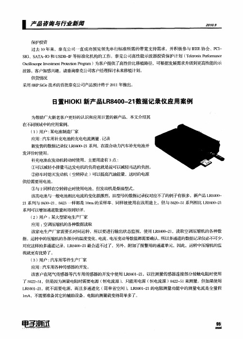
①可以减轻小排量马达发电机的负荷也就是说可 以减轻马达的负担。
②停车时熄灭发动机 ( 空转停止 ) 以提高汽油能量 ,这时的电源 可
供给需要用 电池。
③ 与 2同样在空转停止时使用电池 ,但发动机是柴油型式 。 该类 电池与—般电池相比电流的变化很激烈 ,I型号的数据记录仪对应不了的例子有很多 ,新产品 L 80 - E t R 4 3 2 系列与 83 - 1 43 l 40 2 、82 一样都是 1m 的采样率 、同样被使用在该用途上 ,但与 82 5 系列相 比 L 80 - 1 0s 40 1 - R 4 )2
系列可以增加通道数量而得到好评。
() 2 用户 : 某大型家 电生产厂家 应用 : 空调压缩机的各种数据读取
该 家电生产厂家需要长时间运转 ,所以要进行输出状态监视 ,使用 L 80 - 1 R 402 ,读取空调压缩机的各种数
据。运转中的压缩机的各部分的温度变化 、 电流 、 电压变动等数值都需要确认 , 所以多通道的数据记录仪必不可少,
保护投资
过去 1 0年来 ,泰 克公司一直成功预见领先 串行标 准所需的带宽支持需求 ,并积极 参与 IF . 、P I E .协会 C— F SG、S T -O和 U D — I A AI SB I F等标准化机构的工作。泰 克公 司高性能示波器投资保护计划 ( etn eo ne Tkr i Pr r c o x f ma
Oclcp v t nPoco r r sls enemetretnPo a i o I s o ti g m)为客户提供了高性价 比移植路径 ,可根据发展需求升级到更商 }能的示 生
波器。客户如感兴趣 ,请垂询泰克公司客户经理探讨未来移植计划 。 供货 隋况 采用 8 P ie H G 技术的首批泰克公司产品预计将于 2 1 年推出。 S 01
Fluke DP9800高精度8路数字温度计数据记录仪说明书

M8-Channel Benchtop Digital Thermometer/ Data LoggerFor Thermocouple or RTD Sensors with USB PortDP9800 SeriesU H igh Precision U U SB PC Interface U T hermocouple and RTD Models U B uilt-In Display for Selected Channel or Scanned Channels U R esolution 0.1°C on LCD Display, 0.01°C in Software U S elf-Calibration Feature U S elect °C/°F U P C Software Included for Remote Control and Measure, Logging and Calibration U S imple OperationThe PC software supplied with the instrument allows control,measure and calibration functions.DP9800 shown smaller than actual size.SpecificationsAt an ambient temperature of 20°C Input/Ranges: Thermocouple to IEC 584Type J: -200 to 750°C (-328 to 1382°F)Type K: -200 to 1200°C (-328 to 2192°F)Type T: -200 to 350°C (-328 to 662°F)Type E: -200 to 900°C (-328 to 1652°F)Type N: 0 to 1300°C (32 to 2372°F) Type R: 0 to 1760°C (32 to 3200°F) Type S: 0 to 1760°C (32 to 3200°F) Type B: 300 to 1800°C (572 to 3272°F)Pt100 to IEC751, 3-Wire: -200 to 850°C (-328 to 1562°F)Note: all inputs are non-isolated and thermocouples must be ungrounded style.Accuracy: Thermocouples J, K, T, E, and N, better than ±0.1°C ±0.1% of range zero to span ±0.15% of range -100 to - 200°C (J, K, T, and E)Thermocouples: R, S, and B, better than ±0.1°C ±0.15% of range Linearization: ±0.05°CPt100 Range: Better than ±0.05°C ±0.1% of rangeZero Drift: ±0.01% of span per °CSpan Drift: ±0.01% of span per °C Display: LCD, backlightDisplay Resolution: Thermocouple ranges 0.1°C, Pt100 range 0.01°C User Interface: Front panel key for channel number or auto-scan selection; PC software for all other functionsIndication: Channel number, measured temperature (°C or °F)Reference Junction: Automatic, accurate referenceSelf Calibration: User facility incorporated; the instrumentauto-calibrates on every A/D cycle Sensor: Open circuit upscale indication, detection and indication (independent alarms should be used for process safety if required)Ambient Operating Temperature: 0 to 50°C (32 to 122°F)Storage Temperature: -20 to 70°C (-4 to 158°F)Input Terminations: 8 x thermocouple, mini connectorsTerminal Blocks: 8 x Pt100PC Interface: USBPower Supply: 6 Vdc (5.5 to 9.0V) via universal mains adaptor (supplied), 120 to 250V , 50/60 HzLogging Interval: 5 second to 1 hourThe DP9800 Series thermometer can be used in conjunction with a PC to provide accurate, versatile 8 channel thermocouple andPt100 RTD temperature measure-ments, scanning and logging of measured values. It can also be used as a “stand alone” indicator/logger and incorporates a digital backlit LCD display of measured temperature.The built-in self-calibration facility for the DP9800-TC thermocouple model is a rapid and convenient method for on-site calibration and does not require any additional equipment other than a special, external link.Self-calibration of Pt100 ranges is equally simple and uses plug-in precision resistors.The DP9800 is designed toprovide exceptional stability with high measurement resolution and represents an ideal crossover between plant practicality and laboratory performance at a very competitive price.Ordering Examples: DP9800-TC, 8-channel thermocouple digital thermometer/data logger. OCW-3, OMEGACARE SM extends standard 2-year warranty to a total of 5 years.A ADP9800 shown smaller than actual size.。
Z80监控器使用说明(2023年9月)-la
Z80 Monitor Release 09.2023TRACE32 Online HelpTRACE32 DirectoryTRACE32 IndexTRACE32 Documents ......................................................................................................................ICD In-Circuit Debugger ................................................................................................................Processor Architecture Manuals ..............................................................................................Z80 ............................................................................................................................................Z80 Monitor (1)Brief Overview of Documents for New Users (3)Warning (5)Quick Start of the Z80 ROM Monitor (6)Troubleshooting (8)FAQ (8)Basics (9)Monitor Features9 Monitor Files9 Address Layout10 Configuration11Emulation Modes (12)SYStem.CPU CPU type12 SYStem.Mode Establish the communication with the CPU12General SYStem Settings and Restrictions (13)General Restrictions13 SYStem.Option.BrkVector Breakpoint trap13 SYStem.Option.BASE Base address of internal registers13Using the MMU for Z180 (14)Memory Classes (16)Version 10-Oct-2023 P:000D75\\IARZ80\iarz80\sieve+97........... MIX AI E::w.d.laddr/line code label mnemonic commentP:000D70AF xor aP:000D71ED42sbc hl,bcP:000D73381E jr c,0D93; c,?0176{491flags[ k] =FALSE;P:000D750E00 ?0178: ld c,0 ; c,0P:000D772111C2ld hl,0C211; hl,flagsP:000D7A DD5EFC ld e,(ix-4); e,(ix-4) E::w.v.f /l/c E::w.rj =15CY_A0BC800F SP >0000 {N N F2DE 0C40C-06 0003sieve();P/V _B80HL3-04 000F -000sieve()Hc_C0F IX 0C40F-02 0000i =0Zr_D0C4IY2D8FP >C41Fprimz =3Sig _E0C SP 0C407+02 0CDCk =15IFF _I0PC0D75+04 000Fanzahl =0Tsk AF'0+06 0000 Brief Overview of Documents for New UsersArchitecture-independent information:•“Training Basic Debugging” (training_debugger.pdf): Get familiar with the basic features of a TRACE32 debugger.•“T32Start” (app_t32start.pdf): T32Start assists you in starting TRACE32 PowerView instances for different configurations of the debugger. T32Start is only available for Windows.•“General Commands” (general_ref_<x>.pdf): Alphabetic list of debug commands.Architecture-specific information:•“Processor Architecture Manuals”: These manuals describe commands that are specific for the processor architecture supported by your debug cable. T o access the manual for your processorarchitecture, proceed as follows:-Choose Help menu > Processor Architecture Manual.•“OS Awareness Manuals” (rtos_<os>.pdf): TRACE32 PowerView can be extended for operating system-aware debugging. The appropriate OS Awareness manual informs you how to enable theOS-aware debugging.WarningNOTE:Do not connect or remove probe from target while target power is ON.Power up: Switch on emulator first, then targetPower down: Switch off target first, then emulatorQuick Start of the Z80 ROM MonitorStarting up the ROM Monitor is done as follows:1.Select the device B: for the ROM Monitor.b:2.Power the system down (optional).sys.dThis instruction is necessary when the system is restarted. When the system is active while you try toreinitialize it, you get an error message.3. Set the CPU type in the ROM Monitor program to load the CPU specificsys.cpu z804.Map the EPROM simulator. The mapping of the EPROM simulator is described in the section“Mapping the EPROM simulator”.5.Load the monitor program. Usually the monitor program runs at address 0 in the ROM area.d.load.b romz80.bin /ny6.Configure the Monitor program. The processor type is required for startup. Other parameters areoptional.d.s 0x400 0x0; for Z80 processor7.Load the program.d.load.u iarz80.dbgThe format of the Data.LOAD command depends on the file format generated by the compiler. Thecorresponding options for all available compilers are listed in the compiler list. A detailed descriptionof the Data.LOAD command is given in the Emulator Reference Manual.8.Set the polarity of the Reset and NMI signal according to your target. The NMI signal is optional, it can be used to interrupt the program.9.Start the ROM Monitor. If the RESET output of the ESI is not connected you must press the RESET button on your target after entering this command.A typical start sequence is shown below:The start up can be automated using the programming language PRACTICE.x.respol -x.nmipol -x.nmibreak onSYStem.Up; the EPROM is in the addressrange 0x0--0x7fff ; the RAM is in the addressrange 0x8000--0x0ffff b:sys.d winclear map.resmap.rom 0x0--0x7fff d.load.u iarz80.dbgd.load.b romz80.bin /ny x.respol -x.nmipol -x.nmibreak on SYStem.Up; select the Debugger device ; switch the system dow ; clear all windows; map the EPROM simulator; part of EPROM after internal registers ; load the application; overload is with the monitor; adapt the polarity of RES and NMI; enables the connection of the NMI signal ; power the system upTroubleshooting No information available. FAQEPROM Simulator Error on Data Modification Ref: 0056Why does the ROM monitor crash after modification of EPROM?Check that there is enough space left on the stack. See also "Restrictions for Stack Requirements".Step or Breakpoint FailsRef: 0061Why does single step or breakpoint not work?Check that there is enough space left on the stack before and after the execution of the instruction. See "Restrictions for Stack Requirements". Make sure that the single step and INT3 vector (1 + 3) are valid and point to the correct monitor entry.Stepping Fails when Executing MOV SP,xxxRef: 0062Why does stepping fail, when executing a MOV SP,xxx instruction?Check that there is enough space left on the stack before and after the execution of the instruction. See "Restrictions for Stack Requirements".Check that the value for the CP is within limits for the CPU and that the register space is not being overwritten by the stack. See "Restrictions for Stack Requirements".BasicsMonitor FeaturesThe monitor requires no stack during startup and memory operations. A valid stack is only required for modifications in the EPROM while the monitor is running (Hot Patch) and for single step and go commands.This allows to use the monitor even when the stack is not valid. External RAM memory is not required during startup and for memory operations. This allows to use the monitor also on not fully functional hardware. The NMI pin of the EPROM Simulator can be used to manually stop the target program. The monitor fullysupports bank switching (breakpoints, memory access, symbols). The monitor can operate also when the EPROM is not always visible, i.e. is one of the banks.Monitor FilesThe 'romz80' monitor is for Eprom Simulator solutions, while the 'romz80e' monitor is used as foreground monitor for Emulators. By using a foreground monitor the target program can be single stepped without stopping the target processors interrupts or DMA transfers. Both monitors have the same source file'romz80.asm'. This source file should not be modified, it is only included for reference purposes. There are to possibilities to include the monitor in the application: loading the '.bin' by the Eprom Simulator or linking the '.src' file together with the application. The '.src' files contain only the monitor code, a correspondingconfiguration table must be included in the target program.Address LayoutThe Rom Monitor is freely relocatable in the whole address space by reassembling the source. Thecommunication area for the Eprom Simulator is located at the fixed address 1000 to 1FFF.The monitor program consists of three parts:•Vector Table•Configuration Table•Monitor Program CodeThe '.bin' and '.asm' files contain all three parts of the monitor. The address layout of the default monitor is as follows:0x0000--0x03FF ; Vector Table0x0400--0x041F ; Configuration Table0x0420--0x0FFF; Monitor CodeFor the first tests of a software, the '.bin' files can be loaded with vector and configuration table. When the vector table becomes part of the application, it is not loaded with the monitor. Instead the table is setup according to the application (the table may also reside in RAM). Some vectors must be set up to point into the monitor program code. The entry points are located at the beginning of the monitor.vec offs ent usage00000+20Reset (optional, can also go to application)38038+30Breakpoint T rap, (used for breakpoints, can be changed)66XXX+30Manual Break (optional).....+40Any unused vector may be handled by the monitorThe breakpoint trap vector can be configured by the SYStem.Option.BrkVector command. The default is vector 38.ConfigurationThe configuration table of the monitor must always be located directly before the monitor code. The default location used in the binary files is 400 (hex).•Processor core type (byte at offset 00H):00 = Z80 (default)01 = Z180 (NOTE: Requires also SYStem.CPU Z180 and MMU.ON commands)•Z180 MMU address (byte at offset 01H):38 or 78 or 0b8 or 0f8•Monitor Interrupt Level (byte at offset 04H)00 = all interrupts enabled in monitor01 = all interrupts locked in monitor•Set target bank (four jumps at offset 0cH,10H,14H,18H)•Get target bank (jump at offset 1cH)Emulation ModesSYStem.CPU CPU type Format:SYStem.CPU <mode><mode>:Z80 | Z180 | Z181 | Z182Selects the processor type. The ROM debugger requires also a modification in the debug monitor fordifferent processor types.SYStem.Mode Establish the communication with the CPU Format:SYStem.Mode <mode><mode>:DownNoDebugGoUpDefault: Down. Selects the target operating mode.Down The CPU is in reset. Debug mode is not active. Default state and state after fatalerrors.NoDebug The CPU is running. Debug mode is not active. Debug port is tristate. In thismode the target should behave as if the debugger is not connected.Go The CPU is running. Debug mode is active. After this command the CPU can bestopped with the break command or if any break condition occurs.Up The CPU is not in reset but halted. Debug mode is active. In this mode the CPUcan be started and stopped. This is the most typical way to activate debugging.If the mode “Go” is selected, this mode will be entered, but the control button in the SYStem window jumps to the mode “UP”.General SYStem Settings and Restrictions General RestrictionsSYStem.Option.BrkVectorBreakpoint trap Defines the rst number used for breakpoints and single stepping. The default is RST 38.SYStem.Option.BASEBase address of internal registers The SYStem.Option.BASE defines the base address of the internal registers.Stack Memory The ROM debugger needs 32bytes of memory on the current stack.The stack is not required for starting the Monitor and memory reador modify commands. Modification of the EPROM while the monitoris running (Hot Patch) requires 40 bytes on the stack.CBAR/CBR/BBR Access(Z180)These registers should NOT be accessed by Data.SET commands.CBAR value (Z180)The address between 0000 and 1FFF must be COMMON0 area.Format:SYStem.Option .BrkVector <trap >Format:SYStem.Option .BASE <address >Using the MMU for Z180This command and the commands MMU support the built-in MMU of the Z180 processors.The analyzer and all memory systems and breakpoints are based on the physical address. The display in the analyzer can be both physical or logical addresses. A logical address can have two formats: smaller than 64K or larger. Smaller addresses are assumed to be an logical address as seen by the CPU in the current MMU configuration. If an address is larger than 64K, the address bits A16 to A23 define the bank base address used for the BBR or CBR register. Logical above 64K addresses should only be used, if the MMU registers were already setup. The following schematic shows these relations for some examples: preset: CBAR=84,BBR=10, CBR=20logical address:504567(Hex)16 bitCBR/BBR =50logical CPU address-->physical address:54567logical address:001567(Hex)16 bitcurrent-mmu logical CPU address-->physical address:1567logical address:004567(Hex)16 bitcurrent-mmu logical CPU address-->MMU Bank Area-->physical address:04567+BBR10---=14567logical address:00c d e f(Hex)16 bitcurrent-mmu logical CPU address-->COMMON1 Area-->physical address:0cdef+CBR+20---=2cdefT o activate the correct address translation for breakpoints, the MMU command must be activated. The following example loads a banked application:mmu.offmap.rom 0x0--0x7ffff...mmu.ond.load.u iarz180.dbgThe next example loads a banked application in two logical units: CBAR=84, CBR=0, BBR=10 or 20mmu.resetsymbol.resetmap.rom 0x--0x7ffff…mmu.create 0x104000--0x107fffmmu.create 0x204000--0x207fffmmu.ond.load.b bank1.cod 0x104000 /nosymbold.load.b bank2.cod 0x204000 /nosymbold.load.b common.cod 0x2000 /nosymbold.load.sym bank1.sym /noclearsymbol.reloc p:100000 0x4000--0x4fffd.load.sym bank2.sym /noclearsymbol.reloc p:200000 0x4000--0x4fffd.load.sym common.sym /noclearMemory ClassesMemory Class DescriptionD DataP ProgramC Memory access by CPUE Emulation memory accessA Absolute (physical) memory access。
红外热像仪期间核查方法的研究

红外热像仪期间核查方法的研究欧阳宇佳 詹佳才 郭嘉荣 叶凯华广东产品质量监督检验研究院 广东佛山 528300摘要:期间核查是一种常见的实验室设备质量控制手段,介绍了常见的期间核查方法,并根据实验室检测条件以及红外热像仪的实际使用场景,制订了恒温光伏组件作为测试对象,温度采集器测试结果作为核查标准,对应用于光伏电站测试的红外热像仪进行示值误差和测温一致性进行期间核查的方法。
核查结果表明:该设备在计量有效期内保持校准状态,可继续使用。
关键词:期间核查 测量设备 红外热像仪 光伏电站中图分类号:TN21文献标识码:A文章编号:1672-3791(2024)01-0086-04Research on the Intermediate Check Method of Infrared ThermalImagersOUYANG Yujia ZHAN Jiacai GUO Jiarong YE KaihuaGuangdong Testing Institute of Product Quality Supervision, Foshan, Guangdong Province,528300 China Abstract:The intermediate check is a common quality control method for laboratory equipment. This paper in‐troduces common methods for intermediate checks, and according to laboratory testing conditions and the actual application scenario of infrared thermal imagers, develops a method for the intermediate check of the indication er‐ror and temperature measurement consistency of infrared thermal imagers used for PV station testing with constant temperature PV modules as test objects and the test results of temperature collectors as check standards. The check results confirm that the equipment remains calibrated within the validity period of measurement and can continue to be used.Key Words: Intermediate check; Measuring equipment; Infrared thermal imager; Photovoltaic station期间核查(intermediate checks)是根据规定程序,为了确定计量标准、标准物质或其他测量仪器是否保持其原有状态而进行的操作[1]。
日置 热流数据采集仪 LR8432 说明书
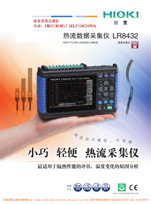
测量项目※图片中的热流传感器为选件另售最适用于隔热性能的评估,温度变化的原因分析因分析最适用于隔热性能的评估温度变化的原因小巧 轻便 热流采集仪热流动可视化,可掌握。
热流数据采集仪HEAT FLOW LOGGER LR8432数据采集仪LR8432热流动可视化,可掌握。
热流定义温度变化时,势必包含热能的移动。
热能是温度变化所释放的能量,与水和电相同由高到低的转移。
这种热能移动的程度即用“热流”来表示,单位时间单位面积流动的热能量表示为(单位:W/m 2)。
温度体现结果,热流体现过程。
使用热电偶和温度记录法仅能测量温度,对于温度的变化过程(正在发热或正在吸热)却全然不知。
使用“热流传感器”,将热能量移动和量可视化,可作为温度变化的先行指标。
测量热能,对于更高精度的空调控制或针对产品研发的热能策略具有重大意义。
建筑·住宅设备环保屋的评估隔热·断热性能的评估暖房效率的评估地暖的评估了解量的变化通过数值和波形来了解热的量。
能够通过可视化热量来评估隔热性能,弄清热能流入流出的地方。
电气·机械家电的隔热性能的评估冷暖空调的评估灶具的评估研发热能的控制热电转换蓄热,未利用热(排热)的利用汽车对从引擎箱或排气管流入车内的热能进行评估车内空调的评估汽车零件发热·放热的评估农业·土木地热的评估农业大棚的温热评估4行驶中降低温度▲ 放热措施停止后降低温度▲隔热措施即最适合的热能策略是行驶中 ▲ 发热中停止后 ▲吸热中停止时热流表呈现从+到-的变化热流W/m 2时间时间+-行驶中停止状态行驶中停止状态+部分……发热中-部分……吸热中停止时停止时温度发生变化肯定是有理由的。
热流测量,能够使原本不透明的理由明确化。
温度上升的原因不明,很难做出相应的热能策略通过区分发热和吸热,可给出最适合的热能策略通过比较热流大小,可选择隔热性能好的建材可判断出适用于墙角和地面的室外装修或纱窗,地板等室内装修的最适合的隔热材料热流 小热源热流 大即热流 大▲ 隔热性 低热流 小 ▲隔热性 高明确了温度的上升理由,即可做出最合理的隔热·放热设计。
数据记录仪LR8400(CH)
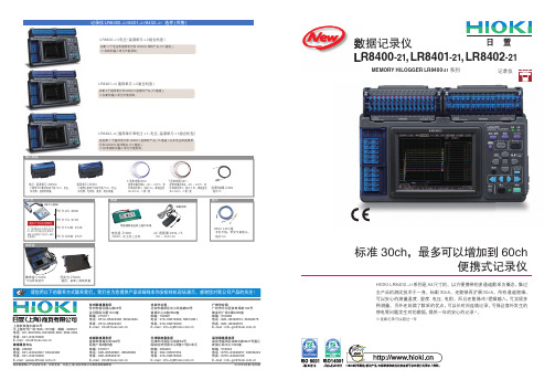
数据记录仪LR8400-21,LR8401-21,LR8402-21MEMORY HiLOGGER LR8400-21 系列记录仪具体数据等以产品实际为准,如有变动,日置(上海)商贸有限公司具有最终解释权2010年4月第1次印刷请您用以下的联系方式联系我们,我们会为您提供产品详细样本和安排样机现场演示。
感谢您对我公司产品的关注!成都联络事务所成都市顺城大街308号冠城广场8楼R座邮编 : 610017电话 : 028-********, 86528882 传真 : 028-********E-mail : info@维修服务中心邮编 : 200021电话 : 021-********, 63343308 传真 : 021-********E-mail : weixiu@天津联络事务所天津市河西区马场道59号国际经济贸易中心B座17层C单元邮编 : 300203电话 : 022-********传真 : 010-********E-mail : info-bj@苏州联络事务所苏州市新区狮山路35号金河国际大厦1612室邮编 : 215011电话 : 0512-********, 66324383传真 : 0512-********E-mail : info@ 广州分公司广州市天河区体育西路103号维多利广场A塔3206室邮编 : 510098电话 : 020-********, 38392676传真 : 020-********E-mail : info-gz@ 北京分公司北京市朝阳区东三环南路58号富顿中心A座2602室邮编 : 100021电话 : 010-********, 58674081传真 : 010-********E-mail : info-bj@ 深圳联络事务所深圳市福田区深南中路3027号嘉汇新城汇商中心1922室邮编 : 518033电话 : 0755-********, 83039243传真 : 0755-********E-mail : info-gz@上海市淮海中路93号大上海时代广场1608-1610室 邮编 : 200021电话 : 021-********, 63910096, 0097, 0090, 0092传真 : 021-********E-mail : info@ HIOKI LR8400-21系列是A4尺寸的。
飞利浦 VTR8400 音视频记录仪 使用手册说明书
6 ZH
中文
2 重要须知
导致交通意外,且违反相关法律法规。
2.1 安全
小心 • 特别声明:使用本产品前请仔细阅读本说明书,如因人为
操作或不可抗力因素而导致数据丢失,本公司一概不予负 责。特别提醒用户小心操作,注意将资料另外备份。 • 显示图像仅作参考。飞利浦保留更改颜色 / 外观 / 设计 / 参数 / 产品功能的权利,硬件、软件、APP 如有更新,恕不 另行通知。
(4) 在黑夜或者光线暗的环境下录像时,按下“ ”键,照明 灯将打开,补充光源 , 再按“ ”键关闭白光灯。
(5) 录音和录像可一键切换,同时保存文件。 录像参考界面如下图所示:
录像时间 白光灯 切换摄像头 缩小
录像/停止 放大 分辨率 SD卡容量
ZH 13
注意 • 电池标记符显示空格时,表明低电。如果正在录像或者录音,
33
26
19 背夹的装取
34
27
19.1 安装背夹
34
19.2 取下背夹
34
29
20 背夹的佩戴方式
35
30
30
21 常见问题
36
30
21.1 无法启动执法仪
36
30
21.2 显示时间 / 日期不正确
36
21.3 拍照 / 录像图像模糊,不清楚
36
21.4 执法仪无法录音或者录像
36
31
21.5 执法仪无法播放录音或者录像
用者编号等信息,无法剪辑,更具法定证据效力。 • 超长文件名,所有录像文件的文件名都包含产品编号、时间、
使用者编号等信息,方便数据存档、检索。 • 录像资料自动分割保存,防止错误操作造成资料丢失。 • 外置存储卡,最大支持 256G。 • 高清扬声器:采用高品质振动喇叭,无论播放录音文件或录
磷酸铁锂动力锂离子电池穿刺实验

磷酸铁锂动力锂离子电池穿刺实验金标;周明涛;刘方方;安治文【摘要】In order to evaluate safety problem during internal short circuit of lithium iron phosphate (LiFePO4) power Li-ion battery,temperature on the surface of battery with ceramic cap,open circuit voltage and inrush current were analyzed by the nail penetration test of single and parallel connection battery respectively.No matter what the connection and nailing position were,the monitored temperature on the surface of battery near positive pole ear was higher than one in other places during nail test,which could reach the maximum value of 442.5 ℃,increased rapidly in the early stage and then decreased gradually,the bigger electrolyte concentration caused the greater internal resistance.The smaller nailing contact resistance caused the higher temperature on the surface of battery,then instantaneous charged current of the nailed battery in parallel connection became lager,the maximum value of which could reach 256.0 A.The safety performance of the battery with ceramic cap was improved.%为评估磷酸铁锂(LiFePO4)动力握离子电池内短路时的安全问题,采用陶瓷顶盖结构的单体电池与1+5只并联连接电池的穿刺实验,分析电池表面温度、开路电压及涌流变化情况.不论连接方式和穿刺位置如何,均是靠近正极极耳的监控点温度最高,最高可达442.5℃,且前期该处温度迅速上升,后期逐渐降低;电解液浓度越低,电池内阻越大;穿刺接触电阻越小,电池表面温度越高,并联连接的被刺电池瞬间反充电流较大,最大可达256.0 A;电池未出现着火现象,穿刺安全性能得到提高.【期刊名称】《电池》【年(卷),期】2017(047)001【总页数】4页(P23-26)【关键词】磷酸铁锂(LiFePO4);动力锂离子电池;穿刺;内短路;涌流【作者】金标;周明涛;刘方方;安治文【作者单位】广东科技学院机电工程系,广东东莞523083;芜湖佳景科技有限公司,安徽芜湖241002;广东科技学院机电工程系,广东东莞523083;华南理工大学机械与汽车工程学院,广东广州 510641;广东科技学院机电工程系,广东东莞523083【正文语种】中文【中图分类】TM912.9车用大容量动力锂离子电池在穿刺过程中会诱发热安全问题,原因是穿刺引起电池内部短路,穿刺处温度急剧上升,超过内部活性物质的反应温度时,活性物质的化学反应将释放大量的热量,最终导致电池着火、燃烧或爆炸。
FLIR X8400sc热成像相机说明书
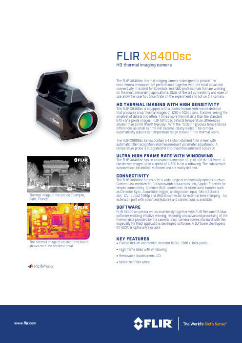
FLIR X8400scHD thermal imaging cameraThe FLIR X8400sc thermal imaging camera is designed to provide thebest thermal measurement performance together with the most advanced connectivity. It is ideal for Scientists and R&D professionals that are working on the most demanding applications. State-of-the-art connectivity and ease of use allow the user to concentrate on the experiment and not on the camera.HD THERMAL IMAGING WITH HIGH SENSITIVITYThe FLIR X8400sc is equipped with a cooled Indium Antimonide detector that produces crisp thermal images of 1280 x 1024 pixels. It allows seeing the smallest of details and offers 4 times more thermal data than the standard 640 x 512 pixels images. FLIR X8400sc detects temperature differencessmaller than 25mK (18mK typically). With the “lock-in” process temperatures differences as small as 1mK will become clearly visible. The camera automatically adjusts its temperature range to best fit the thermal scene.The FLIR X8000sc Series contain a 4 slots motorized filter wheel with automatic filter recognition and measurement parameter adjustment. A temperature probe is integrated for improved measurement accuracy.ULTRA HIGH FRAME RATE WITH WINDOWINGThe FLIR X8400sc has an adjustable frame rate of up to 106 Hz full frame. It can deliver images up to a speed of 4,500 Hz in windowing. The sub-sample windows can be arbitrarily chosen and are easily defined.CONNECTIVITYThe FLIR X8000sc Series offer a wide range of connectivity options such as Camera Link medium for full bandwidth data acquisition, Gigabit Ethernet for simple connectivity, Standard BNC connectors for often used features such as Detector Sync, Acquisition trigger, analog lockin input, MicroSD-cardslot, DVI-output 1080p and IRIG-B connector for external time stamping. An extension port with advanced features and connections is available.SOFTWAREFLIR X8400sc camera works seamlessly together with FLIR Re s earch I R Max software enabling intuitive viewing, recording and advanced processing of the thermal data provided by the camera. Each camera comes standard with this especially for R&D applications developed software. A Software Developers Kit (SDK) is optionally available.KEY FEATURES• Cooled Indium Antimonide detector (InSb): 1280 x 1024 pixels • High frame rates with windowing • Removable touchscreen LCD• Motorized filter wheelThermal image of the Arc de Triomphe, Paris, France.This thermal image of an electronic boardshows even the smallest detail.Imaging Specifications NASDAQ: FLIRSpecifications are subject to change without notice©Copyright 2014, FLIR Systems, Inc. All other brand and product names are trademarks of their respective owners. The images displayed may not be representative of the actual resolution of the camera shown. Images for illustrative purposes only. (Created 10/14) RND_022_ENTouchscreen LCD- microSD - USB device - DVICAMLINK Base/MediumGigEDigital & Analog I/O's IR RemoteAuxilliary connector Status LEDs Power buttonPORTLANDCorporate Headquarters FLIR Systems, Inc.27700 SW Parkway Ave.Wilsonville, OR 97070USAPH: +1 866.477.3687BELGIUMFLIR Systems Trading Belgium BVBALuxemburgstraat 22321 Meer BelgiumPH: +32 (0) 3665 5100SWEDENFLIR Systems AB Antennvägen 6, PO Box 7376SE-187 66 Täby SwedenPH: +46 (0)8 753 25 00NASHUAFLIR Systems, Inc.9 Townsend West Nashua, NH 06063USAPH: +1 603.324.7611UKFLIR Systems UK 2 Kings Hill Avenue Kings HillWest Malling - Kent ME19 4AQUnited KingdomPH: +44 (0)1732 220 011。
U-SIN-R1000-TKCN2 第2版 有纸记录仪 使用说明书

第一章 产品概述
第一章 产品概述
R1000 系列有纸记录仪以独特的热打印记录方式和先进的微处理器 控制技术,实现了无与伦比的高记录清晰度、高精度、高可靠性、多功 能且便于操作。可连续记录和数字打印。
该仪表的每个通道均可直接选择接收多种热电偶、热电阻、电压和 电流信号,并可对被测信号进行数字显示及进行趋势记录和数字记录, 能在本身打印的 100mm 宽的纸格上同时记录刻度值、时间及每一个信 号的曲线,并将通道号印在各通道的轨迹旁。可通过键盘设定测量信号 种类、小数点位置、显示范围、记录边界、报警值、回差、系统误差的 校正、记录标尺、数据打印间隔、走纸速度、打印深度及时间等参数, 并对所设参数加以保护。广泛应用于医药、石油、化工、冶金、电力等 行业及科研单位。
报警提示符及提示灯
时间显示[在所有输入信号全部关闭情况下]
4. 记录功能:采用进口固定式热敏头,无笔墨消耗,无笔位
误差,抗震动
在 100mm 范围内有 800 个热必做好防雷工程设施:共用接地网进行等电位接地、屏蔽、
合理布线、适当使用浪涌保护器等。 内部某些部件带有高压,非本公司或非本公司认可的维修人
员,请勿打开前方面板,以免发生触电事故。 在进行各项检查前务必切断电源,以免发生触电事故。 请定期检查端子螺钉状况,若发现其松动,请紧固之后再投
7.1 结构特点...........................................................................................19 7.2 安装方法...........................................................................................20 7.3 换纸方式...........................................................................................20 第八章 仪表的保存与维护.......................................................................... 21 第九章 接线方法...........................................................................................22 第十章 仪表的使用注意事项及保修期...................................................... 23 第十一章 使用常见错误分析...................................................................... 24 第十二章 质保及售后服务.......................................................................... 25
东莞联仪多路温度记录仪 SH-8X 8 路 SH-16X 16 路 SH-24X 24 路 SH-3

使用说明书多路温度记录仪SH-8X 8路SH-16X 16路SH-24X 24路SH-32X 32路SH-32X 40路SH-32X 48路SH-32X 56路SH-32X 64路东莞市联仪仪器仪表有限公司Dongguan Lianyi Instrument Co., Ltd.电话:0769-******** 33213581前言感谢您选购本公司的产品,为保证用户能正确使用本产品,请在使用前认真阅读本产品说明书.并对照检查本说明书的装箱清单确认产品和附件.若有不符合请联系本公司或代理商.注意事项1.本说明书内容与仪器配套使用,因版本升级等内容有更改时,恕不另行通知.2.本说明书内容经确认无误,已用最简单的方式来表达用户对说明书的易懂性编写.如发现有不正确或说明不清晰时,请与本公司或代理商联系.3.版本:V1.1警告为了你的人身安全和能正确使用本仪器,请务必遵守本说明书要求进行操作和测量.并严格注意以下安全规定.1.电源与接地保护,本产品工作电源为AC220V供电,打开电源前应确保供电是否与额定电压匹配,并确保电源已接保护地线,以防电击,本仪器外壳已接到电源插座地线端.2.请勿在有爆炸性的环境下操作,以免发生爆炸造成人身伤害.3.请不要自行打开仪器外壳,仪器内部某些地方具有高压电,防止发生触电.4.不允许在带电的情况下插拔接线端子,以免发生触电.5.如果是因为违反安全规定需产生的仪器损坏,本公司不承担任务责任.1.概述本多路温度采集器采用32位高速CPU进行数据处理,采用5寸工业显示屏,支持K J T 型热电偶输入,多种显示方式,使用者能更加直观读取各参数,仪器具有完善的功能、性能优越和操作简单的特点,能满足生产、实验室和研发测量的需求。
广泛应用于照明电器、电动工具、家用电器、电机、电热器具医药、石油、化工、冶金、电力等行业及科研单位等领域生产企业的生产线、实验室、质检部门。
按实户需求还能订制各种测量功能,来满足更高的应用。
L14Q684 网络可连接双页 8路色彩四路监控摄像头产品说明书

Copyright © 2006 LOREX Technology Inc.FAQEnglish Version 1.0MODEL:L14Q684FAQ Guide OverviewFAQ Guide OverviewThe following questions are addressed in this FAQ Guide.1. Why is my DDNS Connection not working?2. What Web Browsers are supported?3. Where do I find my License for the Lorex Player?4. Where do I find my MAC Address?5. Why is my Video not Displayed?If you have any additional questions or technical issues, please contact the Sentinel CCTV Help desk for further assistance at 1-888-425-6739 (Option 1 - 1) or mail your questions to**************************2FAQ Guide Overview31. Why is my DDNS Connection not working?I signed up for the DDNS Service, received my email confirmation and have entered myinformation into my unit, however it is not allowing me to connect - have I entered the information correctly?After registering with the online DDNS Server, you are required to input the information into the unit (by following the instructions provided in email) - by leaving the PASSWORD blank.The password you provided for the DDNS Server site is NOT required for use with your system - this is a password for logging into the site only. Do NOT enter your password - leave this field blank.2. What Web Browsers are supported?I am using Opera, Netscape, Firefox (etc.) and am unable to connect to my unit. Are there limitations on the kind of Web Browswers I can use?The Observation System can only be used with Microsoft Internet Explorer - This unit does not support any other browsers.3. Where do I find my License for the Lorex Player?I have downloaded and installed the Lorex Player from the LorexCCTV website, but it is prompting me for my License Number - where can I get this information?There are 2 different pieces of Information to enter in the Registration License window:• Enter IPSC1110 in the first entry box.• Enter the first 8 digits of the MAC address into the second box.Please see Section 4: Where do I find my MAC Addressfor details on obtaining this information.FAQ Guide Overview4. Where do I find my MAC Address?I need my MAC Address for licensing - where can I find this information?Locate and run the IPEditt.exe application (found on the supplied CD, or downloaded from the Lorex Website at ). The Lorex IPEDIT application will display information about your device, including the MAC Address4FAQ Guide Overview55. Why is my Video not Displayed?I am trying to view video from my Video Network Server, but nothing is appearing onscreen. Are there additional changes I need to make to my system?The settings in Internet Explorer may need to be changed by setting ActiveX to Enabled, and allowing Pop-ups in Internet Explorer (or by disabling any third party popup blocker software).Internet Explorer Settings - Active X ControlsTo correctly load the Web Client Software, the security settings in Internet Explorer may need to be adjusted:1. Open Internet Explorer. Click TOOLS and select INTERNET OPTIONS.2. Select the SECURITY tab, and click the CUSTOM LEVEL button. Change the following settings:• Active X Controls and Plug-ins:z Set ‘Automatic Prompting for Active X Controls’ to Disablez Set ‘Download Unsigned Active X Controls’ to Prompt• Miscellaneous:z Set ‘Allow script-initiated windows without size or position constraints’ toEnable3. Click on APPLY and OK to close the INTERNET OPTIONS window.Internet Explorer Settings - Allowing Pop-UpsThe Web based client software requires the use of Pop-Ups in Internet Explorer. Once the address has been entered into the Address bar, an alert may appear indicating that a Pop-Up window has been blocked:1. Click on the Pop-Up warning on the Internet Explorer Window to access the Pop-Ups drop down menu2. Select ‘Always Allow Pop-ups from This Site’3. A prompt window will appear to Allow the Pop-Up from this site. Select YES.NOTE: If you have a Pop-Up blocker installed, youmay need to disable it prior to loading the Web Client Software.It’s all on the webProduct InformationUser Manuals Quick Start Guides Specification Sheets Software Upgrades Firmware Upgrades Strategic Vista International Inc.VISIT。
- 1、下载文档前请自行甄别文档内容的完整性,平台不提供额外的编辑、内容补充、找答案等附加服务。
- 2、"仅部分预览"的文档,不可在线预览部分如存在完整性等问题,可反馈申请退款(可完整预览的文档不适用该条件!)。
- 3、如文档侵犯您的权益,请联系客服反馈,我们会尽快为您处理(人工客服工作时间:9:00-18:30)。
数据记录仪LR8400-21,LR8401-21,LR8402-21MEMORY HiLOGGER LR8400-21 系列记录仪具体数据等以产品实际为准,如有变动,日置(上海)商贸有限公司具有最终解释权2010年4月第1次印刷请您用以下的联系方式联系我们,我们会为您提供产品详细样本和安排样机现场演示。
感谢您对我公司产品的关注!成都联络事务所成都市顺城大街308号冠城广场8楼R座邮编 : 610017电话 : 028-********, 86528882 传真 : 028-********E-mail : info@维修服务中心邮编 : 200021电话 : 021-********, 63343308 传真 : 021-********E-mail : weixiu@天津联络事务所天津市河西区马场道59号国际经济贸易中心B座17层C单元邮编 : 300203电话 : 022-********传真 : 010-********E-mail : info-bj@苏州联络事务所苏州市新区狮山路35号金河国际大厦1612室邮编 : 215011电话 : 0512-********, 66324383传真 : 0512-********E-mail : info@ 广州分公司广州市天河区体育西路103号维多利广场A塔3206室邮编 : 510098电话 : 020-********, 38392676传真 : 020-********E-mail : info-gz@ 北京分公司北京市朝阳区东三环南路58号富顿中心A座2602室邮编 : 100021电话 : 010-********, 58674081传真 : 010-********E-mail : info-bj@ 深圳联络事务所深圳市福田区深南中路3027号嘉汇新城汇商中心1922室邮编 : 518033电话 : 0755-********, 83039243传真 : 0755-********E-mail : info-gz@上海市淮海中路93号大上海时代广场1608-1610室 邮编 : 200021电话 : 021-********, 63910096, 0097, 0090, 0092传真 : 021-********E-mail : info@ HIOKI LR8400-21系列是A4尺寸的。
以方便携带的多通道数采为概念,集过去产品的测试技术于一身。
标配30ch,还能够再扩展30ch。
所有通道绝缘,可以安心的测量温度、湿度、电压、电阻。
而且还能脉冲/逻辑输入,可实现多种测量。
另外还延续了数采的优点,可以长时间连续记录,可保证意外发生的停电等问题发生时的数据,提供一年的安心的记录※。
※连续记录可以超过一年标准30ch,最多可以增加到60ch便携式记录仪通讯CF 卡附带PC卡适配器购买PC卡时的注意事项请务必使用公司提供的PC 卡。
使用除本公司选件以外的PC卡时,有可能无法正常保存、读取,此种情况下本公司一概不负其责任。
电源电池组Z1000NiMH,在主机上充电可直接装在主机上进行充电携带盒携带盒C1000可以收纳选件固定台Z5000壁挂,桌面上斜面放置输入相关K 型热电偶9810温度测量范围在-180~200℃,容许等级范围2,线长5m,裸线直径Φ0.32mm,5根/套T 型热电偶9811温度测量范围在-180~200℃,容许等级范围2,线长5米,裸线直径Φ0.32mm,5根/套PC 卡2G 9830PC 卡1G 9729PC 卡512M 9728PC 卡256M 97279642 LAN 线非交叉线,带交叉转换头,线长5m湿度传感器Z2000线长3m电压·温度单元LR85002极带M3螺丝的端子板15ch,电压、热电偶、温度的测量。
通用单元 LR85014极带压紧端子的端子板15ch,电压、热电偶、电热阻、温度、阻抗测量。
记录仪LR8400-21/8401-21/8402-21 选件(另售)LR8400-21(电压·温度单元×2组合机型)标配2个电压和温度单元和LR8500相同产品(15通道)。
※标配的输入单元不能拆卸。
LR8401-21(通用单元×2组合机型)标配2个通用单元和LR8501是相同产品(15通道)。
※标配的输入单元不能拆卸。
LR8402-21(通用单元和电压×1,电压、温度单元×1组合机型)各标配1个通用单元和LR8501是相同产品(15通道)以及电压和温度单元和LR8500是同等品(15通道)。
※标准装配的输入单元不能拆卸。
AC 适配器 9418-15100~240V AC标配附件23温度/湿度的测量和记录测量并记录各种变压转换器的输出(直流电压)电池的各个单元的电压测量中所必须的高压电压、绝缘输入电阻值的测量和记录电压测量(仅限直流)热电偶 温度测量,湿度测量热电偶湿度 rh · 根据各种热电偶的测量温度不同,有30ch 对应· M3螺钉输入端子,可以固定细小的热电偶·使用专用电流传感器,可以测量湿度30ch (Z2000,选件)※传感器用电源使用左侧的带M3螺丝的端子板※通用输入端口,用任何一侧的带M3螺丝的端子板都可测湿度· 最多30ch 输入※输入部分的功能/端口的组合,LR8400-21,LR8401-21,LR8402-21不同· 所有通道绝缘输入※主机和模拟输入之间的对地最大电压是AC,DC300V※通道之间的最大电压是DC300V和高压。
(M3螺钉输入端子时是DC250V)脉冲累积/回转·8ch 输入(数字输入和各通道切换)·耗电量累积、流量累积·输入时主机和GND 共地※通过M3螺丝输入端子直接连接脉冲累积/回转·8ch 输入(数字输入和各通道切换)·马达、钢钻等的转数不均匀测量等·输入时主机和GND 共地※通过M3螺丝输入端子轻松连接数字·8ch 输入(脉冲输入各通道切换)·每个记录间隔记录1或0·输入时主机和GND 共地※通过M3螺丝输入端子轻松连接脉冲(累积)测量数字输入脉冲(转数)测量因为需要评估被测量物体的电阻变化,因此可以记录电阻。
※4端子法测量,分辨率0.5mΩ~,测量电流1mA。
温测量电池电阻测电推荐点电多种测量热电阻电阻热电阻 温度/电阻测量· 通用型输入对应的是指根据热电阻(Pt100/JPt100)的温度· 通用型输入对应的是电阻值测量(4线式)※所有带M3螺丝的端子板都无法测量■ 发挥A4尺寸的作用因为主机仅A4尺寸大小,便于携带到各种作业现场进行测量。
■ 可以用于车载数据收集符合JIS 汽车振动标准。
推荐用于车载时收集数据。
※JIS D1601:1995 5.3(1) 1种:轿车,条件:A 类用件可以用于以下方面面向燃料电池、电动车电池等开发领域■ 耐高压■ 高速采样■ 多通道测量■防止地球变暖的环境测量■ 燃料电池材料开发能源领域■ 汽车研发车载零件评价■设备的维护、检查■厂区监测■电子产品的评估■电子零件电阻值的评估●对地间最大额定电压AC、DC 300V●可增加输入端口间最大输入电压 DC±100V● 电温度单元部分的通道间最大电压:DC 250V● 通通道间最大电压:DC 300V45■ 可使用U盘可以使用U盘进行存储。
可以直接将测量数据实时的保存至U盘中。
要将数据复制到电脑中的话,使用U盘也很方便!※可以将数据实时保存至U 盘中,不过要保证实时保存的数据无误,推荐使用HIOKI 原配CF 卡。
■ 在实时记录时可以更换存储媒介有客户提出“希望在保持测量的同时,能够取出之前记录的数据”。
实时记录数据至U 盘和CF 卡时,可以保持测量的同时更换存储媒介。
※更换新的媒介,记录时间设置为最快时,请在2分钟以内完成更换。
推荐点媒介更换仅30个模拟通道记录时(无脉冲测量、报警输出和波形计算功能)记录时间LR8400-21内存(16MB)256MB 512MB 1GB 2GB 10ms15个模拟通道以下有效46m 12h 25m1d 00h 51m 2d 01h 42m 4d 03h 25m 20ms 30个模拟通道以下有效1h 33m 1d 00h 51m 2d 01h 42m4d 03h 25m8d 06h 50m50ms3h 53m2d 14h 08m5d 04h 16m 10d 08h 33m 20d 17h 06m100ms 7h 46m 5d 04h 16m 10d 08h 33m 20d 17h 06m 41d 10h 12m200ms 15h 32m 10d 08h 33m 20d 17h 06m 41d 10h 12m 82d 20h 24m 500ms 1d 14h 50m 25d 21h 22m 51d 18h 45m 103d 13h 30m 207d 03h 01m 1s 3d 05h 40m 51d 18h 45m 103d 13h 30m 207d 03h 01m 414d 06h 03m 2s6d 11h 20m 103d 13h 30m 207d 03h 01m 414d 06h 03m- 略 -5s 16d 04h 21m 258d 21h 47m 517d 19h 34m - 略 -- 略 -10s 32d 08h 43m 517d 19h 34m - 略 -- 略 -- 略 -20s 64d 17h 26m - 略 -- 略 -- 略 -- 略 -30s 97d 02h 10m - 略 -- 略 -- 略 -- 略 -1min 194d 04h 20m - 略 -- 略 -- 略 -- 略 -2min 388d 08h 40m- 略 -- 略 -- 略 -- 略 -5min ~- 略 -- 略 -- 略 -- 略 -- 略 -※ 记录通道数越少,最长记录时间越长。
※ CF 卡的实际容量比标明的容量小,而且未包含波形文件内前面的部分,因此请按照9成的程度来估算上述记录时间。
※ 表格中省略了大大超过1年的时间。
※长时间连续记录时,推荐使用HIOKI原装CF 卡。
■ 可使用U 盘用于1年以上长时间准确记录电子数据推荐点媒介保存■ 可使用CF 卡若要长时间的记录重要数据,推荐使用符合工业标准的HIOKI 原装CF 卡。
※若使用非HIOKI 原装CF 卡,则无法保证正常操作。
媒介的记录时间■ 抗干扰性提高由于超过采样速度因此使用数字滤波功能,以记录减少之前很难屏蔽的变频器的开关干扰和50/60Hz 的谐波干扰的影响。