TP1000数据记录仪说明书
MF1000流量积算记录仪使用说明书

II
前言
危
险
请勿在易燃易爆气体或有蒸汽的场所使用记录仪。 记录仪可正常工作于一般场合,若记录仪的故障可能 导致重大事故或损坏其它设备,需设置紧急停止电路 和保护回路。 运行前务必确认供给电压是否与额定电压一致。 为防止触电、误操作、显示不正常或测量出现较大误 差,务必进行良好的接地保护。 务必做好防雷工程设施:共用接地网进行等电位接地、 屏蔽、合理布线、适当使用 SPD 浪涌保护器等。 安装接线完毕后请安装上端子盖,以免发生触电事故。 内部某些部件带有高压,非我公司或非我公司认可的 维修人员,请勿打开前方面板,以免发生触电事故。 在进行各项检查前务必切断电源,以免发生触电事故。 需定期检查端子螺钉和安装螺钉状况,若发现其松动, 请紧固之后再投入使用。 绝不允许擅自拆卸、加工、改造或修理记录仪,否则 可能导致其动作异常,触电或火灾事故。 请用干燥棉布擦拭记录仪,不可使用酒精、汽油或其 它有机溶剂。谨防各种液体溅到记录仪上,若记录仪 落入水中,请立即切断电源,否则有漏电、触电乃至 火灾事故发生。 需定期检查接地保护和保险丝状况。若您认为接地保 护和保险丝等保护措施不够完善,请勿运行。 记录仪壳体两侧通风孔须保持通畅,以免由于高温发 生故障、动作异常、寿命缩短和火灾。 请严格按照本说明书的各项说明进行操作,否则可能
III
流量积算记录仪
损坏记录仪的保护装置。
IV
前言
警
示
பைடு நூலகம்
开箱时若发现记录仪损坏或变形,请勿使用。 安装时避免灰尘、线头、铁屑或其它物质进入记录仪, 否则会发生动作异常或故障。 连接热电偶时,请勿使用补偿导线以外的线材,否则 会造成显示误差或动作异常。 连接热电阻时,需用 3 根阻值相等且小于 10Ω的导线, 否则会造成显示误差或动作异常。 运行过程中,如需进行修改组态、信号输出、启动、 停止等操作,应充分考虑操作安全性,错误操作可能 导致记录仪和被控设备发生故障乃至损坏。 记录仪各部件有一定的寿命期限,为保证长期使用, 务必进行定期保养和维护。 报废本产品时,按工业垃圾处理,避免污染环境。
TPK计数器使用说明书

其提示语【Save new data?】将会闪动。 此时用户可以按[CANCEL]键取消参数设置,返回上述的界面 1,如果用户按[OK] 键,本机将保存用户设定的参数进入密码设置界面。 在上述的设置过程中,如果按[SET]键,本机将进入密码设置界面 密码设置 进入密码设置功能后,本机将显示如下界面:
【SysSw5[N]】表示是否启用反转螺丝数目减 1 功能; 此开关的对应提示语句为“Reverse screw No.-1?”
用户可以使用[▲]键及[ ]键来改变选择,并且使用[OK]键来确认并进入下一个参
数的设置功能。当第 3 个参数设置完成并确认后,本机将显示下图所示的提示界 面:
其提示语【Are you sure?】将会闪动。 此时用户可以按[CANCEL]键返回上述的界面 1,也可以按[OK]键保存参数并进行 相关的操作。 当允许使用外部信号时,工作界面的剩余螺丝数目将会被重新置为设置的每组螺 丝锁付数目(Screws No./Set),并且切断电批的工作电源,直到本机接收到外部 输入信号为止;在完成一组螺丝锁付后,本机同样会切断电批工作电源,等待外 部输入信号。 当单独电源功能被激活时,本机将做为一个普通的电源供应器,关闭所有的计数 功能。此时本机界面如下:
记录仪说明书
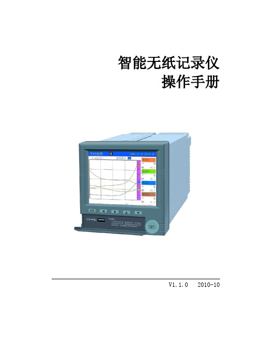
智能无纸记录仪操作手册V1.1.0 2010-10前言非常感谢使用本公司生产的无纸记录仪。
本手册提供对无纸记录仪使用时关于安装、运行操作、参数设计、故障诊断等方面的方法,在使用无纸记录仪之前,敬请仔细阅读本手册并妥善保管在便于随时翻阅处。
因技术升级而作的更改不再另行通知,请以实物为准。
装箱清单注意事项◆本仪表适用于一般工业场合,如有特殊的使用要求请另行设置保护装置◆为保证仪表安全工作,请使用额定电压的供电电源,正确接线,妥善接地,接通电源后,请不要触摸仪表后部的接线端子,以防触电◆为了您和仪表的安全,请勿带电安装◆本无纸记录仪是非安防爆产品,切勿在有可燃或爆炸性气体的环境中使用◆记录仪的安装位置请保证通风顺畅◆仪表在靠近电源动力线,强电场,强磁场或交流接触器干扰的场合应采取相应的屏蔽措施◆为避免测量误差,传感器是热电偶时,请使用相应的补偿导线传感器是热电阻时,要使用三根规格相同而且电阻值小于10Ω的铜导线,否则会造成测量误差◆擦拭仪表时请用干净软布,切勿蘸取酒精、汽油等有机溶剂;如果仪表进水,请立即断电,停止使用◆为延长仪表的使用寿命,请定期进行保养和维护◆开箱时如发现仪表因运输而致的破损,请与厂家联系目录第一章概述。
6 第二章功能特点。
6 第三章技术指标。
8第四章安装与接线。
104.1仪表尺寸 (10)4.2端子接线 (10)4.3 继电器触点输出接线 (11)4.4 通讯接线..... . (11)第五章通讯。
125.1 RS-232C通讯方式 (12)5.2 RS-485通讯方式 (13)5.3 无线通讯.................................. ..14 第六章键盘功能与运行画面。
156.1键盘功能 (15)6.2 总貌画面............. . (16)6.3 棒图画面 (17)6.4 实时趋势 (18)6.5 报警信息 (20)6.6 掉电信息 (22)6.7 历史趋势 (23)6.8 日累积 (25)6.9 月累积 (26)第七章组态操作。
tp-link pl1000 plw1000 快速安装指南说明书

Guida introduttiva PowerLINE WiFi 1000 Modelli PL1000 e PLW1000Contenuto della confezioneIn alcune regioni, con il prodotto viene fornito un CD-ROM.Per iniziareGli adattatori PowerLINE offrono un modo alternativo per estendere la rete utilizzando il cablaggio elettrico esistente. È possibile collegare due o più adattatori PowerLINE alle prese elettriche per creare una connessione di rete cablata. Utilizzare un access point WiFi PowerLINE per aggiungere un access point WiFi alla rete cablata.Inoltre, è possibile aggiungere fino a otto adattatori certificati HomePlug AV e AV2 per estendere la rete. Per un elenco completo di dispositivi certificati Homeplug AV, visitare /certified_products.Un primo approccio con gli adattatoriPrima di procedere con l'installazione degli adattatori, esaminare iLED, i pulsanti e le porte.121. LED di alimentazione 4. Porta Ethernet 7. LED WiFi2. LED Ethernet 5. P ulsante Factory Reset (Ripristino delle impostazioni predefinite)8. Interruttore On/Off3. LED Pick A Plug 6. P ulsante Security (Sicurezza)9. Pulsante WPS 8134562345697LED di alimentazione Verde senza intermittenza. L'alimentazione è attivata. Giallo senza intermittenza. L'adattatore è in modalità risparmio energia (solo PL1000).Verde lampeggiante. L'adattatore sta configurando la protezione.Spento. L'adattatore non riceve alimentazione.LED Ethernet Acceso. La porta Ethernet è connessa.Spento. Non viene rilevata alcuna connessione Ethernet. LED Pick A Plug La funzionalità Pick A Plug consente di scegliere la presaelettrica con le prestazioni di connessione migliori, indicata dalcolore visualizzato sul LED:Rosso. Velocità di connessione < 50 Mbps (Buona).Giallo. Velocità di connessione > 50 e < 80 Mbps (Ottima).Verde. Velocità di connessione > 80 Mbps (Eccellente).Spento. L'adattatore non ha rilevato dispositivi PowerLINEcompatibili che utilizzino la stessa chiave di crittografia.LED WiFi Blu fisso. L'opzione WiFi radio (Radio WiFi) è attiva.Spento. L'opzione WiFi non è attiva.Pulsante Factory Reset (Ripristino delle impostazioni predefinite)Premere il pulsante Factory Reset (Ripristino delle impostazioni predefinite) per un secondo, quindi rilasciarlo per ripristinare le impostazioni predefinite dell'adattatore PowerLINE.Porta Ethernet Collegare i dispositivi cablati, inclusi computer, router WiFi e console di gioco alla rete PowerLINE.Pulsante Security (Sicurezza)Utilizzare il pulsante Security (Sicurezza) per proteggere la rete PowerLINE.Interruttore di alimentazione On/Off Utilizzare l'interruttore On/Off per accendere o spegnere il dispositivo.Tasto WPS Utilizzare il pulsante WPS per connettere automaticamente il computer o altri dispositivi WiFi che supportano il metodoWPS per la rete PowerLINE.Installazione degli adattatoriNota: non collegare gli adattatori PowerLINE a prolunghe, ciabatte o limitatori di sovratensione.Stanza 1Stanza 2¾Per installare gli adattatori:1. Collegare i nuovi adattatori.2. Attendere finché i LED Pick A Plug non si accendono.3. Utilizzare il computer, tablet, o lo smartphone per connettersi allanuova rete WiFi PowerLINE. Il nome di rete è stampato sull'etichetta del prodotto ed è simile a Netgear##_EXT o Netgear##-5G_EXT. Complimenti. Gli adattatori sono stati installati e la rete è stata configurata.È possibile personalizzare la rete e le impostazioni di protezione in un secondo momento.Nuove funzionalitàDopo aver installato ed eseguito la rete PowerLINE, è possibile utilizzareil metodo WPS per connettersi all'access point, espandere la rete, personalizzare le impostazioni di rete e personalizzare le opzioni di sicurezza.Utilizzare il metodo WPS per il collegamento alla rete¾Per collegarsi automaticamente all'access point PowerLINE tramite un pulsante WPS:1. Tenere premuto il pulsante WPS sull'access point PowerLINE per duesecondi, quindi rilasciarlo.Il LED WiFi inizia a lampeggiare.2. Premere il pulsante WPS sul dispositivo WiFi per due secondi, quindirilasciarlo.Quando il LED WiFi smette di lampeggiare, il dispositivo WiFi vieneautomaticamente connesso all'access point PowerLINE ed è possibile navigare sul Web.Aggiunta di adattatoriPer aggiungere adattatori prima di aver configurato la funzione di protezione, basta semplicemente collegarli all'alimentazione e all'apparecchiatura.¾Per aggiungere un adattatore a una rete PowerLINE con l'opzione di sicurezza impostata:1. Collegare l'adattatore a una presa di corrente dove si desideraaggiungere l'accesso a Internet.2. Se è stata utilizzata una chiave di crittografia privata, premere ilpulsante Security (Sicurezza) su uno degli adattatori già presenti nella rete per due secondi, quindi premere il Security (Sicurezza) sul nuovo adattatore per due secondi.Premere entrambi i tasti entro due minuti di tempo l'uno dall'altro. Nota: ll pulsante Security (Sicurezza) non funziona in modalità risparmio energetico.Non premere il pulsante Security (Sicurezza) dell'adattatore PowerLINE fino a quando l'installazione non è completa e gli adattatori non comunicano l'uno con l'altro (LED Powerline lampeggiante). Se il tasto viene premuto con troppo anticipo, la comunicazione PowerLINE potrebbe disattivarsi temporaneamente. Se ciò si verifica, ripristinare le impostazioni predefinite dell'adattatore PowerLINE utilizzando il pulsante Factory Reset (Ripristino delle impostazioni predefinite).Personalizzazione delle impostazioni di reteLa guida alla configurazione del browser Web consente all'utente di configurare le impostazioni WiFi di PowerLINE.¾Per modificare le impostazioni:1. Con il computer o il dispositivo WiFi connesso alla rete WiFi, aprire unbrowser Web.2. Accedere al seguente indirizzo: .3. Segui le istruzioni visualizzate sullo schermo.4. Quando viene richiesto di effettuare l'accesso, immettere il nomeutente admin e la password password.È possibile registrare le nuove impostazioni WiFi qui:__________________________________________Nome rete Wi-Fi (SSID)___________________________________________Chiave di rete (passphrase)___________________________________________Personalizzazione della sicurezza di reteDurante la prima configurazione della rete, il programma di installazione utilizza una chiave di crittografia predefinita comune a tutti gli adattatori Homeplug certificati AV. È possibile modificare tale chiave.¾Per creare una rete protetta privata:1. Attendere finché i LED Pick A Plug non si accendono.2. Premere il pulsante Security (Sicurezza) per due secondi su unadattatore, quindi premere il pulsante Security (Sicurezza) su unodegli altri adattatori per due secondi. Premere entrambi i tasti entro due minuti di tempo l'uno dall'altro.Nota: ll pulsante Security (Sicurezza) non funziona in modalità risparmio energetico (vedere Suggerimenti per la risoluzione di problemi a pagina 13).Avviso: non premere il tasto Security (Sicurezza) dell'adattatore PowerLINE fino a quando l'installazione non è completa e gli adattatori non comunicano l'uno con l'altro (LED di alimentazione). Se il tasto viene premuto con troppo anticipo, la comunicazione PowerLINE potrebbe disattivarsi temporaneamente. Se ciò si verifica, ripristinare le impostazioni predefinite dell'adattatore PowerLINE utilizzando il pulsante Factory Reset (Ripristino delle impostazioni predefinite).Per aggiungere altri adattatori alla rete in un secondo momento, seguire questa procedura.Suggerimenti per la risoluzione di problemiIl LED di alimentazione è spento.Accertarsi che la rete elettrica sia funzionante e che i dispositivi PowerLINE non siano collegati a una prolunga, basetta di alimentazione o protezione di sovratensione.Il LED di alimentazione è modalità risparmio energia si attiva quando il LED Ethernet è spento. Ciò si verifica nelle seguenti circostanze:• Il cavo Ethernet è scollegato.• Il dispositivo collegato tramite il cavo Ethernet è spento.• L'adattatore è inattivo per 10 minuti.Ritorna alla modalità normale entro due secondidalla configurazione del collegamento Ethernet.Il LED Pick A Plug è spento.• Se sono state configurate le impostazioni di sicurezza della rete, accertarsi che tutti idispositivi PowerLINE utilizzino la stessa chiavedi crittografia; per ulteriori dettagli, consultare il manuale utente online.• Premere il pulsante Factory Reset (Ripristino delle impostazioni predefinite) su ciascundispositivo per un secondo per ripristinarele impostazioni predefinite dell'adattatorePowerLINE.Il LED Pick A Plug è giallo o rosso.Qualcosa interferisce nella comunicazione tra gli adattatori. Per risolvere questo problema, procedere come segue:• Collegare gli adattatori a un'altra presa.• Scollegare i dispositivi che potrebbero causare interferenza, quali scaricatori di tensione edispositivi con motore.Il LED Ethernet è spento.• Assicurarsi che i cavi Ethernet funzionino e siano collegati saldamente ai dispositivi.• Premere il pulsante Factory Reset (Ripristino delle impostazioni predefinite) su ciascundispositivo per un secondo per ripristinarele impostazioni predefinite dell'adattatorePowerLINE.Settembre 2015NETGEAR, Inc.350 East Plumeria DriveSan Jose, CA 95134, Stati Uniti SupportoGrazie per aver acquistato questo prodotto NETGEAR. Visitare il sito Web /support per registrare il prodotto, ricevere assistenza, accedere ai download e manuali per l'utente più recenti e partecipare alla nostra community. Consigliamo di utilizzare solo risorse di assistenza NETGEAR ufficiali.Marchi commerciali©NETGEAR, Inc., NETGEAR e il logo NETGEAR sono marchi di NETGEAR, Inc. Qualsiasi marchio non NETGEAR è utilizzato solo come riferimento.ConformitàPer la Dichiarazione di conformità UE corrente, visitare il sito Web: /app/answers/detail/a_id/11621/.Per ulteriori informazioni sulla conformità normativa, visitare il sito: /about/regulatory/.Prima di collegare l'alimentazione, consultare il documento relativo alla conformità normativa.Solo per uso in ambienti interni. Valido per la vendita in tutti i paesi membri dell'UE, gli stati EFTA e la Svizzera.。
TP-Link 网络测试设备说明书
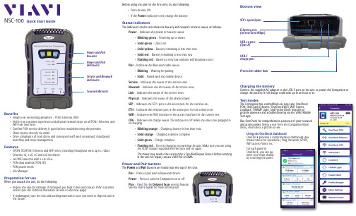
Before using the unit for the first time, do the following:y Turn the unit ON.y If the Power indicator is red, charge the battery.Status indicatorsThe indicators on the unit show the battery and network connect status, as follows:Power – Indicates the power or battery statusy Blinking green – Powering up or down y Solid green – Unit is ony Solid yellow – Battery remaining is less than 30%y Solid red – Battery remaining is less than 10%y Flashing red – Battery is very low and unit will shutdown soon Pair – Indicates the Bluetooth radio statusy Blinking – Waiting for pairingy Solid – Paired with the mobile device Service – Indicates the status of the service tests Network – Indicates the the status of the service testsLink – Indicates the status of the service tests Physical – Indicates the status of the physical layerSFP – Indicates the SFP+ port is the active port for the current test ETH – Indicates the ethernet port is the active port for the current testWiFi – Indicates the WiFi interface is the active interface for the current testCHG – Indicates the charge status. The indicator is off when the unit is not plugged in or charging.y Blinking orange – Charging, battery is less than 90% y Solid orange – Charging is almost complete y Solid green – Charge completey Flashing red – Error in charging or powering the unit. Make sure you are using the VIAVI charger supplied with the unit and try again.The meter may need to be serviced by a Certified Repair Center. Before sending in the unit for repair, contact VIAVI for an RMA.Power and Pair buttonsThe Power and Pair buttons are found near the top of the unit.Pair – Press to pair with a Bluetooth device Power – Press to turn the Companion on or off Play – Used for the Delayed Start testing feature. See the User’s Guide for more information.NSC-100Quick Start GuideBenefitsy Simply test everything anywhere – PON, Ethernet, WiFiy Verify true customer experience and physical network layer on all PON1, Ethernet, and WiFi test interfaces y Confirm PON service delivery is good before troubleshooting the premises y Share reports directly via emaily Drive compliance of both direct and contracted staff with centralized, cloudbased workflow and result managementFeaturesy GPON, XGSPON, Ethernet and WiFi tests, including throughput tests up to 2 Gbps y Ethernet 1G, 2.5G, 5G and 10G interfaces y 3x3 WiFi antenna with 2.4 & 5GHz y PON data analysis (PON-ID) y PON power levels y Job ManagerPreparation for useWhen you unpack the unit, do the following:y Inspect the unit for damage. If damaged, put back in box and contact VIAVI customer service (see the Technical Assistance section on the next page). y If undamaged, save the box and packing materials in case you need to ship the unit in the future.Power and Pair indicatorsService and Network indicatorsPower and Pair buttons Status indicatorsBottom viewEthernet port(10/100/1000 Mbps)USB-Ccharge portUSB 3.0 port (Type A)SFP+ optical port Protective rubber doorCharging the batteryConnect the supplied AC adapter to the USB-C port on the unit to power the Companion or charge the battery. A full charge could take up to an hour or so.Test modesThe Companion has a simplified test structure: OneCheck PON, OneCheck Ethernet, OneCheck WiFi, WiFi Expert, Loopback, TWAMP Light, and Fusion Client features toprovide autotests and troubleshooting via the VIAVI Mobile Tech app.Run OneCheck for comprehensive autotests of your network and access points. S elect a test from the Companion Main menu, then select a profile to test.Using the OneCheck dashboardOneCheck provides a comprehensive dashboard that shows results for Speedtests, Ping, Network, GPON, WiFi access Points, etc.For each panel inOneCheck, you can get more test result details by touching the panel.Pairing the Companion to your mobile deviceTo control the user interface of the Companion, the mobile device must be paired with the unit over Bluetooth.1.On the Companion, press and hold the Pairbutton for 3 seconds to enter pairing mode. The blue Pair indicator blinks.2.On the mobile device, do the following:y Go to the Settings menu, then select Bluetooth .y Verify that the device is not paired with any NSC-100 Companion unit.3.From the Mobile Tech Main menu, under My Devices , find the Companion, shown as “NSC-100”, and select Connect .If you don’t see the device, you may need to select Discover Devices .4. When the Companion is connected, the Pair indicator will be solid.5.On the mobile device, the Companion should be paired and the Main menu will now show the Companion menu.You can now control the instrument through the Mobile Tech app and run all tests on the Companion.© 2021 VIAVI Solutions Inc.Product specifications and descriptions in this document are subject to change without notice.22137285 July 2021EnglishVIAVI SolutionsNorth America 1.844.GO VIAVI / 1.844.468.4284Latin America +52 55 5543 6644EMEA +49 7121 862273APAC+1 512 201 6534All Other Regions/contacts***************************Mobile Tech Main menuIn the Main menu, you can see details of the instrument, run Companion tests, sync to StrataSync, manage files on the unit, and even view documentation.You’ll also see the date and time of the last time your meter synced to StrataSync.Near the top of the Main menu, you can select Show more to see details on your instrument, including all of the installed options.Using the Companion with a mobile deviceThe Companion is designed to be paired with a mobile device or tablet(such as an iPhone, iPad, or similar Android device), and leverages the user interface of those devices along with the VIAVI Mobile Tech app to provide a smooth user experience.You can view test results, set up the Companion, sync files, update the meter, and configure test parameters from the app.To get started, download the VIAVI Mobile Tech app from the App Store or Google Play.Connecting to StrataSyncYou can connect to StrataSync using your smartphone or tablet anytime, anywhere using the VIAVI Mobile Tech app.Once your instrument is connected to the Mobile Tech app via Bluetooth, geo locationinformation can be added to reports and files when syncing to StrataSync. If configuration files or work orders are set to be deployed from StrataSync to your meter, you can check those here, as well as browsing files from the unit itself.Once you download the application, log in to StrataSync just as you do on the website. To operate the tests, follow the instructions on the application screens.Mobile T echUsing the Mobile Tech appLogging in to StrataSyncTo get started using the Mobile Tech app, you need to log in to StrataSync.1. Launch the Mobile Tech app on your mobile device.2. Select the Login to StrataSync button. The Login screen will be displayed.3.Enter your Username and Password, then select the Sign In button. The Mobile Tech Main menu will be displayed.y – Run tests and configure profiles for the CompanionBefore doing any tests, you may need to set up profiles for your network. Companion > Profile y Job Manager – Attach jobs to tests, including customer info and work orders, and track test results y Instrument Sync – Sync your instrument to StrataSync and deploy configuration filesy NSC-100 Files and Mobile Tech Files – Manage the files on the unit you can save to your phone or tablet. Use the NSC-100 Files menu to manage filesstored on your meter, use the Mobile Tech Files menu to manage those stored on your mobile device. y Documentation – View and download various documentation for your instrument, including applications notes, software release notes, and quick reference guidesTechnical assistanceIf you require technical assistance, call 1-844-GO-VIAVI / 1.844.468.4284.For the latest TAC information, visit/en/services-and-support/support/technical-assistanceConnect buttonNSC-100。
PicoLog 1000系列PC数据记录器用户指南说明书

Copyright © 2013 Pico Technology Ltd. All rights er's Guidepl1000.en r2PicoLog 1000 SeriesI PicoLog 1000 Series User's GuideContents1 Introduction (1) (1)1 Overview (2)2 Safety warning (3)3 Leg al information (4)4 Accessories (4)5 Company details (5)6 Connecting the log g er (5)7 Getting started (6)8 Example circuit (voltag e) (7)9 Example circuit (lig ht)2 Product information (8) (8)1 Specifications (9)2 I/O connector pins (10)3 USB ADC-11 compatibility mode (11)3 Glossary (13)IndexPicoLog 1000 Series User's Guide1 1Introduction1.1OverviewThe PicoLog 1000 Series PC Data Loggers are m edium-speed, m ultichannel voltage-input devices for sam plinganalog data using a PC. This m anual describes the physicalproperties of the loggers.The following PicoLog 1000 Series Data Loggers are available:Version Resolution ChannelsPicoLog 101210 bits12PicoLog 121612 bits16These devices are designed for use with the PicoLog data logging software and thePicoScope oscilloscope software. You can also use the PicoLog API supplied todevelop your own program s to collect and analyse data. See the PicoLog 1000 SeriesProgram m er's Guide for details of the API.Introduction 21.2Safety warningWe strongly recom m end that you read the general safety inform ation below beforeusing your product for the first tim e. If the equipm ent is not used in the m annerspecified, then the protection provided m ay be im paired. This could result in dam ageto your com puter and injury to yourself or others.Maximum input rangeThe inputs of the PicoLog 1000 Series loggers are protected against overvoltages up to ±30 V. Input voltages beyond this range m ay cause perm anent dam age to the unit.Mains voltagesPico products are not designed for use with m ains voltages. To m easure m ains werecom m end the use of a differential isolating probe specifically designed for suchm easurem ents.Safety groundingThe ground of every unit is connected directly to the ground of your com puter via theinterconnecting cable provided. This is done to m inim ise interference. If the PC(especially laptops) is not grounded, reading stability cannot be guaranteed and it m ay be necessary to m anually ground the equipm ent.As with m ost oscilloscopes and data loggers, you should take care to avoid connecting the inputs of the unit to any equipm ent which m ay be at an unsuitable voltage. If indoubt, use a voltm eter to check that there is no hazardous AC or DC voltage. Failureto check m ay cause dam age to the product and/or com puter and could cause injury to yourself or others.You should assum e that the product does not have a protective safety earth.Incorrect configuration and/or use on voltages outside the m axim um input range can be hazardous.CleaningThe unit m ay be cleaned externally using a cloth dam pened slightly with water. Do not use any other solvents or abrasive cleaning m aterials.RepairsThe unit contains no user-serviceable parts. Repair or calibration of the unit requiresspecialised test equipm ent and m ay be perform ed only by Pico Technology or itsauthorised distributors.PicoLog 1000 Series User's Guide31.3Legal informationThe m aterial contained in this release is licensed, not sold. Pico Technology grants alicence to the person who installs this software, subject to the conditions listed below.AccessThe licensee agrees to allow access to this software only to persons who have beeninform ed of these conditions and agree to abide by them.UsageThe software in this release is for use only with Pico products or with data collectedusing Pico products.CopyrightPico Technology claim s the copyright of, and retains the rights to, all m aterial(software, docum ents etc.) contained in this release. You m ay copy and distribute theentire release in its original state, but m ust not copy individual item s within the release other than for backup purposes.LiabilityPico Technology and its agents shall not be liable for any loss, dam age or injury,howsoever caused, related to the use of Pico Technology equipm ent or software,unless excluded by statute.Fitness for purposeNo two applications are the sam e: Pico Technology cannot guarantee that itsequipm ent or software is suitable for a given application. It is your responsibility,therefore, to ensure that the product is suitable for your application.Mission-critical applicationsThis software is intended for use on a com puter that m ay be running other softwareproducts. For this reason, one of the conditions of the licence is that it excludes usage in m ission-critical applications, for exam ple life support system s.VirusesThis software was continuously m onitored for viruses during production, but you areresponsible for virus-checking the software once it is installed.SupportIf you are dissatisfied with the perform ance of this software, please contact ourtechnical support staff, who will try to fix the problem within a reasonable tim e scale. If you are still dissatisfied, please return the product and software to your supplier within28 days of purchase for a full refund.UpgradesWe provide upgrades, free of charge, from our web site. We reserve the right tocharge for updates or replacem ents sent out on physical m edia.TrademarksPico Technology, PicoScope and PicoLog are tradem arks of Pico Technology Ltd.,registered in the United Kingdom and other countries. Pico Technology acknowledgesthe following product nam es as tradem arks of their respective owners: Windows, Excel, Visual Basic, LabVIEW, Delphi.Introduction 41.4AccessoriesThe following item s are supplied in all packages:Standard items Part no.PicoLog 1000 Series PC Data Logger PP543 (PicoLog 1012)PP544 (PicoLog 1216)USB cable MI106Software and Reference CD-ROM DI025USB Installation Guide DO112The following additional item s are supplied in som e packages (see our website fordetails):Additional items Part no.Sm all Term inal Board PP545Sm all Term inal Board User's Guide DO161The Sm all Term inal Board m akes connecting wires to the Data Logger m uch easier.Instead of soldering wires to a 25-way D-type plug, you can sim ply insert preparedwire ends into the screw term inals on the term inal board. The board also containssolder pads to allow you to fit resistors that divide the input voltage to each channelby a known ratio, thereby expanding the m easuring range by the sam e ratio. Forexam ple, if you divide the input voltage by 4, then the effective input range of theData Logger is increased from 2.5 V to 10 V on that channel.1.5Company detailsAddress: Pico TechnologyJam es HouseColm worth Business ParkST. NEOTSCam bridgeshirePE19 8YPUnited KingdomPhone:+44 (0) 1480 396 395Fax: +44 (0) 1480 396 296Email:Technical Support********************Sales******************Web site:PicoLog 1000 Series User's Guide 51.6Connecting the loggerBefore you connect your logger, you must install the software supplied on theCD.To connect the PicoLog logger, plug the cable provided into any available USB port onyour PC.I/O connector: for the pin-num bering of the I/O connector, see I/O connector pins. The Pico PP545 Sm all Term inal Board is specially designed to connect to this socketto allow you to m ake connections to individual wires easily without soldering. If youneed to use a ribbon cable to connect your signals to this socket, use the shortestpossible length to avoid introducing too m uch crosstalk between the signals.Status LED: this flashes while the device is capturing data. The flash rate depends on the sam pling rate.USB port: use the USB cable supplied to connect this to the PC that is running the Pico software. A PC with a USB 2.0 port is recom m ended for best performance.1.7Getting startedTo check that the unit is working, start the PicoScope program by clicking thePicoScope icon on your desktop:You should im m ediately see a signal trace on the screen. As the inputs are high-im pedance, the trace will show noise until a defined voltage is applied to the input. If you connect a 1.5 V battery between the GND term inal and the C1 analog input (see I/O connector pins ), you should see the signal jum p to +1.5 V. Alternatively you cangenerate a test voltage using a potential divider connected between the PO outputand a GND term inal.996Introduction 1.8Example circuit (voltage)This is how to connect a sim ple voltage source to the Data Logger:The com ponents of the circuit are as follows:Once you have built the circuit, connect it to the Data Logger, run the PicoScope 6software and watch the trace on the display. When the voltage source is connected,the trace should rise to the level of the source voltage. When the voltage source isdisconnected, the trace should fall to zero volts.PicoLog 1000 Series User's Guide71.9Example circuit (light)Here is an exam ple of a sensor circuit that you could connect to the logger.The com ponents of the circuit are as follows:Once you have built the circuit, connect it to the Data Logger, run the PicoScope 6software and watch the trace on the display. When the sensor is exposed to light, the trace should rise to alm ost 2.5 V. When the sensor is covered, the trace should fall toa value close to 0 V.Product information 82Product information2.1SpecificationsNotes:1.Block m ode is supported by PicoScope and the PicoLog 1000 Series API, but not byPicoLog.2.Except in USB ADC-11 com patibility m ode (see I/O connections table)109PicoLog 1000 Series User's Guide 92.2I/O connector pins The I/O connector is the 25-way connector on the front of the unit. Pin num bers andsignal nam es are as follows. See Specifications for further details of input andoutput characteristics.Note 1:These outputs are available when the unit is used in USB ADC-11com patibility m ode .Note 2:The ground pins are protected by resettable fuses. If you connect one of the ground pins to a voltage source such as a power pack, and the voltage source shares a ground connection with the USB cable to the Data Logger,then a large current will flow into the ground pin. The fuse will detect this condition and disconnect the pin before dam age is caused to the Data Logger. The fuse will autom atically reset itself when the voltage source is disconnected from the input pin.Note 3:NC = not connected810Product information 10The I/O connector pins are numbered as follows:2.3USB ADC-11 compatibility modeThe PicoLog 1000 Series data loggers m ay be used as replacem ents for the USB ADC-11, an 11-channel data logger previously available from Pico Technology. The 1000Series units have all the functions of the USB ADC-11 and som e extra functions, suchas extra digital outputs , a PWM output and a sensor power output. They alsohave a faster USB interface and m ore advanced driver software.If you use a 1000 Series unit with old versions of PicoScope and PicoLog that werereleased before April 2009, then it will autom atically em ulate a USB ADC-11. You cancontinue to use the unit as an USB ADC-11 if you wish, or you can upgrade yoursoftware to enable the extra functions of the new unit.99PicoLog 1000 Series User's Guide11 3GlossaryAccuracy. The closeness between m easured values and true values. This is m oreusually expressed as the error, as a percentage of full scale, between the m easuredvalue and the true value.ADC. Analog to Digital Converter. An ADC sam ples analog signals and converts themto digital data for storage and processing. It is an essential com ponent of a datalogger.Analog bandwidth. The range of input frequencies over which the m easured signalpower is at least half its true value. This corresponds to a drop in am plitude of about29%.Duty cycle. For a square wave signal, the proportion of the tim e that the signalspends at the high level divided by the period of the signal, expressed as a percentage.Thus, a sym m etrical square wave has a duty cycle of 50%.Input impedance. The im pedance of the input channels of the logger with the inputdisconnected. Im pedance is the total opposition (due to resistance, capacitance andinductance) offered to the flow of an alternating current.Linearity. The ideal output of an ADC is a linear function of its analog input. Linearity is a m easure of the worst-case deviation from this ideal characteristic.Maximum sampling rate. A figure indicating the m axim um num ber of sam ples theADC is capable of acquiring per second. Maxim um sam ple rates are usually given in S/s(sam ples per second.) The higher the sam pling rate of the ADC, the m ore accurately it can represent the high-frequency details in a signal.Overload protection. The m axim um voltage that can be applied across the inputs ofthe ADC without causing dam age to it.PWM. Pulse-width m odulation. A way of conveying analog inform ation by m eans of asingle binary signal. The PWM output from the PicoLog 1000 Series units is a squarewave between 0 volts and +3.3 volts, with variable duty cycle. The average voltageof the signal is the peak voltage, 3.3 volts, m ultiplied by the duty cycle. The signalcan be used to control proportionalResolution. A value, in bits, indicating the num ber of distinct input levels that theADC can turn into digital values.11USB. Universal Serial Bus. This is a standard port that enables you to connectexternal devices to PCs. A typical USB 1.1 port supports a data transfer rate of 12m egabits per second and is m uch faster than an RS-232 serial port. A full-speed USB2.0 port operates at up to 480 m egabits per second.PicoLog 1000 Series User's Guide13IndexAAccessories 4Accuracy 8, 11ADC 11ADC-11 compatibility mode 8, 10 Analog bandwidth 11Analog inputs 8BBandwidth 8Block mode 8CCircuit example 6, 7Compliance 8Connections 5Contact details 4DDigital outputs 8Dimensions 8Duty cycle 11EEnvironmental conditions 8 Example circuit 6, 7II/O connector 5, 8Input coupling 8Input impedance 8, 11Input rangeexpanding 4LLDR 7LED 5Legal information 3Linearity 8, 11MMaximum sampling rate 11OOverload protection 8, 11 Overview 1PPC connection 8PicoScope 5Power output 8PWM 11PWM output 8RResolution 8, 11SSafety warning 2Sampling rate 8Small Terminal Board 4 Specifications 8Status LED 5Streaming mode 8TTerminal board 4UUSB 11USB ADC-11 compatibility mode 10 USB port 5, 8VVoltage input connection 6WWeight 8PicoLog 1000 Series User's Guide15Pico TechnologyJames HouseColmworth Business ParkST. NEOTSCambridg eshire PE19 8YPUnited King domTel: +44 (0) 1480 396 395Fax: +44 (0) 1480 396 296Copyright © 2013 Pico Technology Ltd. All rights reserved.pl1000.en r2 10.05.2013。
TP1000中文资料

Rev1.1
南京拓品微电子有限公司 NanJing Top Power ASIC Corp.
典型特性曲线(TA=25℃,Vout=5V,TP1000D
5.03 5.02 5.01
恒流(mA)
恒压(V)
为例,有特别说明除外。 )
535 530 525 220Vac
5.00 4.99 4.98 4.97 4.96 -50 -25 0 25 50 75
+
Delay
Drv
器件标记 00Dm(m 为生产标识,可变)
(D 可变,详细见订单描述)
1 2 3
引脚号 1 2 3 4 5
5 4
功能 芯片工作电源输入端 接地端 辅助绕组电压采样端 初级线圈电流采样端 三极管基极驱动端
订单描述
芯片打字 00Am 00Dm 00Gm 线缆补偿 参数 Vout=5V 为例 0mV 150mV 300mV 封装 SOT23-5L SOT23-5L SOT23-5L 包装 REEL REEL REEL
南京拓品微电子有限公司 NanJing Top Power ASIC Corp.
南京拓品微电子有限公司
DATASHEET
(TP1000 高精度恒压/恒流原边反馈控 制器)
Rev1.1
南京拓品微电子有限公司 NanJing Top Power ASIC Corp.
高精度恒压/恒流原边反馈控制器—TP1000 系列
(7)
即
VO V FB
(8)
式(8)中 V FB 为 FB 端采样比较点,VFB 1.2V 。在设计中, N AUX 、 N S 、Vd 、 R3 和 R4 确定的情 况下,即可得出恒压输出 VO 的值。
TP700多路温度记录仪说使用明书

� � � �
基本误差小于±0.2%F·S,数字显示范围-999.99~1999.99 测量分辨力:1/60000,24 位 AD 转换器 实时曲线记录间隔 1 秒~9999 秒,对应整屏曲线时间 30 秒~300 分 追忆曲线记录间隔从 1 秒到 9999 秒连续可设
3.2 输入信号
输入信号包括直流电流,直流电压,热电阻,热电偶,远传压力表五类, 通 过按键输入选择。隔离万能输入,无需跳线器。 直流电流: (4~20)mA, (0~10)mA, (0~20)mA; 直流电压: (0~5)V ,(0~10)V,-20~+20mA ; 热电阻:Pt100,Cu50; 热电偶:K,S,R,B,N,E,J,T ; 其它输入信号或分度号需在订货时注明。
5.3 开机画面
屏幕会显示点击屏幕进入启动属性窗口,这时我们不需要去点击屏幕,让屏 幕直接进入显示开机启动画面。
5.4 显示界面
11
TP700 多路温度记录仪 显示界面可以对当前的状况有比较全面的了解,包括测量名称,测量值,工 程量单位,报警指示,报警输出状态等。画面的形式如下:
5.5(数显)数字显示界面
2
TP700 多路温度记录仪
二、 功能特点
本产品显示信息量大、界面友好、操作简单,下面是主要功能特点:
� 不需要笔和纸记录,日常维护工作量非常小,运行费用低; � 采用高亮度触控彩色 TFT 液晶屏,CCFL 背光、画面清晰; � 采用 ARM 微处理器,可同时实现多路(仪器内部最高 64 路信号采集、
TP700 多路温度记录仪说明书
目
一、 二、 三、 四、 五、 六、 七、 八、
录
概述...................................................................................................... 1 功能特点 ............................................................................................. 2 技术指标 ............................................................................................. 4 安装与接线及外形结构 ....................................................................6 仪表运行及操作.................................................................................9 仪表参数设置及通讯协议..............................................................20 软件使用说明 ...................................................................................27 故障分析与排除...............................................................................30
SMPT-1000使用说明
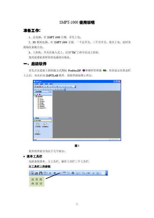
SMPT-1000使用说明准备工作:1、总电源:在SMPT-1000左侧,首先上电;2、IO模块电源:在SMPT-1000正面,一个总开关,三个分开关,依次上电,此时各现场仪表被点亮;3、工控机:开关在嵌入式上,打到“On”上即可启动工控机。
使用前要检查所有的电源供应情况。
一、启动软件首先点击桌面上的快捷方式图标ProfibusDP 和硬件管理器,待其显示在状态栏上之后,双击启动SMPTLAB软件。
初始界面如图1所示。
图1软件的界面分为以下几个部分:♦菜单工具栏包括系统菜单、主工具栏、操作工具栏三个工具栏。
主工具栏上的按钮流程图画面切新建按钮:新建实验工程。
打开按钮:打开已存在的实验工程。
保存按钮:保存正在运行的实验工程,同时保存当前的工况。
另存为按钮:将当前时刻的工况在新的工程目录中保持,即存为快门。
运行按钮:启动当前的实验工程,或从暂停重新恢复运行。
停止按钮:中止实验,流程盘台上设备失活,允许包括流程图与控制组态在内的所有窗口的修改。
数据点定义画面切换按钮:显示/激活/切换到数据点定义画面。
流程图画面切换按钮:显示/激活/切换到流程图画面。
控制组态画面切换按钮:显示/激活/切换到控制组态画面。
报警组画面切换按钮:显示/激活/切换到报警组画面。
新建趋势曲线按钮:新建趋势曲线图。
清零按钮:将系统运行时间回复到T0时刻,同时清除趋势曲线中所有的历史曲线,以重新开始记录。
冷态工况切换按钮:将当前实验项目工况恢复到冷态,即所有设备及工况处于初始状态,但系统运行时间与趋势曲线不变。
该功能为用户在实验失败时,快速恢复到原始状态而设置。
按钮:显示阀门/挡板控制配置对话框。
按钮:4~20mA输入输出数据点设置。
信号线按钮:连接控制组态时所使用的模块,构成控制系统信号传输路径。
撤销按钮:将刚刚进行的对组件的操作撤销。
撤销的步数系统缺省为二十步。
重复按钮:在撤销过程中,按下该按钮可以重新进行刚被撤销的操作。
放大按钮:将当前页面放大25%。
OM-CP-PRTEMP1000 坚固压力和温度数据记录器用户指南说明书

OM-CP-PRTEMP1000Rugged Pressure andTemperature Data LoggerUser’s GuideOM-CP-PRTEMP1000Product NotesGetting StartedTo access the COM Port for the interface cable, unscrew the key-ring end cap.Pressure SensorTo use the pressure sensor for gauge measurements, screw the ¼” male NPT fitting into the pipe to be measured with a 9/16” wrench. The NPT fitting can be used for absolute and submersible applications, but in those cases it’s preferable to use the submersible fitting.SubmergibilityThe OM-CP-PRTEMP1000 is fully submergible and is rated IP68. It can be placed in environments with up to 230 feet (70 m) of water.O-RingsO-ring maintenance is a key factor when properly caring for the OM-CP-PRTEMP1000. The o-rings ensure a tight seal and prevent liquid from entering the inside of the device.Installation GuideInstalling the Interface cable- OM-CP-IFC200Insert the device into a USB port. The drivers will install automatically.-OM-CP-IFC110Plug the serial cable into the port and verify it is secure.Installing the softwareInsert the Omega Software Flash Drive in an open USB port. If the autorun does not appear, locate the drive on the computer and double click on Autorun.exe. Follow the instructions provided in the Installation Wizard.Device OperationConnecting and Starting the data logger1. Once the software is installed and running, plug the interface cable into the data logger.2. Connect the USB end of the interface cable into an open USB port on the computer.3. The device will appear in the Connected Devices list, highlight the desired data logger.4. For most applications, select “Custom Start” from the menu bar and choose the desired start method,reading rate and other parameters appropriate for the data logging application and click “Start”. (“Quick Start” applies the most recent custom start options, “Batch Start” is used for managing multiple loggers at once, “Real Time Start” stores the dataset as it records while connected to the logger.)5. The status of the device will change to “Running”, “Waiting to Start” or “Waiting to Manual Start”,depending upon your start method.6. Disconnect the data logger from the interface cable and place it in the environment to measure.Note: The device will stop recording data when the end of memory is reached or the device is stopped. At this point the device cannot be restarted until it has been re-armed by the computer.2Quick Start ManualDownloading data from a data logger1. Highlight the data logger in the Connected Devices list. Click “Stop” on the menu bar.2. Once the data logger is stopped, with the logger highlighted, click “Download”. You will be prompted toname your report.3. Downloading will offload and save all the recorded data to the PC.Product MaintenanceBattery ReplacementMaterials:Small Needle Nose PliersReplacement Battery (OM-CP-BAT112)1. Carefully unscrew the sensor end cap and pull the electronics out.2. The battery is the purple cylinder on the cirucit board.3. Gently pull out the old battery.4. Insert the new battery one lead at a time, using pliers to fully push the leads into the sockets. The batteryshould be flat against the circuit board, and the positive lead should be closets to the communications jack.5. Ensure the circuit board is inserted into the white plastic bushing. The sensor cable should not be twisted,or kinked. From the connection to the circuit, it should run up towards the battery, then down to the sensor.6. Insert the electronics back into the tube and carefully screw the cap on.RecalibrationThe OM-CP-PRTEMP1000 standard temperature calibration is one point at 25 °C. The pressure calibration isdepend on the range.Recalibration is recommended annually for any Omega data logger; a reminder is automatically displayed in the software when the device is due.3OM-CP-PRTEMP1000OM-CP-PRTEMP1000 General SpecificationsBattery WarningWARNING: FIRE, EXPLOSION, AND SEVERE BURN HAZARD. DO NOT SHORT CIRCUIT, CHARGE, FORCE OVER DISCHARGE, CRUSH, PENETRATE OR INCINERATE. BATTERY MAY LEAK OR EXPLODE IF HEATED ABOVE 150°C (302°F).Specifications subject to change.See Omega’s terms and conditions at 4WARRANTY/DISCLAIMEROMEGA ENGINEERING, INC. warrants this unit to be free of defects in materials and workmanship for a period of 61 months from date of purchase. OMEGA’s WARRANTY adds an additional one (1) month grace period to the normal five (5) year product warranty to cover handling and shipping time. This ensures that OMEGA’s customers receive maximum coverage on each product.If the unit malfunctions, it must be returned to the factory for evaluation. OMEGA’s Customer Service Department will issue an Authorized Return (AR) number immediately upon phone or written request. Upon examination by OMEGA, if the unit is found to be defective, it will be repaired or replaced at no charge. OMEGA’s WARRANTY does not apply to defects resulting from any action of the purchaser, including but not limited to mishandling, improper interfacing, operation outside of design limits, improper repair, or unauthorized modification. This WARRANTY is VOID if the unit shows evidence of having been tampered with or shows evidence of having been damaged as a result of excessive corrosion; or current, heat, moisture or vibration; improper specifica-tion; misapplication; misuse or other operating conditions outside of OMEGA’s control. Components in which wear is not war-ranted, include but are not limited to contact points, fuses, and triacs.OMEGA is pleased to offer suggestions on the use of its various products. However, OMEGA neither assumes respon-sibility for any omissions or errors nor assumes liability for any damages that result from the use of its products in accordance with information provided by OMEGA, either verbal or written. OMEGA warrants only that the parts manufactured by the company will be as specified and free of defects. OMEGA MAKES NO OTHER WARRANTIES OR REPRESENTATIONS OF ANY KIND WHATSOEV ER, EXPRESSED OR IMPLIED, EXCEPT THAT OF TITLE, AND ALL IMPLIED WARRANTIES INCLUDING ANY WARRANTY OF MERCHANTABILITY AND FITNESS FOR A PARTICULAR PURPOSE ARE HEREBY DISCLAIMED. LIMITATION OF LIABILITY: The remedies of purchaser set forth herein are exclusive, and the total liability of OMEGA with respect to this order, whether based on contract, warranty, negli-gence, indemnification, strict liability or otherwise, shall not exceed the purchase price of the component upon which liability is based. In no event shall OMEGA be liable for consequential, incidental or special damages.CONDITIONS: Equipment sold by OMEGA is not intended to be used, nor shall it be used: (1) as a “Basic Component” under 10 CFR 21 (NRC), used in or with any nuclear installation or activity; or (2) in medical applications or used on humans. Should any Product(s) be used in or with any nuclear installation or activity, medical application, used on humans, or misused in any way, OMEGA assumes no responsibility as set forth in our basic WARRANTY / DISCLAIMER language, and, additionally, purchaser will indemnify OMEGA and hold OMEGA harmless from any liability or damage whatsoever arising out of the use of the Product(s) insuch a manner.FOR WARRANTY RETURNS, please have the following infor-mation available BEFORE contacting OMEGA:1. P urchase Order number under which the product was PURCHASED,2. M odel and serial number of the product under warranty, and 3. R epair instructions and/or specific problems relative to the product.FOR NON-WARRANTY REPAIRS, consult OMEGA for current repair charges. Have the following information available BEFORE contacting OMEGA:1. Purchase Order number to cover the COST of the repair,2. Model and serial number of the product, and3. R epair instructions and/or specific problems relative to the product.OMEGA’s policy is to make running changes, not model changes, whenever an improvement is possible. T his affords our customers the latest in technology and engineering. OMEGA is a registered trademark of OMEGA ENGINEERING, INC.© Copyright 2014 OMEGA ENGINEERING, INC. All rights reserved. This document may not be copied, photocopied, reproduced, translated, or reduced to any electronic medium or machine-readable form, in whole or in part, without the prior written consent of OMEGA ENGINEERING, INC.RETURN REQUESTS / INQUIRIESDirect all warranty and repair requests/inquiries to the OMEGA Customer Service Department. BEFORE RET URNING ANY PRODUCT (S) T O OMEGA, PURCHASER MUST OBT AIN AN AUT HORIZED RET URN (AR) NUMBER FROM OMEGA’S CUST OMER SERVICE DEPARTMENT (IN ORDER TO AVOID PROCESSING DELAYS). The assigned AR number should then be marked on the outside of the return package and on any correspondence.The purchaser is responsible for shipping charges, freight, insurance and proper packaging to prevent breakage in transit.Servicing North America:U.S.A.:Omega Engineering, Inc., One Omega Drive, P.O. Box 4047S tamford, CT 06907-0047 USA Toll-Free: 1-800-826-6342 (USA & Canada only)Customer Service: 1-800-622-2378 (USA & Canada only) Engineering Service: 1-800-872-9436 (USA & Canada only) Tel: (203) 359-1660 Fax: (203) 359-7700 e-mail:**************For Other Locations Visit /worldwide***********************The information contained in this document is believed to be correct, but OMEGA accepts no liability for any errors it contains, and reserves the right to alter specifications without notice.WARNING: These products are not designed for use in, and should not be used for, human applications.MQS5103/10/15。
TP1000数据记录仪说明书

� 配备标准 USB2.0 接口。可使用鼠标键盘方便操作,输入历史数据转
存快捷方便,
2
TP1000 记录仪·使用手册
� 标准串行通讯接口, 带光偶隔离的 RS485 和 RS232C 以及以太网; � 支持标准 ModBus RTU 通讯协议(选配功能) ,除支持本公司数据
电流输出(4~20) mA, (0~10) mA, (0~20) mA 可选。 电压输出 (0~24) V, 其他电压可选。 出厂默认设定为(0~24 )V, 其他类型订货时注明。
1
TP1000 记录仪·使用手册
二、 功能特点
本产品显示信息量大、界面友好、操作简单,下面是主要功能特点:
� 不需要笔和纸记录,日常维护工作量非常小,运行费用低; � 采用高亮度触控彩色 TFT 液晶屏,CCFL 背光、画面清晰; � 采用 ARM 微处理器, 可同时实现多路(1001 型为仪器内部最高 64 路,
3.3 报警输出及变送输出 � 继电器输出:触点容量 AC 220V,3A,阻性负载 � 12 点可参数设置输出,可按通道的各报警点值设定 � 可参数设置 8 点变送输出,光电隔离,误差小于± 0.2% F ·S ,电流输
出负载能力≤450Ω 电压输出配接设备阻抗:需大于 2KΩ
3.4 外供电源 � DC 24V 电源:用于给变送器供电,最大负载能力≤200mA
5.3 开机画面 屏幕会显示点击屏幕进入启动属性窗口,这时我们不需要去点击屏 幕,让屏幕直接进入显示
5.4 总貌画面
总貌画面可以对当前的状况有比较全面的了解,包括测量名称,测量值, 工程量单位,输入信号类型,报警指示,报警输出状态等。画面的形式如下:
9
TP1000 记录仪·使用手册
徕卡TPS1000使用说明

徕卡 TPS1000 系列全站仪
的坐标来进行测站设置,仪器自动反算方位角,自动进行设置。 13、常规测量 操作: 按 F6(MEAS)键进入常规测量状态 如果要求测量坐标,你必须先进行测站设置,才能进行常规测量;而如果你只需要测量 距离和角度,而不计算坐标,你可以不进行测站设置而直接进入常规测量。 四、按 进入照明及加热选择界面
识别
锁定
1. User template & files 选择用户模板和文件
aF…\ USER TEMPLATE—FILES Select user template & files User templ. :USER4 Rec. device :1 Meas. file Data file :1 :1 Memory Card FILE01.GSI FILE01.GSI / 2 RS232 user templ.: 用户模板选择, 有 Polar(standard)极坐标。 Cartesian 笛卡尔坐标。Polar+Cartesian 极坐标+笛卡 尔坐标。USER4/USER5 用户自定义 4/5 rec.device:记录装置选择 memory card(PC 卡)和 RS232 接口 meas.file :选择测量文件名,12 个可供选择。 data file :选择数据文件名
ATR
LOCK
L.INT
识别
锁定
中止
F1(ATR) 打开或关闭 ATR 自动目标识别功能。 F2(LOCK) 锁定目标棱镜,用于跟踪测量。
第-4-页
徕卡 TPS1000 系列全站仪
2. EDM measuring program 距离测量方式设置(标准/精测/快速/跟踪/平均数)
OM-CP-LEVEL1000 水位和温度数据记录仪说明书

OM-CP-IFC200
119 Windows software and 3.7 m (12') USB interface cable
OM-CP-BAT102
10 Replacement 3.6 V lithium battery
Data logger is supplied with 30' long electrical interface cable/atmospheric pressure compensation tubing assembly. Contact Omega for other lengths. Operator's manual and RS-232 cable are included with the OM-CP-IFC110 Windows software (software is required to operate the data logger and is sold separately). NIST calibration for temperature only.
Computer Interface: PC serial or USB (interface cable required); 2400 baud Software: WIN98/NT/2000/XP/VISTA 32-bit (VISTA 32-bit version only; VISTA 64-bit is not supported) Operating Environment: -40 to 80°C (-40 to 176°F),
0 to 100% RH
AVAILABLE FOR FAST DELIVERY!
To Order (Specify Model Number)
记录仪STR1000的使用SOP汇总

登记号:1. 目的:建立记录仪STR1000 的使用标准操作规程。
2. 范围:本规程适用于注射用水储存及分配系统、纯蒸汽发生器系统。
3. 职责:生产部制水岗位操作人员对本规程的实施负责。
4. 规程:4.1. 记录仪的每个通道均可实现曲线图打印和数字打印,能在本身打印的100mm 宽的纸格上同时记录刻度值、时间及每一个信号的曲线,并将通道号印在各通道的轨迹旁。
通过键盘设定测量的所有参数。
4.2. 输入信号种类及测量范围:4.3.1. 显示方式:4.3.1.1. 在测量状态下,显示通道号和测量值。
4.3.1.2. 在设定状态下,显示设定内容。
4.3.1.3. 在通道全部关闭时,显示实时时间。
4.3.1.4. 六个指示灯为继电器动作号码提示灯4.3.2. 记录方式:4.3.2.1. 打印记录曲线(记录状态,记录指示灯亮)4.3.2.2. 打印设定参数(在记录指示灯灭时,按报表键)4.3.2.3. 打印测量值数据(在记录指示灯亮时,按报表键)4.3.3. 设定状态下,数码管依次显示的内容:1~8 通道号A 量程代码01 35d 小数点位0 3┣显示下限-1 ~9[0 1 2 3 4 5 6 7 8 9 ]┫显示上限[ 记录左边界] 记录右边界H 报警上限L 报警下限H. 偏差上限0000~9999L. 偏差下限E 报警回差00~99误差校正-或+00~99 P走纸速度0000~1990 mm/hb记录标尺0~8U自动打印测量值时间间隔0000~9999 分钟4.4. 键盘操作,该表共有六个使用键,其中有测量状态使用键和设定状态使用键。
4.4.1. 测量状态使用键:记录键:按一次,记录指示灯亮,仪表根据设定的方式打印模拟曲线;再按一次,则记录指示灯灭,仪表不记录。
只显示测量值。
定点键:按一次,将当前显示通道固定;再按一次巡回显示各通道测量值。
走纸键:按一次,仪表快速走纸;再按一次,恢复原状态。
报表键:在记录指示灯灭时,按一次,打印所有设定参数值及当前时间、纸速;在记录指示灯亮时,按一次,打印各通道当前测量值及当前时间、纸速。
OM-CP-TEMP1000IS温度数据记录器说明书

E-1ߜIntrinsically Safe for Class 1, Div 1, Groups ABCD and Non-incendive for Class 1, Div 2, Groups ABCD Indoor/Outdoor (NEMA Type 4X, 6P)LocationsߜSubmersible to 46 m (150')ߜUser Calibration Through SoftwareߜProgrammable Start Time ߜReal Time OperationOM-CP-TEMP1000IS Intrinsically Safe Temperature Data LoggerPart of the NOMAD ®Family$199Basic UnitReal Time Recording: Device may be used with PC to monitor and record data in real time Temperature Calibration:Digital calibration through software Recording Interval: 2 seconds to 12 hours selectable in software Calibration Date: Automatically recorded within device to alert user when calibration is requiredPower: 3.6 V lithium battery included Battery Life: 1 year typical Data Format: Date and time stamped, °C, °F, °K, °RTime Accuracy: ±1 minute per month at 20°C when RS-232 port is not in useComputer Interface: PC serial,RS-232C COM or USB (interface cable required) 2400 baudSoftware:WIN98/NT/2000/XP/VISTA 32-bit (VISTA 32-bit version only; VISTA 64-bit is not supported)Operating Environment:-40 to 80°C (-40 to 176°F),0 to 100% RH non-condensing Dimensions: 108 dia x 26 mm L (4.3 x 1.0")Weight: Aluminum: 110 g (4 oz)Stainless: 230 g (8 oz)software (software is required to operate the datalogger and is sold separately).Ordering Example: OM-CP-TEMP1000IS-CERT Intrinsically safe temperature datalogger with NIST calibration certificate and OM-CP-IFC110Windows software and RS-232 cable, $259 + 99 = $358.OM-CP-TEMP1000IS, $199, shownslightly larger than actual size.The OM-CP-TEMP1000IS is a rugged, waterproof, battery powered, stand-alone device that can automatically recordtemperatures between -40 to 80°C (-40 to 176°F). This all-in-onecompact, portable, easy to use device will measure and record up to32,767 temperature measurements.The OM-CP-TEMP1000IS is ideal for use in harsh environments. Its real time clock ensures that all the data is time and date stamped. The storage medium is non-volatile solid state memory, providing maximum data security even if the battery becomes discharged. The device can be started and stopped directly from your computer and its small size allows it to fit almost anywhere.The OM-CP-TEMP1000IS makes data retrieval quick and easy. The software converts your PC into a real time strip chart recorder. Data can be printed in graphical ortabular format and can be exported to a text or Microsoft fileSpecificationsTemperature Sensor:SemiconductorTemperature Range:-40 to 80°C (-40 to 176°F)Temperature Resolution: 0.1°C Calibrated Accuracy: 0.5°CStart Time: Start time and date are programmable through softwareOM-CP-IFC110, $99, Windows software displays data in graphical or tabular formatCANADA www.omega.ca Laval(Quebec)1-800-TC-OMEGA UNITED KINGDOM Manchester,England0800-488-488GERMANY www.omega.deDeckenpfronn,Germany************FRANCE www.omega.fr 088-466-342BENELUX www.omega.nl 0800-099-33-44UNITED STATES 1-800-TC-OMEGA Stamford,CT.CZECH REPUBLIC www.omegaeng.cz Karviná,Czech Republic596-311-899TemperatureCalibrators, Connectors, General Test and Measurement Instruments, Handheld Instruments for Temperature Measurement, Ice Point References, Indicating Labels,Crayons, Cements and Lacquers, Infrared Temperature Measurement Instruments, Recorders, Relative Humidity Measurement Instruments, PT100 Probes, PT100 Elements,Temperature & Process Meters, Timers and Counters,Temperature and Process Controllers and Power Switching Devices, Thermistor Elements, Probes and Assemblies,Thermocouples, Thermowells and Head and WellAssemblies, Transmitters, Thermocouple Wire, RTD ProbesPressure,Strain and ForceDisplacement Transducers, Dynamic Measurement Force Sensors, Instrumentation for Pressure and StrainMeasurements, Load Cells, Pressure Gauges, PressureReference Section, Pressure Switches, Pressure Transducers,Proximity Transducers, Regulators, Pressure Transmitters,Strain Gauges, Torque Transducers, ValvespH and ConductivityConductivity Instrumentation,Dissolved OxygenInstrumentation,Environmental Instrumentation,pH Electrodes and Instruments,Water and Soil Analysis InstrumentationHeatersBand Heaters,Cartridge Heaters,Circulation Heaters,Comfort Heaters,Controllers,Meters and SwitchingDevices,Flexible Heaters,General Test and Measurement Instruments,Heater Hook-up Wire,Heating Cable Systems,Immersion Heaters,Process Air and Duct,Heaters,Radiant Heaters,Strip Heaters,Tubular HeatersFlow and LevelAir Velocity Indicators,Doppler Flowmeters,LevelMeasurement,Magnetic Flowmeters,Mass Flowmeters,Pitot Tubes,Pumps,Rotameters,Turbine and Paddle Wheel Flowmeters,Ultrasonic Flowmeters,Valves,Variable Area Flowmeters,Vortex Shedding FlowmetersData AcquisitionAuto-Dialers and Alarm Monitoring Systems,Communication Products and Converters,Data Acquisition and Analysis Software,Data LoggersPlug-in Cards,Signal Conditioners,USB,RS232,RS485and Parallel Port Data Acquisition Systems,Wireless Transmitters and Receivers。
TP-1A 简单操作说明书
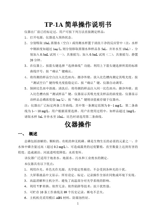
TP-1A简单操作说明书仪器出厂前已经标定过,用户可按下列方法直接测定样品:1、打开电源,仪器进入预热状态。
2、分别吸取10mL蒸馏水(空白)或待测水样置于清洗干净的反应管中(注:水样中铜浓度如超过1mg/L,则分别移取蒸馏水和样品各5mL,并补水至10mL),分别加入0.5mL试剂(一),具塞摇匀,加入0.5mL试剂(二),具塞摇匀。
静置20分钟。
3、在仪器上,按箭头键选择“选择曲线”功能,利用上下箭头键选择所需的标准曲线序号,按“确认”键确认。
4、将待测的样品空白注入比色皿内,擦净外壁,放入比色槽内测定其吸光度,按“测试空白”键待吸光度值稳定后,按“确认”键,仪器自动调零。
5、倒掉比色皿中溶液,清洗后,将待测的样品注入同一比色皿内,擦净外壁,放入比色槽内按“测试样品”键,仪器显示其吸光度及样品的浓度值,仪器显示该样品总磷浓度值(mg/L),按“确认”键则该值被存储于仪器内。
注:仪器出厂已标定两条工作曲线,其中第一条测定范围为0~1mg/L,第二条曲线为1-~10mg/L,用户根据需要选择。
用户在使用过程中,如样品超过1mg/L,请取水样5mL并补水至10mL,比色时请选用第二条曲线。
仪器操作一、概述总磷包括溶解的、颗粒的、有机的和无机磷。
磷是生物生长的必需的元素之一,介水体中磷含量过高(超过0.2mg/L),可造成藻类的过度繁殖,直至数量上达到有害的程度,造成湖泊、河流透明度降低,水质变坏。
该仪器广泛适用于地表水、地面水、污水和工业废水的测定。
本仪器具有以下优点:1、利用冷光、单色光作光源,光学稳定性极佳,不会受到各种光的干扰。
2、大屏幕液晶中文显示,所有设定、标定、记录操作全部在同集成环境下实现。
3、高温消解和主机分开,避免了高温部分对光学系统的影响。
4、利用V/F转换、软件冗余、软件陷阱等技术,抗干扰性强。
5、可贮存10条工作曲线及99个历史记录,断电不丢失。
6、主机机壳采用模后ABS材料,防腐蚀性好。
迪塞尔科技 TPP1000 10X Passive 探头操作指南说明书
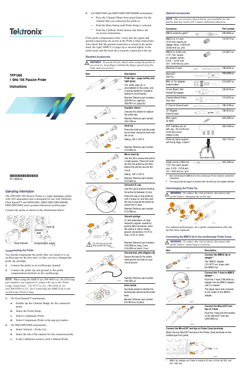
Operating informationThe TPP100010X Passive Probe is a high impedance probe with 10X attenuation that is designed for use with Tektronix FlexChannel™and MDO3000,MDO/MSO/DPO4000B,MSO/DPO5000series ground-referenced oscilloscopes.Connect the probe as shown in the illustrationsbelow.Compensating the ProbeYou should compensate the probe after you attach it to an oscilloscope for the first time,or after you have changed the probe tip cartridge.1.Connect the probe to an oscilloscope channel.2.Connect the probe tip and ground to the probe compensation terminals on the oscilloscope.NOTE.When using the MMCX tip (206-0663-xx),the following part numbers are required to connect the tip to the Probe Comp connections:131-9717-xx (1),196-3434-xx (1),and 206-0569-xx (2).See Connecting the MMCX tip to the oscilloscope Probe Comp.3.On FlexChannel™instruments:a.Double tap the Channel Badge for the connected probe.b.Select the Probe Setup.c.Select Compensate Probe.d.Select Compensate Probe in the pop up window.4.On MSO/DPO5000instruments:a.Select Vertical >Probe Cal....b.Select the tab of the channel for the connected probe.c.In the Calibration section,click Calibrate Probe.5.On MDO3000and MDO/MSO/DPO4000B instruments:Press the Channel Menu front panel button for the channel that you connected the probe to.Push the More button until Probe Setup is selected.Push the Calibrate Probe button and follow the on-screen instructions.If the probe compensation fails,verify that the signal and ground connections are secure at the Probe Comp connections.Also check that the ground connection is secure at the probe head,the rigid,MMCX or pogo tip is secured tightly in the probe head,and the hook tip is securely connected to the tip.StandardaccessoriesWARNING.To avoid electric shock when using the probe or accessories,keep fingers behind the finger guard of probe body and accessories.ItemDescriptionProbe tips –pogo (white)and rigid (gray)The white pogo tip ispre-installed on the probe,and is spring-loaded for compliant testing of circuit boards.Reorder Tektronix part numbers:206-0610-xx (rigid tip)206-0611-xx (pogotip)Insulator sleeveUnscrew this sleeve to replace the probe tips.Reorder Tektronix part number342-1194-xx Hook tipPress the hook tip onto the probe tip and then clamp the hook onto the circuit.Rating:300V CAT II Reorder Tektronix part number013-0362-xx Micro hook tipUse this tip to access test points in tight spaces.Press the hook tip onto the probe tip and then extend the pincers around the circuit.Rating:300V CAT II Reorder Tektronix part number013-0363-xx Universal IC capUse this cap to prevent shorting the probe tip between IC pins.Press the cap on the probe tip until it snaps on,and then spin the cap to expose the probe tip toward the IC lead.Reorder Tektronix part number013-0366-xx Ground springsTo limit aberrations on high frequency signals caused by ground path inductance,bend the spring to reach nearby ground connections (<0.75in,long;<0.25in,short).Reorder Tektronix part numbers:016-2028-xx (long,2ea.)016-2034-xx (short,2ea.)Ground lead,with alligator clip Secure the lead to the probe head ground and then to your circuit ground.Reorder Tektronix part number196-3521-xx Color bandsUse these bands to identify the oscilloscope channel at the probe head.Reorder Tektronix part number 016-0633-xx (5pairs)Optional accessoriesNOTE.The accessories shown below are available for the probes and are rated ≤30V unless indicated otherwise.AccessoryPart number MMCX probe tip (gold)1206-0663-xx MMCX to 0.1-inch (2.54mm)square pin adapter (blue),0.025-inch (0.635mm)sq.pins 131-9717-xxMMCX to 0.062inch (1.57mm)square pin adapter (white),0.016-0.018inch (0.4-0.46mm)sq.pins 131-9677-xxElectricalY-Lead 196-3434-xx MicroCKT TestTip206-0569-xx BNC to Tip Adapter,Unterminated 013-0367-xx Circuit Board Test Point/PCBAdapter 016-2016-xx Chassis-Mount Probe TestJack131-4210-xx 6”Clip-on GroundLead 196-3198-xx 12”Alligator GroundLead 196-3512-xx Wire,spool,32AWG020-3045-xx DUT Interface pin kit with (qty.20)0.018inch (0.46mm)round solder-inpins020-3169-xxProbe tip tripod support with living hinge,2each2352-1170-xxSolder aid for 0.062-inch (1.57mm)pitch square pins,0.016-0.018-inch (0.4-0.46mm)sq.pins003-1946-xx1See Connecting the MMCX tip to the oscilloscope Probe Comp for connection instructions.2The tripod probe tip support is pictured with the probe tip and adapter attached.Interchanging the ProbeTipWARNING.To reduce the risk of shock,disconnect the probe before changing the probetips.For optimal performance,do a probe compensation after the tip has been replaced.Connecting the MMCX tip to the oscilloscope ProbeCompWARNING.To reduce the risk of shock,disconnect the probe before connecting accessories.ItemDescriptionConnect the MMCX tip to adapter 1The MMCX adapter(131-9717-xx)snaps onto the MMCXtip.Connect the Y–lead to MMCX adapter 1Push the Y–lead (196-3434-xx)adapter into the MMCX adapter until it is seated.The signal input (red)connects to the center of the MMCXadapter.Connect the MicroCKT test tips to Y-leadPush the Y-lead into the handles of the MicroCKT test tips (206-0569-xx).Connect the MicroCKT test tips to Probe Comp terminals Attach the two MicoCKT test tips to the Probe Comp terminals on the ocsilloscope frontpanel.1MMCX tip,adapter,and Y-lead is limited to 30vrms,42Vpk,60VDC,and OVT <500Vpk.TPP10001GHz 10X Passive Probe Instructions*P071280904*071-2809-04Electrical and mechanical speci ficationsCharacteristic Speci fication Bandwidth (–3dB)1GHz System rise time (typical)<450psSystem input capacitance Rigid and MMCX tip:3.9pF ±0.3pF Pogo pin tip:5.1pF ±0.5pF System attenuation accuracy 10:1±2.2%Probe series resistance @DC 9.75M Ω±0.5%System input resistance @DC 10M Ω±2%Propagation delay ~5.67ns Maximum input voltage 300V RMS CAT II 1Cable length1.3m ±3cm1MMCX tip,adapter,and Y-lead is limited to 30vrms,42Vpk,60VDC,and OVT <500Vpk.PerformancegraphsEnvironmental speci ficationsCharacteristics DescriptionTemperature Operating Nonoperating –15°C to +65°C (+5°F to +149°F)–62°C to +85°C (–80°F to +185°F)Humidity Operating5%to 95%relative humidity (%RH)up to +30°C,5%to 75%RH above +30°C up to +65°C.NoncondensingNonoperating 5%to 45%RH above +65°C up to +85°C.NoncondensingAltitude Operating Nonoperating3.0km (9,842ft)maximum 12.2km (40,000ft)maximum Certi fications and compliancesCharacteristics Description EUDirectivesCompliance was demonstrated to the following speci fication as listed in the Of ficial Journal of the European Communities:Low Voltage Directive 2014/35/EU:EN61010-031/A1:2008RoHS Directive 2011/65/EUMeasurement Category Product ExamplesCAT III:Distribution-level mains,fixed installation CAT II:Local-level mains,appliances,portable equipmentCAT I:Circuits not directly connected to mains.Pollution Degree 2Do not operate in environments where cond-uctive pollutants may be present (as de fined in IEC 61010-1).Rated for indoor use only.Additional Safety StandardsUL61010-031;2010CAN/CSA C22.2No.61010-031:07/A1:2010IEC61010-031;IEC61010-031/A1:2008Equipment Recycling.This product complies with the European Union’s requirements according to Directive 2012/19/EU on waste electrical and electronic equipment (WEEE).For more information about recycling options,check the Support/Service section of the Tektronix Web site (/productrecycling).Safety summaryReview the following safety precautions to avoid injury and prevent damage to this product or any products connected to it.To avoid potential hazards,use this product only as speci fiing the probe or accessories in a manner not speci fied could result in a shock or fire hazard.This product is intended for use by professionals and trained personnel only;it is not designed for use in households or by children.To avoid fire or personal injuryGround-Referenced Oscilloscope Use.Do not float thereference lead of this probe when using with ground referenced oscilloscopes (for example,MDO,MSO,and DPO series oscilloscopes).The reference lead must be connected to earth potential (0V).Connect and Disconnect Properly.Connect the probe output to the measurement instrument before connecting the probe to the circuit under test.Disconnect the probe input and the probe reference lead from the circuit under test before disconnecting the probe from the measurement instrument.Avoid Electric Shock.To avoid injury or loss of life,do not connect or disconnect probes or test leads while they are connected to a voltage source.Observe All Terminal Ratings.To avoid fire or shock hazard,observe all ratings and markings on the product.Consult the product manual for further ratings information before making connections to the product.Avoid Electric Shock.When using probe accessories,never exceed the lowest rating of the probe or its accessory,whichever is less,including the measurement category and voltage rating.Avoid Electric Overload.To avoid injury or fire hazard,do not apply potential to any input,including the reference inputs,that varies from ground by more than the maximum rating for that input.Avoid Exposed Circuitry and Do not Operate Without Covers.Do not touch exposed connections and components when power is present.Inspect The Probe And Accessories.Before each use,inspect probe and accessories for damage (cuts,tears,defects in the probe body,accessories,cable jacket,etc.).Do not use if damaged.Do Not Operate in Wet/Damp Conditions.Do Not Operate in an Explosive Atmosphere.Keep Product Surfaces Clean and Dry.Safety Terms and Symbols Terms in This Manual.These terms may appear in thismanual:WARNING.Warning statements identify conditions or practices that could result in injury or loss oflife.CAUTION.Caution statements identify conditions or practices that could result in damage to this product or other property.Symbols on the Product.These symbols may appear on theproduct:Contacting TektronixWeb site: Phone:1-800-833-9200Address:Tektronix,Inc.Department or name (if known)14200SW Karl Braun Drive P.O.Box 500Beaverton,OR 97077USA Email:*************************Warranty informationFor warranty information,go to /warranty.Copyright ©Tektronix,Inc.All rights 。
路利达记录仪说明书

路利达记录仪说明书
1.插入存储卡。
(面对摄像头,机身左侧有表明“TP”的卡槽,存储卡的缺口朝上、金属条朝前对准卡槽轻轻推入即可,取出时轻按一下,卡会自动弹出)
2.安装电池。
将电池充满电后,按电池上箭头指示方向装入电池(注意电池上金属条对准机内金属触点,电池盖在机器尾部,将开关推至“ON”可轻轻揭开,电池充电方法见说明书)
3.开机。
按住机器左侧最上面电源键不放,约1秒钟即可开机。
同样在开机状态下,重复此操作即可关机。
4.设置。
面对屏幕机身左侧“MENU"为菜单键,按下它可根据高亮条提示,设置机器各种功能参数。
(机器参数已设置好,一般不要调整)
5.录像。
在开机状态下,面对屏幕,按机身顶部左侧“M”切换到录像功能,看屏幕左上方出现录像机图标时,按下机身顶部右侧“OK"键录像开始,这时屏幕左上方出现红点闪烁,表示录像开始,如要同时录音,短按一下电源键(注意,长按是关机),如要停止录像再次按下“OK"键。
6.照相。
切换“M"”键看到屏幕左,上方出现照相机图标时,按下“OK听到“咔嚓”声音表示拍照成功。
7.回放。
切换“M"键,如屏幕左上角出现“箭头”符号,按机身左侧上下箭头键可翻看照片;如屏幕左上角出现“胶片”符号,按“OK"键可回看录像。
8.数据管理。
完成的录像和照片资料可通过USB数据线导入电脑,也可将存储卡取出,使用读卡器复制到电脑。
- 1、下载文档前请自行甄别文档内容的完整性,平台不提供额外的编辑、内容补充、找答案等附加服务。
- 2、"仅部分预览"的文档,不可在线预览部分如存在完整性等问题,可反馈申请退款(可完整预览的文档不适用该条件!)。
- 3、如文档侵犯您的权益,请联系客服反馈,我们会尽快为您处理(人工客服工作时间:9:00-18:30)。
� 采用 64MB 大容量的 FLASH 闪存芯片存贮历史数据,掉电永不丢
失数据;
� 全隔离万能输入,可同时输入多种信号,无需更换模块,通过软件
参数设置即可;
� 显示工程量数据的数值范围更宽可显示 6 位数值: -999, 99~1999.99; � 可以参数设置、显示工程位号,工程单位,有流量累积; � 具有闪动报警显示,同时指示各路通道的下下限、下限、上限、上
注:实际功耗与仪表总通道数有关
3.7 环境及其他 � 工作温度范围:0℃ ~50℃ � 储藏温度范围:-20℃~70℃ � 工作湿度范围:低于 85%R.H,无结露 � 仪表的重量(64 通道) :最大约 2.8Kg 3.8 记录时间
记录时间的长短与 FLASH 存储器容量、 记录间隔和输入点数有关, 计算公式如下:
3.3 报警输出及变送输出 � 继电器输出:触点容量 AC 220V,3A,阻性负载 � 12 点可参数设置输出,可按通道的各报警点值设定 � 可参数设置 8 点变送输出,光电隔离,误差小于± 0.2% F ·S ,电流输
出负载能力≤450Ω 电压输出配接设备阻抗:需大于 2KΩ
3.4 外供电源 � DC 24V 电源:用于给变送器供电,最大负载能力≤200mA
管理软件外,还支持 MCGS 、参数设置王等流行参数设置软件;
� 采用新型开关电源,能在交流电源 AC 85V~265V 宽电压范围内正常工
作;
� 提供变送器 DC 24V 隔离配电; � 通过 EMCIII 级,保证仪表在恶劣的环境中正常工作。
3
TP1000 记录仪·使用手册
三、 技术指标
3.1.显示 � 10.1 寸彩色 TFT 触摸 LCD 或 7 寸彩色 TFT 触摸 LCD � 数字显示画面、棒图显示画面、实时曲线画面、追忆曲线画面共四个
满足用户现场打印的需求;
� 配备标准 USB2.0 接口。可使用鼠标键盘方便操作,输入历史数据转
存快捷方便,
2
TP1000 记录仪·使用手册
� 标准串行通讯接口, 带光偶隔离的 RS485 和 RS232C 以及以太网; � 支持标准 ModBus RTU 通讯协议(选配功能) ,除支持本公司数据
5.6 (棒图)棒图显示画面
目
录
一、概述 ........................................................................................... 1 2 二、 功能特点 .................................................................................. ..................................................................................2 3 三、 技术指标 .................................................................................. ..................................................................................3 6 四、安装与接线................................................................................ ................................................................................6 五、仪表运行及操作 ........................................................................ 9 六、仪表参数设置 .......................................................................... 19 25 七、故障分析及排除 ....................................................................... .......................................................................2
10
TP1000 记录仪·使用手册 下限报警。报警值可以在参数设置里设置。
显示画面下按钮功能介绍: 在界面底端有是四个按钮(保存、棒图、曲线界面、报警界面、设置) 。 保存:保存参数设置的当前值作为初始值并写入磁盘,防止突然断电而无 法保存。 棒图:切换按钮,按下此按钮可以切换到棒图界面。 曲线界面:切换按钮,按下此按钮可以切换到曲线界面。 报警界面:切换按钮,按下此按钮可以切换到报警界面。 设置:通过此按钮可以进入参数设置和系统设置。
5.3 开机画面 屏幕会显示点击屏幕进入启动属性窗口,这时我们不需要去点击屏 幕,让屏幕直接进入显示
5.4 总貌画面
总貌画面可以对当前的状况有比较全面的了解,包括测量名称,测量值, 工程量单位,输入信号类型,报警指示,报警输出状态等。画面的形式如下:
9
TP1000 记录仪·使用手册
5.5(数显)数字显示画面
4.3 输入信号接线
7
TP1000 记录仪·使用手册
8
TP1000 记录仪·使用手册
五、仪表运行及操作
本触摸型数据记录仪具有多个操作显示画面和参数设置界面,显示清晰、 信息量大、参数设置方便。用户无需专业培训就可以方便地操作使用仪表。仪 表接上电源后显示系统初始化画面。初始化系统完毕,进入总貌画面。下面分 别就仪表的键盘操作、各操作显示画面、各参数设置画面分别加以介绍。
上限报警;12 路继电器报警输出;
� 可参数设置 8 点变送输出,光电隔离,误差小于±0.2% F ·S; � 显示精度高,基本误差为±0.2% F ·S; � 温压补偿,支持补偿信号输入、常数可选,提供多种补偿模型,如
过热蒸汽,饱和蒸汽、压力补偿等常用补偿模型;
� 内置 GB2312 汉字库,使用全拼输入法输入; � 支持外接微型打印机,手动打印数据、曲线,自动定时打印数据,
5.1 运行画面
数据记录仪运行过程中所显示的画面为运行画面,包括总貌画面、数显画 面、 棒图画面、 实时曲线画面;画面设置(按画面键进入): 累积报表、 追忆画面、 报警记录、系统参数设置、报警参数设置、打印参数设置、等画面。其中数显 画面、棒图画面、 (实时)曲线画面为常用的基本画面。右上角为当前的日期及 时间。
电流输出(4~20) mA, (0~10) mA, (0~20) mA 可选。 电压输出 (0~24) V, 其他电压可选。 出厂默认设定为(0~24 )V, 其他类型订货时注明。
1
TP1000 记录仪·使用手册
二、 功能特点
本产品显示信息量大、界面友好、操作简单,下面是主要功能特点:
� 不需要笔和纸记录,日常维护工作量非常小,运行费用低; � 采用高亮度触控彩色 TFT 液晶屏,CCFL 背光、画面清晰; � 采用 ARM 微处理器, 可同时实现多路(1001 型为仪器内部最高 64 路,
� 可配备不同类型的智能通道板,根据应用要求选择。 � 内置大容量 FLASH ,可通过 U 盘快速将 FLASH 中的数据转储到计
算机中。内置的 FLASH 的容量为 64M 字节,8 通道时若 20 秒记录 一次可记录 865 天 ,最快 1 秒记录一次所有通道的数据。
� 数字显示画面、棒图显示画面、实时曲线画面、追忆曲线画面 � 追忆曲线读数光标功能。 � 测量、显示基本误差:± 0.2% F· S � 可参数设置 12 点报警功能。 � 可参数设置 8 点变送输出,光电隔离,误差小于±0.2% F ·S
TP1000 记录仪·使用手册
一、概述
触控数据记录仪以其丰富的显示画面、灵活的操作方式以及强大的记录、 运算、控制和管理功能,在各行各业中获得了极其广泛的应用。本产品吸纳了 各种国内外数据记录仪的优点,应用最新的显示技术、微电子技术、数据存储 和通讯技术,是一款功能齐全、操作方便、精确可靠、高性价比的产品。 本产品配置丰富,有蓝屏和彩色两种显示屏。可以接收多种类型的直流电 流、电压和电阻信号,实现温度、湿度、压力、液面、流量、成分以及力、力 矩、位移等物理量的显示、记录、越限监控、报表生成、数据通讯、信号变送 以及流量累计等功能。 本产品主要由触控液晶屏、按键、ARM 微处理器为核心的主板、主电源、 外供变送器电源、智能通道板、大容量 FLASH 等构成:
外形尺寸:288×288×200mm(长×宽×深) 安装开孔尺寸 278×278mm
4.2 接线端子图
1.交流 AC96-240V 电源输入端子
6
TP1000 记录仪·使用手册 2.直流 DC24V 输入端子 3.直流 DC24V 输出以及 485 信号输入端子
4.提手 5.RS232 接口 九针串口接线为: �第 2 针为仪表的 “ RXD ” (RS232 的收或 RS485 A+ ) , 第 3 针为仪表的 “TXD ” (RS232 的发或 RS485 B-) ,5 针为仪表的通讯“地” 。 �如外接微型打印机,应将 3 针接到打印单元的 PA 上, 5 针接到打印单元的 PB 上。 6.以态网接口 7.测量装置安装插槽 8.固定测量装置螺丝
基本画面
� � � �
基本误差小于±0.2%F·S,数字显示范围-999.99~1999.99 测量分辨力:1/60000,24 位 AD 转换器 实时曲线记录间隔 1 秒~9999 秒,对应整屏曲线时间 30 秒~300 分 追忆曲线记录间隔从 1 秒到 9999 秒连续可设