SolidWorks创新日:设计无极限
solidworks在数字化设计中的作用

一、概述在当今数字化时代,各行各业都在不断追求技术的创新和发展。
数字化设计作为现代工程设计的一种重要手段,已经成为工程设计领域中不可或缺的一部分。
SolidWorks作为一款领先的三维计算机辅助设计(CAD)软件,正日益受到行业的认可和重视。
本文主要探讨SolidWorks在数字化设计中的重要作用及其对工程设计的影响。
二、SolidWorks的功能和特点1. SolidWorks作为一款领先的CAD软件,具有强大的三维建模功能,可以对复杂的工程结构进行精确建模,提高设计的精度和效率。
2. SolidWorks还拥有丰富的设计工具和功能模块,可以对不同类型的设计任务进行灵活处理,满足工程师在设计过程中的各种需求。
3. SolidWorks的协同设计功能,使得多人在同一项目上进行协作成为可能,提高了工程设计团队的工作效率和协调能力。
三、SolidWorks在数字化设计中的作用1. 提高设计效率SolidWorks可以有效地利用三维建模技术来提高设计效率。
通过SolidWorks软件,工程设计师可以快速、准确地对产品的外观和结构进行模拟和设计,缩短产品设计周期,降低产品开发成本。
2. 预测产品性能SolidWorks还可以对产品的性能进行模拟分析,包括结构强度、热特性、流体流动等方面。
通过对产品的性能进行模拟分析,可以在产品设计的早期阶段发现潜在的问题,避免在后期出现不必要的调整和修正。
3. 优化产品结构SolidWorks可以通过有限元分析等技术手段,对产品的结构进行优化设计。
通过对产品结构进行优化,可以减轻产品的重量、提高产品的强度和稳定性,满足产品在使用过程中的各种要求。
4. 实现数字化协作SolidWorks具有优秀的协同设计功能,可以实现工程设计团队的数字化协作。
团队成员可以在同一项目上进行实时协作和交流,共同完善产品设计方案,提高团队的工作效率。
5. 提供全面的设计文档SolidWorks可以生成全面的设计文档,包括工程图纸、零部件清单、装配图等。
SOLIDWORKS:企业数字化理念的全面升级
SOLIDWORKS:企业数字化理念的全面升级SOLIDWORKS是一款强大的计算机辅助设计(CAD)软件,致力于提供全方位的数字化解决方案,在企业数字化的升级中扮演着重要的角色。
SOLIDWORKS积极倡导数字化转型,为企业提供一系列数字化工具,旨在提高效率、降低成本、加快产品上市节奏。
一、数字化原型快速创建传统的产品制造一直依赖于模型的原型制作,但是这个过程通常是非常耗时的。
而SOLIDWORKS提供了数字化原型快速创建的功能,企业可以借由该功能进行快速化设计,提高设计和产品开发的效率。
另外,数字化原型的优势就在于减少了人为因素对产品开发过程中的干预,产品的实现和测试更加精确以及节省了大量时间。
二、智能部件库的协作SOLIDWORKS提供的智能部件库可以将零部件整合到一起,使得协作开发效率更加高效。
无论是开发者或设计者,他们都能够轻松地提取所需的信息,方便快捷地进行数字化部件设计,大大提高了制造效率和产品质量,客户满意度大大提高。
三、自动化制造生产数字化转型中的自动化制造生产是目前的趋势,SOLIDWORKS提供了自动化工具的支持,借助集成化的工具、模块和设计软件,可以快速创建和测试模型的新方法。
此外,企业还可采用自动化制造生产等软件作为链接供应链的方式,可以实现准确、迅速地生产高质量的产品,同时降低运作成本。
四、产业零部件库的开发SOLIDWORKS采用产业零部件库的开发方式,让企业能够快速、方便地制作产品。
同时,这种开发方式能够快速的满足客户需要的需求,让企业在产品开发和建模方面拥有了更强的竞争力。
产业零部件库通过专业的管控,可以实时掌握当前企业需求,为企业提供最富创造力的解决方案,更能够适应于市场快速变化的需求。
总之,SOLIDWORKS在企业数字化理念的升级中扮演着至关重要的角色,提供了众多高效、便捷、实用的工具和应用,为企业创造了更快大、更高效的生产效率。
企业要在数字化转型中不断寻求创新,与时俱进,与SOLIDWORKS一道,共创更美好的数字化未来。
SOLIDWORD软件

SOLIDWORD软件SolidWorks百科名⽚SolidWorks为达索系统(Dassault Systemes S.A)下的⼦公司,专门负责研发与销售机械设计软件的视窗产品。
达索公司是负责系统性的软件供应,并为制造⼚商提供具有Inter net整合能⼒的⽀援服务。
该集团提供涵盖整个产品⽣命周期的系统,包括设计、⼯程、制造和产品数据管理等各个领域中的最佳软件系统,著名的CATIAV5就出⾃该公司之⼿,⽬前达索的CAD产品市场占有率居世界前列。
SolidWorks详细简介SolidWorks公司成⽴于1993年,由PTC公司的技术副总裁与CV公司的副总裁发起,总部位于马萨诸塞州的康克尔郡(Concord,Massa chusetts)内,当初所赋予的任务是希望在每⼀个⼯程师的桌⾯上提供⼀套具有⽣产⼒的实体模型设计系统。
从1995年推出第⼀套SolidWorks三维机械设计软件⾄今,它已经拥有位于全球的办事处,并经由300家经销商在全球140个国家进⾏销售与分销该产品。
SolidWorks软件是世界上第⼀个基于Windows开发的三维CAD系统,由于技术创新符合CAD技术的发展潮流和趋势,SolidWorks公司于两年间成为CA D/CAM产业中获利最⾼的公司。
良好的财务状况和⽤户⽀持使得SolidWorks每年都有数⼗乃⾄数百项的技术创新,公司也获得了很多荣誉。
该系统在1995-1999年获得全球微机平台CAD系统评⽐第⼀名;从1995年⾄今,已经累计获得⼗七项国际⼤奖,其中仅从1999年起,美国权威的CAD专业杂志CADENCE连续4年授予So lidWorks最佳编辑奖,以表彰SolidWorks的创新、活⼒和简明。
⾄此,SolidWorks 所遵循的易⽤、稳定和创新三⼤原则得到了全⾯的落实和证明,使⽤它,设计师⼤⼤缩短了设计时间,产品快速、⾼效地投向了市场。
由于SolidWorks出⾊的技术和市场表现,不仅成为CAD⾏业的⼀颗耀眼的明星,也成为华尔街青睐的对象。
SolidWorks设计仿真日2012在佛山圆满举办
SolidWorks设计仿真日2012在佛山圆满举办
无
【期刊名称】《模具工程》
【年(卷),期】2012(000)006
【摘要】近日,由广州腾软信息科技有限公司主办的Solidwolrks 2012设计仿真日佛山站在金茂华美达广场酒店成功召开。
这次会议上,
【总页数】1页(P17-17)
【作者】无
【作者单位】不详
【正文语种】中文
【中图分类】TP391.9
【相关文献】
1.2012世界高血压日活动在澳圆满举办 [J], 无
2.腾软Solid Works设计仿真日2012圆满举办 [J],
3.聆听设计仿真前沿的强音——记DS SOLIDWORKS 2017设计仿真日 [J], 向飞
4.SolidWorks2008设计仿真日在上海举办 [J],
5.SolidWorks举办2008设计仿真日 [J],
因版权原因,仅展示原文概要,查看原文内容请购买。
SOLIDWORKS:企业数字化理念的全面升级
SOLIDWORKS:企业数字化理念的全面升级随着数字化时代的到来,越来越多的企业开始意识到数字化转型的必要性。
数字化转型并不只是单纯的使用新技术,而是一种全面升级的理念,涉及到企业的组织结构、经营模式、服务方式等多个方面。
SOLIDWORKS是一家致力于数字化设计和制造的软件公司,其协同设计平台可以帮助企业有效实现数字化转型。
本文将介绍SOLIDWORKS是如何实现企业数字化理念的全面升级的。
一、产品数字化设计SOLIDWORKS提供全面的数字化设计工具,支持从最初的草图到最终的3D产品设计。
SOLIDWORKS的3D CAD软件有助于设计师通过数字化的方式将产品设计出来,减少了传统手工设计过程中的误差和不确定性。
SOLIDWORKS的数字化设计工具还支持产品模拟分析,可以帮助企业提前发现任何设计缺陷和问题,从而避免浪费成本和时间。
二、数据数字化管理传统的管理方式往往需要大量的人力资源和时间,而且容易出现数据丢失、误差等问题。
数字化管理则完全不同,它可以帮助企业更好地管理和分析数据,提高企业的管理效率和工作效率。
SOLIDWORKS的数据管理工具可以帮助企业实现数字化管理,包括版本控制、共享数据、任务分配、权限管理等功能。
三、制造数字化流程制造数字化流程是指通过数字化技术将制造的整个流程数字化,实现从设计到生产的无缝衔接。
SOLIDWORKS提供了可靠的CAM工具,可以帮助企业实现完整的数字化制造流程,包括数控加工、3D打印等。
SOLIDWORKS的CAM工具还支持工艺规划、刀具路径设置、工具管理等功能,可以帮助企业提高生产效率和质量。
数字化协同设计是一种可以帮助企业实现团队合作、协同工作、提高效率的方法。
SOLIDWORKS的协同设计平台可以帮助团队成员在一个数字化环境中协同工作,可以随时与他人共享文件、查看和评论设计图纸,在一个平台上集成所有的数据和工具,提高生产效率和质量。
总之,数字化转型已经成为当今企业发展的趋势,SOLIDWORKS作为数字化设计和制造的领导者,可以帮助企业在数字化转型过程中获得更多的价值。
【最新】SOLIDWORKS2017十大新功能
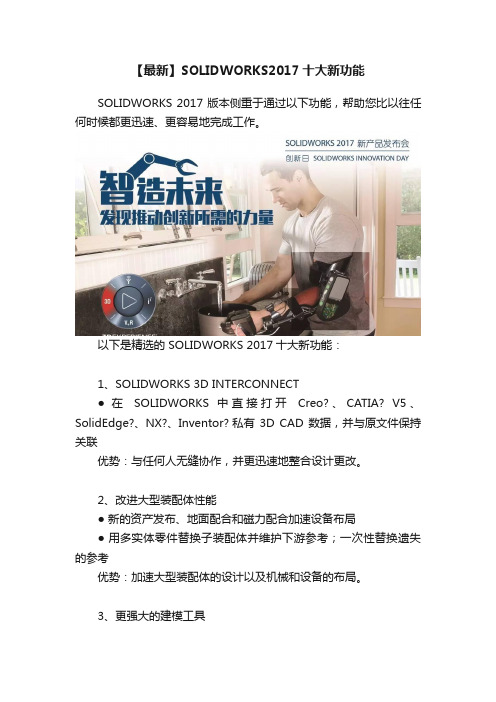
【最新】SOLIDWORKS2017十大新功能SOLIDWORKS 2017 版本侧重于通过以下功能,帮助您比以往任何时候都更迅速、更容易地完成工作。
以下是精选的 SOLIDWORKS 2017十大新功能:1、SOLIDWORKS 3D INTERCONNECT●在SOLIDWORKS 中直接打开Creo?、CATIA? V5、SolidEdge?、NX?、Inventor? 私有3D CAD 数据,并与原文件保持关联优势:与任何人无缝协作,并更迅速地整合设计更改。
2、改进大型装配体性能●新的资产发布、地面配合和磁力配合加速设备布局●用多实体零件替换子装配体并维护下游参考;一次性替换遗失的参考优势:加速大型装配体的设计以及机械和设备的布局。
3、更强大的建模工具●新型高级异型孔向导创建/重用自定义孔●包覆特征现可用于任意曲面;支持多个面的在曲面上偏移 3D 曲线●钣金支持三折式圆角优势:用较少的选取和点击更快速、更轻松地建模。
4、VISUALIZE 改进渲染和动画●新的“Visualize Boost”:由于超快的渲染速度,网络渲染变得非常简单●导入动画和运动算例●映射 SOLIDWORKS 相机导航和热键●支持 HTC? Vive?、Oculus、Google? Cardboard、Samsung?优势:大幅提高渲染速度并改进建模、渲染和查看之间的工作流程。
5、更快创建 2D 工程图●参考并链接到注解中的 BOM 表单元格元素●无模型的参数化镜像工程图视图●预定义图层优势:简化、更快的工程图创建。
6、MBD 的扩充功能●对比两个修订版本的几何体和 3D PMI●更轻松地定义拔模零件 DimXpert 3D PMI●导出带有 3D PMI 的 STEP 242,以自动化 CAM 和 CMM●附加多个文件到 3D PDF 以建立技术数据包 (TDP)优势:从 2D 工程图轻松过渡到 MBD 并实现基于模型的企业 (MBE)。
SolidWorks 可持续设计:材料选择和可持续重设说明书

Engineering Designand Technology SeriesSolidWorks® Sustainable Design An Introduction to Material Choiceand Sustainable RedesignDassault Systèmes SolidWorks Corporation 300 Baker AvenueConcord, Massachusetts 01742 USA Phone: +1-800-693-9000Outside the U.S.: +1-978-371-5011Fax: +1-978-371-7303Email:******************* Web: /education© 1995-2009, Dassault Systèmes SolidWorks Corporation, a Dassault Systèmes S.A. company, 300 Baker Avenue, Concord, Mass. 01742 USA.All Rights Reserved.The information and the software discussed in this document are subject to change without notice and are not commitments by Dassault Systèmes SolidWorks Corporation (DS SolidWorks).No material may be reproduced or transmitted in any form or by any means, electronic or mechanical, for any purpose without the express written permission of DS SolidWorks.The software discussed in this document is furnished under a license and may be used or copied only in accordance with the terms of this license. All warranties given by DS SolidWorks as to the software and documentation are set forth in the SolidWorks Corporation License and Subscription Service Agreement, and nothing stated in, or implied by, this document or its contents shall be considered or deemed a modification or amendment of such warranties.Patent Notices for SolidWorks Standard, Premium, and Professional ProductsU.S. Patents 5,815,154; 6,219,049; 6,219,055;6,603,486; 6,611,725; 6,844,877; 6,898,560;6,906,712; 7,079,990; 7,184,044; 7,477,262;7,502,027; 7,558,705; 7,571,079, and foreign patents, (e.g., EP 1,116,190 and JP 3,517,643). U.S. and foreign patents pending.Trademarks and Other Notices for All SolidWorks ProductsSolidWorks, 3D , 3D ContentCentral, DWGeditor, PDMWorks, eDrawings, and the eDrawings logo are registered trademarks and FeatureManager is a jointly owned registered trademark of DS SolidWorks. SolidWorks Enterprise PDM, SolidWorks Simulation, SolidWorks Flow Simulation, and SolidWorks 2010 are product names of DS SolidWorks.CircuitWorks, DWGgateway, DWGseries, Feature Palette, FloXpress, PhotoWorks, TolAnalyst, and XchangeWorks are trademarks of DS SolidWorks. FeatureWorks is a registered trademark of Geometric Ltd.Other brand or product names are trademarks or registered trademarks of their respective holders.Document Number: PME0518-ENG COMMERCIAL COMPUTERSOFTWARE - PROPRIETARYU.S. Government Restricted Rights. Use, duplication, or disclosure by the government is subject to restrictions as set forth in FAR 52.227-19 (Commercial Computer Software - Restricted Rights), DFARS 227.7202 (Commercial Computer Software and Commercial Computer Software Documentation), and in the license agreement, as applicable.Contractor/Manufacturer:Dassault Systèmes SolidWorks Corporation, 300 Baker Avenue, Concord, Massachusetts 01742 USA Copyright Notices for SolidWorks Standard, Premium, and Professional ProductsPortions of this software © 1990-2009 Siemens Product Lifecycle Management Software III (GB) Ltd.Portions of this software © 1998-2009 Geometric Ltd.Portions of this software © 1986-2009 mental images GmbH & Co. KG.Portions of this software © 1996-2009 Microsoft Corporation. All rights reserved.Portions of this software © 2000-2009 Tech Soft 3D. Portions of this software © 1998-20093Dconnexion.This software is based in part on the work of the Independent JPEG Group. All Rights Reserved. Portions of this software incorporate PhysX™ by NVIDIA 2006-2009.Portions of this software are copyrighted by and are the property of UGS Corp. © 2009.Portions of this software © 2001-2009 Luxology, Inc. All Rights Reserved, Patents Pending. Portions of this software © 2007-2009 DriveWorks Ltd.Copyright 1984-2009 Adobe Systems Inc. and its licensors. All rights reserved. Protected by U.S. Patents 5,929,866; 5,943,063; 6,289,364; 6,563,502; 6,639,593; 6,754,382; Patents Pending.Adobe, the Adobe logo, Acrobat, the Adobe PDF logo, Distiller and Reader are registered trademarks or trademarks of Adobe Systems Inc. in the U.S. and other countries.For more copyright information, in SolidWorks see Help > About SolidWorks.Other portions of SolidWorks 2010 are licensed from DS SolidWorks licensors.Copyright Notices for SolidWorks Simulation Portions of this software © 2008 Solversoft Corporation.PCGLSS © 1992-2007 Computational Applications and System Integration, Inc. All rights reserved. Portions of this product are distributed under license from DC Micro Development, Copyright © 1994-2005 DC Micro Development, Inc. All rights reserve1: Introduction and Material Choice (1)Using This Book (2)What is SolidWorks Software? (2)Prerequisites (2)Conventions Used in This Book (3)Sustainability Options 4Materials (4)Manufacturing (Parts) (4)Process (4)Use (4)Manufacturing and Transportation (Assemblies) (5)Manufacturing (Assemblies) (5)Transportation and Use (Assemblies) (5)Environmental Impact (5)Carbon Footprint (5)Energy Consumption (6)Air Acidification (6)Water Eutrophication (6)Report (6)Baseline (7)Color Coding (7)Material Choice in Sustainable Design (8)The lifetime of a cup (8)Environmental Impacts (9)Impact vs. Lifetime (10)12: Sustainability and Simulation (12)Using Simulation (13)How to Activate Simulation with Sustainability (14)Activating Simulation and Sustainability (14)Mating Assembly (16)Remating Metal Outside (16)Analysis of Insulation (19)What makes good Thermal Insulator? (19)Plastic (19)Metal (20)Plastic and Metal (20)Static Simulation (21)Static Study 1 (21)Static Study 2 (25)Thermal Study (30)Wall and Base Redesign (34)Redesign of Base (35)Simulation of Redesign (36)Looking at Sustainability (38)Conclusion (39)Lesson 1 Introduction and Material ChoiceWhen you complete this lesson, you will be able to:Q Describe the relationship between Sustainability and SolidWorks;Q Identify the principle components of the Sustainability Add-in;Q Explain significance of Material choice and environmental impacts.Using This BookSolidWorks Sustainability An Introduction to Sustainable Designhelps you learn the principles of using Sustainability and Sustainability as integral parts of a creative and iterative design process.For this project, You will “learn by doing” as you complete a structural analysis.What is SolidWorks Software?SolidWorks is design automation software. In SolidWorks, you sketch ideas and experiment with different designs to create 3D models using the easy to learnWindows® graphical user interface.SolidWorks is used by students, designers, engineers and other professionals toproduce single and complex parts, assemblies and drawings.PrerequisitesBefore you begin the SolidWorks Sustainability An Introduction toSustainable Design you should complete the following online tutorials thatare integrated in the SolidWorks software:Q Lesson 1 - Parts-Set 1Q Lesson 2 - Assemblies-Set 1Q Designing for Sustainability-Set 2Q Simulation - Static AnalysisQ Simulation - Thermal AnalysisYou can access the online tutorials by clicking Help, SolidWorks Tutorials, AllSolidWorks Tutorials (Set 1) and Simulation Tutorials by clicking Help,SolidWorks Simulation, Tutorials. The online tutorial resizes the SolidWorkswindow and runs beside it.As an alternative, you can complete the following lessons from An Introduction to Engineering Design With SolidWorks:Q Lesson 1: Using the InterfaceQ Lesson 2: Basic FunctionalityQ Lesson 3: The 40-Minute Running StartQ Lesson 4: Assembly BasicsQ Lesson 6: Drawing BasicsConventions Used in This BookThis manual uses the following typographical conventions:Sustainability OptionsHere we will go through the Sustainability interface and different menus as wellas define various terms used within the SolidWorks Add-In. There are four main menus, Material, Manufacturing, Transportation and Use, and Environmental Impact.First, we will start SustainabilityXpress.1Start Sustainability.Click Tools, Add-Ins, Check Sustainability.Note: A Part or Assembly needs to be open to view Sustainability. When you first open the Add-In, everything should be black except for the regions.MaterialsIn this option you can choose between differentmaterials for the specific part using the drop downmenus. You are also able to search for alternativematerials using the Find Similar option. You can alsoassign a material of your choice to the part.Manufacturing (Parts)The Manufacturing section includes Process and Use to define world locations. ProcessIn this option, there is a drop down menu labeledProcess where the user can chose between multipledifferent production techniques to manufacture theirpart. There is also a world map. The world map is forthe user to define where the part is going to be made.There are four different areas to choose from, NorthAmerica, Europe, Asia, and Japan.UseThe second world map is used in this menu. Here youare able to chose where your product will be transportedto after production. The further the distance betweenmanufacturer and user the less environmentally friendly.Note:All the regions for Manufacturing and Use are the same.Manufacturing and Transportation (Assemblies)Within Assemblies the Sustainability interface changes slightly. Manufacturing (Assemblies)The only difference from the manufacturing menu for apart is that it does not have a process drop down menuinstead the user is only able to choose the ManufacturingRegion.Transportation and Use (Assemblies)With in this menu the user is given the ability to chose thePrimary Mode of Transportation (Train, Truck,Boat, or Plane). The user is also able to choose the Typeof Energy that will be used throughout the lifetime of theproduct. Like before in the Use menu for Parts the user isalso able to choose the Region the that product will beused.Environmental ImpactThis area includes four quantities: Carbon Footprint, Total Energy, AirAcidification, and Water Eutrophication. Each graph shows the user a graphic breakdown of Material Impact, Transportation and Use, Manufacturing, and End of Life.Carbon FootprintA measure of carbon-dioxide and other greenhouse gas emissionssuch as methane (in CO2 equivalent units, CO2e) which contributeto an emissions, predominantly caused by burning fossil fuels.Global warming Potential (GWP) is also commonly referred to as acarbon footprint.Energy ConsumptionA measure of the non-renewable energy sources associated with thepart’s life cycle in nits of mega joules (MJ). This impact includesnot only the electricity or fuels used during the product’s life cycle,but also the upstream energy required to obtain and process thesefuels, and the embodied energy of materials which would bereleased if burned. Energy Consumed is expressed as the netcalorific value or energy demand from non-renewable resources (e.g. petroleum, natural gas, etc.). Efficiencies in energy conversion (e.g. power, heat, steam, etc.) are taken into account.Air AcidificationSulfur dioxide, nitrous oxides other acidic emissions to air cause anincrease in the acidity of rain water, which in turn acidifies lakesand soil. These acids can make the land and water toxic for plantsand aquatic life. Acid rain can also slowly dissolve man-madebuilding materials such as concrete. This impact is typicallymeasured in nits of either kg sulfur dioxide equivalent (SO2e), ormoles H+ equivalent.Water EutrophicationWhen an over abundance of nutrients are added to a waterecosystem, eutrophication occurs. nitrogen and phosphorous fromwaste water and agricultural fertilizers causes an overabundance ofalgae to bloom, which then depletes the water of oxygen and resultsin the death of both plant and animal life. This impact is typicallymeasured in either kg phosphate equivalent (PO4e) or kg nitrogen(N) equivalent.ReportOn the very bottom of SustainabilityXpress, there are theGenerate Report and Email Report buttons. By clicking generate report, SolidWorks automatically creates a Word document about the current analysis. This analysis can be on anindividual material type and environmental impacts or it can be on a comparison of two different material types. The email report opens Microsoft Outlook for the user to send the word document to an email address.BaselineTo the right of the report buttons are theImport BaselineSet Baseline andbuttons. By clicking set baseline, SustainabilityXpress automatically takes themost recent material type and sets it as the material that every other material will be compared to. Otherwise, every time the user clicks on another material,SustainabilityXpress will automatically compare them and dynamicallyrecalculate the Environmental Impacts. Also, if there is no difference between the current and previous settings and materials then all of the Environmental Impacts will automatically turn green. Then, by clicking import baseline, the user canimport a saved SustainabilityXpress baseline from another part.Color CodingWhen Baseline is clicked, the environmental impacts turn colors to representdifferent states.Q Black represents the baseline material.Q Green indicates that the current material is more environmentally friendly than the baseline material.Q Red indicates that the current material is less environmentally friendly than the baseline material.Material Choice in Sustainable DesignHere we will decide which material is the correct material to use depending of the materials environmental impacts over its lifetime. In this example, imagine theanalysis of a cup.The lifetime of a cupThe material of a product significantly affects its lifetime. For example, a cupcould be made from paper, plastic, or metal. Depending on what material we use will decide how many times the cup can be used. For this example we will assume if we made the cup out of paper (we will be using pine because there is no papermaterial choice within SolidWorks that is linked with Sustainability) it could beused only once, a cup made from plastic can be used 10 times, and a cup madefrom metal could be used 1000 times.Environmental ImpactsWith the SolidWorks model we have for a simple cup, we have created threedifferent configurations, one for each material type. We activated Sustainabilityand kept the Manufacturing and Transportation and Use the same continents forall three configurations.Here are the Environmental Impacts for each material:From these we will use the Total Energy as a baseline to examine which material is the most Sustainable for its lifetime. The results were as follows:Paper: 8.30E-3 MJPlastic: 2.51 MJMetal: 2.98 MJNow we need to see which material is the most environmentally friendly based on its lifetime. The Sustainability Calculator takes the values that we found for the Environmental Impacts (CO2, MJ, SO2, and PO4) and re calculates it intosomething that is easier for us to understand (example: miles driven in a car orhours watching tv).To start, we will open the Sustainability Calculator.3Go to /sustainability/products/calculator/index.htm.4Click Energy Consumption.5Click hours of watching TV.Impact vs. LifetimeHere we will discuss whether the Lifetime of the material is more important than its Environmental Impacts.Using the Sustainability Calculator we will use the three Energy values we gotfrom SolidWorks Sustainability and calculate which material is the best for theenvironment according to its lifetime.In order to do this we need to use the Lifetime values we discussed earlier. Instead of using the number of times each cup can be used we will use the number of cups that need to be made to equal one Metal cup. This means 1000 paper cups and 10 plastic cups need to be made to equal one Metal cup.Now, go back to the Sustainability Calculator and find the Current Design box.2Enter numbers.Enter the numbers given for the Values and Quantities and click Calculate. Note:You are only able to enter one set two sets of values. It would be easier to open three se per ate windows and compare the outcomes.Name: PaperValue: 8.30E-3Quantity: 1000Name: PlasticValue: 2.51Quantity: 10Name: MetalValue: 2.98Quantity: 1The Sustainability Calculator will calculate how many Hours of Watching TV is equivalent to produce these cups. You should get:Paper: 2 HoursPlastic: 6 HoursMetal: 1 Hour3Material Decision.When comparing materials according to their lifetimes and environmental impacts it is wise to chose the material that effects the environment the least compared to how long its lifetime is. In this case, it is wise to chose the Metal Cup. The Metal Cup can be used the longest and when compared to the Paper and Plastic Cups it the least harmful to the Environment based on the cups Energy Consumption.。
SolidWorks2024动画设计图文教程详解
SolidWorks2024动画设计图文教程详解SolidWorks是一款功能强大的3D设计软件,它可以用于创建各种机械和工业设计。
其中,动画设计是SolidWorks的一项重要功能,可以帮助设计师更好地展示产品的功能和流程。
本文将详细介绍SolidWorks 2024中动画设计的图文教程。
第一步是打开SolidWorks软件并创建一个新的文件。
点击菜单栏的“文件”,然后选择“新建”。
选择“Part”模板来创建一个新的零件文件。
第二步是设计产品的基本结构。
在图形界面的左侧工具栏中选择所需的工具,例如直线、圆形、矩形等,然后在绘图区域中绘制所需的几何形状。
根据产品的实际需求进行设计,并确保每个元素都与其他元素对齐和相交。
第三步是给产品添加所需的材质和外观。
在左侧工具栏中选择“材料”工具,然后在绘图区域中选择需要添加材质的部分,例如金属、塑料或玻璃。
选择合适的材质后,产品外观将发生相应的变化。
第四步是给产品添加动画。
点击菜单栏的“工具”,然后选择“运动研究”。
在弹出的对话框中选择“动作模拟器”,然后按照指示完成动画设置。
第五步是确定动画的的开始和结束位置。
在绘图区域中选择中央图标来定义动画的起始位置。
然后,在时间轴上选择动画结束时的位置。
通过调整时间轴中的滑块来控制动画的时间长度。
第六步是设置动画的路径。
在绘图区域中选择“路径”工具,在产品的路径上点选两个或多个点,并用线条将它们连接起来。
确保路径与产品的移动方向一致,并保持平滑的曲线。
第七步是为动画添加约束。
选择一些移动部件,然后在左侧工具栏中选择“配合驱动约束”工具。
选择需要与该部件配合运动的其他部件,然后通过添加关系和约束使它们按照所需方式运动。
例如,你可以设置一个连杆只能在一定范围内旋转,或者设置两个部件可以同时移动。
第八步是预览和调整动画。
点击菜单栏的“运行”按钮来预览动画效果。
在预览时,可以调整动画的速度和起始位置,并查看产品在不同时间点的状态。
SOLIDWORKS:企业数字化理念的全面升级
SOLIDWORKS:企业数字化理念的全面升级一、数字化理念的全面升级1. 云端设计和制造随着云计算和互联网技术的迅速发展,SOLIDWORKS将云端设计与制造纳入数字化理念升级的重点。
通过云端设计,用户可以随时随地使用SOLIDWORKS的3D设计软件进行产品设计,实现实时协作和远程工作。
而云端制造则可以让用户直接在云端进行工艺规划和数控编程,提高生产效率和降低成本。
这种云端设计和制造的方式,不仅可以满足企业日益增长的灵活性和高效性需求,还可以将生产制造的整个流程数字化,提供更加智能化的解决方案。
2. 设计数据智能化管理在数字化理念升级中,SOLIDWORKS将设计数据的智能化管理视为重要任务。
通过引入智能化的数据管理平台,可以对设计数据进行全面管理和监控,实现数据的统一存储、版本控制和权限管理。
这样一来,用户可以更加高效地查找和利用设计数据,避免出现数据冗余和不一致的情况,提高设计和制造的整体效率。
3. 智能制造解决方案随着人工智能和大数据技术的不断发展,智能制造成为数字化理念升级的又一重要方向。
SOLIDWORKS利用先进的人工智能和大数据技术,推出了智能制造解决方案,可以对制造流程进行全面优化和智能化改造。
通过人工智能技术,可以对生产设备进行智能监控和预测维护,以提高设备的利用率和降低维护成本;通过大数据技术,可以对生产过程进行全面分析和优化,提高生产效率和产品质量。
这种智能制造解决方案,可以帮助企业实现数字化工厂的建设和智能制造的转型,提升整体竞争力和市场影响力。
4. 开放性平台生态建设在数字化理念升级中,SOLIDWORKS将开放性平台生态建设作为重点任务,致力于构建一个开放、共享、互通的数字化平台。
通过开放API和标准协议,可以实现SOLIDWORKS与其他软件和硬件系统的无缝集成,为用户提供更加灵活和个性化的数字化解决方案。
SOLIDWORKS还通过开放的生态系统,积极引入第三方合作伙伴,共同推动数字化理念的升级和实践,加速数字化转型的进程。
SolidWorks机械设计的基本原则与方法

SolidWorks机械设计的基本原则与方法SolidWorks是一种普遍使用的三维机械设计软件,它在工程领域中被广泛应用于产品设计、制造、装配等方面。
为了有效利用SolidWorks进行机械设计,有一些基本原则和方法值得我们遵循和掌握。
首先,了解产品设计目标和需求是机械设计的基本原则之一。
在进行机械设计之前,我们必须明确产品的设计目标和需求,包括功能、外观、尺寸、材料等方面。
明确这些要求有助于我们在SolidWorks中选择适当的工具和功能,以满足设计需求。
其次,合理规划设计过程是SolidWorks机械设计的关键。
设计过程应该是有条不紊的,需要一定的规划和组织。
在设计之前,我们应该了解整体设计的步骤和流程,设定设计计划和时间表,并进行必要的前期准备工作,例如收集产品规格、素材和相关工程数据等。
第三,正确使用SolidWorks的基础功能和工具是机械设计的基本方法之一。
SolidWorks提供了丰富的功能和工具来支持机械设计。
例如,使用Part功能可以创建三维零件模型,使用Assembly功能可以进行装配设计,使用Drawing功能可以生成工程图等。
熟练掌握这些基础功能可以提高我们的机械设计效率和准确性。
第四,掌握SolidWorks建模技巧是机械设计的重要方法之一。
建模是机械设计的核心环节,通过建模可以创建精确的三维模型。
在SolidWorks中,我们可以使用各种建模工具进行实体建模、曲面建模等。
掌握正确的建模技巧可以帮助我们高效地创建复杂的模型,并提高设计质量。
第五,合理使用装配功能是SolidWorks机械设计的重要方法之一。
在实际机械设计中,通常需要进行多个零件的装配。
SolidWorks提供了装配功能,可以将多个零件组装在一起,并进行动画演示和碰撞检测等操作。
合理运用装配功能可以帮助我们快速验证设计的正确性和可行性。
第六,准确使用仿真和分析工具是SolidWorks机械设计的重要方法之一。
SolidWorks推出2012新版本
SolidWorks推出2012新版本
佚名
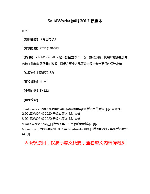
【期刊名称】《今日电子》
【年(卷),期】2011(000)011
【摘要】SolidWorks 2012是一款全面的313设计解决方案,使用户能够更加高效地工作和获取所需的数据,以便在整个产品开发过程中制定更好的设计决策。
【总页数】1页(P72-72)
【正文语种】中文
【中图分类】TH122
【相关文献】
1.SolidWorks 2014新功能小窥--链传动建模在新版本中的做法 [J], 席久恒
2.SOLIDWORKS 2020新版本概览 [J], 齐健
3.SOLIDWORKS 2020新版本概览 [J], 齐健
4.SolidWorks公司近日推出了其主打产品的最新版本 [J],
5.Cimatron公司应邀参加2014年Solidworks创新日活动暨2015年新版本发布会 [J],
因版权原因,仅展示原文概要,查看原文内容请购买。
Solidworks应用于电子产品设计的技术指南
Solidworks应用于电子产品设计的技术指南介绍:随着电子产品市场的不断扩大和创新,设计师们需要更高效、精确的工具来实现他们的创意。
Solidworks作为一款强大的计算机辅助设计软件(CAD),被广泛应用于电子产品设计领域。
本文将为设计师们提供Solidworks应用于电子产品设计的技术指南,帮助他们更好地利用这个工具来开发电子产品。
一、Solidworks基础知识在使用Solidworks进行电子产品设计之前,设计师需要熟悉软件的基本操作和功能。
以下是几个重要的基础知识:1. 零件建模:使用Solidworks的零件功能可以创建和修改三维模型。
通过使用零件建模工具,设计师可以创建电子产品的外观和内部结构,并进行各种加工操作。
2. 装配体设计:在Solidworks中,设计师可以将多个零件组合在一起,形成一个完整的装配体。
这种装配体设计可以帮助设计师更好地了解电子产品的组装方式,并进行必要的调整。
3. 二维绘图:通过使用Solidworks的二维绘图功能,设计师可以制作电子产品的工程图。
这些图纸可以被制造商用于生产和装配电子产品。
二、电子产品设计的实际应用在实际的电子产品设计中,Solidworks的应用非常广泛。
以下是一些常见的应用场景:1. 外壳设计:Solidworks可以帮助设计师创建电子产品的外壳结构。
设计师可以使用零件建模工具创建符合产品要求的外观,并为内部组件提供适当的空间。
2. PCB设计:Solidworks提供了专业的电路板设计工具,包括创建电子元件、布线和规划电路板布局的功能。
这些工具可以帮助设计师在产品设计的早期阶段确定电路板尺寸和形状。
3. 热管理:在设计电子产品时,热管理是一个重要的考虑因素。
Solidworks可以帮助设计师分析电子产品中的热量传递和散热问题,并提供优化解决方案。
4. 模拟仿真:Solidworks提供了强大的仿真功能,可以模拟电子产品在不同环境下的工作条件。
solidworks设计案例

Solidworks设计案例Solidworks是一款广泛应用于工程设计和制造的三维计算机辅助设计软件。
它具有强大的建模、渲染和分析功能,可以帮助工程师和设计师快速高效地完成设计任务。
在实际工程项目中,Solidworks已经成为了不可或缺的设计工具。
下面我们就来看看一些Solidworks设计案例,了解一下这个软件在实际工程项目中的应用。
1.汽车零部件设计汽车是现代人们日常出行的重要工具,而汽车零部件的设计对汽车的性能和质量起着至关重要的作用。
利用Solidworks软件,工程师可以对汽车零部件进行精确的三维建模和分析,确保其在使用过程中能够稳定可靠地运行。
可以通过Solidworks对发动机缸体进行流体动力学分析,优化其内部结构,提高燃烧效率和排放性能。
2.工业机械设计在工业生产中,机械设备的设计和制造是非常重要的环节。
利用Solidworks软件,工程师可以对各种工业机械进行全面的设计和分析。
可以通过Solidworks对数控机床进行动力学分析,优化其结构,提高工作精度和稳定性。
还可以结合Solidworks模拟机械零部件的运动,找出潜在的设计缺陷,提前进行改进,避免在实际生产中出现问题。
3.消费电子产品设计随着科技的发展,消费电子产品在人们的日常生活中扮演着越来越重要的角色。
利用Solidworks软件,设计师可以对各种消费电子产品进行精细的三维建模和渲染。
可以通过Solidworks设计手机外壳,实现精确的零件配合和表面贴图,确保产品外观美观大方。
另外,还可以利用Solidworks进行热仿真分析,确保电子产品在长时间使用过程中不会出现过热现象,保障产品的稳定性和耐用性。
4.建筑结构设计建筑结构是现代城市的重要组成部分,其安全稳定性直接影响到人们的生命财产安全。
利用Solidworks软件,工程师可以对各种建筑结构进行精确的三维建模和有限元分析。
可以通过Solidworks模拟建筑结构受力情况,找出潜在的薄弱环节,并进行针对性的加固设计,提高建筑结构的抗震抗风能力。
solidworks中国的可持续发展策略

社区建设
01
积极参与当地社区建设,推动社区发展,改善居民生活环境。
公益事业
02
支持教育事业、扶贫济困、灾害救助等公益事业,承担企业社
会责任。
志愿服务
03
鼓励员工参与志愿服务,提升员工社会责任感,树立企业良好
形象。
创新与研发
技术创新
不断投入研发资源,推动技术创新,提升企业核心竞争力。
人才培养
重视人才培养和引进,打造高素质研发团队,为企业可持续发展 提供强有力支持。
创造共享价值:通过与合作伙伴、员 工、客户等共同推动可持续发展,为 企业和社会创造共享价值。
提升品牌形象:积极履行社会责任, 关注环保与公益,有助于提升企业的 品牌形象和声誉。
综上所述,SolidWorks中国应积极 推动可持续发展策略的制定与实施, 以实现企业、社会和环境的和谐共生 。
03
SolidWorks中国可持续 发展策略核心领域
通过持续的技术创新和产品升级,推动行业进步 ,提高客户满意度。
绿色制造
优化生产流程,减少能源消耗和排放,实现绿色 、低碳的生产方式。
和谐共赢
与合作伙伴、员工、客户等利益相关者共同成长 ,实现多方共赢。
可持续发展策略对SolidWorks中国的重要性
适应市场变化:随着市场和客户需求 的变化,可持续发展策略有助于企业 及时调整自身发展方向。
行业协同
积极与同行业企业交流合作,分享经验和技术成 果,共同推动整个行业的可持续发展。
04
SolidWorks中国可持续 发展策略实施与成果
实施路径与方法
引入绿色设计理念
SolidWorks中国积极推行绿色设计,从产品设计初期即考虑环 境影响,减少资源消耗和环境污染。
SOLIDWORKS:预见未来的设计
SOLIDWORKS:预见未来的设计齐健【摘要】“今天的设计技术可以说还处在婴儿期,它的未来还会发生很多改变,并对我们的世界产生巨大的影响。
”在日前举办的SOLIDWORKS 2018中国发布会上,记者采访到了达索系统SOLIDWORKS首席执行官Gian Paolo Bassi,Gian Paolo 表示,未来的设计技术一定是以设计师为核心,以设计师的创新思想为核心的技术。
设计技术要能够帮助设计师抛开繁杂的案头工作,简化冗长的研发流程,快速地完成产品加工,简洁高效地把设计师的想法变成现实。
【期刊名称】《智能制造》【年(卷),期】2017(000)011【总页数】3页(P10-12)【关键词】SOLIDWORKS;设计师;首席执行官;记者采访;创新思想;产品加工;技术;婴儿期;【作者】齐健【作者单位】[1]不详;【正文语种】中文【中图分类】TP391.72“今天的设计技术可以说还处在婴儿期,它的未来还会发生很多改变,并对我们的世界产生巨大的影响。
”在日前举办的SOLIDWORKS 2018中国发布会上,记者采访到了达索系统SOLIDWORKS首席执行官Gian Paolo Bassi,Gian Paolo表示,未来的设计技术一定是以设计师为核心,以设计师的创新思想为核心的技术。
设计技术要能够帮助设计师抛开繁杂的案头工作,简化冗长的研发流程,快速地完成产品加工,简洁高效地把设计师的想法变成现实。
今天的SOLIDWORKS正在为这些需求不断努力创新,希望用最快的速度把未来的设计技术呈现在用户面前。
自动化的设计传统的计算机辅助设计只是帮助设计师展示他们的想法,并没有真正起到“辅助设计”的作用,计算机不能帮助设计者判断一个设计方案究竟好不好?好在哪?哪里还可以改进?即便是应用了仿真技术,也只是对设计结果进行验证,而无法判断这个设计结果是不是最优方案。
“自动化设计是SOLIDWORKS最重要的创新之一,我们希望能在产品设计的整个流程中实现自动化。
- 1、下载文档前请自行甄别文档内容的完整性,平台不提供额外的编辑、内容补充、找答案等附加服务。
- 2、"仅部分预览"的文档,不可在线预览部分如存在完整性等问题,可反馈申请退款(可完整预览的文档不适用该条件!)。
- 3、如文档侵犯您的权益,请联系客服反馈,我们会尽快为您处理(人工客服工作时间:9:00-18:30)。
SolidWorks创新日:设计无极限
作者:侯琳
来源:《CAD/CAM与制造业信息化》2013年第11期
2013年9月23日,一年一度的SolidWorks创新日在北京如期举办,达索系统SolidWorks 首席执行官Bertrand Sicot先生、达索系统专业渠道亚太区销售部副总裁吴俊杰先生、达索系统SolidWorks亚太区高级技术总监陈超祥先生以及达索系统SolidWorks大中国区技术总监胡其登先生出席了此次盛会。
创新日上,达索系统(Dassault Systèmes)正式推出了SolidWorks 2014 3D软件产品组合,涵盖了3D CAD、仿真、产品数据管理、技术沟通和电气设计,助力企业突破限制,实现更多创新设计。
本届创新日的主题是“设计无极限”,而大家可能都在思考,什么叫做设计无极限,陈超祥先生给出了自己的理解:“它是一个整合的工具系列,来帮助设计人员,完成更多的设计,可是所谓的设计无极限,不等于是天马行空。
”这就需要我们在进行一个工程设计时,要考虑到很多客观的问题,比如物理上能不能符合要求,以及产品的的成本和可制造性,所以此次Solidworks为工程师设计人员提供了“设计无极限”这个方向,一系列的整合工具使其在设计中可以有更多空间进行创新设计。
现在的Solidworks
Bertrand Sicot先生在演讲中特别强调了Solidworks对于用户的重视,他表示自3年前开始担任Solidworks CEO,就调整了工作重点:继续以用户为中心,继续了解用户的需求,不断地改进Solidworks解决方案,特别是软件的创新,使用户能够认可其创新价值;SolidWorks现有的用户社区非常庞大,全球大会有5 000多人,Solidworks将进一步投资社区的发展;移动应用;为用户研发PDM提供技术支持;为用户提供更高的附加值。
每年的SolidWorks都会发布新版本的产品,而2014新版本中除了3DCAD相关产品外,还有各类仿真产品:仿真的全线产品,能实现流体仿真、注塑仿真等,而此次还增加了可持续仿真。
同时,在产品设计完成后,必须要有企业级PDM的管理(包括流程图、内部流程审批等),另外用户还需要电气设计解决方案,而这一切,在SolidWorks 2014中均有体现。
用户最需要的改进功能
SolidWorks 2014是SolidWorks发布的第22个版本,其中包含了超过200个的新增功能和改进功能,大多数的新增功能都是直接来自客户的要求。
SolidWorks 2014提供了更加强大的设计功能、更有效的协作以及性能和效率的提高,可以使用户的设计更加快速,质量更高并且返工更少。
同时,其可以帮助用户集成更多的设计学科,与同事们的协作更容易,并且可以预
先验证产品的质量,并保持对成本的关注。
同时,不断改进的图形性能和多核处理为用户提供了真实的生产力并节省了时间。
用户可以通过SolidWorks的3D打印合作伙伴以物理原型的方式共享并获取对3D模型的早期支持。
借助eDrawings,企业可以通过iOS设备(如iPad或iPhone)上的增强现实
3DExperience查看3D设计,展示产品在现实世界中的反应。
集成的SolidWorks 2014产品组合包括用于缩短设计过程,强化协作并提高工作效率的全新工具和增强功能,涵盖4个方面:设计工具、一体化工作流程、提升性能及用于加强协作的增强可视化环境。
下面是用户最需要的改进功能,在SolidWorks 2014版本中均已实现。
1.设计工具
高级形状控制:全新的风格样条功能、自动化的草图图片自动配比缩放和圆锥过渡控制使得用户可以更快、更简单地创建复杂表面和形状,并对其进行精确的控制。
更快的详图设计:支持更快更自动化的详图设计。
钣金设计改进:全新的钣金设计功能,支持更快地创建钣金几何图形并改进数据输出用于生产。
用户可以通过边角处理和创建加强筋的功能更好地控制产品特性,比如安装支架上用于支撑部件承重和受力的缩进设计。
2.一体化工作流程
SolidWorks EPDM简化工作流程:通过与新版Microsoft Office的集成和带图像预览功能的增强型Web客户端更简便地管理更多的数据。
SolidWorks电气集成与性能的增强:强化与SolidWorks Electrical和eDrawings的集成使得用户通过更加简便地优化、共享并追溯电气设计改进项目协作。
3.性能提升
设计交流与协作:借助对Android设备的全新支持,移动用户可以在iOS设备之外扩展他们的浏览方式。
简化成本预算与报表:现在用户通过更少的设置即可更快地估算零件的制造成本,并以更高效的方式与其商业价值链共享成本数据。
比如,用于装配的关键产品开发数据现在可以导出到Microsoft Excel,更容易与制造和采购等其他部门共享数据。
4.增强的可视化环境
简化的仿真设置:SolidWorks Simulation自动将设计数据重用于模拟仿真,不仅避免重复工作同时加强了设计协作。
增强的装配性能和可视化:用户可以通过全新关联的快捷配合工具栏或槽口配合更快更简单地创建装配设计。
在装配的截面图中,用户可以添加或去除所选的部件,从而更快地创建更直观的截面图。