温度记录仪使用手册
ETCR电子科技有限公司 温度记录仪用户手册说明书
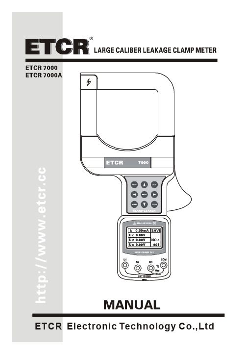
CONTENTWarning (1)Ⅰ.Introduction (2)Ⅱ. Model (2)Ⅲ. Electrical Symbols (3)Ⅳ. T echnical Specification (3)1.Switch On/Off (5)2.Backlight Control (5)3.Data Hold/Storage (5)4.Data Access/ Exit (6)6.Delete Data (6)7.Leakage Current/Current/V oltage Measurement (6)Ⅴ. Battery Replacement (8)Ⅵ. Accessories (9)WarningThank you for purchasing our ETCR7000 Large Caliber Leakage Clamp Meter, in order to better use of this product, be sure to:----To read this user manual carefully.----Comply strictly with safety rules and precautions set out in this manual.u Pay special attention to safety under any circumstances while using the instrument.u Take note of the label text and symbols on the panel and back of the instrument.u Keep the clamp clean and maintain regularly.u Please don’t place and store the instrument at the place with high temperature, humidity, moisture condensation and straight sunlight for a long time.u Replace battery in time when the battery voltage is low.u Remove or replace the battery if you expect not to use the instrument for a long time.u Take note of the polarity when replace the battery.u The operation, demolition, calibration and maintenance of the instrument must be carried out by qualified personnel authorized to do so.u The meter should be stopped from being used immediately and sealed if danger is brought up in case of continued use; only a competent body can be authorized to deal with it.u“” in the manual is the safety warning sign, the contents of this manual must be followed for safe operation.u” and other safety signs, the contents of this manual must be followed for safe operation.Ⅰ.IntroductionETCR7000 series of Large Caliber Leakage Clamp Meter is well designed and manufactured for measuring AC leakage current, current, voltage, adopt the latest CT technology and digital integrated technology. Its large caliber 80mm×80mm can clamp electric cable of 80mm diameter, or 96mm×4mm flat cable and steel earth wires. Full automatically and simultaneously measure one leakage current and three voltages, all the data are displayed in the screen, which is very clear and convenient. The meter is widely used in electric power, communication, meteorology, railway, oil field, architecture, measuring, teaching research unit, industrial mining enterprises, etc.ETCR7000 series of Large Caliber Leakage Clamp Meter’s clamp core is made of special alloy, adopt the latest magnetic shielding techniques, can almost shield the influence from external magnetic field, to ensure the high precision, high stability and high reliability of perennial uninterrupted measurement. The meter can store 200 sets of data, with RS232 interface, upload stored data to the computer through the system software, implementing online real-time monitoring, historical inquires, dynamic display. With the function of historical data read, preserve, print, and backlight, data hold, etc. It is a necessary tool for electrical safety testing.Ⅱ. ModelModel Measurement Range ResolutionDataStorageClampSizeAC0.00m~1200A 0.01mA ETCR7000 AC 0.00V~600V 0.01VAC0.0m~2000A 0.1mA ETCR7000A AC 0.00V~600V 0.01V 200sets80×80mmⅢ. Electrical SymbolsⅣ. Technical SpecificationFunction Measure AC leakage current, current, there-phase, voltagePower 6V DC(LR6×4 alkaline dry batteries, continuously working for 12 hours)Test Mode Clamp CT, integral modeClamp Size 80mm×80mm(can clamp electric cable of 80mm diameter, or 96mm×4mm flat cable and steel earth wires)0.00mA~300A: ±1.5%±3dgt300A~1200A: ±2%±3dgt1200A~2000A: ±3%±3dgtMeasurementAccuracy(23℃±3℃,below 70%RH,measured wireat the center ofthe clamp)0.00V~600V: ±1.5%±3dgtMeasured Wire Position Measured wire at approximately the geometric center of the clampData Storage 200 sets, “FULL” symbol indicate the memory is fullRS232 Interface With RS232 interface, download data to computer for analysis and managementCommunication RS232 communication wire, 1.8mWireFrequency 50Hz ,60Hz automatic identificationGear Shift Automatic shiftSample Rate About 2 times/secondLine Voltage Below AC 600V line measurementDisplay Mode LCD: 128dots×64dots; Display area: 43mm×29mm Meter Size Length 275mm × Width 145mm × Height 40mm Backlight Controlled by LIGHT keyData Hold “HOLD” symbol appearsOverflow “OL” symbol appearsAutomatic Shutdown Automatically shutdown about 15 minutes after power on to reduce battery consumptionVoltage Detection Low battery symbol “" appears to remind the replacement of battery when the battery voltage drops below 5.2V.Weight 1kg(with batteries and accessories)Working Current 50mA with enabled backlight; 25mA with disabled backlightWorkingTemperatureand Humidity-10℃~40℃; 80%rhStorageTemperatureand Humidity-10℃~60℃; below 70%rhInsulationstrengthAC 2kV/rms(between core and shell)Safety Specifications IEC1010-1, IEC1010-2-032, 2 class of pollution, CAT Ⅲ(600V)Ⅴ. Instrument Structure1. Clamp2. Function keys area3. LCD display4. Voltage input interface5. Opening lever6. RS232 interface7. Housing screw (6 pieces) 8. Battery cover9. Battery cover screw (1 piece)Ⅵ. Method of Operation1.Switch On/OffPress POWER key to switch on, LCD display, in test mode, press POWER key to switch off. The meter will automatically power off after booting 15 minutes later. If LCD display is darker, maybe the battery voltage is too low, please replace batteries.In data hold mode, firstly press HOLD key to cancel the lock, then press POWER key to switch off.2.Backlight ControlAfter booting, press LIGHT key to control the backlight, suitable for dim places and night, default open after booting.3.Data Hold/StorageIn test mode, press HOLD key to lock currently displayed value and display “HOLD“symbol. At the same time, this locked value as a set of datafollowed by auto-ID and store, display the group number such as “SAVE NO.:001”, and then press HOLD key to cancel the lock, “HD” symbol disappear, then continue to measure. Loop operation, the meter can store 200 sets of data. If the memory is full, display “FULL” symbol.4.Data Access/ ExitIn test mode, press MENU key to access data inquiry form group “R:001”, and display “READ”symbol. It is allowed to rapidly navigate to the desired page number. Press “△”key to increase the page number by one, press ”▽”key to increase the page number by ten. Press MENU key to exit date inquiry, back to test mode.5.Data UploadConnecting the meter and computer with USB-RS232 communication line attached in package. Start up the meter, run software, choose history access, then read, save, report, print history data, etc. The more data storage, take the longer time to read it. Historical data can be saved in Txt text or Excel format.6.Delete DataAt the date inquiry mode, press CLEAR key to access deleting data menu, then press“◁”or “▷” keys to move the cursor to “YES” or “NO” item. Press MENU key to confirm deletion or return to the test mode.7.Leakage Current/Current/Voltage MeasurementTest reference illustrations:GroundⅤ. Battery Replacement1.is displayed when the power voltage is lower than 5.2V, indicating that the battery should be replaced.2. Press POWER key, make sure the meter is power off. Loosen the batterycover screw, open the plate, replace new batteries and cover the plate, then tighten screw.3. Press POWER key to check whether the batteries are successfullyreplaced, repeat step 2 if it doesn’t work.Ⅵ. AccessoriesMain Unit 1 pieceMeter Box 1 pieceTest Line 4 pieces (3 red, 1 black) RS232 Data Line 1 pieceDisk 1 pieceBattery 4 pieces(Alkaline Dry Battery LR6)User Manual 1 pieceGuarantee Card 1 pieceCertification 1 piece。
JK500系列手持式多路温度记录仪用户手册说明书
声明根据国际版权法,未经常州金艾联电子科技有限公司(JinAiLian electronic Inc)事先允许和书面同意,不得以任何形式复制本文内容。
安全信息警告危险:为避免可能的电击和人身安全,请遵循以下指南进行操作。
免责声明用户在开始使用仪器前请仔细阅读以下安全信息,对于用户由于未遵守下列条款而造成的人身安全和财产损失,金艾联电子科技有限公司将不承担任何责任。
仪器接地为防止电击危险,请连接好电源地线。
不可在爆炸性气体环境使用仪器不可在易燃易爆气体、蒸汽或多灰尘的环境下使用仪器。
在此类环境使用任何电子设备,都是对人身安全的冒险。
不可打开仪器外壳非专业维护人员不可打开仪器外壳,以试图维修仪器。
仪器在关机后一段时间内仍存在未释放干净的电荷,这可能对人身造成电击危险。
不要超出本说明书指定的方式使用仪器超出范围,仪器所提供的保护措施将失效。
警告:不要加超过350V的直流电压或超过200V的交流电压到测试端,否则会损坏仪器。
安全标志:设备由双重绝缘或加强绝缘保护废弃电气和电子设备(WEEE)指令2002/96/EC切勿丢弃在垃圾桶内用户手册User’s GuideJK500系列手持式多路温度记录仪Handheld Multichannel Temperature Recorder有限担保和责任范围常州金艾联电子科技有限公司(以下简称JinAiLian)保证您购买的每一台JK500在质量和计量上都是完全合格的。
此项保证不包括保险丝以及因疏忽、误用、污染、意外或非正常状况使用造成的损坏。
本项保证仅适用于原购买者,并且不可转让。
自发货之日起,JinAiLian提供叁拾(30)天保换和贰年免费保修,此保证也包括VFD或LCD。
叁拾天保换期内由于使用者操作不当引起的损坏,保换条款终止。
贰年保修期内由于使用者操作不当而引起仪器损坏,维修费用由用户承担。
贰年后直到仪表终生,将以收费方式提供维修。
对于VFD或LCD的更换,其费用以当前成本价格收取。
温湿度记录仪操作说明书
温湿度记录仪操作说明书一、产品介绍温湿度记录仪是一种用于测量和记录环境温度和湿度的设备。
它适用于许多场所,包括仓库、实验室、办公室等,帮助用户监测和控制环境条件,确保工作和生活环境的舒适和安全。
二、操作步骤1. 开机与关机步骤:长按电源按钮,待显示屏亮起后松开按钮即可开机。
再次长按电源按钮,待显示屏关闭后即可关机。
2. 设置温湿度上限与下限步骤:进入菜单界面,通过方向控制键选择“设置”选项。
然后,进入“温湿度设置”子菜单,通过方向控制键分别设置温度和湿度的上、下限值。
完成设置后,按确认键保存。
3. 数据记录和导出步骤:在主界面选择“记录”,然后进入“开始记录”选项,即可开始温湿度的数据记录。
记录完成后,通过连接数据线将记录仪与电脑连接。
在电脑上打开数据导出软件,即可将记录仪内的数据导出为Excel或其他格式。
4. 数据分析和报表生成步骤:打开数据导出软件后,导入导出的数据文件。
利用软件提供的数据分析工具,可对温湿度数据进行统计、图表化分析。
点击“生成报表”按钮,可以生成详细的温湿度变化报表。
5. 温湿度校准步骤:进入菜单界面,选择“设置”选项,然后进入“温湿度校准”子菜单。
根据实际测量值和已知标准值,进行校准调整。
详细的校准步骤,请参阅产品附带的校准手册。
6. 电池更换步骤:当电池电量低于警示线时,屏幕将显示电池低电量提示。
此时应及时更换电池。
打开仪器背部的电池仓盖,将旧电池取出,并按照正确的极性方向装入新电池。
注意不要将电池弄湿。
7. 报警设置步骤:进入菜单界面,选择“设置”选项,然后进入“报警设置”子菜单。
根据需要,设置温湿度超过上下限时的报警方式和报警值。
三、注意事项1. 本设备仅限于测量和记录环境温度和湿度,不适用于其它用途。
2. 在使用本设备前,请仔细阅读说明书,并确保正确理解和掌握操作步骤。
3. 如需将记录仪连接到电脑,应使用产品附带的数据线,并在电脑端安装相应的导出软件。
4. 仪器在运输或长时间不使用时,应存放在干燥、通风、温度适宜的环境中。
YOKOGAWA温度记录仪中文说明书DR230130
简易操作手册DARWIN混合记录仪DR230目录1 DR230的基本操作 (2)1-2 构成系统(识别系统构成) (2)1-3 日期/时刻设定 (2)1-4 显示画面设定 (2)1-5 测试周期(SCAN)设定 (3)1-6 量程设定 (3)1-7 单位设定 (3)1-8 走纸速度设定 (3)1-10 记录开始/停止 (5)2 DR230 的应用操作 (6)2-1 区域(ZONE)记录设定 (6)2-2 TAG设定 (6)2-3 报警设定 (6)2-4 报表表头设定及打印 (7)2-5 报表打印 (7)2-6 手动打印 (7)2-7 A/D积分时间设定 (7)2-8 EVENT/ACTION功能设定 (8)2-9 测试数据保存 (8)2-10 设定参数保存 (10)2-11 调出设定参数 (11)2-12 运算设定 (11)2-13 调出测试数据 (12)1 DR230的基本操作1-1 电源ON接通主单元和子单元电源。
1-2 构成系统(识别系统构成)*DR231(独立型)无需此操作。
*DR232(扩展型)必须在使用之前进行此操作。
*每当发生过模块增减等系统构成变化时,必须在使用之前进行此操作。
按 键3秒以上。
按几次“”键,选择“RE-SYSTEM”。
按 键,进入构成系统确认画面。
按“”键,选择“YES”。
按 键,开始执行重组系统。
1-3 日期/时刻设定按 键。
按“”键,选择“CLOCK”。
按 键,进入时刻设定画面。
使用左右游标器选择位置,按“”/“”键选择数值,设定现在的时刻。
按 键,完成设定。
按 键,回到原来的画面。
1-4 显示画面设定按 键,屏幕出现“”标志,指向上段(MAIN)、中段(SUB1)或下段(SUB2)(下图)。
按 键,“”标志指向的画面变为交替显示AUTO、MAIN等菜单。
1-5 测试周期(SCAN)设定按住 键的同时接通电源开关,则进入基本设定状态(SETUP)。
按“”/“”键选择“SCAN_INTVL”。
Extech SD500 温湿度记录仪用户手册说明书

Manual del usuarioHigro-Termómetro Registrador Modelo SD500IntroducciónAgradecemos su compra del registrador de datos de temperatura/humedad SD500 de Extech. Este medidor mide, exhibe y guarda las lecturas de temperatura y humedad relativa. Los datos se guardan en una tarjeta SD para transferencia a la PC. Este medidor se embarca probado ycalibrado y con uso apropiado le proveerá muchos años de servicio confiableCaracterísticas∙La LCD simultáneamente presenta los indicadores de temperatura y humedad relativa∙Registrador de datos marca Fecha/Tiempo y guarda las lecturas en tarjeta SD en formato Excel® para fácil transferencia a una PC∙Enchufe para interfase RS-232 para PC∙Tasa de muestreo de datos elegible: 5, 10, 30, 60, 120, 300, 600 segundos∙Batería de larga duración o adaptador CADescripción del producto1. Indicador de humedad2. Indicador de temperatura3. Compartimiento lateral4. Botón LOG (Entrar)5. Botón SET6. Sensores7. Botón (HORA) ▲8.▼ botón 9. Enchufe adaptador CA10. Botón RESET (restablecer)11. RS-232 Salida 12. Ranura para tarjeta de memoria SDNota: El compartimiento de la batería y soporte inclinado se encuentran atrás del medidor.8OperaciónBatería Advertencia, Instalación y Reemplazo1. Cuando el icono aparece en pantalla indica que las baterías están débiles y se debenreemplazar. Sin embargo, aún se pueden tomar mediciones dentro de especificacionesdurante varias horas después de que aparece el indicador de batería débil y antes de que el instrumento pierda precisión.2. Para reemplace o instalar baterías, quite el tornillo cabeza Philips que asegura la tapa de labatería y quite la tapa.3. Reemplace las seis baterías AAA (use alcalinas para servicio pesado), observando lapolaridad4. Reemplace y asegure la tapa.Registrador1. Abra la tapa izquierda y inserte una tarjeta SD formateadaNota: La tarjeta SD debe ser de cuando menos 1GB de capacidadNota: No use tarjetas de memoria formateadas por otro medidor o cámara. Use elprocedimiento para formatear la tarjeta SD detallado en la sección de característicasavanzadas de este manual para formatear correctamente la tarjeta.Nota: El reloj interno debe estar ajustado a la hora correcta; vea la sección de características avanzadas de este manual para ajustar el reloj.Nota: La estructura de datos predeterminada usa el punto decimal “.” como indicador numérico decimal. Vea la sección de características avanzadas de este manual paracambiar a coma “,”.Nota: Si la tarjeta de memoria de SD no es instalada, "EMPTY" parecerá en la presentación Nota: Mensajes de error:2. Presione el botón LOGGER (registrador) durante >2 segundos para iniciar el registro. Enpantalla aparece “DATALOGGER” y el medidor pitará cada vez que registra datos (si elzumbador está activado).3. Para detener el registro, presione el botón LOGGER durante >2 segundos. “DATALOGGER”cambiará a “DATA” y el medidor hará una cuenta regresiva por los datos registrados.IMPORTANTE: Para evitar la corrupción de datos, no retire la tarjeta de memoria sin terminar correctamente la función registro.Verificación de Hora/Fecha/Tasa de muestreoPresione y sostenga el botón TIME (hora) durante >2 segundos y la pantalla alternará entre la fecha, hora y tasa de muestreo.Estructura de datos de la tarjeta SD1. Al insertar por vez primera la tarjeta SD en el registrador se crea la carpeta HTC01.2. La primera sesión del registrador creará un archivo HTC01001.XLS. Todos los datos seguardarán en este archivo hasta llegar a 30,000 columnas.3. Después de 30, 000 columnas, se creará un nuevo archivo HTC01002.XLS Esto se repitecada 30,000 columnas hasta HTC01099.XLS. En este punto se crea una carpeta nueva,HTC02 y se repite el proceso. HTC10 es la carpeta final.Transferencia de datos a una PC1. Quite la tarjeta de memoria del registrador de datos e inserte en la ranura para tarjeta SD de laPC.2. Ejecute Excel ® y abra el archivo de datos en la tarjeta de memoria dentro del programa dehoja de cálculo. El archivo se abre similar a la siguiente imagen.Configuraciones avanzadasLa función SET se usa para:∙Formatear la tarjeta de memoria SD∙Ajustar la fecha y hora∙Ajustar la tasa de muestreo∙Activar o desactivar el sonido del zumbador∙Ajustar el signo decimal de la tarjeta SD∙Seleccionar las unidades de temperatura∙Activar o desactivar la salida de datos vía RS2321. Presione y sostenga el botón SET durante 2 segundos para entrar al modo de configuración.En la pantalla aparecerá la primera función (Sd F). Presione el botón SET para explorar lassiete Funciones. Use los botones ▲ y ▼ para ajustar la función seleccionada. Use el botón“LOGGER" (registrador) para pasar por los campos dentro de una función. En modo SET, sino presiona algún botón dentro de 5 segundos el registrador regresará a modo normal.2. Sd F - Formatear la tarjeta SD. Pulse el botón ▲ para seleccionar sí o no. Sí, pulse el botónEnter. Cuando sí y Ent aparece, pulse la tecla Enter de nuevo para formatear la tarjeta yborrar todos los datos existentes. La pantalla mostrará un intermitente sí y ESC mientras quela memoria ha sido borrada y formateado.3. dAtE – Ajustar la fecha y hora. Presione los botones ▲ o ▼ para ajustar el camposeleccionado. Presione el botón Enter para guardar el valor y pasar por los distintos campos.4. SP-t – Ajuste la tasa de muestreo. Presione el botón ▲ para seleccionar la tasa de muestreo ypresione Enter para guardar la selección. Las opciones son: 5, 10, 30, 60, 120, 300, 600segundos y AUTO. En AUTO, se guardarán los datos cada vez que haya un cambio de >1%RH o >1°C/F5. bEEP - Ajuste el zumbador ON / OFF. Presione el botón ▲ para seleccionar ON / OFF ypresione Enter para guardar la selección.6. dEC - Ajuste el signo decimal de la tarjeta SD. Presione el botón ▲ para seleccionar USA(decimal) o Euro (coma) y presione Enter para guardar la selección.7. t-CF - Ajuste la unidad de temperatura a °F o °C y prensa Entra para almacenar la selección8. rS232 - Activar o desactivar la salida de datos vía RS232. Presione el botón ▲ paraseleccionar ON / OFF y presione Enter para guardar la selección9. ESC - Salir del modo configuración. Presione el botón SET para regresar a operación normal.Restablecimiento del sistema (RESET)Si se presenta una condición donde el CPU no responde al teclado o el medidor parececongelado, presione el botón RESET (restablecer) a un lado del registrador de datos (use un clip para papel o un objeto puntiagudo similar) para restablecer el medidor a un estado funcional. Interfaz RS232El medidor cuenta con un puerto serial para conexión al puerto serial de una PC. Llame a Soporte Técnico para más información sobre esta conexión.EspecificacionesPantalla LCD 60 mm x 50 mm (2.4 x 2.0”)Sensores de medición Temperatura: Sensor internoHumedad relativa: Tipo capacitancia de precisiónTarjeta de memoria Tarjeta de memoria SD, 1 GB a 16 GB.Tiempo de muestreo del registrador de datos 5/10/30/60/120/300/600 segundos o Auto. Compensación de temperatura AutomáticasegundoTasa de actualización del indicador Aprox.1Salida de datos RS 232Temperatura de operación0 a 50°C(32 a 122°F)Humedad de operación Menos de 90% HRFuente de energía Seis (6) baterías alcalinas AAA (UM4) o baterías para serviciopesado de 1.5 V o adaptador CA 9V.Vida de la batería Depende de la tasa de muestreo, para baterías alcalinas nuevas ytasa de muestreo de 60 segundos, > un mes es típico. Tasas demuestreo rápidas reducirán significativamente la vida de la batería.(0.62lbs)Peso 282gDimensiones 132 x 80 x 32 mm (5.2 x 3.1 x 1.3“)(RDG)PrecisiónEscala ResoluciónTemperatura00.0 a 50.0 °C 0.1°C ± 0.8°C32.0 a 122.0°F 0.1°F ± 1.5°FHumedad relativa70 a 90% 0.1% ± (4% de lectura + 1% HR)10 a 70% 0.1% ± 4% HRNota: Las pruebas de especificación anteriores fueron realizadas bajo un ambiente de intensidad de campo de RF menor a 3V/M y frecuencia menor a 30 MHz solamente.¡Usted, como el usuario final, es legalmente atado (ordenanza de Batería de UE) volvertodas las baterías utilizadas, la disposición en la basura de la casa es prohibida! ¡Puedeentregar sus baterías utilizadas/acumuladores en puntos de colección en su comunidado dondequiera baterías/acumuladores son vendidos!La disposición: Siga las estipulaciones legales válidas en el respeto de la disposición deldispositivo a fines de su ciclo vitalCopyright © 2013 FLIR Systems, inc.Reservados todos los derechos, incluyendo el derecho de reproducción total o parcial en cualquier medio.ISO-9001 Cert.。
上海搜博实业有限公司SR6100B-40温度记录仪产品使用手册说明书

SR6100B-40
RS485接口工业级4通道40点DS18B20温度记录仪
产品使用手册
文件版本: V23.8.21
SR6100B-40采用工业通用标准RS485总线 MODBUS-RTU协议接口,方便接入PLC,DCS等各种仪表或系统,用于监测温度等状态量。
内部使用了较高精度的传感内核及相关器件,确保产品具有较高的可靠性与卓越的长期稳定性, 可定制RS232、RS485、CAN、4-20mA、DC0~5V\10V、ZIGBEE、Lora、WIFI、GPRS、NB-IOT等多种输出方式。
技术参数
产品接线
请在断电线的情况下,按图示方法进行接线,如果产品本身无引线,线芯颜色供参考。
典型应用
应用方案
发货清单
RS485型:通讯协议
免责声明
本文档提供有关产品的所有信息,未授予任何知识产权的许可,未明示或暗示,以及禁止发言等其它方式授予任何知识产权的许可?除本产品的销售条款和条件声明的责任 , 其他问题公司概不承担责任。
并且,我公司对本产品的销售和使用不作任何明示或暗示的担保,包括对产品的特定用途适用性,适销性或对任何专利权,版权或其它知识产权的侵权责任等均不作担保,本公司可能随时对产品规格及产品描述做出修改,恕不另行通知。
联系我们
公司:上海搜博实业有限公司
地址:上海市宝山区南东路215号8幢
中文站:
国际站:
SKYPE : soobuu
邮箱:****************
电话: 86-021-******** / 66862055 / 66862075 / 66861077。
温度记录仪说明书
CONTENT PageI. SAFETY INFORMATION ----------------- 2 II. FEATURE ------------------------------------- 2 III. GENERAL SPECIFICATION -----------3 IV. NAME AND FUNCTION ------------------ 4 V. OPERATION INSTRUCTIONS:5.1 Setup Menu-----------------------------6 5.2 Measurement ------------------------10 5.3 Print ---------------------------------------12 5.4 Load Thermal Paper -----------------14 5.5 Replace Battery ---------------------15 VI. ATTENTION6.1 Cancel Timed Printing -------------16 6.2 Cancel Timed Recording -----------16 6.3 Master Reset -------------------------17 VII. Software7.1 Installation ---------------------------18 7.2 Introduction --------------------------19servicing not covered in this manual.3. Periodically wipe the case with a dry cloth. Do not use2. Text Print Out.3. The easy access menu buttons and text area in the LCDdisplay provide a simple and intuitive hierarchical menu operation for system setup.4. Built in system clock.5. Photo coupler isolated RS-232 interface.6. With Windows software.7. 32,000 Records Data Logger.8. T1 & T2 dual display with swapping display area.9. MAX / MIN function.10. REL function.2I. GENERAL SPECIFICATION1. Measurement Range: TYPE K -200¡C ~ 1370¡C -328¡F ~ 2498¡F TYPE J -200¡C ~ 760¡C -328¡F ~1400¡F2. Accuracy: -200¡C ~ 1370¡C –0.1% + 0.8¡C-328¡F ~ 2498¡F –0.1% + 1.6¡F3. Resolution: 0.1¡C / 0.1¡F4. Sample Rate: 2 times / second5. Input Protection: 60V DC or 24Vrms AC6. Data Logger: 32,000 Records7. Storage Condition: -10¡C ~ 60¡C (14¡F ~ 140¡F)0 ~ 80% RH8. Operating Condition: 0¡C ~ 50¡C (32¡F ~ 122¡F)0 ~ 80% RH9. Battery: Size AA 1.5V x 6 (alkaline battery)10. AC Adapter: DC 9V ~ 12V , 1A Min11. Thermal Paper: 58mm width, 31_12. Dimension: 242 x 98 x 42mm13. Weight: 580g Approx.14. Accessory: Tool BoxAlkaline Battery Size AA 1.5V x 6Instruction MenuK Type Sensor x 2 (-50¡C ~ 200¡C)Thermal Paper x 2 (31_x 58mm)RS-232 Connection CableWindows Software Disk34V. NAME AND FUNCTIONDC 9VT2T1T2¢X F RELPRINTINST RECFEEDMINMAX C¢X C T1TEMPERATURE RECORDEROPENMENUCMENUINSTPRINTFEEDREC REL MAX MIN¢X C ¢X F T1T2Paper SoltPaper Output Manual Feed Knob Print Head LevelL C DDC 9V JackSetup Panel Function PanelPrint PanelTemperature Sensor Input ConnectorFunction Panel:Setup Panel:Print Panel:Exit without savingEnterBrowse menu or number down Browse menu or number up Paper feed 2/3 inchStart / Stop printingPrint present data Power button¢X C / ¢X F button Record buttonT1 / T2 button Relative readout button MAX / MIN button6V. OPERATION INSTRUCTIONS5.1 Setup MenuPress Menu select button to select menuCMENU MENUTEMPERATURE RECORDEROPENExit without savingEnterBrowse menu or number down Browse menu or number up7Menu itemMenu description Set system clock Set thermocouple typeNote: Thermocouple type must be the same as thetype of sensor.369875421Set system clock Set start/stop printing time and print mode Set Thermocouple Typerecord interval Set start/stop recording time and Clear Datalogger memory Power management setup Alarm limit setupPrinter test printingPrint out setup information1Set time Set date Set year2Select J TypeSelect K Type16VII. Software7.1 InstallationSystem Required:Windows 95 / Windows 98 / Windows MEWindows NT 4.0.Minimum Hardware Required:PC with Pentium 90MHz or higher.32 MB RAM.4X CD-ROM Drive or higher.Recommended resolution 800X600.At least 5 MB byte hard disk space available toinstall TestLink.Installation :1.We recommend close all other applicationbefore installing TestLink.2.Insert the setup CD disc to CD-ROM drive and theinstallation program should start automatically.3.If installation do not start automatically, choose thestart button on the Taskbar and select Run.4.Type E:\SETUP and choose OK, then it will copySE500.exe (executable file) and help file to yourhard disk (default is c:\programfiles\TestLink\SE500).1819.2 IntroductionMain ScreenMain menuTool menuReading display Real time graphReal time list Max/Min/Avgdisplay Main ScreenFile : Open - Open files saved previously from the disk. Save - Save the active window(when the caption baris highlighted) data to the disk. Print - Print the data of the active window(graph or list).Printer Setup - Select printer.Exit - Terminates TestLink program.DataLogger : By opening the D ataLogger Window,the user can load recorded data ofmeter to PC in this window.Real Time Data : Run - Start recording real time data.Stop - Stop recording real time data.Option : Setup Temperature Recorder from PC. COM port : Select PC connector port manually.View : LCD - Open LCD simulation window.Real Time Graph - Open Real-Time Graphwindow to graph the presentdata.Window : Arrange windows Help : On line help.20DataLoggerata Sets ListData ListWhen you have Temperature Recorder meter connected to PC and select "DataLogger" from main menu or click from tool bar to load recorded data from the meter and there will be a progress indicator to show the loading progress. If error occurs, just click "D ataLogger" again.After the data was loaded completely, the top left hand side will show how many data sets were loaded and detail information for each data set (start data, start time,recording rate and record numbers).For examples, the figure below means there are two data sets, set 1 recorded 1325 records and set 2 recorded 19349 records.It will transfer first data set to graph on the right hand side and list data after loading, You can click other data set to view the graph and list of the data set you select.Tutorial Quick StartRecording real time data from PC.1.Power on the Temperature Recorder first and connect it to a PC RS-232 serial port wit the cable,2.Run the Software.3.If the connection is successful the LCD simulation willdisplay the same value as the Temperature Recorder.If fail to connect the meter with PC, it will display "NoConnection" on the LCD simulation window .4.When the connection is successful, select Real TimeData | Run from main menu or click from tool bar,there will be a dialog for you to select record intervaland record numbers and click start button to startrecording.5. When the recorded data numbers reach to theamount you set, it will stop recording, or click to stoprecording .How to save the recorded real time data to a file ?1.Click the window you want to save and the windowwill become active , then choose File | Save frommain menu or click from the tool bar.2.There will be a save dialog window for you to choosethe file name and file type to save.3.There are three types of file name you can choose,they are binary file(*.ghf), text file(*.txt) and EXCELformat file(*.csv). The *.ghf file use much fewer diskspace to save the data than the other two file format,but it can only be used in TestLink SE500. Text filecan be opened by TestLink SE500 and any otherword processor program like word, notepad etc.EXCEL format file can b e opened by TestLink SE500and Microsoft EXCEL.21How to load the recorded data from the memoryofTemperature Recorder and save it to a file ?1. Power on the Temperature Recorder.2. Connect the Temperature Recorder to PC3. Start SE500 program.4. Choose Data Logger from main menu or clickfrom tool bar.5. In reference to Data Logger, see [Page 20] aboutDataLogger.For more operation instruction, please refer to theonline help while executing SE500.22。
温度记录仪使用手册
目录一、概述 (1)二、功能特点 (2)三、技术指标 (4)四、安装与接线及外形结构 (6)五、仪表运行及操作 (10)六、仪表参数设置及通讯协议 (23)七、软件使用说明 (31)八、故障分析与排除 (35)一、概述触控数据记录仪以其丰富的显示画面、灵活的操作方式以及强大的记录、运算、控制和管理功能,在各行各业中获得了极其广泛的应用。
本产品吸纳了各种国内外数据记录仪的优点,应用最新的显示技术、微电子技术、数据存储和通讯技术,是一款功能齐全、操作方便、精确可靠、高性价比的产品。
本产品在配置方面拥有蓝屏和彩色屏两种选择。
可以接收多种类型的电流、电压和电阻信号,实现温度、湿度、压力、液面、流量、成分以及力、力矩、位移等物理量的显示、记录、越限监控、报表生成、数据通讯、信号变送以及流量累计等功能。
本产品主要由触控液晶屏、按键、ARM微处理器为核心的主板、主电源、外供变送器电源、智能通道板、大容量FLASH等构成:可配备不同类型的智能通道板,根据应用要求选择。
内置大容量FLASH,可通过U盘快速将FLASH中的数据转储到计算机中。
内置的FLASH的容量为70M字节,8通道时若20秒记录一次可记录108天,最快1秒记录一次所有通道的数据。
数字显示界面、棒图显示画面、实时曲线画面、追忆曲线画面追忆曲线读数光标功能。
测量、显示基本误差:±0.2% F·S可参数设置多点报警功能。
二、功能特点本产品显示信息量大、界面友好、操作简单,下面是主要功能特点:不需要笔和纸记录,日常维护工作量非常小,运行费用低;采用高亮度触控彩色TFT液晶屏,CCFL背光、画面清晰;采用ARM微处理器,可同时实现多路(仪器内部最高64路)信号采集、记录、显示和报警;采用70MB 大容量的FLASH 闪存芯片存贮历史数据,掉电永不丢失数据;全隔离万能输入,可同时输入多种信号,无需更换模块,直接在仪器上设置即可;显示工程量数据的数值范围更宽可显示6位数值:-999,99~1999.99;可以进行参数设置、显示工程位号,工程单位,有流量累积;具有闪动报警显示,同时指示各路通道的下下限、下限、上限、上上限报警;8路继电器报警输出(订做产品);显示精度高,基本误差为±0.2% F·S;内置GB2312汉字库,使用全拼输入法输入;支持外接微型打印机,手动打印数据、曲线,自动定时打印数据,满足用户现场打印的需求(订做产品);配备标准USB2.0接口。
虹润OHR-WS50系列大屏幕温湿度记录仪使用说明书
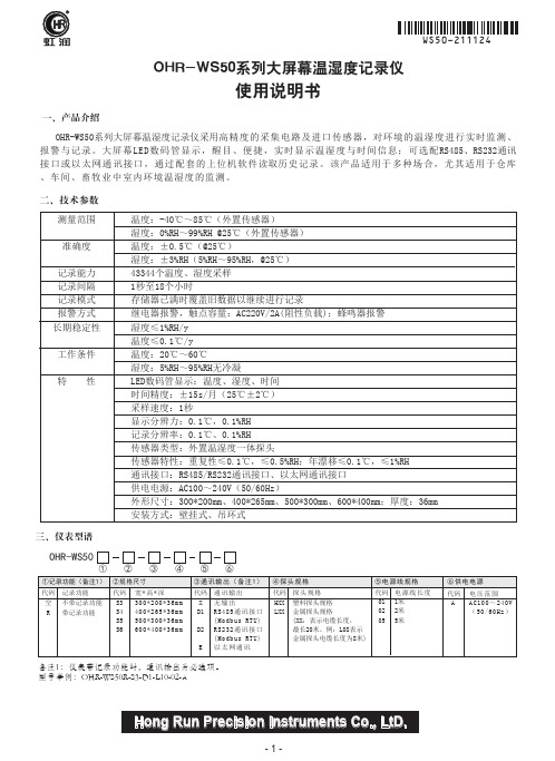
Hong Run Precision Instruments Co., LtD.虹润一、产品介绍使用说明书OHR-WS50系列大屏幕温湿度记录仪二、技术参数OHR-WS50系列大屏幕温湿度记录仪采用高精度的采集电路及进口传感器,对环境的温湿度进行实时监测、报警与记录。
大屏幕LED数码管显示,醒目、便捷,实时显示温湿度与时间信息;可选配RS485、RS232通讯接口或以太网通讯接口,通过配套的上位机软件读取历史记录。
该产品适用于多种场合,尤其适用于仓库、车间、畜牧业中室内环境温湿度的监测。
三、仪表型谱OHR-WS50代码S3S4S5S6宽*高*深300*200*36mm 400*265*36mm 500*300*36mm 600*400*36mm通讯输出无输出RS485通讯接口(Modbus RTU)RS232通讯接口(Modbus RTU)以太网通讯代码X D1D2E ②③④⑤④探头规格代码HXX LXX 探头规格塑料探头规格金属探头规格(XX:表示电缆长度,最长20米。
例:L08表示金属探头电缆长度为8米)③通讯输出(备注1)①②规格尺寸备注1:仪表带记录功能时,通讯输出为必选项。
型号举例:OHR-WS50R-S3-D1-L10-02-A电压范围AC100~240V (50/60Hz)⑥供电电源代码 A①记录功能(备注1)代码空R记录功能不带记录功能带记录功能⑤电源线规格代码010205电源线长度1米2米5米⑥测量范围准确度记录能力记录间隔记录模式报警方式长期稳定性工作条件特 性温度:-40℃~85℃(外置传感器)湿度:0%RH~99%RH @25℃(外置传感器)温度:±0.5℃(@25℃)湿度:±3%RH(5%RH~95%RH,@25℃)43344个温度、湿度采样1秒至18个小时存储器已满时覆盖旧数据以继续进行记录继电器报警,触点容量:AC220V/2A(阻性负载);蜂鸣器报警湿度≤1%RH/y 温度≤0.1℃/y 温度:20℃~60℃湿度:5%RH~95%RH无冷凝LED数码管显示:温度、湿度、时间时间精度:±15s/月(25℃±2℃)采样速度:1秒显示分辨力:0.1℃,0.1%RH 记录分辨率:0.1℃、0.1%RH传感器类型:外置温湿度一体探头传感器特性:重复性≤0.1℃,≤0.5%RH;年漂移≤0.1℃,≤1%RH 通讯接口:RS485/RS232通讯接口、以太网通讯接口供电电源:AC100~240V(50/60Hz)外形尺寸:300*200mm、400*265mm、500*300mm、600*400mm;厚度:36mm 安装方式:壁挂式、吊环式3) 操作按键:进入下一级菜单在参数设置时,进行参数修改后的确认,并进入下一级菜单在参数设置时,则作为移位键,在可修改的参数上循环移位选择/存储键后移键增加键减少键1)规格尺寸说明:显示窗口为高亮度LED显示。
温度记录仪使用说明书
温度记录仪使用说明书一、产品概述温度记录仪具备性能可靠、操作简单、功耗低、断电后数据不丢失、防水性能好等特点,数据处理软件界面友好。
该系列产品广泛适用于食品、药品、冷链运输及各个要求符合HACCP 体系的行业,也可用于实验室等需要对温度作监控记录的场所。
二、技术参数1、供电电源:2.4Ah 3.6V 非充电电池一枚(当温度记录仪与计算机有效连接时,其电源由计算机通过USB接口供给)2、测温范围:传感器外置状况下:-40.0℃~70.0℃3、测温精度:-20℃~20℃时±0.5℃;其余范围内±1℃4、温度分辨率:0.1℃5、记录周期:2秒~24小时可连续设置.6、传感器类型:NTC7、实时传输时间间隔:10秒至24小时可调8、记录容量:16000点。
9、工作环境要求:温度-30℃~50℃;湿度15%~85%10、数据输出:通过USB接口与计算机交换数据11、防护等级:IP65三、液晶屏状态说明Busy:忙状态,仪表重启经过此状态后进入正常工作状态:上限报警状态,当温度大于上限值显示此报警状态:下限报警状态,当温度小于下限值显示此报警状态Wait:记录未启动状态,可持续按键5秒启动记录Record:处于记录状态End:记录停止状态Max:已记录数据的最大值Min:已记录数据的最小值Act:当前数据Log:历史数据(最大值、最小值、已记录容量)EE:传感器故障状态℃:温度单位:电池容量四、主要功能该仪表可对记录仪属性进行设置,包括用户信息、仪表站号、报警上下限参数;工作状态指示;单键操作,状态指示灯可指示各工作状态、可启动记录、可选择停止记录;符合HACCP的要求;温度传感器可内置亦可外置(出厂配置为外置传感器)。
可设置记录间隔、温度报警的上下限、记录仪时钟及记录仪和用户信息等属性,数据软件还具有数据分析的功能,可通过列表显示数据和绘制曲线分析图,对超温限报警点显示报警标志。
历史数据可以查询、保存、打印和以Word格式输出。
S100 温湿度记录仪使用说明手册说明书
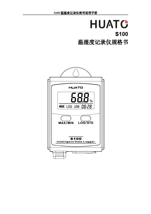
S100温湿度记录仪规格书目录第一章产品介绍 (1)1.1介绍 (1)1.2特性 (1)1.3应用环境 (1)1.4记录仪数据 (2)1.5温湿度记录仪S100-ET/S100-EX外观 (2)1.6温湿度记录仪S100-T/S100-TH外观 (3)1.7S100系列温度记录仪显示屏 (3)1.8S100系列温湿度记录仪显示屏 (4)1.9按键功能介绍 (4)1.10设备状态说明 (4)第二章软件使用指南 (7)2.1计算机硬件的要求 (7)2.2USB驱动安装 (7)2.3LogPro软件使用 (9)2.3.1读取和设置记录仪属性 (9)2.3.2参数设置说明 (10)2.3.3查看数据 (10)2.3.4删除数据 (11)3.1液晶屏显示暗淡 (12)3.2日期&时间错误 (12)3.3软件运行错误 (12)第一章产品介绍1.1介绍华图S100系列记录仪是华图公司最新推出的用于疫苗、冷藏运输、低温冷库等场所的具有国内领先水平的温度测量仪器,采用原装进口之温湿度传感器,精度高,一致性非常好,两节1.5V7号电池供电,连续工作时间达6个月以上,是国家技术监督总局认可的计量仪器。
1.2特性(1)外形小巧精致,使用方便;(2)传感器由瑞士生产,精度高;(3)2节1.5V7号电池可以工作6个月以上,25℃环境(采样间隔60秒,记录间隔300秒);(4)主机尺寸:57x92x20mm;(5)LCD屏幕尺寸:37x17mm;(6)温度和湿度外探针直径:16mm;(7)温度外探头直径:6mm;1.3应用环境(1)疫苗(2)冷藏运输(3)低温冷库(4)工作及生活区域(5)超市1.4记录仪数据1.5温湿度记录仪S100-ET/S100-EX外观LCD显示区型号标签LOG/STD:记录和开关机按键电池盖,打开可更换电池MIN/MIN:最大最小值查看按键USB接口外置传感器接口外置温湿度传感器(S100-EX/S100-EX+)挂孔外置温度传感器(S100-ET/S100-ET+)1.6温湿度记录仪S100-T/S100-TH外观LCD显示屏挂孔LOG/STD按键型号标签MAX/MIN按键电池盖传感器USB端口1.7S100系列温度记录仪显示屏温湿度数值显示区域USB连接标志记录过程中的最大值显示年-月日-时分切换显示记录过程中的最小值华氏度单位符号电池电量摄氏度单位符号记录状态标志1.8S100系列温湿度记录仪显示屏温湿度数值显示区域USB连接标志记录过程中的最大值显示年-月日-时分切换显示记录过程中的最小值湿度单位符号电池电量华氏度单位符号记录状态标志摄氏度单位符号1.9按键功能介绍:进行当前值与记录过程中的最大值、最小值切换(数值锁定);:设备关机时,长按5S后开机进入待机模式,再按3S进入记录模式;记录模式下,按3S可进入待机模式(仅进入待机模式),在待机模式下,按5S 关闭设备。
TempaChek-DL 温度数据记录仪说明书
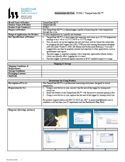
Instructions for Use: TCDL2: TempaChek-DL™Brand Name of Product TempaChek-DL™Generic Name of Product TempaChek-DLProduct Code Number(s)TCDL2Purpose of Product The TempaChek-DL™ is a thermologger capable of measuring the water temperaturethrough the cycle.Range of Applications for Product To track temperature in a specific environment.Key Specifications of Product∙TempaChek-DL™ is a data logger that measures and stores up to 32,510 temperaturereadings over a -40 to +125°C (-40°F to +257°F) range.∙You can easily set up the logging rate and start-time, and download the stored databy plugging the data logger into a PC's USB port and running the purpose designedsoftware under Windows 2000, XP (Home and Professional Editions), Vista and 7.Logged data can then be graphed, printed and exported to other applications such asspreadsheets and reports.∙The data logger is supplied complete with a long-life, replaceable lithium battery,which can typically allow logging for two years.∙The data logger is protected against moisture to IP 67 standard using two o-rings.123456789 1012 131415 161718 192020aSteps for Use of Product 1.Insert software flash drive into USB port on your computer.2.Select “Open folder to view files”.3.Next select folder “Temp-DL”.4.Then select the icon that reads, “Set up Temp DL”.5.Install window will be prompt open, click “Install”.6.Then click “Next”.7.When installation is finished, select “Finished” when window is prompted open.8.Unscrew cap of the TempaChek-DL™ Datalogger.9.Insert the TempaChek-DL into a free USB port on your computer.10.The computer will automatically detect the presence of the TempaChek-DL™ andstart the hardware installation process.11.Double-click the EasyLog USB icon on your desktop to launch the control software.You will be presented with three options on the Main Screen.12.Click on the green button to set up and start the TempaChek-DL™ Data Logger andfollow the setup procedure:B Data Logger Name, Temperature Scale and Sample Rate: - enter the LoggerName, - select the Temperature Scale, - select the Sample Rate, - then click “Next”.a.Note: If you are using this Data Logger for the first time, then it maycontain some sample data, in which case you will receive a warningmessage. Click “OK” to continue.14.Logger Options: - select whether the logger should stop saving data when full orbegin overwriting the oldest data. Then click “Next”.15.Setting alarm levels for the USB Data Logger: - select the Alarms, if required, -select the Alarm Trigger Levels for any selected alarms, - select Hold for anyselected alarms, - then click “Next”.16.Setting the start time and date: - either click Finish if you want to start loggingimmediately or - select the Start Time and Start Date for logging to commence, andthen click “Finish”. The summary screen will now appear.17.Remove the TempaChek-DL™ from the computer and place it in the location whereyou want to measure temperature.a.Note: If you leave the TempaChek-DL™ connected to your PC, the DataLogger will operate at an elevated temperature, due to a self-heating effect.This will cause the Data Logger to record erroneous temperature readings.If the Data Logger is connected to the USB port for a long time (e.g. 15minutes), then you should allow time for the Data Logger to cool down afterdisconnecting it from the USB port.18.Click on the “red” button to stop the datalogger and download and stored data.a.You will be asked to confirm that you wish to stop the USB Data logger,click “yes”.19.A window will pop up to show that the Data Logger has stopped. It will also displaythe name and amount of readings stored.20.Save the file under a suitable file name.a.The data will remain in the logger’s memory until it has been set up again. Interpretation of ResultsContraindications of Test ResultsDocumentationSpecial Warnings and Cautions∙When the TempaChek-DL™ is connected to the USB port, the battery inside theData Logger is discharged at a higher rate than normal. To conserve battery life, donot leave the TempaChek-DL™ connected to the USB port for a prolonged period oftime.∙The TempaChek-DL™ is a professional measuring instrument, designed to recordTEMPERATURE. Care must be taken when:o 1. Removing the logger from extreme environment- The logger is metal andwill retain heat or will remain cold when it has been removed from theenvironment under measurement. Personal protection, such as suitable heatresistant gloves or tools must be used to remove the logger from anyenvironment. See data sheet for maximum and minimum temperatures thatthe logger can be used in.o 2. Replacing batteries- Always operate TempaChek-DL™ and replace itsbatteries according to the instructions.∙The TempaChek-DL™ will work in extreme temperatures. However, many batterieswill not work at these extremes. Always ensure the specific battery as detailed byHealthmark is used. Serious injury can occur if the incorrect battery is used.∙TempaChek-DL™ is not authorized for use as a critical component in life supportdevices or systems.DisposalRelated Healthmark ProductsOther Product Support Documents For more information go to “Help” file contents on the software installation flash drive. Reference Documents ProFormance™ Brochure, ProFormance™ Price ListCustomer Service Contact Healthmark Industries Company, Inc.18600 Malyn Blvd.Fraser, MI 480261-586-774-7600********************。
HOBO MX100 温度计记录仪用户手册说明书
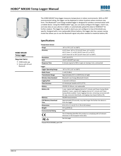
HOBO® MX100 Temp Logger ManualThe HOBO MX100 Temp logger measures temperature in indoor environments. With an IP67environmental rating, the logger can be deployed in indoor locations where moisture mayform. This Bluetooth® Low Energy-enabled logger is designed for wireless communication witha mobile device. Using the HOBOmobile® app, you can easily configure the logger, read it out,and view data on your phone or tablet, or automatically upload the data to HOBOlink® forfurther analysis. The logger has a built-in alarm you can configure to trip at thresholds youspecify. Designed with a non-replaceable lithium battery, this logger also has a power-savingmode that allows you to use the Bluetooth signal only when needed to maximize battery life.SpecificationsTemperature SensorRange -30° to 70°C (-22° to 158°F)Accuracy ±1.0°C from -30° to -5°C (±1.8°F from -22° to 23°F)±0.5°C from -5° to 50°C (±0.9°F from 23° to 122°F)±1.0°C from 50° to 70°C (±1.8°F from 122° to 158°F)Resolution 0.04°C (0.072°F)Drift <0.01°C (0.018°F) per yearResponse Time 6 minutes typical to 90% in open air moving 1 m/s, unmountedLoggerLogger Operating Range -30° to 70°C (-22° to 158°F)Radio Power 1 mW (0 dBm)Transmission Range Approximately 30.5 m (100 ft) line-of-sightWireless Data Standard Bluetooth Low Energy (Bluetooth Smart)Logging Rate 1 second to 18 hoursTime Accuracy ±1 minute per month at 25°C (77°F)Battery CR2450 3V lithium, not replaceableBattery Life 1 year, typical with logging interval of 1 minute and Power Saving Modedisabled; 2 years, typical with logging interval of 1 minute and PowerSaving Mode enabled. Faster logging intervals, remaining connected withthe app, excessive downloads, and paging may impact battery life.Memory 30,000 measurementsFull Memory Download Time Approximately 30 seconds; may take longer the farther the device is from the loggerDimensions 6.9 x 4.5 x 1.1 cm (2.71 x 1.76 x 0.42 inches)Weight 25.5 g (0.90 oz)Environmental Rating IP67The CE Marking identifies this product as complying with all relevantdirectives in the European Union (EU).See last pagePassed RTCA DO160G, part 21HLogger Components and OperationMounting Loop: Use this when deploying the logger by tying it to an object.Alarm LED: This LED blinks red every 4 seconds when an alarm is tripped (unless Show LED is disabled as described inConfiguring the Logger ). Both this LED and the status LED will blink once when you press the start button to wake up thelogger before configuring it. If you select Page Logger LED in the HOBOmobile app, both LEDs will be illuminated for 4 seconds. Status LED: This LED blinks green every 4 seconds when the logger is logging (unless Show LED is disabled as described in Configuring the Logger ). If the logger is waiting to start logging because it was configured to start “On button push” or with a delayed start, it will blink green every 8 seconds.Start Button: Press this button for 1 second to wake up the logger; both the alarm and status LEDs will blink. Once thelogger is awake, press this button for 1 second to move it to the top of the loggers list in HOBOmobile. Press this button for 4 seconds to start or stop the logger when it is configured to start or stop “O n button push” (see Configuring the Logger ). Both LEDs will blink four times when you press the button to start or stop logging. Press this button for 10 seconds to reset a password.Downloading HOBOmobile and Connecting to a LoggerInstall the HOBOmobile app to connect to and work with the logger.1. Download the HOBOmobile app from the App Store®.2. Press the button on the logger to wake it up.3. Open the app and enable Bluetooth in the device settings ifprompted. 4. Tap the HOBOs icon at the bottom of the screen. Tap thelogger in the list to connect to it.If the logger does not appear in the list or if it is having trouble connecting, follow these tips.∙ Make sure the logger is “awake” by pressing the start button. The alarm and status LEDs will blink once when the logger wakes up. You can also press the button asecond time to bring it to the top of the list if you are working with multiple loggers.∙ Make sure the logger is within range of your mobiledevice. The range for successful wireless communication is approximately 30.5 m (100 ft) with full line-of-sight.∙ If your device can connect to the logger intermittently or loses its connection, move closer to the logger, within sight if possible. ∙ If the logger appears in the list, but you cannot connect to it, close HOBOmobile and power cycle the mobile device. This forces the previous Bluetooth connection to close.Once the logger is connected, you can select one of the following actions:∙ Configure. Select logger settings and load them onto the logger to start logging. See Configuring the Logger . ∙ Readout. Download logger data. See Reading Out the Logger .∙ Full Status Details. Check the battery level and view the configuration settings currently selected for the logger. ∙ Start Logging. Select this option to begin logging (if the logger is configured to start “On Button Push” as described in Configuring the Logger ). ∙ Stop Logging. Stop the logger from recording data. This overrides any other Stop Logging settings that may be configured. ∙ Page Logger LED. Press and hold this option to illuminate the alarm and status LEDs for 4 seconds. ∙ Logger Password. Select this to create a password for the logger that will be required if another mobile device attempts to connect to it. To reset a password, connect to the logger, tap Set Logger Passkey, and select Reset to Factory Default. You can also press the button on the logger for 10 seconds to reset the password. ∙ Update Firmware. When new logger firmware is available, this action appears in the list. Select it andfollow the instructions on the screen. Note that if there is a communication failure during the firmware update process, the logger will revert to the previous firmware.∙ Force Offload. This may appear if an error wasencountered when loading configure settings. Select this to offload all the data on the logger before reconfiguring the logger.Alarm LED Status LEDMounting LoopStart ButtonConfiguring the LoggerUse HOBOmobile to set up the logger, including selecting the logging interval, start and stop logging options, configuring alarms, and enabling Power Saving Mode.1.Press the button on the logger to wake it up.2.Find the logger in the list and tap it to connect to it. If youare working with multiple loggers, you can press the button on the logger a second time to bring it to the top of the list.The logger name (or serial number if no name has beenassigned) turns green when the logger moves to the top of the list. Note that the current temperature is displayedeven when the logger is not logging.3.Once connected, tap Configure.4.Tap Name and type a name for the logger up to 20characters (optional). Tap Done. If no name is selected, the logger serial number is used as the name.5.Tap Group to add the logger to the Favorites group, anexisting custom group, or create a new group name up to20 characters (optional). Tap Done.6.Tap Logging Interval and choose how frequently the loggerwill record data.7.Tap Start Logging and select when logging will begin:∙Now. Logging will begin immediately after tapping Startin the Configure screen.∙On Next Logging Interval. Logging will begin at the nexteven interval as determined by the selected logginginterval.∙On Button Push. Logging will begin once you press thebutton on the logger for 4 seconds.∙On Date/Time. Logging will begin at a date and time youspecify. Select the Date and time and tap Done.Tap Done in the Start Logging screen. 8.Tap Stop Logging and select the options for when loggingwill end.a.Choose one of two memory options:∙When Memory Fills. The logger will continue recordingdata until the memory is full.∙Never (Wrap When Full). The logger will continuerecording data indefinitely, with newest dataoverwriting the oldest.b.Select On Button Push if you want to be able to stoplogging by pushing the button on the logger for 4seconds. Note that if you also choose On Button Push forthe Start Logging option, then you will not be able to stop logging until 30 seconds after logging begins.c.Select one of the following time options for when to stoplogging:∙Never. Select this if you do not want the logger to stopat any predetermined time frame.∙On Date/Time. Select this if you want the logger tostop logging on a specific date and time. Select thedate and time and then tap Done.∙After. Select this if you want to control how long thelogger should continue logging once it starts. Choosethe amount of time you want the logger to log dataand then tap Done. For example, select 30 days if youwant the logger to log data for 30 days after loggingbegins.d.Tap Done in the Stop Logging screen.9.Tap the Temperature sensor to configure alarms (optional).a.Enable the High Alarm if you want an alarm to trip whenthe sensor reading rises above the high alarm value. Dragthe slider to the reading that will trip the alarm or tap the value field and type a specific reading. In this example, an alarm will trip when the temperature rises above 85°F.b.Enable the Low Alarm if you want an alarm to trip whenthe sensor reading falls below the low alarm value. Dragthe slider to the reading that will trip the alarm or tap the value field and type a specific reading. In the example, analarm is configured to trip when the temperature fallsbelow 32°F. Note:The actual values for the high and lowalarm limits are set to the closest value supported by thelogger.c.Under Raise Alarm After, select the duration before analarm is tripped and tap Done in the Alarm Duration.d.Select either Cumulative or Consecutive Samples. If youselect Cumulative Samples, then the alarm will trip whenthe time the sensor is out of range over the course of thedeployment is equal to the selected duration. If youselect Consecutive Samples, then the alarm will trip when the time the sensor is continuously out of range is equalto the selected duration. For example, the high alarm fortemperature is set to 85°F and the duration is set to 30minutes. If Cumulative is selected, then an alarm will triponce a sensor reading has been at or above 85°F for atotal of 30 minutes since the logger was configured;specifically, this could be 15 minutes above 85°F in themorning and then 15 minutes above 85°F again in theafternoon. If Consecutive is selected, then an alarm willtrip only if all sensor readings are 85°F or above for acontinuous 30-minute period.e.Tap Done in the Temperature Alarms screen. Back in theConfigure screen, a setting to maintain the alarm untilthe logger is reconfigured is enabled automatically. Thiscannot be disabled.10.Enable or disable Show LED. If Show LED is disabled, thealarm and status LEDs on the logger will not be illuminated while logging (the alarm LED will not blink if an alarm trips).You can temporarily turn on LEDs when Show LED isdisabled by pressing the button on the logger for 1 second.11.Enable or disable Power Saving Mode. If Power SavingMode is disabled, the logger will “advertise” or regularlysend out a Bluetooth signal for the phone or tablet to find via HOBOmobile while it is logging, which uses batterypower. When Power Saving Mode is enabled, the logger will only advertise during logging when you press the button on the logger to wake it up, thereby preserving as muchbattery power as possible.12.Tap Start in the upper right corner of the Configure screento load the settings onto the logger.Logging will begin based on the settings you selected. See Deploying the Logger for details on mounting and see Reading Out the Logger for details on downloading.If the logger was configured with alarm settings, an alarm will trip when the temperature reading is outside the range specified in the logger configuration. When an alarm trips, the logger alarm LED blinks every 4 seconds (unless Show LED is disabled), an alarm icon appears in the app, and an Alarm Out of Range event is logged. Even if the temperature reading returns to a normal range, the alarm indicator will not clear in the app and the alarm LED will continue to blink. Setting a PasswordYou can create an encrypted password for the logger that will be required if another phone or tablet attempts to connect to it. This is recommended to ensure that a deployed logger is not mistakenly stopped or purposely altered by others. This password uses a proprietary encryption algorithm that changes with every connection.To set a password:1.Tap the HOBOs icon and connect to the logger.2.Tap Logger Password.3.Type a password up to 10 characters.4.Tap Save.Only the phone or tablet used to set the password can then connect to the logger without entering a password; all other mobile devices will be required to enter the password. For example, if you set the password for the logger with your tablet and then try to connect to the device later with your phone, you will be required to enter the password on the phone but not with your tablet. Similarly, if others attempt to connect to the logger with different devices, then they would also be required to enter the password. To reset a password, connect to the logger, tap Set Logger Passkey, and select Reset to Factory Default or press the button on the logger for 10 seconds.Reading Out the LoggerTo download data from the logger:1.Tap the HOBOs icon and tap the logger to connect to it. Ifthe logger was configured with Power Saving Modeenabled, press the button on the logger to wake it up.When working with multiple loggers, you can also press the button on the logger to bring it to the top of the list.2.Once connected, tap Readout.3.Tap the Data Files icon to view a mini-graph of thedownloaded data.4.Tap the mini-graph to view a larger version of the graph orto share the file. See the HOBOmobile User’s Guide fordetails on viewing graphs and sharing data.Data can also be uploaded automatically to HOBOlink, Onset’s web-based software. Tap the Settings icon to enable the HOBOlink Upload Data option (this requires a HOBOlink account at ). See the HOBOmobile User’s Guide for more details on this setting and see the HOBOlink help for details on working with data in HOBOlink.Logger EventsThe logger records the following events to track logger operation and status. To plot events in HOBOmobile, tap a mini-graph and then tap . Select the events you wish to plot and then tap again. You can also view events in shared or exported data files.Event Name DefinitionHost Connect The logger was connected to a mobiledevice.© 2016 Onset Computer Corporation. All rights reserved. Onset, HOBO, HOBOmobile, and HOBOlink are registered trademarks of Onset Computer Corporation. App Store is a service mark of Apple Inc. Bluetooth and Bluetooth Smart is a registered trademark of Bluetooth SIG, Inc. All other trademarks are the property of their Event Name DefinitionStarted The logger started logging. Stopped The logger stopped logging.Alarm Out of Range/In RangeAn alarm has occurred because the reading was outside the alarm limits or back within range. Note: Although the reading may return to a normal range, the alarmindicator will not clear in the app and the alarm LED will continue to blink until you reconfigure the logger.Safe ShutdownThe battery level dropped below a safe operating voltage and performed a safe shutdown.Deploying the LoggerYou can deploy the logger by using tape or the mounting loop.∙ On the back of the logger, remove the backing on the tape that is adhered to the top and bottom of the logger and mount it on a flat surface. ∙ Use the mounting loop to tie the logger to another object. The logger can be placed in indoor locations that experience condensation. Although the logger can withstand incidental splashing with water, do not deploy it in a permanently wet location.Protecting the LoggerNote: Static electricity may cause the logger to stop logging. The logger has been tested to 8 KV, but avoid electrostaticdischarge by grounding yourself to protect the logger. For more information, search for “static discharge” on .Battery InformationThe logger uses one CR2450 non-replaceable lithium battery. Battery life is 1 year, typical with a logging interval of 1 minute, but may be extended to two years when the logger isconfigured with Power Saving Mode enabled. Expected battery life varies based on the ambient temperature where the logger is deployed and the frequency of connections, downloads, and paging. Deployments in extremely cold or hot temperatures or a logging interval faster than 1 minute can impact battery life. Estimates are not guaranteed due to uncertainties in initial battery conditions and operating environment.WARNING: Do not cut open, incinerate, heat above 85°C (185°F), or recharge the lithium battery. The battery mayexplode if the logger is exposed to extreme heat or conditions that could damage or destroy the battery case. Do not dispose of the logger or battery in fire. Do not expose the contents of the battery to water. Dispose of the battery according to local regulations for lithium batteries.Federal Communication Commission Interference StatementThis equipment has been tested and found to comply with the limits for a Class B digital device, pursuant to Part 15 of the FCC Rules. These limits are designed to providereasonable protection against harmful interference in a residential installation. This equipment generates uses and can radiate radio frequency energy and, if not installed and used in accordance with the instructions, may cause harmful interference to radio communications. However, there is no guarantee that interference will not occur in aparticular installation. If this equipment does cause harmful interference to radio or television reception, which can be determined by turning the equipment off and on, the user is encouraged to try to correct the interference by one of the following measures: ∙ Reorient or relocate the receiving antenna∙ Increase the separation between the equipment and receiver∙ Connect the equipment into an outlet on a circuit different from that to which the receiver is connected ∙ Consult the dealer or an experienced radio/TV technician for helpThis device complies with Part 15 of the FCC Rules. Operation is subject to the following two conditions: (1) This device may not cause harmful interference, and (2) this device must accept any interference received, including interference that may cause undesired operation.FCC Caution: Any changes or modifications not expressly approved by the party responsible for compliance could void the user's authority to operate this equipment. Industry Canada StatementsThis device complies with Industry Canada license-exempt RSS standard(s). Operation is subject to the following two conditions: (1) this device may not cause interference, and (2) this device must accept any interference, including interference that may cause undesired operation of the device. Avis de conformité pour l’Industrie CanadaLe présent appareil est conforme aux CNR d'Industrie Canada applicables aux appareils radio exempts de licence. L'exploitation est autorisée aux deux conditions suivantes : (1) l'appareil ne doit pas produire de brouillage, et (2) l'appareil doit accepter tout brouillage radioélectrique subi, même si le brouillage est susceptible d'en compromettre le fonctionnement.To comply with FCC and Industry Canada RF radiation exposure limits for general population, the logger must be installed to provide a separation distance of at least 20cm from all persons and must not be co-located or operating in conjunction with any other antenna or transmitter.。
海康威视 HC-2000 温度记录仪说明书
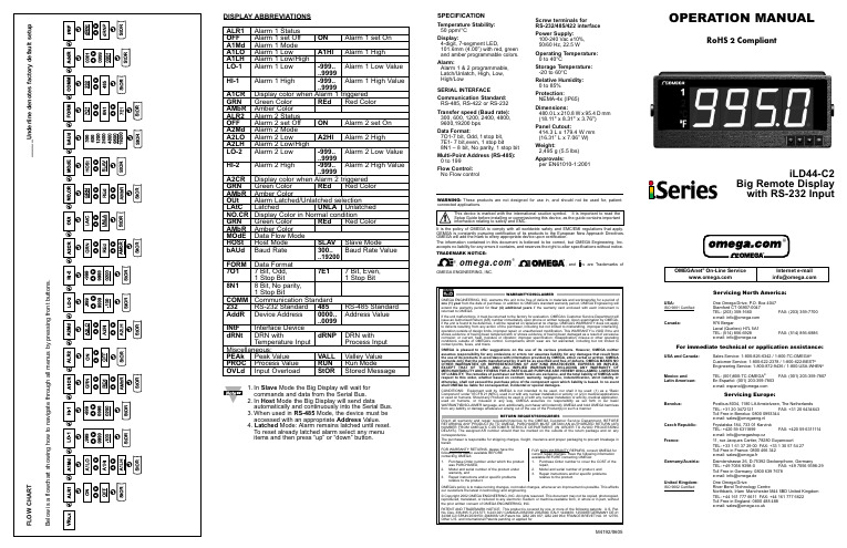
SPECIFICATIONTemperature Stability:50 ppm/°C Display:4-digit, 7-segment LED,101.6mm (4.00”) with red, green and amber programmable colors.Alarm:Alarm 1 & 2 programmable, Latch/Unlatch, High, Low, High/LowSERIAL INTERFACECommunication Standard:RS-485, RS-422 or RS-232Transfer speed (Baud rate):300, 600, 1200, 2400, 4800, 9600,19200 bps Data Format:7O1-7 bit, Odd,1stop bit,7E1- 7 bit,even, 1 stop bit8N1 – 8 bit, No parity, 1 stop bit Multi-Point Address (RS-485):0 to 199Flow Control:No Flow controlScrew terminals forRS-232/485/422 interface Power Supply:100-240 Vac ±10%,50/60 Hz, 22.5 WOperating Temperature:0 to 40°CStorage Temperature:-20 to 60°CRelative Humidity:0 to 85%Protection:NEMA-4x (IP65)Dimensions:480.0L x 210.8W x 95.4D mm (18.11" x 8.31" x 3.76")Panel Cutout:414.3 L x 179.4 W mm (16.31” L x 7.06” W)Weight:2,495 g (5.5 lbs)Approvals:per EN61010-1:2001DISPLAY ABBREVIATIONSALR1Alarm 1 Status OFF Alarm 1 set Off ON Alarm 1 set On A1Md Alarm 1 Mode A1LO Alarm 1 LowA1HIAlarm 1 HighA1LH Alarm 1 Low/High LO-1Alarm 1 Low-999..Alarm 1 Low Value ..9999HI-1Alarm 1 High -999..Alarm 1 High Value..9999A1CR Display color when Alarm 1 triggered GRN Green Color REd Red Color AMbR Amber Color ALR2Alarm 2 Status OFF Alarm 2 set Off ON Alarm 2 set On A2Md Alarm 2 Mode A2LO Alarm 2 Low A2HI Alarm 2 High A2LH Alarm 2 Low/High LO-2Alarm 2 Low -999..Alarm 2 Low Value..9999HI-2Alarm 2 High -999..Alarm 2 High Value..9999A2CR Display color when Alarm 2 triggered GRN Green Color REd Red Color AMbR Amber Color OUt Alarm Latched/Unlatched selection LAtC Latched UNLA Unlatched NO.CR Display Color in Normal condition GRN Green Color REd Red Color AMbR Amber Color MOdE Data Flow Mode HOSt Host Mode SLAV Slave Mode bAUd Baud Rate 300..Baud Rate Value..19200FORM Data Format 7O17 Bit, Odd,7E17 Bit, Even,1 Stop Bit 1 Stop Bit8N18 Bit,No parity,1 Stop BitCOMM Communication Standard 232RS-232 Standard 485RS-485 Standard AddR Device Address 0000..Address Value..0099INtF Interface Device dRNt DRN with dRNP DRN withTemperature Input Process InputMiscellaneous:PEAk Peak Value VALL Valley Value PROC Process Value RUN Run Mode OVLd Input Overload StOR Stored Message1.In Slave Mode the Big Display will wait forcommands and data from the Serial Bus.2.In Host Mode the Big Display will send dataautomatically and continuously into the Serial Bus.3.When used in RS-485Mode, the device must be accessed with an appropriate Address tched Mode: Alarm remains latched until reset.To reset already latched alarm select any menu items and then press “up” or “down” button.M4192/0605WARNING:These products are not designed for use in, and should not be used for, patient-connected applications.It is the policy of OMEGA to comply with all worldwide safety and EMC/EMI regulations that apply. OEMGA is constantly pursuing certification of its products to the European New Approach Directives. OMEGA will add the mark to every appropriate device upon certification.The information contained in this document is believed to be correct, but OMEGA Engineering, Inc. accepts no liability for any errors it contains, and reserves the right to alter specifications without notice.TRADEMARK NOTICE:®,®,, andare Trademarks ofOMEGA ENGINEERING, INC.®Mounting Big Display on Bail:1.Mark the location of mounting screws on the flat surface.2. Be sure to leave enough room around the bail to allow for removal and rotation of the display.3.The display can be rotated for the best viewing angle.Disassembly Instruction:DESCRIPTION:The iLD44 is a 4-digit master/slave display providing remote readout from instruments such as programmable controllers, digital panel meters and other instruments with serial output. Communication interfaces supported are RS-232 or RS-485 standards. BothRS-232 or RS-485 are programmable through front panel buttons.The Big Display features a large three color programmable display with the capabitity to change color every time an Alarm is triggered.Refer to the separate Signal Conditioner Manual for your specific Input details.SAFETY:•The instrument is a panel mount device protected in accordance with EN61010-1:2001.EMC:•Whenever EMC is an issue, always use shielded cables. •Never run signal and power wires in the same conduit.•Use signal wire connections with twisted-pair cables.•Install Ferrite Bead(s) on signal wire close to the instrument if EMC problems persist.MOUNTINGMounting Big Display Through Panel:ing the panel cutout diagram shown above, cut an opening in the panel.2. Remove six screws at the back of Big Display to remove back cover.3.Insert the unit into the opening from the front of the panel, so the gasket seals between the bezel and the front of the panel.4.Align back cover to Big Display and reinstall screws.。
TH702温湿度记录仪记录仪使用说明书
软件介绍:F-LINK 是一款软件产品,可对本公司生产的便携式记录仪”进行编程、数据下载,能显示、分析和报告来自记录仪的时间温度等数据,其友好的操作界面为用户提供优越的灵活性。
F-LINK 支持的操作系统包括:Windows® 98,Windows® 2000,Windows® XP,Windows® Server 2003,Windows® Vista 32 bit。
最低•Pentium® 系列处理器(CPU) - 1 Ghz•256色VGA•512 Mb RAM•Windows® 98推荐•Pentium® 系列处理器(CPU) - 2 Ghz 或更高•真彩色VGA•1Gb Mb RAM•Windows® XP使用介绍:1、连接设备:对设备的任何操作(如启动、停止或下载等),必须在已与设备建立连接的条件下进行。
同时,通过此项功能,用户可以查看设备即时工作状态。
方法:选择菜单设备/启动在线采集或工具栏在线。
2、启动设备:方法:选择菜单设备/配置或工具栏配置,显示向导对话框。
第一步:配置各通道记录和报警功能。
第二步:配置设备工作参数和用户信息。
1.启动方式分为"立即启动"、"定时启动"和"手工启动"2.立即启动:配置启用后,设备立即进入工作状态.定时启动:配置启用后,设备处于等待状态,直到走时至指定时间即进入工作状态。
手工启动:配置启用后,设备处于等待状态,直到按下设备面板上的启动按钮即进入工作状态。
3.记录间隔:指定设备保存记录的间隔时间。
4.停止方式:分为"记满停止"、"循环记录"、"定时停止"和"指定次数"记满停止: 当存储空间耗尽时,设备停止工作。
循环记录: 当存储空间耗尽时,以新记录覆盖旧记录,设备始终处于工作状态。
温度记录仪的操作指南说明书
温度记录仪的操作指南说明书一、产品概述温度记录仪是一种用于测量和记录环境温度的设备,广泛应用于冷链物流、药品储运、食品加工和仓储等领域。
本操作指南旨在帮助用户正确操作温度记录仪,确保数据准确性和设备可靠性。
二、安全须知1. 请勿将温度记录仪暴露于高温、低温、潮湿或强磁场环境中,以免影响测量准确性和设备寿命。
2. 使用前请检查温度记录仪是否完好,如有损坏请勿使用,并及时联系售后服务。
3. 在更换电池或连接数据线时,请确保设备已关闭。
4. 请勿将温度记录仪投入水中或与液体直接接触。
三、操作步骤1. 打开设备按住电源按钮3秒,设备将会开机,屏幕将显示设备信息和当前温度数值。
2. 温度测量将设备置于所需测量的环境中,等待片刻,温度记录仪将会自动测量当前环境的温度。
同时,设备将会在屏幕上显示实时温度数据。
3. 温度记录按下记录按钮,温度记录仪将会开始记录温度数据并显示记录状态。
记录状态包含开始时间、结束时间、记录时长等信息。
4. 数据存储温度记录仪将自动将记录的数据存储在内置存储器中,用户可以随时查看存储的数据。
建议用户定期将数据导出到电脑或其他存储介质中,以便长期保存和分析。
5. 设置功能温度记录仪提供了一些基本的设置功能,如温度单位设置、时间设置、报警阈值设置等。
用户可按照设备操作说明进行相应设置。
6. 数据导出用户可以通过数据线将温度记录仪连接到电脑,使用数据管理软件将记录的温度数据导出,并生成数据报告。
7. 关闭设备长按电源按钮3秒,设备将会关闭。
四、故障排除1. 若设备无法开机,请检查电池电量是否耗尽,如需更换电池请确保使用正确型号的电池。
2. 如设备出现异常数据或无法正常记录,请检查是否存储器已满,如需清空存储器,请确保已将数据导出到其他存储介质中。
3. 若设备操作异常,请参考操作说明进行恢复出厂设置。
五、注意事项1. 请勿随意拆卸设备,以免造成损坏或影响测量准确性。
2. 温度记录仪仅适用于常规温度测量,不适用于特殊场合或特殊要求。
温湿度记录仪用户手册

第一章用户手册概述尊敬的用户,感谢您购买我公司的智能温湿度记录仪产品。
该产品功能完善,设置简单,操作方便,配套的分析软件设计人性化,界面友好,您无需是专业人士,便可按照本手册进行安装设置。
在您准备安装本产品之前,请先仔细阅读本手册。
手册概述:第一章:用户手册内容概述,介绍本手册的主要内容。
第二章:产品概述。
介绍卧龙温湿度记录仪的产品特点与技术参数。
第三章:卧龙温湿度记录仪硬件安装与使用指南。
介绍记录仪硬件所涉及到的安装步骤,并介绍如何重启或触发记录仪开始记录数据。
第四章:记录仪分析软件安装与使用指南。
介绍记录仪分析软件的安装步骤以及详细的菜单功能介绍。
第五章:记录仪按键操作说明第六章:附录。
包含了常用故障修复指南。
第二章产品概述2.1 安全警示注意:(1)本记录仪主机设计不防水,为了保证仪器工作正常,请避免将记录仪主机放在露天环境或者直接接触液体。
(2)本记录仪采用ABS塑料外壳,注意防止酸碱等化学品对外壳的腐蚀。
(3)如果出现故障,必须由授权的专业人员进行维修。
请不要自行维修、改装。
更换电池或拆卸机体时必须严格按照说明书步骤进行。
(4)请不要将本产品直接暴晒在太阳或者其他热源之下,设备的电子器件可能会被损坏。
(5)请不要将记录仪(包含传感器)放在超出本记录仪工作温湿度区域的环境中(主机:-20~70℃;外接探头:-40~100℃)。
(6)锂电池遇火会发生爆炸,请务必远离火源。
本仪器所配置的高能锂电池不能再充电,短路。
废弃电池请妥善处理,保护环境。
2.2 关于记录仪记录仪是所生产的高级智能数字温湿度记录仪,是一种非常精密的温湿度测量测试仪器,大屏幕双路液晶显示,能耗低,配备的高能锂电池能支持记录时间高达1年(10秒刷新时间)。
测量精度高(温度:±0.5℃,湿度:±3%RH,低漂移),稳定性与一致性等关键指标经过国家权威机构测定达到或超过国际先进厂家水平。
记录仪型号多种多样,包括双路温湿度记录仪,单路温度记录仪,单路湿度记录仪,双路温度记录仪,双路湿度记录仪等,每一种型号又可分为内置与外置传感器类型,传感器数据线可以根据需要定制,方便用户选购。
温度记录仪使用说明书
温度记录仪使用说明书一、前言温度记录仪是一种用于监测和记录环境或物体温度的设备。
本使用说明书旨在帮助用户了解温度记录仪的基本功能和操作方法,以确保正确和有效地使用该仪器。
二、产品简介温度记录仪是一种便携式设备,通常由外壳、显示屏、控制按钮和传感器等组成。
它能够实时测量和记录所监测环境或物体的温度,并可通过下载数据进行进一步分析。
三、使用方法1. 开机与关机a. 开机:长按电源按钮直至显示屏亮起,并进行自检过程。
b. 关机:长按电源按钮,确认设备已停止工作并关闭。
2. 温度测量a. 将传感器插入待测环境或物体中,确保与之充分接触。
b. 温度记录仪将自动开始测量环境或物体的温度,并实时显示在屏幕上。
3. 记录数据a. 温度记录仪能够存储多个温度记录,可根据需要进行设置。
b. 按下记录按钮,设备将自动记录当前的温度数值及时间,并存储在内部存储器中。
4. 数据下载a. 使用数据线将温度记录仪与计算机连接。
b. 计算机将自动识别设备并打开相关软件(需提前安装)。
c. 在软件界面中选择下载数据,并按照提示进行后续操作。
5. 数据分析a. 打开数据分析软件,导入下载的数据。
b. 使用软件提供的工具和图表进行数据分析,并生成相应的报告。
四、注意事项1. 在使用温度记录仪之前,请仔细阅读并理解本使用说明书,并按照说明进行操作。
2. 避免将温度记录仪置于高温、低温或潮湿等恶劣环境中,以免影响仪器正常工作。
3. 请轻拿轻放温度记录仪,避免剧烈震动或摔落,以免损坏设备。
4. 在使用过程中,如出现任何故障或异常现象,请及时联系售后服务中心。
5. 温度记录仪可以记录时间段内的温度变化,因此请合理设置记录间隔以便获取准确的数据。
6. 温度记录仪的内部存储器可存储一定数量的记录数据,当存储满后,请及时下载并备份数据,以防数据丢失。
五、维护保养1. 请定期使用干净柔软的布进行设备表面的清洁,避免灰尘或污渍对仪器造成影响。
2. 避免使用化学药品或溶剂来擦拭温度记录仪,以免损坏外壳或显示屏。
S400W 系列无线温湿度记录仪用户手册说明书

S400W 系列无线温湿度记录仪用户手册目录第一章产品介绍 (1)1.1产品特点 (1)1.2使用范围 (1)1.3性能参数 (2)1.4HE2400&HE2410无线基站外观示意图 (3)1.5S400W系列无线记录仪带LCD显示 (4)1.6S400W系列LCD符号说明 (4)1.7S400W-ND系列无线温湿度记录仪不带LCD显示 (5)1.8安装电池 (5)第二章软件使用指南 (6)2.1安装软件 (6)2.2设置HE2400无线基站的RJ45模块 (6)2.3ToMonitor软件使用 (7)2.3.1打开运行软件 (7)2.3.2系统设置 (8)2.3.4通讯设置 (8)2.3.5用户管理 (9)2.3.6分区管理 (9)2.3.7设备管理 (10)2.3.8实时曲线按钮 (11)2.3.9文本显示按钮 (12)2.3.10前一区域/后一区域按钮 (12)2.3.11监测列表按钮 (12)2.4查看导出上传的数据 (12)第三章使用注意事项 (14)3.1注意事项 (14)3.2常见故障 (14)第一章产品介绍S400无线温湿度记录仪是H U A TO公司汲取国外同类产品优点并结合我国特点自助设计一款高速、智能的温湿度记录仪。
该仪器采用无线数据传输方式采集和记录温湿度数据。
它自带记录内存,可存储8192组数据,能实现对仓库、实验室、冰箱、冷库等环境的远程实时监测,采用2.4G无线网络发送数据,无需布线,操作简单,性能可靠。
1.1产品特点(1)Zigbee转RJ45无线中继技术参数●无线传输速率:115200bps。
●可连接无线记录仪终端数目64台。
●支持频段数目:15个频段●无线接口:Zigbee自组网,自动寻找最优链路传输数据●内置RJ45接口,将接收的无线数据从局域网传输到服务器●可同时作为中继/网关使用,用于接受无线温湿度记录仪发送的无线信号●电源:12V DC电源(2)无线记录仪技术参数●无线传输速率:115200bps。
欧姆龙 M5102SC 数据记录仪温度计 使用手册说明书

HH309AData Logger Thermometer e-mail:**************For latest product manuals:Shop online at ®User’s Guide®MADE IN TAIWAN®It is the policy of OMEGA Engineering, Inc. to comply with all worldwide safety and EMC/EMI regulations that apply. OMEGA is constantly pursuing certification of its products to the European New Approach Directives. OMEGA will add the CE mark to every appropriate device upon certification.The information contained in this document is believed to be correct, but OMEGA accepts no liability for any errors it contains, and reserves the right to alter specifications without notice. WARNING: These products are not designed for use in, and should not be used for, human applications.目录项目页次一.简介 (1)二.规格 (1)三.符号定义及按键位置 (2)四.操作说明 (5)4.1 开/关机与背灯功能. (5)4.2 连接温度热电偶 (5)4.3 温度单位选择 (5)4.4 锁定温度读值 (5)4.5 T1-T2功能 (6)4.6 记忆及清除记忆功能 (6)4.7 时间设定 (6)4.8 记录时间间隔设定 (7)4.9 最大、最小读值功能 (7)4.10 自动关机 (8)4.11 电池不足指示 (8)4.12 校正点 (8)4.13 数字输出 (8)五.软件安装说明 (9)附录 (9)一.简介:OMEGA HH309A(DataLogger)是一具以K-type 热电偶温度传感器为Sensor的数字温度表, OMEGA HH309A具有内存装置,最多可连续记忆16000笔(注一),可以不接计算机直接将温度值先记录在电表中,然后经由计算机将内存读出,供做分析,打印或存档等用途。
- 1、下载文档前请自行甄别文档内容的完整性,平台不提供额外的编辑、内容补充、找答案等附加服务。
- 2、"仅部分预览"的文档,不可在线预览部分如存在完整性等问题,可反馈申请退款(可完整预览的文档不适用该条件!)。
- 3、如文档侵犯您的权益,请联系客服反馈,我们会尽快为您处理(人工客服工作时间:9:00-18:30)。
目录一、概述 (1)二、功能特点 (2)三、技术指标 (4)四、安装与接线及外形结构 (6)五、仪表运行及操作 (10)六、仪表参数设置及通讯协议 (23)七、软件使用说明 (31)八、故障分析与排除 (35)一、概述触控数据记录仪以其丰富的显示画面、灵活的操作方式以及强大的记录、运算、控制和管理功能,在各行各业中获得了极其广泛的应用。
本产品吸纳了各种国内外数据记录仪的优点,应用最新的显示技术、微电子技术、数据存储和通讯技术,是一款功能齐全、操作方便、精确可靠、高性价比的产品。
本产品在配置方面拥有蓝屏和彩色屏两种选择。
可以接收多种类型的电流、电压和电阻信号,实现温度、湿度、压力、液面、流量、成分以及力、力矩、位移等物理量的显示、记录、越限监控、报表生成、数据通讯、信号变送以及流量累计等功能。
本产品主要由触控液晶屏、按键、ARM微处理器为核心的主板、主电源、外供变送器电源、智能通道板、大容量FLASH等构成:可配备不同类型的智能通道板,根据应用要求选择。
内置大容量FLASH,可通过U盘快速将FLASH中的数据转储到计算机中。
内置的FLASH的容量为70M字节,8通道时若20秒记录一次可记录108天,最快1秒记录一次所有通道的数据。
数字显示界面、棒图显示画面、实时曲线画面、追忆曲线画面追忆曲线读数光标功能。
测量、显示基本误差:±0.2% F·S可参数设置多点报警功能。
二、功能特点本产品显示信息量大、界面友好、操作简单,下面是主要功能特点:不需要笔和纸记录,日常维护工作量非常小,运行费用低;采用高亮度触控彩色TFT液晶屏,CCFL背光、画面清晰;采用ARM微处理器,可同时实现多路(仪器内部最高64路)信号采集、记录、显示和报警;采用70MB 大容量的FLASH 闪存芯片存贮历史数据,掉电永不丢失数据;全隔离万能输入,可同时输入多种信号,无需更换模块,直接在仪器上设置即可;显示工程量数据的数值范围更宽可显示6位数值:-999,99~1999.99;可以进行参数设置、显示工程位号,工程单位,有流量累积;具有闪动报警显示,同时指示各路通道的下下限、下限、上限、上上限报警;8路继电器报警输出(订做产品);显示精度高,基本误差为±0.2% F·S;内置GB2312汉字库,使用全拼输入法输入;支持外接微型打印机,手动打印数据、曲线,自动定时打印数据,满足用户现场打印的需求(订做产品);配备标准USB2.0接口。
可使用鼠标键盘方便操作,输出历史数据转存快捷方便,标准串行通讯接口,带光偶隔离的RS485和RS232C以及以太网(10.1寸大屏幕型);支持标准ModBus RTU 通讯协议(选配功能),除支持本公司数据管理软件外,还支持力控、组态王等软件;采用国际名牌开关电源,能在交流电源AC 85V~265V宽电压范围内正常工作;提供变送器DC 24V隔离配电;通过EMCIII级,保证仪表在恶劣的环境中正常工作。
三、技术指标3.1.显示10.1寸彩色TFT触摸LCD或7寸彩色TFT触摸 LCD数字显示画面、棒图显示画面、实时曲线画面、追忆曲线画面共四个基本画面。
(8通道含有综合界面)基本误差小于±0.2%F·S,数字显示范围-999.99~1999.99测量分辨力:1/60000,16位AD转换器实时曲线记录间隔1秒~9999秒,对应整屏曲线时间30秒~300分追忆曲线记录间隔从1秒到9999秒连续可设3.2 输入信号输入信号包括直流电流,直流电压,热电阻,热电偶,远传压力表五类,通过按键输入选择。
隔离万能输入,无需跳线器。
直流电流:(4~20)mA,(0~10)mA,(0~20)mA;直流电压:(0~5)V ,(0~10)V,(-20~+20)mV ;热电阻:Pt100,Cu50,Pt1000;热电偶:K,S,R,B,N,E,J,T,WRE3/25,WRE5/26 ;其它输入信号或分度号需在订货时注明。
3.3 报警输出继电器输出:触点容量AC 220V,3A,阻性负载16点可参数设置输出,可按通道的各报警点值设定。
3.4 外供电源DC 24V电源:用于给变送器供电,最大负载能力≤200mA3.5 通讯打印接口(选配功能)光电隔离标配RS232、RS485通讯;以太网通讯标准需在订货时注明通讯速率9600,19200,57600,115200通过设定选择配套测试软件,提供参数设置软件和应用软件技术支持可选Modbus RTU通讯协议与上位机通讯3.6 电源条件AC 220V供电的仪表:AC 85~265V,功耗小于25VADC 24V供电的仪表:24V±10%,功耗小于25VA注:实际功耗与仪表总通道数有关3.7 环境及其他工作温度范围:-10℃~50℃储藏温度范围:-20℃~70℃工作湿度范围:低于85%R.H,无结露仪表的重量(64通道):最大约3.8Kg3.8记录时间记录时间的长短与FLASH 存储器可用容量(可用容量=总容量-已用容量(内部程序一般为10M))、记录间隔和输入点数有关,为方便用户日后进行通道扩展,所以将记录通道点数统一设定为64通道,计算公式如下:记录间隔以秒为单位:例:64通道每10秒记录一次可记录的天数总天数=64x1024x492x10/64/24/3600=54 天64通道每20秒记录一次可记录的天数总天数=64x1024x492x20/64/24/3600=108 天四、安装与接线及外形结构4.1 外形及安装开孔尺寸为确保安全,接线必须在断电后进行。
交流供电的仪表,其(PG)端是电源滤波器的公共端,有高压,只能接大地,禁止与仪表其它端子接在一起。
本说明书给出的为基本接线图,受端子数量的限制,当仪表功能与基本接线图冲突时,接线图以随机说明为准。
外形尺寸:288×288×200mm(长×宽×深)安装开孔尺寸278×278mm4.2 接线端子图1.交流AC85-265V电源输入端子2.直流DC24V输入端子3.直流DC24V输出以及485信号输入端子4.提手5.RS232接口九针接线为:第2针为仪表的“RXD”(RS232),第3针为仪表的“TXD”(RS232),5针为仪表的通讯“地”。
6.以态网接口7.测量模组装置安装插槽8.固定测量装置螺丝4.3.1 输入信号接线4.3.2 输入信号接线(当接线模块与采集模块组装后,请勿拆开,拆开会导致接线模块损坏),以上接线模块特定。
1-8代表八个通道,A、B、C代表一个通道的三个接线端子;热电偶信号输入:A脚接信号输入正,B脚接信号输入负;电流信号输入:A脚接信号输入正,B脚接信号输入负;电压信号输入:A脚接信号输入负,B脚接信号输入正;电阻信号输入:电阻接A、B脚,B与C短接;开关量信号输入:B脚接信号输入正,C脚接信号输入负;继电器信号输出:继电器触点接A、B两脚。
五、仪表运行及操作本触摸型数据记录仪具有多个操作显示画面和参数设置界面,显示清晰、信息量大、参数设置方便。
用户无需专业培训就可以方便地操作使用仪表;7寸显示屏款外形如下:10寸显示屏款外形如下仪器接上电源后显示系统初始化画面。
初始化系统完毕,进入实时数值显示界面。
下面分别就仪表的键盘操作、各操作显示画面、各参数设置画面分别加以介绍。
5.1运行画面数据记录仪运行过程中所显示的画面为运行画面,包括数值显示界面、棒图画面、曲线界面;报警界面;及设置按钮(按设置进入):参数设置、系统设置等画面。
其中显示界面、棒图画面、(实时)曲线画面为常用的基本画面。
8通道的画面中增添了综合界面。
屏幕右上角的时间显示为当前的日期及时间。
5.2 开机画面屏幕会显示点击屏幕进入启动属性窗口,这时我们不需要去点击屏幕,让屏幕直接进入显示开机启动画面。
5.3 显示界面显示界面可以对当前的状况有比较全面的了解,包括测量名称,测量值,工程量单位,报警指示,报警输出状态等。
画面的形式如下:5.4(数显)数字显示界面数显画面分为“64通道数显画面”,“48通道数显画面”,“40通道数显画面”,“32通道数显画面”,“24通道数显画面”,“16通道数显画面”,“8通道数显画面”,用户可通过按设置按钮进入参数设置选择通道数目即可实现所需要通道显示数目的显示界面。
例:24通道显示界面下图为显示画面单个通道的具体内容,其中包含通道名称、单位、测量值和报警标志四个部分。
报警标志从上到下依次为上上限报警、上限报警、下限报警、下下限报警。
数值正常时,报警标志为绿色,当超过报警值时,对应的报警标志会由绿色变为红色(或者是:出现报警时,对应的报警标志会由绿色变为红色)报警值可以在参数设置里设置。
点击方框内的区域内会弹出显示该通道基本信息的小窗口,小窗口如下图所示显示画面下按钮功能介绍:在界面底端有五个按钮(保存、棒图、曲线界面、报警界面、设置)。
保存:在参数设置的时候当前设置的参数为初始设置的参数并写入磁盘,防止在参数设置的时候突然断电而丢失设置的参数。
(现在的产品已做更新,采用自动保存参数的方式,无需使用保存按钮)棒图:切换按钮,按下此按钮可以切换到棒图界面。
曲线界面:切换按钮,按下此按钮可以切换到曲线界面。
报警界面:切换按钮,按下此按钮可以切换到报警界面,在报警界面内部有一个设置按钮,按此按钮可进入查看历史报警数据,可以选择时间段来进行查看历史报警数据。
设置:显示界面下的设置按钮,通过此按钮可以进入参数设置和系统设置。
5.5 综合界面综合界面只针对“8通道显示界面”,界面如下图所示。
综合界面中将数显界面、实时曲线界面、棒图界面和平均值棒图显示界面综合在一起。
给客户一个浏览全局的新体验。
5.6 (棒图)棒图显示画面棒图画面分为四个画面,分别为“1-16棒图”、“17-32棒图”、“33-48棒图”、“49-64棒图”四个界面,采用循环翻页模式进行切换页面,下图为1-16通道棒图画面下图显示出棒图界面通道的具体内容,其中包含通道名称,数值和百分比棒图显示。
棒图通道也具有报警功能,当通道值大于上限报警值或者小于下限报警值时,百分比填充颜色会变成红色。
棒图界面按钮功能和显示画面界面类同。
5.7 (曲线)实时曲线画面当前曲线记录只保留单屏的显示数据,可根据观察的需要,通过改变时标来改变显示刷新的速度,各条曲线一致,并不影响FLASH记录的时间间隔。
在实时曲线下显示当前通道的测量值, 通道号, 工位号, 工程量单位, 曲线的打点间隔, 报警状态。
量程的设定:实时曲线画面上方有可以设置X、Y轴量程的标签,曲线图会根据你设置的量程做相应的改变。
实时曲线画面按钮功能:底部的按钮类同于显示画面和棒图界面,右上角的按钮为切换按钮,通过它可以查看更多通道的实时曲线和历时曲线。
