numeca基本操作教程(1)
numeca 的中文帮助文件帮助文档
numeca 的中文帮助文件帮助文档2-5 FINE求解2-5.1 工程控制台 Project Management78. In the FINE, interface project parameters, select the item Project Management/Project Settings (default). 在Import a grid file 中输入刚刚保存过的*.igg格式的文件。
79. 在主菜单Mesh中选择Properties.设定度量单位。
80. In the Project units section, choose meters as therotor37.geomTurbo file contained the geometryin meters (default)81. In the Computations area, rename "computation_1" in"coarse_choked"yh-1在左边列表框中,选择/Parameters/Configuration//Fluid Model 选取流体类型,如:理想气体,真实气体,水,等~/Flow Model 选择流动模型,定常或非定常流动,1)欧拉方程或NS方程2; 2)湍流模型(NS);3)是否考虑重力作用。
/Rotating Machinery 设置旋转参数,如转速等~2-5.2 步长和时间步设置82. 时间步长设置。
选择Configuration / space & time 83. 时间选取定常解模式。
84. 选择3D流动85. 定义这个例子为内流,采用圆柱坐标系统。
86. 激活IGG/Autogrid网格87. 设置旋转速度。
-17188RPM80-87这几步在6.0以上版本中方法不同,不必激活IGG。
参考上面yh-1 2-5.3 在FINE查看网格88. 单击Mesh图标在6.0以上版本中选择菜单Mesh/View On/Off89. 单击图形查看按扭,如图2.5.3-1中下侧的图标2-5.4 物理模型2-5.4.1 概要(以下内容与6.0以上版本中的位置不同)90. 打开对模型话框,Physical Model/General physics,如图2.5.4-191. 选取Fluid model这个标签,92. 弹出是否创建新流体的对话框,选择No.93. 选取AIR(Perfect Gas)空气,理想气体.在这个列表框中。
Linux系统numeca软件的使用和并行计算

Linux系统NUMECA软件的使用和并行计算1 NUMECA软件的启动NUMECA软件安装在/Filesystem/numeca目录下,打开/filesystem/numeca/bin就能看到NUMECA系列软件启动图标,如下图所示:双击图标打开应用程序,选择Run in Terminal就可以运行相关程序。
下面主要介绍其它两种相对来说比较简单的方法:方法1:直接启动Linux命令行窗口(Terminal)或者登录到远程桌面,右键打开一个Terminal 窗口:输入命令:cd /numeca/bin 打开numeca软件所在的文件夹ls 显示文件夹下所有子目录./fine 启动软件方法2:以上设置已经加载到进程中,因此只要输入命令fine就可以启动软件Fine计算软件。
打开如下的FINE计算界面:2 并行计算设置选择Modules→Task Managers,进入到FINE计算的任务管理器:选择需要计算的RUN文件,事先通过Xftp已经上传到服务器上:勾选并行计算选项,黄色表示选上,选择Flow solver parallel settings进入到并行环境求解器设置界面,这里需要注意,由于Lincese的限制,只能选择4个CPU 并行计算,否则会报错,提示Lincense不支持等错误信息:选择自动分配,这样让4个CPU进行同样的工作量,设置完毕,关闭对话框。
3 并行计算点选Task List里面的Start按钮,就开始计算了:求解器已经启动,并开始计算,显示结果如下:计算过程中,也可以查看收敛历史:用户也可以自行添加任务,进行多任务计算,设置如下:注意:一个任务只能对应一个求解器,一个任务进行的同时,另外一个任务就挂起,只有前者进行完毕之后才进行下一个任务的计算,边界条件,收敛参数,收敛判定条件等均在FINE 里面设置好,保存然后才导入Task manager进行并行计算,这里不提供设置界面,希望大家注意。
NUMECA 一级半压气机优化教程

叶片拟合
AutoBlade_Fitting
尤迈克(北京)流体工程技术有限公司
3
叶片拟合-导入几何(1/4)
1、打开Fine(开始-程序-Numeca Soft-Fine),切换到Design3D界面 2、新建优化项目(File-New),Axial-Design.iec 3、建立拟合项,Fitting
1.1、导入几何 1.2、参数化 1.3、拟合 2、压气机流场分析(AutoBlade_CFD_Screening) 2.1、给出网格模板 2.2、给定边界条件 2.3、流场分析 3、数据库样本生成(Database_Generation) 3.1、自由参数设定 3.2、样本生成 4、样本优化(Optimization) 4.1、目标函数 4.2、优化
尤迈克(北京)流体工程技术有限公司 8
叶片拟合-参数化(1/4)
选择合适的叶片表述方式将直接决定最终的拟合结果。例如,如果原始叶片采用周向弯曲 ,而在拟合时选择的”Tangential Location”中的规律为Line型,则最终必定无法实现三 维叶片的正确拟合;再例如,构造叶片中弧线的点数太少,则拟合的结果很难达到好的效 果,此时,适当增多中弧线的控制点数,可以使叶片形状能更自由的变化,从而拟合也可 以达到较好的结果。但这并不意味着一定要选择非常多的控制点,因为如果这些参数再优 化过程中要作为自由参数,则会导致自由参数数目的显著增加,从而需要花费更多的时间 来生成数据库样本。
叶片拟合-参数化(1/4)
端壁线控制点数根据其型线复杂程度而定,此时Hub取20个,Shroud取2个
流面选择锥形
numeca并行计算培训教程xp

NUMECA FINE/Turbo™6.x 并行计算培训教程WINDOWS NT/2K/XP/2003操作系统并行计算前提条件1.为保证软件能够进行并行计算功能,需要在软件安装时安装并行计算功能(Parallel Computation)2.软件许可证需要包含并行计算特征(可电话咨询尤迈克公司进行许可证验证,以确认是否有并行计算功能。
多台PC分布式并行计算设定如果是单机多CPU并行计算设定,请跳至PageStep 1: 用户管理1. 添加用户在每一台并行机上创建一个相同的帐号及相同的密码。
例如,创建用户名numeca(也可是其它任意用户名),2. 为用户创建本地路径在用户属性中,添加本地路径,路径可为硬盘上任何已经存在的目录Step 2: 配置管理1. 编辑rhost.txt用文本编辑器打开c:\winnt\rhost.txt文件。
假设共有三台机器并行,主机名分别为PC1、PC2、PC3,则在rhost.txt文件中添加以下语句:PC1 numeca (注释:主机名用户名)PC2 numecaPC3 numeca2. 运行用户注册工具在NUMECA安装目录下(以FINE61-4版本为例),运行FINE61-4\bin\MPIRegister.exe,出现以下提示窗口:输入做并行的用户名,并连续输入两次用户登陆密码,“y”确认。
3. 重新启动计算机Step 3: pvm管理1.关闭所有用于并行机器上的正在运行的FINE软件2. 从任务管理器中删除pvm*.exe的进程,或者重新启动计算机3. 清除所有并行机器上c:\tmp目录下的pvm*.* 文件Step 4: 界面管理1.在主控机上以numeca用户登陆(其它机器可意任何帐户登录)2.启动FINE界面,并通过菜单Modules ÆTask Manager切换至Task Manager窗口,双击左侧的HOSTDEFINITION,进入HOSTS Definition页面3. 点击Add Host,在弹出是对话框中输入主机名、用户名以及操作系统Step 4: 界面管理(续) 4. Accept后弹出如下菜单系统完成主机添加,在HOSTNAME中会多出一计算机名。
NUMECA使用手记.doc

NUMECA 使用手记1.右手坐标系和右手系1 右手坐标系:X轴向右,Y轴向上,Z轴向自己。
2 右手系:一个空间直角坐标系,如果当右手(左手)的大拇指指向第一个坐标轴(x轴)的正向,而其余手指以第二个轴(y轴)绕第一轴转动的方向握紧,就与第三个轴(z轴)重合,就称此坐标系为右手(左手)坐标系。
2.2009.1.21建立叶轮模型所遇到的问题1 流道的方向定义为沿z轴的正向。
2 采用线来生成叶片时,lofted的方向为从盘侧指向盖侧,而不能相反。
3.使用Fine_turbo进行计算时所考虑的问题1 采用拟可压模型时各个参数的含义,例如β。
2 压比的含义如何处理。
4.使用问题1.单流道模拟时,输入的流量是整机的流量还是单一流道的流量。
2.在IGG 中,insert vertex和insert fixed point 有什么区别和联系。
Vertex 不会分割网格的边,而fixed point 则会分割网格的边为“two segment”。
3.在制作网格,给网格分区时,应采用insert fixed point。
4.在疏网格上的计算会不会出现效率超过“1”的可能。
5.Y+的含义是什么,如何确定。
5.流体中文网论坛的帖子关于低速流动和不可压流动对于低速流动(Ma<0.3),尤其对于马赫数小于0.1的流动,工质的可压缩性非常弱,此时,应当启用PRECONDITIONING选项,进行预处理。
此时,请注意参考速度的选取方式,应当为进口或者出口的绝速度值,而不应当随意给。
这对于计算的收敛性很有影响。
对于不可压缩流动(例如液体),则也应当采用PRECONDITIONING方法。
6.分割面1. 先插入内部分割线“insert internal grid line”.2. 利用“boundary conditions”下的“edit patch”来分割patch,获得新的面。
7.复制网格在建立整个叶轮的网格时,要复制单一流道的网格,例如整个叶轮的流道数目为12,则在输入复制数目时应为11,但是在输入角度时,仍需要输入N=12.8.进口流量的设定单通道时也是设定整机的流量。
Numeca使用-Fine

➢ 雷诺数计算相关参数 ➢ 特征长度:等效流通直径 ➢ 特征速度:进口速度 ➢ 参考温度、参考压力
几何参数设定
• 流动参数设定
➢ 转动块定义 ➢ 所有与转动相关的BLOCK都必须转动 ➢ 转、静子交界面设定 ➢ 掺混面模型
• 转静子交界面参数传递
非定常几何参数设定
• Domain scaling
Numeca 应用
计算参数设定
主要步骤
• 导入网格 • 几何参数设定 • 边界条件设定 • 数值计算参数设定 • 初场条件设定 • 输出参数设定 • 计算控制参数设定
导入网格
• 注意事项 • 单位
几何参数设定
• 工质设定
几何参数设定
• 流动参数设定
➢ 定常、非定常选择 ➢ 湍流模型选择
几何参数设定
边界条件设定
• 进口边条
• 总温、总压 • 来流方向
边界条件设定
边界条件设定
• 出口边界条件 • 平均静压 • 某半径静压 注意
平均静压收敛性较好,但在出口压力场分布极不均 匀且得不到有效掺混时不宜采用这种给法。 应采用给定某半径处静压、壁面静压或已知压力分 布
边界条件设定
• 固壁边界条件 • 转动部件选取
• 对于近似几何结构但不同网格可以采用修改已有 收敛解的*.RUN文件,来做初场
初场条件设定
• For turbomachinery
• 估算各级压比按照反力度为1的情况进行分配 • 各级压比按照总压比/级数估算
输出参数
• 根据各例进行选择 • 平均参数根据流量平均
计算控制参数设定
• 计算步数设定 • 收敛标准10E-5 • 非定常设定
• 物理时间步长设定 • 2D: 弦长/(速度*20~30) • 3D: 60/(n1*n2*n3) n1:转速(nps);n2:叶片数;n3:相位数目
numeca算例

numeca算例是使用Numeca软件进行流体动力学模拟的案例。
Numeca 是一款专业的流体动力学仿真软件,广泛应用于船舶、航空航天、汽车、能源等领域。
通过Numeca算例,用户可以模拟各种流体动力学问题,如流体流动、传热、燃烧等,并进行优化和改进。
Numeca算例通常包括以下步骤:
1.建立模型:使用CAD软件创建模型,并将其导入到Numeca软
件中。
2.网格生成:对模型进行网格划分,以便进行数值计算。
3.边界条件设置:设置模型的入口、出口、壁面等边界条件。
4.求解器设置:选择合适的求解器,并进行相关参数设置。
5.模拟运行:运行模拟并收集结果。
6.结果分析:对模拟结果进行分析和评估,并提出改进方案。
通过Numeca算例,用户可以深入了解流体动力学问题,提高产品设计水平,降低开发成本和风险。
Numeca 画网格快速入门教程解析

Numeca 画网格快速入门教程本教材以一个典型的带分流叶片的离心叶轮为案例,采用铺网格面的方式重构几何,最后在AG5里画网格的一个标准流程。
可以快速入门,并且能得到质量很好的网格。
Step 1:打开IGG, 从菜单File→Import→IGES导入原始几何文件,这里也可以导入其它格式的几何文件。
Step 2:在IGG的操作区域内单击右键,在弹出菜单中选择Select Surfaces(也可以用快捷键Strl+s),选择所有的面(快捷键a),然后再单击右键,选择hide select surfaces。
如果单击右键弹不出右键菜单,那说明你目前在命令操作中,再按右键就可以退出。
一般在命令操作中时,操作区域的最下方会有一些提示。
图下方的一行黄色的字就三操作提示,同时也表示目前处于命令操作中,再按右键,这一行字就会消失。
Step 3:选择左侧的Geometry→curve→CSpline命令,从hub线的入口端开始,隔一定长度点击一次,一直到出口端点,在原来的几何线上转换一条新的CSpline线,操作完毕后,该线处于选中状态(黄色),此时可以直接File→Export→Geometry Selection…输出为hub.dat。
然后单击右键弹出右键菜单,选择select curve,按下a,即取消所有线条的选中状态。
再重复上述操作,完成shroud线的制作和输出。
Step 4 :操作完成后,单击右键,选择hide all Geometry,隐藏所有几何文件,也可以选择所有线条隐藏。
然后再菜单Geometry→view →surfaces, 在弹出对话框中选择所有的面,apply之后,我们之前隐藏那些面又出现了。
这里当然也可以用工具栏的view下的geomtry→geomtry groups来分组几何,这个功能在面对几何比较多的时候很有用,可以快速实现几何的隐藏和显示。
step 5:选择工具栏Grid→create→Insert new face 就是第三个,将face grid 的四个顶点分别附着在叶片面的四个顶点上。
numaca教程

An animated icon
can perform operations. When this icon is not moving this indicates that AutoGrid performs calculation and the user shall wait until it is completed.
The grid characteristics are recorded in a template file (*.trb) associated with a geometry file (*.GeomTurbo) that contains all information about the blade, hub and shroud. These two files are necessary and sufficient in order to (re)create a mesh. to open the Set Up and Check dialog box.
5.
Select the icon
2-4.1.1 Geometry
The geometry file has already been defined and will simply be loaded as follows:
Geometry thumbnail
FIGURE 2.4.1-1 Geometry 6. 7.
Objectives
Rotor 37
Tutorial 2:
Rotor 37
2-1
2-1.1
Objectives
Technical aspects
• General: — Project management. — Start/Quit FINE, IGG/Autogrid, CFView. • IGG/Autogrid: — Importing geometry files. — 3D channel automated grid generation. — I meshing. • FINE: — 3D turbomachinery steady flow set-up. — Set-up of turbomachinery specific boundary conditions. — Full multigrid strategy. — Use of convergence appraisal tools. • CFView: — Pitchwise averaged views. — Blade-to-blade views. — Spanwise profiles. — Colour contours and isolines. — Vector fields and vector lines. — Sweep the solution. — Blade pressure distribution. — Printing views.
NUMECA NASA Stage35压气机培训教程

多重网格的层数为:min(n)+1
如:17=24+1,min(n)=4,即满足5重多重网格。 61=25+24+23+22+1,min(n)=2,即满足3重多重网格。
在IGG/AutoGrid中,用户可以方便地通过网格输 入框右侧的箭头选择网格数目,以保证其符合多 重网格的要求。
Step 6 B2B网格_检查质量
与Flow Path只有延展比一项网格质量不同,B2B有 三项网格质量检查项,Flow Path & B2B均达到标准 后,生成3D网格
NASA Stage35压气机培训教程
NUMECA FINE/TurboTM 8.4_1
NASA Stage35简介
NASA STAGE35最初是为一个四级轴流压气机的实验研究
所设计的,它按照典型航空发动机高压压气机进口级所要求
的nm&DD气动参设数计转 流进速量 行设计 。
各类型比较conservativecouplingbypitchwiserows1可以保证质量动量能量严格守恒2沿周向网格的连接方式需一样3较好的鲁棒性建议大多数情况采用此方法localconservativecoupling1建议只用于叶轮与蜗壳的交接面2基于矢通量分解对周向流动变化较大的情况增加求解的稳定性3物理量并非严格守恒4求解跨音速问题时可能会引起发散www
开始计算(挂起/重新开始计算)
收敛 ?
是
后处理: CFViewTM
Step1 命名&链接网格文件
建议命名:背压_转速_网格层(_流动介质)
树形目录
选择坐标系,网格单位,查看网格块名称
Step2 工作介质Fluid Model
numeca 的中文帮助文件帮助文档

numeca 的中文帮助文件帮助文档2-5 FINE求解2-5.1 工程控制台 Project Management78. In the FINE, interface project parameters, select the item Project Management/Project Settings (default). 在Import a grid file 中输入刚刚保存过的*.igg格式的文件。
79. 在主菜单Mesh中选择Properties.设定度量单位。
80. In the Project units section, choose meters as therotor37.geomTurbo file contained the geometryin meters (default)81. In the Computations area, rename "computation_1" in"coarse_choked"yh-1在左边列表框中,选择/Parameters/Configuration//Fluid Model 选取流体类型,如:理想气体,真实气体,水,等~/Flow Model 选择流动模型,定常或非定常流动,1)欧拉方程或NS方程2; 2)湍流模型(NS);3)是否考虑重力作用。
/Rotating Machinery 设置旋转参数,如转速等~2-5.2 步长和时间步设置82. 时间步长设置。
选择Configuration / space & time 83. 时间选取定常解模式。
84. 选择3D流动85. 定义这个例子为内流,采用圆柱坐标系统。
86. 激活IGG/Autogrid网格87. 设置旋转速度。
-17188RPM80-87这几步在6.0以上版本中方法不同,不必激活IGG。
参考上面yh-1 2-5.3 在FINE查看网格88. 单击Mesh图标在6.0以上版本中选择菜单Mesh/View On/Off89. 单击图形查看按扭,如图2.5.3-1中下侧的图标2-5.4 物理模型2-5.4.1 概要(以下内容与6.0以上版本中的位置不同)90. 打开对模型话框,Physical Model/General physics,如图2.5.4-191. 选取Fluid model这个标签,92. 弹出是否创建新流体的对话框,选择No.93. 选取AIR(Perfect Gas)空气,理想气体.在这个列表框中。
Numeca培训教程系列1—3D叶片造型
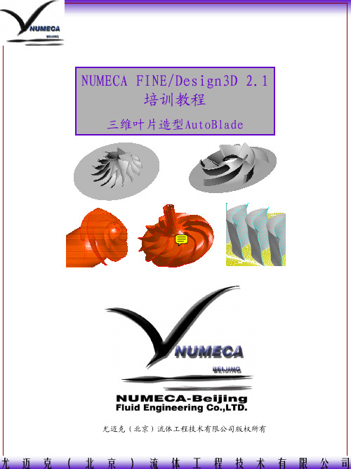
3. Cubic-B Spline(n control points):三次B 样条曲线,由n×2个参数来控制,控制点分别为 各个点的Z、R坐标,用户可定制控制点数目(界 面中“Number of control points”),曲线三阶 光顺。 *曲线通过控制点
这五种模板几乎可以囊括所有的旋转机械类型,例如离心泵/向心透平/混 流式结构/回转弯道等都可以采用Centrifugal Compressor 或者Centrifugal Compressor With Splitter的模板来进行生成
Page 7
尤迈克(北京)流体工程技术有限公司
Step 3. 端壁定义
用户可以通过导入数据文件来定义端壁形状
数据文件格式:
n (离散点个数)
5
Z1 R1
0.0
0.15
Z2 R2
0.05
0.15
Z3 R3
0.1
0.14
……….
…………..
Zn Rn
0.2
0.13
*注:在导入数据选项中,用户可以选择控制点的连接类型
interpolation type: polyline or cubic spline,分别对应折线
3.1 3.3
3.2
Page 6
尤迈克(北京)流体工程技术有限公司
Step 2. 项目管理
*1. 新建工程项目或者打开已经存在的工程文件(.par)
NUMECA帮助文档

第十二章跨叶片截面模块12.1绪言本章针对透平机械讲述快速三维跨叶片截面模块的分析过程。
这个模块是全自动完成的并且利用一些NUMECA工具。
此外,附加模块FINE™/Design2D这些工具联系起来,可以进行叶片重新设计,改善叶片表面压力分布,关于这些详见第13章。
这个模块假设流动是轴对称的,并且流面形状和厚度也由用户提供或由参数自动生成(利用根部和顶部边界)。
几何输入数据必须由用户提供:1、流面及叶片这个流面上的截面或2、完整的叶片轮廓及端壁本模块由网格自动生成及NS湍流方程组成。
在下一节讲述这个跨叶片截面模块的界面及对用户的建议。
12-4节讲述自动生成网格的理论和求解方程。
12-5节讲述几何数据和输出结果。
12-6讲述实例。
12-2跨叶片截面模块的界面在FINE™/Design2D界面之下运行跨叶片截面模块,这些可以高速,简单,交互式求解。
所有参数可以在用户界面中选取,并自动创建输入文件及求解。
监视工具,MonitorTurbo,可以在计算中和计算后检查收敛情况及结果。
它可以实时查看叶片表面压力分布的收敛过程及叶片几何形状。
结果分析利用 NUMECA CFViwe™后处理工具进行,自动进入跨叶片截面模式。
几何数据以ASCII输入文件列出,但是求解参数定义及边界条件在这个界面中列出。
这个截面的描述由FINE™/Design2D界面中的菜单创建。
更详细的说明见12-5.12.2.1开始新的或打开现存S1面计算在开始界面下,Project Selection窗口允许创建新工程或打开现存工程。
对于创建新的跨叶片截面工程,按如下操作:1、单击按扭Create a New Project2、选取工程保存路径及输入文件名3、关闭Grid File Selection窗口,Design 2D不需要输入网格文件4、进入S1流面模块,菜单Modules/Design 2D如果要打开现存工程,在Project Selection窗口中单击Open an Existing Project 按扭,并在File chooser窗口中选取一个文件。
NUMECA使用手记
NUMECA 使用手记1.右手坐标系和右手系1 右手坐标系:X轴向右,Y轴向上,Z轴向自己。
2 右手系:一个空间直角坐标系,如果当右手(左手)的大拇指指向第一个坐标轴(x轴)的正向,而其余手指以第二个轴(y轴)绕第一轴转动的方向握紧,就与第三个轴(z轴)重合,就称此坐标系为右手(左手)坐标系。
2.2009.1.21建立叶轮模型所遇到的问题1 流道的方向定义为沿z轴的正向。
2 采用线来生成叶片时,lofted的方向为从盘侧指向盖侧,而不能相反。
3.使用Fine_turbo进行计算时所考虑的问题1 采用拟可压模型时各个参数的含义,例如β。
2 压比的含义如何处理。
4.使用问题1.单流道模拟时,输入的流量是整机的流量还是单一流道的流量。
2.在IGG 中,insert vertex和insert fixed point 有什么区别和联系。
Vertex 不会分割网格的边,而fixed point 则会分割网格的边为“two segment”。
3.在制作网格,给网格分区时,应采用insert fixed point。
4.在疏网格上的计算会不会出现效率超过“1”的可能。
5.Y+的含义是什么,如何确定。
5.流体中文网论坛的帖子关于低速流动和不可压流动对于低速流动(Ma<0.3),尤其对于马赫数小于0.1的流动,工质的可压缩性非常弱,此时,应当启用PRECONDITIONING选项,进行预处理。
此时,请注意参考速度的选取方式,应当为进口或者出口的绝速度值,而不应当随意给。
这对于计算的收敛性很有影响。
对于不可压缩流动(例如液体),则也应当采用PRECONDITIONING方法。
6.分割面1. 先插入内部分割线“insert internal grid line”.2. 利用“boundary conditions”下的“edit patch”来分割patch,获得新的面。
7.复制网格在建立整个叶轮的网格时,要复制单一流道的网格,例如整个叶轮的流道数目为12,则在输入复制数目时应为11,但是在输入角度时,仍需要输入N=12.8.进口流量的设定单通道时也是设定整机的流量。
Numeca使用-Fine

计算参数设定
主要步骤
• 导入网格 • 几何参数设定 • 边界条件设定 • 数值计算参数设定 • 初场条件设定 • 输出参数设定 • 计算控制参数设定
导入网格
• 注意事项 • 单位
几何参数设定
• 工质设定
几何参数设定
• 流动参数设定
➢ 定常、非定常选择 ➢ 湍流模型选择
几何参数设定
• 轮毂、叶片
• 转动方向
数值计算参数设定
• CFL数设定 • 计算网格层数 • 非定常双时间步长设定
初场条件设定
• 均匀场 • 已有收敛解 • 交界面静压
初场条件设定
• 均匀场
• 对某些特殊情况可以采用将网格重新组合并分别 给定初场的方式,如:多极情况下机匣处理,吸 附开槽等
初场条件设定
• From file
边界条件设定
• 进口边条
• 总温、总压 • 来流方向
边界条件设定
边界条件设定
• 出口边界条件 • 平均静压 • 某半径静压 注意
平均静压收敛性较好,但在出口压力场分布极不均 匀且得不到有效掺混时不宜采用这种给法。 应采用给定某半径处静压、壁面静压或已知压力分 布
边界条件设定
• 固壁边界条件 • 转动部件选取
• 流动参数设定
➢ 雷诺数计算相关参数 ➢ 特征长度:等效流通直径 ➢ 特征速度:进口速度 ➢ 参考温度、参考压力
几何参数设定
• 流动参数设定
➢ 转动块定义 ➢ 所有与转动相关的BLOCK都必须转动 ➢ 转、静子交界面设定 ➢ 掺混面模型
• 转静子交界面参数传递
非定常几何参数设定
• Domain scaling
• 物理时间步长设定 • 2D: 弦长/(速度*20~30) • 3D: 60/(n1*n2*n3) n1:转速(nps);n2:叶片数;n3:相位于近似几何结构但不同网格可以采用修改已有 收敛解的*.RUN文件,来做初场
numeca教学
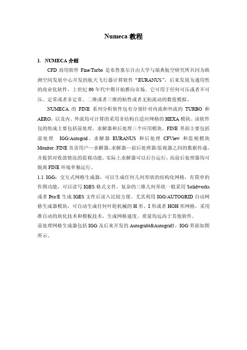
一般不用将叶轮所有叶片和轮盖造型出来, 只需一个叶片即可, 如下图所示。
生成实体后,保存为 iges 格式文件,然后在 IGG 中打开。 2.2 处理几何数据
2.2.1 如上图所示,在 IGG 中打开 2.1 中得到的 iges 格式文件,然后取出 ps1, ps2,ss1,ss2 线。这里 ps 指的是 pressure surface,即压力面,ss 指的是 sucktion suface,即吸力面,1 指的是叶根,即叶片压力面或者吸力面与轮 盘交接的一端,2 指的是叶顶,即叶片压力面或者吸力面与轮盖交接的一 端。 2.2.2 对于二元叶片,不需要通过造型——取线的方式得到 ps1,ps2,ss1,ss2 线,只需要对叶片型线的坐标数据进行处理,制作出.dat 数据文件。 在一个.txt 文本文件中,前三行分别输入: #文件名(ps1 或 ps2 或 ss1 或 ss2) 坐标系(zr 或 xyz,这里是对叶片型线处理,所以用 xyz 坐标系) 坐标点数 从第四行开始输入坐标点。 数据输入完成后,将.txt 文件名后缀改为.dat。 2.2.3 将文件名分别为 ps1,ps2,ss1,ss2 的文件制作完成后,再重新导入 IGG, 利用放样(loft)功能,将 ps1,ps2 线生成 ps 面,ss1,ss2 线生成 ss 面。 2.2.4 制作轮盘,轮盖的几何数据文件。 同 2.2.2 中相同,由轮盘(hub) ,轮盖(shroud)的坐标得到相应的.dat 文
2
n
1
(n >2)
多重网格的层数为:min(n)+1 如:17=24+1,min(n)=4,即满足 5 重多重网格。 61=25+24+23+22+1,min(n)=2,即满足 3 重多重网格。 对于网格质量报表, 这里一般只关心 negtive cells (负网格) , min skewness (最小正交度),max asp ratio(最大长宽比) ,max exp ratio(最大延展比)四 项指标。 正交性(Orthogonality) :网格相邻两条边之间相互垂直的程度。二 维标准,范围 0-90°。正交性表征网格面两条边之间的最小角度。如果两条 边的夹角大于 90°,则正交性按(180-实际角度)确定。 长宽比(Aspect Ratio):如图示。二维标准,范围 1-10000。如果实 际值超出这个范围,重置为 10000。
numeca经验浅谈
numeca经验浅谈NUMECA使用技巧:A、网格生成1、首先想办法将叶轮等的Hub、Shroud曲线取出,最好存成.dat文件。
由于Hub、Shroud曲线都是二维的,大多是RZ坐标,所以可以自己编程、或者使用电子图板等软件实现。
本人一般都是用电子图板软件将叶轮子午面做出,然后使用其取点坐标功能将需要曲线的数据点取出。
该软件可以控制Hub、Shroud曲线数据点的稀疏。
2、叶片压力面、吸力面的数据对于由直线元组成的叶片或者二元叶片来讲,只要定了压力面、吸力面侧Hub、Shroud 曲线,两个曲面即可确定。
如果是三元叶片,则需要多条曲线才可确定。
对于前者,我们可以使用1的方法将所需曲线取出;对于后者,可以使用SolidWorks、Pro/E等软件将叶轮三维图做出,存为.iges文件,然后导入到numeca中。
3、叶轮模型的完成有了1、2步骤的准备,可以按照NUMECA MANUAL中所说的将hub、shroud文件导入,再将PS、SS面确定。
也可以直接根据相应的格式写出.geomTurbo文件,然后在Autogrid中直接调入.geomTurbo文件。
4、1~3就完成了叶轮模型的建立,下一步就是具体划分网格了。
比如流向、叶高方向、跨叶片方向分别取多少网格节点,cell width取多少等等。
其中cell width参数是一个比较重要的参数,可能会影响你的流场计算。
大家可以根据NUMECA MANUAL中的那个y+公司来决定。
对于特定的模型,y+都有一个大致范围,y+定了,cell width根据上述公司即可计算出。
5、调试网格质量,先保证无负网格,然后调试至合理的网格正交性、长宽比等参数。
B、流场计算,Fine参数设置1、根据算例的具体情况,仔细设置本算例进口、出口条件。
这点十分重要,因为算例正确与否,主要依据你的进出口条件正确与否。
我在计算时,一般是给定进口的总压、总温进口气流方向。
出口是给定质量流量。
Numeca 画网格快速入门教程
Numeca 画网格快速入门教程本教材以一个典型的带分流叶片的离心叶轮为案例,采用铺网格面的方式重构几何,最后在AG5里画网格的一个标准流程。
可以快速入门,并且能得到质量很好的网格。
Step 1:打开IGG, 从菜单 File,Import,IGES导入原始几何文件,这里也可以导入其它格式的几何文件。
Step 2:在IGG的操作区域内单击右键,在弹出菜单中选择SelectSurfaces(也可以用快捷键Strl+s),选择所有的面(快捷键a),然后再单击右键,选择hide select surfaces。
如果单击右键弹不出右键菜单,那说明你目前在命令操作中,再按右键就可以退出。
一般在命令操作中时,操作区域的最下方会有一些提示。
图下方的一行黄色的字就三操作提示,同时也表示目前处于命令操作中,再按右键,这一行字就会消失。
Step 3:选择左侧的Geometry,curve,CSpline命令,从hub线的入口端开始,隔一定长度点击一次,一直到出口端点,在原来的几何线上转换一条新的CSpline 线,操作完毕后,该线处于选中状态(黄色),此时可以直接File,Export,Geometry Selection…输出为hub.dat。
然后单击右键弹出右键菜单,选择select curve,按下a,即取消所有线条的选中状态。
再重复上述操作,完成shroud线的制作和输出。
Step 4 :操作完成后,单击右键,选择hide all Geometry,隐藏所有几何文件,也可以选择所有线条隐藏。
然后再菜单Geometry,view ,surfaces, 在弹出对话框中选择所有的面,apply之后,我们之前隐藏那些面又出现了。
这里当然也可以用工具栏的view下的geomtry,geomtry groups来分组几何,这个功能在面对几何比较多的时候很有用,可以快速实现几何的隐藏和显示。
step 5:选择工具栏Grid,create,Insert new face 就是第三个,将face grid 的四个顶点分别附着在叶片面的四个顶点上。
NUMECA使用准则V1[1].0
![NUMECA使用准则V1[1].0](https://img.taocdn.com/s3/m/c86416114431b90d6c85c77a.png)
NUMECA使用准则V1.0尤迈克(北京)流体工程技术有限公司编写2008年3月目 录一. 计算域的设定及几何一致性 (3)二. 网格质量相关性 (4)三. 边界条件设置 (5)四. 收敛判别标准 (5)五. 流场特征分析基础 (6)六. 文件夹管理标准化 (8)附:4个标准化计算和检查文件 (8)附录1:文件管理布局 (9)附录2:叶片网格生成流程图 (10)附录3:计算设置检查流程图 (11)一. 计算域的设定及几何一致性为了保证数值计算结果的准确性与可信度,几何一致性就显得至关重要。
在准备几何数据,提取几何完成之后,在IGG中测量检查叶轮几何文件(*.geomturbo)和蜗壳几何文件(*.dat)尺寸与原始二维/三维CAD图纸相一致,下一步的网格划分就是对现有几何空间的离散化,以此来控制数值模拟误差的几何误差部分。
一般地,几何数据可通过三种途径获得: CAD文件、数据文件或加工图纸、。
如果是CAD文件,则要在CAD软件中仅选中与流动部分(如叶片,流道内侧的几何、蜗壳内侧的几何等)相关的几何线或面,输出为NUMECA软件可辩认的格式(如IGES、Parasolid、Catia等格式)。
当把这些文件输入到IGG或IGG/Autogrid 中时,首先要查对是否有线或面遗漏。
在确认都正确的前提下,再开始制做网格。
如果是加工图纸或数据文件,就要通过IGG(如果几何比较简单)或任意CAD软件把加工图纸转换成CAD文件,再重复上面的工作。
如果只做叶片流道部分的数值模拟,那么加工图纸或数据文件给出的只是叶型和子午流道的几何,这样就可把加工图纸转换成数据文件,并写成IGG可辩认的格式,直接读入到IGG/Autogrid中。
读入以后,也要先认真检查叶片和流道的几何是否正确,特别是叶片的安装角是否正确,叶轮转向是否正确,叶轮进口为Z轴正方向等。
还要注意叶片在轴向的安装位置是否正确。
叶片排之间的周向位置尽量重合,对计算结果没有任何影响,但方便在后处理中对流场结果进行对比分析。
- 1、下载文档前请自行甄别文档内容的完整性,平台不提供额外的编辑、内容补充、找答案等附加服务。
- 2、"仅部分预览"的文档,不可在线预览部分如存在完整性等问题,可反馈申请退款(可完整预览的文档不适用该条件!)。
- 3、如文档侵犯您的权益,请联系客服反馈,我们会尽快为您处理(人工客服工作时间:9:00-18:30)。
45. 关闭这个[M-theta grid Control] 对话框。 46. After selecting the view, move the mouse near the leading edge control point and until it is highlighted
as shown in the below figure.
2-4.2 第二步: 调整子午面
帮助文件说这个对话框是自动弹出的,我没有看到它的配合!点击
这
个按扭,不过出来的是[ Streamlines Control]
22. 在[Number Of Points to define Flow Paths ] 框中输入 150
23. 单击这个对话框右下角的[Apply] 按扭 24. 选择[Expert],mode(3), 图 2.4.2-1 (4)
25. 单击这个对话框右下角的[Apply] 按扭 26. 关闭这个[Expert] ,mode(3), 27. 激活[Tip clearamce],并单击框[Tip clearance Parameter]的[On]
如图 2.4.2-2 中 (1) (2)
28. 在[Tip ClearanceWidth at Leading Edge]和[Tip ClearanceWidth at Trailing Edge]两框中输入 0.000356m.并确定。如图2.4.2-2中 (3) 29. 在[Number of points at Spanwise Direction]和[Number of points at Azimuthal Direction]框中分 别输入13 , 17 . 如图2.4.2-2中 (4) 30. 单击[Apply] , 如图2.4.2-2中 (5)
73. 单击
这个图标,查看生成的网格。
74. 单击
这个图标,四个视图逐一显示。
2-4.6 第六步:保存这个网格和网格参数
75. 在主菜单File中选择 76. 在主菜单File中选择
,保存网格文件,(*.igg 格式) ,保存网格设置文件,(*.trb 格式)
77. 在主菜单modules中选择Fine Turbo. 退出IGG/AutoGrid并启动求解器! 2-5 FINE求解 2-5.1 工程控制台 Project Management 78. In the FINEinterface project parameters, select the item Project Management/Project Settings (default). 在Import a grid file 中输入刚刚保存过的*.igg格式的文件。
18.修改网格参数,此时面板上默认的数既为要输入的数字。 19. 修改第一个单元的网格宽度。(Calculate the value of the first cell width.) 20. 修改 Hub & Shroud and Blade 上的网格参数,使网格宽度小于 3e-6 m. 2-4.1.3 Bulb,Seal Leakage & Propeller 21. 单击对话框上的[Check & Accept] 按扭。 (偶没有找到这个按扭,悲) ( 在 下 图 中 , 下 侧 的 三 个 按 扭 [Apply], [Accept][Generate 3D], 这 只 是 NUMECA6.0 之前的哪个版本才是这样,我用的是 6.1 版本,只有两个按扭, 分别是[Close] [next],没有错误了就按[Next] ) 天不遂人愿,我用的软件和帮助不是一个版本,举凡皆是,痛!
11.单击
,放大 HUB 窗口至如图 2.4.1-4 形式。
12.使[Leading Edge at M Minimum]这个按扭无效。
13. 使 [Geometry Definition]和[Surface Edition]这两个按扭无效。关闭这面板 上的这片区域。 14. 激活[Geometry]标签下的[Geometry Characteristics]按扭。扩展面板并在这 里输入新的参数。
2-1.2 理论 这是一个典型的例子
2-2 例题描述 (case description) *亚音速,可压缩,轴向流动 *流体:空气 *工作转速:17188rpm
2-3 FINE 求解方案 1. 运行 FINE,必须有下列条件;在 Unix 系统下 type fine(FINE 类型?) 单击(Return),在 PC/NT 双击 FINE 图标 2. 在 FINE 菜单中新建一个(project), [Project/New] 3. 输入新项目的名字(rotor37.iec) 此时 FINE 会自动在当前目录下创建一个 文件夹,文件夹名为刚输入的名字(rotor37) 4. 单击创建网格,程序自动转到 IGG,在 IGG 中,[选择 Modules/AutoGrid] 2-4 IGG/Autogrid 几何结构和网格创建 2-4.1 第一步:几何和网格创建
创建2D网格的五种方法。本文略! 到这里的每一步与6.1版本中的方法大不相同,在6.1版本中执行操作后按 [Next]即可接着进行下一步操作。我的感觉是现在的版本是按流程进行操作, 只是多了流程控制。 2-4.5 第五步:创建3D网格
71. 单击Байду номын сангаас
这个图标,创建3D网格
72. 单击 OK (两次) 6.1中没有这一步!
2-4.4.3 Blade to Blade mesh. 网格质量控制
39. 单击这个
Mesh Boundaries Control图标
40. 单击[Show Edges] 按扭在这个[M-theta Control]对话框。图2.4.4-3
设定进出口边界
- Inlet 1 is the periodic extension, upstream of Leading Edge 1 - Inlet 2 is the periodic extension, upstream of Leading Edge 2 - Outlet 1 is the periodic extension, downstream of Trailing Edge 1
2-4.3 第三步:进出口延伸面控制 35. 没有实际上的操作,关闭这个对话框 2-4.4 第四步:生成网格 2-4.4.1 边界网格点
36. 单击这个
网格边界创建图标
37. 自动生成网格
2-4.4.2 hub(根部)和shroud(顶部)的表面网格
38. 单击这个
Blade to Blade Mesh图标
(lower left)= 29; Outlet 1 (upper right) = 33; Outlet 2 (lower right) = 61.
43. 单击[Apply] 如图2.4.4-6 (3)
44. 单击 这个 网格。
[Blade to Blade Mesh] 图标,创建Hub和Shroud的2D
此时应该能看如下图所示的内容:
四个窗口的内容不用我说了吧,很清楚。 8.选中如图 2.4.1-1 中的(1)[Geometry Definition]和(2)[Surface Edition],这时对 话框展开,如图 2.4.1-3 准备输入新参数
9.单击(3)[merge Blade],四个窗口的内容被拟合(=fit) 10.激活四个窗口中的 HUB 窗口,在左下图中单击,此时窗口多了一个红色 边框
- Outlet 2 is the periodic extension, downstream of Trailing Edge 2
41. 单击[Point Distribution]这个按扭,控制周期性边界上的点数。 42. 输入以下各项(and press <Return> each time): Inlet 1 (upper left) = 61; Inlet 2
79. 在主菜单Mesh中选择Properties.设定度量单位。 80. In the Project units section, choose meters as the rotor37.geomTurbo file contained the geometry
in meters (default)
15. 在[Number of blades]框中输入 36,单击[Define Corner]按扭。 16. 使[Geometry Characteristics] 按扭无效。缩小这个面板。 2-4.1.2 拓朴 17. 单击对话框中的[Topology]标签,显示拓朴这一页。
这时可以选择网格的形式 H&I 或 HOH。网格形式不同,输入参数也不同。
81. In the Computations area, rename "computation_1" in "coarse_choked" 2-5.2 步长和时间步设置 82. 步长和
1- Keep the c-spline type defined by default for the flow path curves. 2- Keep the orthogonality control of the meridional mesh: off. 3- Define the grid points distribution on the hub as Uniform (instead of Curvature). 4- Define the grid points distribution on the shroud, as: Same as the hub.
a) I- or H-type mesh b) Control of the grid points distribution at the leading and trailing edge. c) Control of the streamwise clustering by using the projected control points d) Control of the matching points near leading and trailing edges e) Advanced treatment: local smoothing
