ADV8005:视频信号处理器
通信基站远程视频方案
通信基站远程视频解决方案成都华迈通信技术有限公司2014-5方案特点一、安装及布点速度快,工程建设周期短二、全新平台化管理,系统稳定、功能完善三、全实时视频监控,监控效果更胜一筹四、本地PC存储、SD卡录像与远程服务器集中录像相结合,数据三倍安全五、优化的H.264压缩格式,创造最低码流,适应所有网络带宽六、强大的设备功能,完全满足用户的看、听、说、防、控七、系统灵活,扩容性强目录第一章、概述 (5)1. 项目背景 (5)2. 建设目标 (5)3. 建设原则 (6)第二章、方案介绍 (7)1. 系统优势 (7)2. 系统功能 (8)第三章、系统设计 (9)1. 系统结构图: (9)2. 采集终端介绍 (9)3. 中心处理端介绍 (11)4.应用终端介绍 (13)第四章、系统部署 (16)1. 系统组网拓扑图: (16)2. 前端监控点 (16)3. 防雷设计 (17)4. 中心管理平台 (17)5. 监控中心 (18)6. 系统管理 (18)7. 网络要求 (18)第五章、方案优势 (19)1. 监管终端接入极其便利 (19)2. 无需新建专业视频服务器 (19)3. 分级分区域管理 (20)4. 全系产品支持手机视频监管 (20)5. 经济便利组网 (20)6. 完善的平台搭建方案 (20)第六章、设备选型 (21)1. 高清720P红外有线网络卡片机 (21)2. 室外增强型红外防水枪形机 (24)3. 高清720P国产红外网络高速球 (27)第七章配置清单 (30)第八章售后服务 (30)第一章、概述1.项目背景通信业务与人民的生活已息息相关,为用户提供优质、满意的服务已成为通信行业的重要任务。
所以基站的全面建设是非常重要的,目前通信基站覆盖范围已经非常广,涉及高山和偏远的乡村都已经有移动基站的建设。
这为移动通讯的信号覆盖做了很大的努力。
但是基站的监控也成了非常大的难题。
随着移动网络的全面改造,为了提高工作效益,各移动基站均要实现无人值守。
大视电子 MM5000 飓风系列 超高清拼接处理系统 说明书

MM5000飓风(Tornado)系列超高清拼接处理系统说明书Multiple views, multiple lives上海大视电子科技有限公司兼容灵活MM5000飓风(Tornado)系列超高清拼接处理器面板图(1.5U,2U,3U,8U,12U,18U,26U)MM5000飓风(Tornado)系列超高清多屏拼接处理器是采用纯硬件线速处理架构的高性能视频图像处理系统,适用于教育科研、政府公告、信息出版、行政管理、军事指挥、展览展示、安防监控、商业销售等行业。
它集多路高清、超高清视频信号采集、实时高分辨率数字图像处理、复杂图像变换处理等高端图像处理功能于一身,具有强大的信号处理能力。
运行流畅无损画面l架构设计l➢纯硬件FPGA架构无内嵌操作系统,内部自建高性能处理算法,图像处理性能优异。
全新的大视电子第四代硬件处理架构,Flexview M8核心处理算法,具备图像信号全硬件点对点能力,4K/8K多路超高分信号处理支持,实时无损处理,独有全帧保持技术保证无丢帧现象,超并行处理机制和全同步处理架构,保证所有输出严格全同步,所有画面无撕裂。
l 输入卡l➢任意组合多种输入卡DVI-M、HDMI、Displayport、VGA、DVI、DualLink DVI、SDI、CVBS、HDBaseT、YPbPr/YCbCr、IP、光纤等。
➢超高清输入卡支持最高8Kx4K超高分辨率输入,支持多接口分辨率组合➢输入卡任意混插机制实现输入扩展的极大灵活性l 输出卡l➢支持800x600-2048x1200@60Hz分辨率,同时支持主动立体输出 1024x768-1280x800@120Hz➢超高分输出卡支持1920x1080@120Hz 及4K@60Hz,4K@30Hz分辨率➢输出支持冗余备份输出,防止意外静电损坏。
➢输入输出支持自定义任意拼接,可选任意角度旋转和任意间距创意拼接,支持0-360度旋转,1度为单位(该功能为选配)l 系统连接及控制l➢支持网络和RS232串口调试,支持系统定时,同时提供额外RS232串口,可以控制矩阵/投影机等。
五通道切换台 HDS7105P VER 1.0 使用手册说明书

使用手册五通道切换台HDS7105PVER 1.02HDS7105P安全须知如果忽视这些注意事项,可能导致人员伤害或伤亡,可能导致设备损坏、数据丢失、设备性能降低或不可预知的结果。
电器安全特性● 为避免可能的电击造成严重损害,在搬动产品之前,请先将电源线暂时从产品电源接口处移除。
● 当您需要加入新的硬件到产品中或移除产品中现有硬件时,请务必先关闭产品电源。
条件允许的情况下,建议将电源线暂时从产品接口处移除。
● 使用前应确认产品是否已接地,电源电压是否已调整到产品适用的范围内。
否则将可能导致产品以外损坏、性能降低或不可预知的结果。
● 请勿使用松动或损坏的电源插座或在手潮湿的时候接触电源插座,否则将有触电和起火的危险。
● 若听到电源线和电源接口处有噪音,请立即拔下电源线,并向您的销售代表寻求帮助,否则将有起火或触电的危险。
● 若如有异物或液体进入产品或需要清洁产品时,请从产品上移开电源线以及其他的任何电缆线,否则将有触电、起火和损坏产品的危险。
● 若电源已损坏,请不要尝试自行修复。
请联系专业技术服务人员或经销商来处理。
3目录1.概述………………………………………………………………………………………...04 1.1 产品介绍………………………………………………………………......042.功能特性…………………………………………………………………………….…. .052.1 设备尺寸...............................................................................06 3.接口规格说明......................................................................................07 3.1 接口介绍...............................................................................07 3.2 TALLY 接口............................................................................08 3.3 接口参数...............................................................................09 4.控制面板及接口..................................................................................10 4.1 控制面板.. (10)4.1.1 分区说明........................................................................10 4.1.2 按键说明 (11)4.1.2.1功能区.................................................................11 4.1.2.2 音频控制区.. (11)4.1.2.3 转场特效控制区................................................14 4.1.2.4 综合控制区........................................................15 4.1.2.5 PGM 与PVW 的选择. (17)5.系统菜单设置.......................................................................................20 B 接口对接OBS 软件说明.............................................................21 7.切换台软件控制...................................................................................25 8. 同步地区时间和升级固件操作说明.............................................. 29 9.故障及维修............................................................................................34 10.更多切换台选择. (35)4中帝威(DeviceWell)高清视频切换台HDS7105P ,采用便携式一体化设计,金属外壳,体积小重量轻,标准尺寸:280mm*110mm*47mm ,可适用于小型外出场景的视频特效切换需求。
ADI推出NatureVue超高清视频信号处理器
ADI 推出NatureVue 超高清视频信号处理器
中国,北京Analog Devices,Inc.(NASDAQ:ADI)最近推出一款
超高清(UHD)视频信号处理器,这款处理器可以在SD (480i)、ED (480p)、HD(720p、1080i 和1080p)以及UHD (2160p)等视频格式之间进行上下转换。
UHD NatureVue™ ADV8005 视频信号处理器可为两个同步视频流提供多种屏幕分辨率,适用范围十分广泛,从A/V 接收器和
HDMI 分频器到商业视频分发系统和数字标牌。
这款新型处理器可以在内部
产生高质量的位图式屏幕显示(OSD),允许设计师轻松集成滚动文本和动画
等功能,色深最高可达24 位真彩色。
同时还可接受来自外部源(如图形处理
装置)的OSD 信息。
- 下载数据手册,观看视频,订购样片和评估板:analog/zh/pr0108/adv8005
- 通过在线技术支持社区EngineerZone™联系工程师和ADI 产品专家:ezchina.analog/community/video
- 更多有关产品信息,请致电亚洲技术支持中心:400 6100 006,或发送邮件至china.support@analog ,也可点击ADI 官方微博weibo/analogdevices ,或通过手机登录m. analog 或analog 了解最新产品等。
Michi P5 立体声前置放大器 使用说明书

P5Stereo Control Amplifier立体声前置放大器Owner’s Manual使用说明书注意后板上的RS232接口仅由授权人士操作。
警告:机内无客户可以维修的部件,请合格的维修人员维修。
警告:为减少火灾或触电的危险,不要将本产品置于潮湿环境中或水中。
不要将本产品置于滴水或溅水环境中。
不要将含有液体的物件(例如花瓶)放在本产品上。
不要让异物进入本产品外壳内。
如果本产品进入潮湿环境中,或异物进入本产品内,立即从墙上拔掉电源线。
将本产品送交合资格维修人员检查或进行必要的维修。
请仔细阅读所有说明。
请保留所有说明手册。
请留意这些说明和装置上的所有警告。
请遵从操作说明。
不要在接近水的地方使用本产品。
只能用干布清洁。
不要堵塞本装置任何通风口。
请依照制造商的指导进行安装。
请勿将本装置安置于靠近辐射、热源、火炉或其它发热器具(包括放大器)的地方。
请注意两极插头或接地插头的安全作用。
两极插头有两个插刀,其中一个插刀比另一个宽。
接地插头有两个插刀和第三个接地插刀。
这些都是为了您的安全。
如果随本产品提供的插头与您的插座不匹配,请咨询电工更换陈旧的插座。
易插座以及从本装置拔插的部分。
只能使用制造商指定的附件或配件。
只能使用制造商指定或随本装置一同出售的机架、立架、支架或桌子。
在支架或机架上移动本装置时,请小心避免因机器或机架翻倒导致受伤。
雷暴天气中或本装置长时间不使用时,应将电源插头从插座中拔出。
若本装置有任何损坏,如电源线或插头损坏,异物或液体进入装置中,本装置遭受雨淋或受潮,本装置显示不正确操作的迹象或本装置跌落时,立即停止使用,并请合格维修机构检测和维修。
本产品应在非热带气候条件下安全使用。
请勿用报纸、桌布、窗帘等物品遮盖通风口,以免阻碍通风散热。
请勿将本装置安置于有明火源的地方,如点燃的蜡烛。
触摸未绝缘的端口或电线可能引起您的不适。
Michi产品符合电气和电子设备限制有害物质(RoHS )以及处理废旧电气和电子设备(WEEE )的国际指令。
ADV7842_cn(HDMI接口芯片)
特性
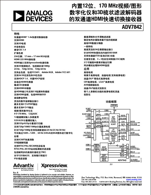
双通道HDMI® 1.4a快速切换接收器 支持HDMI 支持3D电视 内容类型位 兼容CEC 1.4 扩展色度 256引脚、17 mm × 17 mm BGA封装 HDMI 225 MHz接收器 HDMI端口支持Xpressview快速切换 支持3D视频格式,包括帧封装1080p 24 Hz、720p 50 Hz、720p 60 Hz 支持全色度,包括YCC601、Adobe RGB、Adobe YCC 601 支持36/30位深色和24位色彩 支持HDCP 1.4、内置HDCP密钥 自适应HDMI均衡器 集成CEC控制器 支持HDMI中继器 各HDMI端口均支持5 V检测和热插拔 支持HDMI音频,包括HBR和DSD 高级静音特性 灵活的数字音频输出接口 最多支持5个S/PDIF输出 最多支持4个I2S输出 视频/图形数字化仪 4个170 MHz、12位ADC 12通道模拟输入多路复用 525i/625i分量模拟输入 支持525p/625p分量逐行扫描 支持720p/1080i/1080p分量高清电视 针对720p/1080p支持低刷新速率(24 Hz/25 Hz/30 Hz) 可对高达1600 × 1200 、60 Hz (UXGA)的RGB图形进行数字化 处理 支持SCART快速消隐 3D视频解码器 支持NTSC/PAL/SECAM色彩标准 NTSC/PAL 2D/3D运动检测梳状滤波器 包括帧同步的高级时基校正(TBC) 对于525i和625i,支持隔行转逐行 IF补偿滤波器 垂直调峰和水平调峰滤波器 稳定地同步提取质量不佳的视频源 高级VBI数据分隔器 一般特性 高度灵活的36位像素输出接口 针对HDMI和图形的内部EDID RAM 支持双通道STDI(标准识别)功能 任意至任意、3 × 3色彩空间转换(CSC)矩阵 2个可编程中断请求输出引脚 同步模拟处理和HDMI监控
全彩LED视频处理器

XP520-全彩LED视频处理器产品说明书北京拓北技术有限公司先进的十位处理能力、隔行运动图像自适应处理技术,消除视频图像运动拖尾和锯齿现象,输出图像更加清晰细腻,输出的图像细节丰富,色彩饱满可自定义输出分辨率,最大输出分辨率可达2560*1440或3840*960高清字幕,LOGO叠加冻结画面功能及数字键精确输入功能输入信号间无缝切换、淡入淡出切换、融合切换可按计划循环播放,自动热备份功能保障显示更稳定可靠精确的双画面输入图像截取功能,轻松实现点对点显示以及素材融合2路音频输入,兼容不同发送卡,双DVI输出、可内置2张发送卡安全注意事项1、禁止靠近火源或高温环境,并做好防水处理;2、本设备如发生异常现象,应立即关闭电源与售后联系;3、VGA、DVI、HDMI信号不要热插拔,请关闭电源后再连线;4、在有雷电或长期不用时请关闭电源。
质量保证承诺:1、拓北公司所有的产品承诺7天包退,从用户收到货物开始计算;2、拓北公司所有的产品承诺一个月包换,从用户收到货物开始计算;3、拓北公司所有的产品承诺五年保修服务,除用户人为损坏外一律免费维修。
技术支持承诺:北京拓北公司的视频处理器具有竞争对手产品无可比拟的智能化配置向导,用户在10秒内即可完成配置,而且无需对最终用户培训。
1、登陆公司网站,下载更加详细的产品说明书;2、登陆公司网站,下载上位机软件,通过R232串口连接和控制处理器;3、拨打技术支持电话:400-096-5768。
投诉与建议:希望通过我们的耐心服务,让您感受到拓北公司专业的技术支持。
拓北公司不仅仅是提供设备,同时,我们也免费提供优质服务。
如果您对我们的产品或服务有任何不满或建议,欢迎发送投诉邮件至,您的建议和投诉,是我们做得更好的动力;因此,您也可以在下次购买我们的产品时享受更多的优惠。
基于S7-1500PLC的运料小车自动化控制

基于S7-1500PLC的运料小车自动化控制摘要运料小车在现代化生产线上的应用非常广泛,负责原料的接收和输送。
对于运料小车的走行普遍采用PLC自动化控制,是工业自动化的一个典型应用,从而在工业生产过程中提高劳动生产效率,降低生产成本。
我们这个项目就是设计、开发一套完整的运料小车控制系统,模拟运料现车在实际工业生产中的运行,完成对运料小车的自动化控制。
关键词:PLC,运料小车,自动化研究背景随着科学技术的发展,社会对生产自动化的要求越来越高,原有的生产设备已经不能满足自动化生产的需求,,在自动化生产过程中,运料是一个十分重要的过程。
为了节省人力资源,经济资源。
基于PLC运料小车控制系统能够解决这个问题,因此项目设计具有了现实可实现性。
设计条件:运用S7-1500PLC设计运料小车控制系统,拟定以此作为核心完成对运料小车的走行,进行自动化控制。
包括工位检测、工位指示、运料小车的启停、电机的正、反转控制、定时接料、走行周期的计数等。
设计要求:1. 按下“启动”按钮,运料小车复位:即无论运料小车在任何位置,都将运行至原位位置(正转);2. 运料小车在原位位置SQ1,延时5秒后,运行至卸料位置SQ2(反转)停止;延时5秒后,运行至料斗位置SQ3(反转)停止;延时5秒后,运行至清洗位置SQ4(反转)停止;延时5秒后,返回至原位位置SQ1 (正转);3. 重复2,往复运行;4. 运料小车运行至SQ1-SQ4 4个位置时,相应位置的L1-L4指示灯以2HZ 频率闪烁;5. 计数:按下“启动”,计数清零;从SQ1-SQ4往复一次,计数加1;运料小车往复运行2次后,在SQ1位置自动停止。
6. 运行过程中按下“停止”按钮时,运料小车停止运行。
设备选型:根据设计要求,考虑到控制系统的先进性,PLC控制系统采用西门子的SIMATIC S7-1500控制器,这是西门子公司新一代的控制器,性能强大且高效,是西门子公司主推的未来主流产品。
视频输入信号说明书

- -
视频输入信号说明
本手册介绍的是该产品所支持的视频输入信号相关信息的变更。
《操作说明书》中相应的描述
3. 显示图像和写入信息 > 从计算机显示图像和写入信息 > 切换显示屏幕9. 附录 > 规格 > 外部接口
《操作说明书》的描述
视频输入信号必须满足以下条件:
信号必须遵从下列 VESA 标准之一:
计算机显示器计时 (DMT) 标准的行业标准和准则(第 版第 2 次修订)协同视频计时 (CVT) 标准( . 版)通用计时规则 (GTF)( . 版)信号必须满足以下信号条件:
变更的信息
视频输入信号必须满足以下条件:
信号必须遵从下列 VESA 标准之一:
计算机显示器计时 (DMT) 标准的行业标准和准则(第 版第 2 次修订)协同视频计时 (CVT) 标准( . 版)通用计时规则 (GTF)( . 版)
信号还必须是下表“VGA”列或“DisplayPort”列中用符号“”标识的其中一种信号:
• .2.3.•• .2.3.•交互式白板
- 2 -
VESA DMT:计算机显示器计时 (DMT) 标准的行业标准和准则(第 版第 2 次修订)VESA CVT:协同视频计时 (CVT) 标准( . 版)VESA GTF:通用计时规则 (GTF)( . 版)RB:降低清屏时间
如果输入的分辨率或信号频率与本产品不兼容,图像可能会闪烁、模糊或者在水平或垂直方向上较长。
更进一步就是图像可能无法显示。
本产品仅支持使用逐行扫描的设备。
••••••ZH CN
© 20 3 Ricoh Co., Ltd.
Y300-7580。
VGA视频和音频过Cat5 UTP扩展器 VGA视频和音频Cat5 UTP接收器 VGA视频和音频C

ST124UTPEA/ST128UTPEA STUTPEALR STUTPEA4XFCC Compliance StatementThis equipment has been tested and found to comply with the limits for a Class B digital device, pursuant to part 15 of the FCC Rules. These limits are designed to provide reasonable protection against harmful interference in a residential installation. This equipment generates, uses and can radiate radio frequency energy and, if not installed and used in accordance with the instructions, may cause harmful interference to radio communications. However, there is no guarantee that interference will not occur in a particular installation. If this equipment does cause harmful interference to radio or television reception, which can be determined by turn-ing the equipment off and on, the user is encouraged to try to correct the interference by one or more of the following measures:•Reorient or relocate the receiving antenna.•Increase the separation between the equipment and receiver.•Connect the equipment into an outlet on a circuit different from that to which the receiver is connected.•Consult the dealer or an experienced radio/TV technician for help.Use of Trademarks, Registered Trademarks, and other Protected Names and Symbols This manual may make reference to trademarks, registered trademarks, and other protected names and/or symbols of third-party companies not related in any way to StarT . Where they occur these references are for illustrative purposes only and do not represent an endorsement of a product or service by , or an endorsement of the product(s)to which this manual applies by the third-party company in question. Regardless of any direct acknowledgement elsewhere in the body of this document, StarT hereby acknowl-edges that all trademarks, registered trademarks, service marks, and other protected names and/or symbols contained in this manual and related documents are the property of their respective holders.Table of ContentsIntroduction (1)Features (1)Package Contents (1)ST124UTPEA/ST128UTPEA/STUTPEA4X (1)STUTPEALR (1)Hardware Guide (2)Local Unit - Front View (2)Local Unit - Rear View (2)Hardware Guide - Cont’d (3)Hardware Guide - Cont’d (4)Installation (5)Specifications (6)Specifications - Cont’d (7)Specifications - Cont’d (8)Distances/Resolutions (8)Wiring Information and Coding (8)Technical Support (9)Warranty Information (9)IntroductionThank you for purchasing a StarT video extension solution.ST124UTPEA/ST128UTPEA and STUTPEALR combine to create a cost effective method of providing high quality video (with audio) to remote locations over Cat5 UTP cabling.Features•Supports resolutions of up to1024x768 @ 60 Hz refresh rate at maximum extension distance; higher resolutions available with shorter cable runs•Delivers VGA video and audio to monitors located up to 300m / 950ft away•Can be used with a four port line splitterPackage ContentsST124UTPEA/ST128UTPEA/STUTPEA4X1 x Local VGA Video and Audio Extender••1 x Power Adapter•2 x Rack Rails1 x Screw kit for rack rails••1 x Instruction ManualSTUTPEALR•1 X Instruction Manual•1 X Long Range UTP Receiver•1 X Power Adapter - Class2 T ransformerHardware GuideLocal Unit - Front ViewLocal Unit - Rear ViewST124UTPEA ST128UTPEAST124UTPEA ST128UTPEAInput Power Jack1. VGA Output (HD-15 Female Connector)2. VGA Input (HD-15 Female Connector)3. AUDIO Input4. MIC Input5. MIC GAIN – adjust volume of microphone6. CAT5 OUT (RJ-45 Connectors): ST124UTPEA x47. ST128UTPEA x 8Remote Unit - Front ViewRemote Unit - Rear ViewSTUTPEALRVGA Output (HD-15 Female Connector)1. AUDIO Output2. EQ – Equalization length adjust (Adjust to sharpen images)3.GAIN – Adjust brightness4. Input Power Jack5. STUTPEALRLine Splitter - Rear ViewLine Splitter - Front View VGA Output (HD-15 Female Connector)1. CAT5 Input2. EQ – Equalization length adjust (Adjust to sharpen images)3. GAIN – Adjust brightness4. Power LED5. Input Power Jack6. CAT5 Output ports7.Installation1.T urn off the VGA signal source device (computer).2.Connect the local unit (ST124UTPEA/ST128UTPEA) HD-15 female INPUT connector to the signal source (computer) using an HD-15 male to male cable.3. AUDIO IN connector of the local unit (ST124UTPEA/ Connect theST128UTPEA) to the Audio Out port of the audio source (computer sound card), using a 3.5mm audio cable.4. Connect a compatible microphone cable to the MIC IN Optional:connector on the local unit (ST124UTPEA/ST128UTPEA).5.Connect a VGA monitor to the local unit (ST124UTPEA/ST128UTPEA) HD-15 female OUTPUT using an HD-15 male to male cable6. CAT5 OUT port Connect the Local Unit (ST124UTPEA/ST128UTPEA)to the Remote Unit (STUTPEALR) using CAT5 cable.Optional: If you will be using the STUTPEA4X Line Splitter, connect the Local Unit (ST124UTPEA/ST128UTPEA) CAT5 OUT port to the Line Splitter using CAT5 cable. Once the Line Splitter has been connected, you have the option of connecting to up to four remote units (STUTPEALR) using CAT5 cable.Once each of the Remote Units have been connected to either a Local 7.Unit (ST124UTPEA/ST128UTPEA) or Line Splitter (STUTPEA4X), connect a VGA monitor to the HD-15 OUTPUT connector provided by the remote units as necessary.Connect the Remote Unit8. AUDIO OUT port to the device you will be using to distribute audio (i.e. stereo receiver, amplifier etc.)9.Connect the power cord on all units (Local, Line Splitter, Remote). 10.T urn on the monitor and PC and audio amplifier.When situating the Local and Remote Units, please review themaximum distance capability offered by each component (foundin the Specifications sectionSpecifications Local UnitRemote UnitSpecifications - Cont’dLine Splitter Unit (STUTPEA4X)Specifications - Cont’dDistances/ResolutionsPlease note: It is recommended that CAT5 cable be used, as it offers superior performance to other standards. For example, CAT6:Wiring Information and CodingTechnical Support’s lifetime technical support is an integral part of our commit-ment to provide industry-leading solutions. If you ever need help with your product, visit /support and access our comprehensive selection of online tools, documentation, and downloads. Warranty InformationThis product is backed by a one-year warranty. In addition, StarTech.com warrants its products against defects in materials and workman-ship for the periods noted, following the initial date of purchase. During this period, the products may be returned for repair, or replacement with equivalent products at our discretion. The warranty covers parts and labor costs only. does not warrant its products from defects or damages arising from misuse, abuse, alteration, or normal wear and tear. Limitation of LiabilityIn no event shall the liability of Ltd. and USA LLP (or their officers, directors, employees or agents) for any damages (whether direct or indirect, special, punitive, incidental, consequential, or otherwise), loss of profits, loss of business, or any pecuniary loss, arising out of or related to the use of the product exceed the actual price paid for the product. Some states do not allow the exclusion or limitation of incidental or consequential damages. If such laws apply, the limitations or exclusions contained in this statement may not apply to you. has been making “hard-to-find easy” since 1985, providing high quality solutions to a diverse IT and A/V customer base that spans many channels, including government, education and industrial facilities to name just a few. We offer an unmatched selection of computer parts, cables, A/V products, KVM and Serv-er Management solutions, serving a worldwide market through our locations in the United States, Canada, the United Kingdom and T aiwan.Visit today for complete information about all our products and to access exclusive interactive tools such as the Cable Finder, Parts Finder and the KVM Reference Guide. makes it easy to complete almost any IT or A/V solution. Find out for yourself why our products lead the industry in perfor-mance, support, and value.。
Panther5-16 16通道五桥1080P数字视频录播器说明书
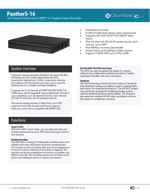
Panther5-1616 Channel Penta-brid 1080P 1U Digital Video Recorder●Embedded processor●H.264+/H.264 dual-stream video compression ●Supports HD AVS/ AHD/TVI/CVBS/IP video inputs●Max 24 channels (16+8) IP camera inputs, each channel up to 5MP●Max 96Mbps Incoming Bandwidth●Smart Search and Intelligent Video System ●Support 2 SATA HDD up to 8TB, 2USBSmart H.264+With the H.264+ Smart Codec, you can reduce bit rates and storage requirements by up to 70% without having to invest in new cameras.Flexible RecordingThe AVR offers a variety of configurable recording options and schedule that saves HDD space and active monitoring time. The recorder monitors incoming video and can be programmed to record if motion is detected or if an alarm is triggered. The recorder can also be programmed to record on a schedule or at different intervals. The recording options and schedules can be set for each individual camera or copied to all cameras..Clearview’s newest generation Panther5-16 adopts HD AVS technology, an over-coaxial-cable analog HD videotransmission standard and H.264+ compression, allowing long-distance HD transmission at a lower cost to meet the requirements for a complex and large installation.It supports up to 16 channels of 1080P HD AVS/ AHD/ TVI/ CVBS inputs, and 8 channels IP camera additionally (24 total if coax is disabled), up to 16 channels local live-view channels (25 with IP extension), and 16 playback channels. The internal storage includes, 2 SATA Ports, up to 8TB capacity for each disk. Its open architecture supports multi-user access and is compatible with ONVIF 2.42.System OverviewFunctionsHD AVS/AHD/TVI/CVBS Auto DetectThe AVR can auto-recognize the signal of a camera without any configuration needing to be done. It makes operations friendlier and more convenient.SimplicityHD-AVS technology inherits the born feature of simplicity from traditional analog surveillance system, making itself a best choice for investment protection. The HD-AVS system can seamlessly upgrade the traditional analog system without replacing existing coaxial cabling. The plug and play approach enables full HD video surveillance without the hassle of configuring a network.Technical SpecificationOSD Menu SupportVideo Interface N/AAudio Interface N/ARS485N/A AlarmN/AElectrical Main Processor Embedded Processor Operating SystemEmbedded LINUXSystemVideo/Audio Compression H.264+/H.264Image Resolution 1080P, 720P, 960H, D1, HD1, BCIF, CIF, QCIFRecord Rate Main stream:1080P/720P/960H/D1/HD1/BCIF/CIF/QCIF (1~25/30fps)Sub stream:D1/CIF/QCIF(1~25/30fps)Bit Rate 32Kbps ~ 6144Kbps Per ChannelRecord ModeManual, Schedule (General, Continuous), MD (Video detection: Motion Detection, Video Loss, Tampering), Alarm, StopRecord Interval1 ~ 60 min (default: 60 min), Pre-record: 1 ~ 30 sec,Post-record: 10 ~ 300 secRecordingIP Video Input 16+8, each channel up to 8MP Analog Video Input 16AVS Resolution 1080P@25/30fps, 720P@50/60fps, 720P@25/30fps AHD Resolution 1080P@25/30, 720P@25/30fps TVI Resolution 1080P@25/30, 720P@25/30fps CVBS StandardPAL/NTSCVideoInput 4 Channel output, RCA Output 1 Channel output, RCATwo-way TalkReuse audio in(channel 1)/out, RCAAudioDisplayTrigger Events Recording, PTZ, Tour, Alarm Out, Video Push, Email, FTP, Snapshot, Buzzer and Screen TipsVideo Detection Motion Detection, MD Zones: 396 (22 × 18), Video Loss, Tampering and Diagnosis Alarm Input 16Relay Output3Interface 1 HDMI ,1 VGAResolution 1920×1080, 1280×1024, 1280×720, 1024×768Display Split 1/4/8/9/16/25OSDCamera title, Time, Video loss, Camera lock, Motion detection, RecordingVideo Detection & AlarmSync Playback 1/4/9/16Search Mode Time /Date, Alarm, MD and Exact Search (accurate to second)Playback Functions Play, Pause, Stop, Rewind, Fast play, Slow Play, Next File, Previous File, Next Camera, Previous Camera,Full Screen, Repeat, Shuffle, Backup Selection,Digital Zoom Backup Mode USB Device/NetworkPlayback & BackupEthernetRJ-45 port (1000M)Network Functions HTTP, IPv4/IPv6, TCP/IP, UPNP, RTSP, UDP, SMTP,NTP, DHCP, DNS, PPPOE, DDNS, FTP, IP Filter, SNMP, P2P, IP Search (Supports IP camera, DVR, NVS, etc.)Max. User Access 128 usersSmart PhoneAndroid, iOS, iPhoneNetworkUSB 2 USB Ports (1 USB 2.0, 1 USB 3.0)RS232 N/ARS4851 Port, for PTZ ControlAuxiliary InterfaceInternal HDD 2 SATA Port, up to 8TB capacity External HDDN/AStoragePower Supply DC12V/5A Power Consumption15W(without HDD)Working Environment -10°C ~ +55°C (+14°F ~ +131°F), 10%~ 90% RH Dimensions (W×D×H)1U, 375mm×287mm×53mm (14.8" x 11.3" x 2.1")Net Weight2.35kg (5.2 lb) (without HDD)GeneralCertificationsFCC: Part 15 Subpart B ICES 003 Issue 6CE: EN 55032: 2012+AC:2013 (Class B) EN 55024 : 2010 EN 61000-3-2 : 2014 EN 50130-4: 2011 EN 61000-3-3 : 2013UL 60950-1 and CAN/CSA C22.2 No. 60950-1-07CertificationsDimensions (mm/in)。
汇都视觉HDP601视频处理器说明书

使用说明书视频处理器HDP601 V1.020190903安全须知这个符号提示用户,该设备用户手册中有重要的操作和维护说明。
这个符号警告用户该设备机壳内有暴露的危险电压,有触电危险。
注意阅读说明书•用户使用该设备前必须阅读并理解所有安全和使用说明。
保存说明书•用户应保存安全说明书以备将来使用。
遵守警告•用户应遵守产品和用户指南上的所有安全和操作说明。
避免追加•不要使用该产品厂商没有推荐的工具或追加设备,以避免危险。
警告电源•该设备只能使用产品上标明的电源。
设备必须使用有地线的供电系统供电。
第三条线(地线)是安全设施,不能不用或跳过。
拔掉电源•为安全地从设备拔掉电源,请拔掉所有设备后或桌面电源的电源线,或任何接到市电系统的电源线。
电源线保护•妥善布线,避免被踩踏,或重物挤压。
维护•所有维修必须由认证的维修人员进行。
设备内部没有用户可以更换的零件。
为避免出现触电危险不要自己试图打开设备盖子维修该设备。
通风孔•有些设备机壳上有通风槽或孔,它们是用来防止机内敏感元件过热。
不要用任何东西挡住通风孔。
目录第一章概述 (3)1.特点 (4)第二章面板 (5)1.后面板 (6)2.前面板 (7)第三章菜单系统 (8)1.菜单结构简图 (8)2.菜单的操作 (9)3.默认菜单 (9)4.主菜单 (9)第四章设置及操作 (10)1.语言 (10)2.复位 (10)3.输出分辨率 (10)4.黑屏及画面冻结设置 (10)5.截取部分画面 (10)6.预设场景保存及调用 (11)7.信号热备份 (11)8.调整亮度和对比度 (12)9.按键锁的使用 (12)10.VGA输入图像校正 (12)第一章概述LED视频处理器是一款面向中端无缝特效切换市场的视频处理器,它支持数字高清输入、模拟高清输入、模拟标清输入、HDMI音频输入,能实现HDMI音视频同步无缝切换。
下面列出了LED视频处理器支持视频输入格式:DVI输入支持VESA标准,最高1920x1200@60HzHDMI输入480i/p676i/p720p1080i/p色深8/10/12位VGA输入支持VESA标准,最高1920x1200@60Hz复合视频输入PAL、NTSC、PAL-M/N、SECAM输出格式:DVI输出最高1920x1280@60HzVGA输出最高1920x1280@60Hz模拟音频输出1.特点多路视频输入—视频处理器采用6路视频输入,其中1路CVBS和1路SDI(选配)、1路VGA、1路DVI、1路HDMI、1路USB(2选1)。
VIAVI MTS-5800 数据通信扩展模块用户手册说明书
手册VIAVI MTS-5800数据通信扩展模块VIAVI 数据通信扩展模块 (DEM) 和 MTS-5800 的组合为电力运营商提供了广泛的测试能力,可用于测量传统网络技术(数据通信、SONET/SDH、T1/E1 等) 和新技术(以太网、C37.94 等)。
DEM 扩展了已 经用途广泛的 MTS-5800 的测试范围,允许技术人员和工程师用最少的设备进行最广泛的测试。
支持的串行接口RS-232/V.28标准 V.28 串行数据接口,用于连接 DTE 或 DCE 计算机串行端口。
RS-530/RS-530A高速串行数据通信接口,使用一个平衡的 V.11 信号为 DTE 或 DCE 发送和接收时钟和数据。
RS-449高速 V.11 串行数据通信接口,使用平衡的成对信号为 DTE 或 DCE 发送和接收时钟和数据。
V.35高速数据通信接口,可以使用平衡的信号为 DTE 或 DCE进行发送和接收。
RS-485高速串行数据通信 V.11 接口,使用平衡的成对信号为 DTE或 DCE 的单点对点通信发送和接收时钟和数据。
使用RS-449 设置支持此接口。
X.21串行数据通信 V.11 接口,为 DTE 或 DCE 使用平衡的时钟和数据。
同步模式数据与时钟信号一起传输,发射机和接收机共用一个时钟。
异步模式在没有时钟信号的情况下发送数据。
向信号中添加起始位、停止位和奇偶校验位,并且这些位是可调整的。
发射机和接收机使用各自独立的时钟。
频率范围BERT 码型支持的比特误码率测试 (BERT) 码型包括:QRSS2^6-12^9-12^11-12^15-12^20-12^23-1CSU 向上循环和向下循环码NIU 向上循环和向下循环码全 1全 01:11:724 选 3延迟码型可通过用户界面手动插入单个错误。
可通过用户界面调整 1E-3 到 1E-9 范围内的线性错误率。
串行编码曼彻斯特编码NRZIFM0FM1差分曼彻斯特异步编码时钟定时内部随数据一起发送用于定时的内部时钟。
北清编解码器
HDV5000 图像编解码器用户手册北京北清视通信息技术有限公司Copyright © 2004Copyright 2004 by beiqingshitong Co., Ltd.版权所有。
禁止未经事先书面许可的翻印、修改或翻译。
北京北清视通信息技术有限公司北京海淀区上地信息路28号信息大厦A座5层Tel: 010 – 62975346/47Fax: 010 - 62975350E-mail:sales@http://www.bqvision.c n1. 概述感谢您选购北京北清视通信息技术有限公司的产品, HDV5000 MPEG-Ⅱ图像编解码器是北京北清视通信息技术有限公司自主开发研制的单机型视频、音频、数据传输设备。
HDV5000可以在E1×(1~4)通讯线路上实时传输高清晰度的视频、高保真音频和异步数据。
HDV5000完全符合MPEG-Ⅱ / DVB标准,具有完善的功能和可靠稳定的传输性能。
传输信号质量可达到广播级。
可在光纤、数字微波、卫星、HDSL等多种信道中广泛使用。
HDV5000设备可分为HDV5000编码器和HDV5000解码器。
HDV5000编码器具有视频输入、音频输入输出和数据接口,它将输入的视频、音频和数据进行压缩混合,形成标准的E1码流,通过E1×(1~4)通信接口送给传输设备(SDH光纤或微波或卫星)进行远距离传输;HDV5000解码器具有视频输出、音频输入输出和数据接口,它将接收到的E1码流进行还原处理,当然也可以根据实际工程需要把HDV5000编码器和HDV5000解码器合成为编解码一体机,完成视频、音频和数据的双向传输。
HDV5000编码器在设备的后面板只有视频输入的BNC座;在设备起机正常后,显示:HDV5000解码器在设备的后面板只有视频输出的BNC座;在设备起机正常后,显示:HDV5000编解码器一体机视频输入、输出的BNC座同时具备;HDV5000编码器可以配接各种高分辨率广播级摄像机和工业监控摄像机或其它标准PAL制的复合视频信号,也可以配接各种电视编辑设备、监控矩阵或多画面视频分割器。
HDMI光端机使用说明4芯
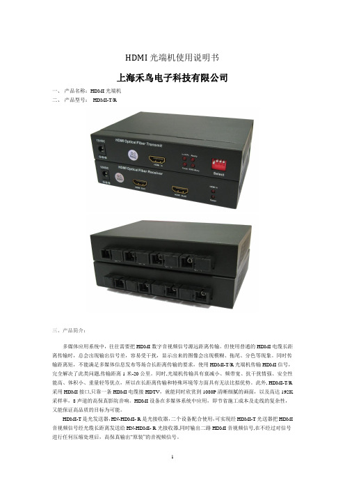
HDMI光端机使用说明书上海禾鸟电子科技有限公司一、产品名称:HDMI光端机二、产品型号:HDMI-T/R三、产品简介:多媒体应用系统中,往往需要把HDMI数字音视频信号源远距离传输。
但使用普通的HDMI电缆长距离传输时,总会出现输出信号差,容易受干扰,显示出来的图像会出现模糊、拖尾、分色等现象。
同时传输距离短,不能满足多媒体信息发布等场合长距离传输的要求,使用HDMI-T/R光端机传输HDMI信号,完全解决了此类问题,传输距离1米-20公里。
同时,光端机传输具有衰减小、频带宽、抗干扰情强、安全性能高、体积小、重量轻等优点,所以在长距离传输和特殊环境等方面具有无法比拟优势。
此外, HDMI-T/R 采用HDMI接口,只靠一条HDMI电缆接HDTV,就能同时欣赏到1080P清晰细腻的画面,以及高达192K 采样率,8声道的高保真影院音响。
HDMI设备在多媒体系统中应用,即节省施工成本及走线的复杂性,又能保证高品质的目标为可能。
HDMI-T是光发送器,HN-HDMI- R是光接收器,二个设备配合使用,可实现经HDMI-T光送器把HDMI 音视频信号经光缆长距离发送给HN-HDMI- R光接收器,同时输出二路HDMI音视频信号,在不经过对信号进行任何压缩处理后,高保真输出“原装”的音视频信号。
四、产品应用:地铁站台内高清视频多媒体信息发布系统列车站台内高清视频多媒体信息发布系统军事演习高清视频信号的远距离传输安防监控高清视频信号的远距离传输大型演出中高清视频信号传输各种高清视频的应该场合。
HDMI-T/R光端机完全兼容DVI接口信号。
采用HDMI转DVI电缆或转接头,就能实现DVI信号的传输。
五、使用方法:1、EDID学习功能:1.1 EDID介绍一个HDMI系统包括HDMI源端设备(带HDMI接口的显卡、高清播放机等)和HDMI接收端设备(显示设备,分配设备,传输设备等)两部分组成,DDC(DisplayDataChannel)通道用于HDMI源端和接收端之间交换一些配置信息。
高清数模视频处理器VP002工程机说明书

西安诺瓦电子科技有限公司
VP002 使用手册
高清数模视频处理器
西安诺瓦电子科技有限公司
声明
未经本公司书面许可,任何单位和个人不得擅自仿制、复制或抄译本手册部分或全部内容。不 得将本手册以任何形式(电子、机械、影印、录制或其它可能的方式)进行商业传播或用于任何商 业、盈利目的。
在使用设备前,请认真阅读本手册。手册中所提到的产品规格和咨询仅供参考,如有更新,恕 不另行通知。除非有特别约定,本手册仅作为使用指导,本手册中所有的陈述、信息等均不构成任 何形式的担保。
Ubiquiti Networks airFiber AF-5XHD快速入门指南说明书
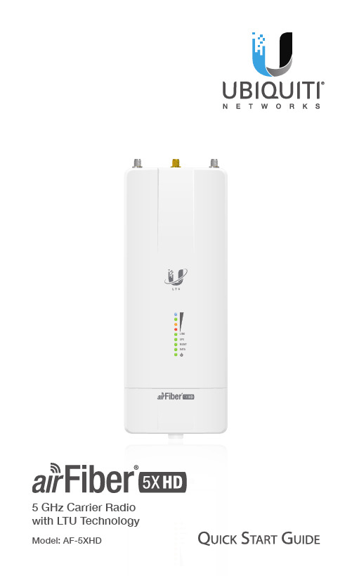
5 GHz Carrier Radio with LTU TechnologyModel: AF-5XHDGuide, available at: /download/airfiber Package ContentsairFiberAF-5XHD GPS Antenna Mount AntennaMetal Strap Zip Ties(Qty. 2)Universal Bracket IP67 Upgrade Kit (Vent and Gasket)Power Cord AF-5XHD Quick Start Guide TERMS OF USE: Ubiquiti radio devices must be professionally installed. Shielded Ethernet cable and earth grounding must be used as conditions of product warranty. TOUGHCable is designed for outdoor installations. It is the professional installer’s responsibility to follow local country regulations, including operation within legal frequency channels, output power, and Dynamic Frequency Selection (DFS) requirements.Antenna CompatibilityThe airFiber AF-5XHD radio is designed for use with the following airFiber X antenna models:• AF-5G23-S45• AF-5G30-S45• AF-5G34-S45The AF-5XHD can also operate with the following RocketDish™antenna models:• RD-5G30*• RD-5G34** Requires Universal Bracket (included) or AF-5G-OMT-S45 Conversion Kit (not included).Installation Requirements• Clear line of sight between airFiber radios• Clear view of the sky for proper GPS operation• Vertical mounting orientation• Mounting point:• At least 1 m below the highest point on the structure• For tower installations, at least 3 m below the top ofthe tower• Ground wires – min. 10 AWG (5 mm2) and max. length:1 m. As a safety precaution, ground the airFiber radio to grounded masts, poles, towers, or grounding bars.WARNING: Failure to properly ground yourairFiber radio will void your warranty.• (Recommended) 2 Outdoor Gigabit PoE surge protectors Note: For guidelines about grounding and lightningprotection, follow your local electrical regulatorycodes.• Outdoor, shielded Category 6 (or above) cabling and shielded RJ-45 connectors are required for all wired Ethernet connections.Hardware OverviewPort CoverLEDPanelExternal GPS - 45° on Chain 0: Connects to+ 45° onairFiber AntennaButtonManagement Port 10/100/1000 Mbps, secured Ethernet port for configuration. In-Band Management is enabled by default in the airFiber Configuration Interface. When In-Band Management is disabled, the MGMT port is the only port that can monitor, configure, and/or update firmware. This port can also be used to provide redundant PoE power.Reset Button To reset to factory defaults, press and hold the Reset button for more than 10 seconds while the device is powered on.Data Port Gigabit PoE port for handling all user traffic andpowering the device. Default IP address: 192.168.1.20Signal LEDsSignal 4 LED will light blue when on.Signal 3 LED will light green when on.Signal 2 LED will light yellow when on.Signal 1 LED will light red when on.Bootup to airOS When powering on, the Power, GPS, Link, and Signal 1-4 LEDs light on. Once the CPU code takes over, the GPS, Link, and Signal 1-3 LEDs turn off. The Signal 4 LED remains on to indicate the boot sequence is underway.Initializing airFiber Software When the airFiber application begins to boot under airOS®, the Signal 4 LED goes from solidly on to a 2.5 Hz flash. This continues until the AF-5XHDis fully booted.Signal Level Once fully booted, the Signal 1-4 LEDs act as a bar graph showing how close the AF-5XHD is to ideal aiming. This is auto-scaled based on the link range, the antenna gains, and the configured TX power of the remote AF-5XHD. Each Signal LED has three possible states: On, Flashing, and Off. All Signal LEDs would be solidly on in an ideal link. If the link has a 1 dB loss, the Signal 4 LED will flash; a 2 dB loss and the Signal 4 LED will turn off. The full bar graph LED states are shown below.0 = Off, 1 = On, F = FlashingAdditional LEDs* Short Flash (1:3 on/off cycle)Normal Flash (1:1 on/off cycle)Long Flash (3:1 on/off cycle)Installation OverviewWe recommend that you configure your paired AF-5XHD radios before site installation. The overview below summarizes the installation procedure, and the subsequent sections provide detailed installation information.• Connect the airFiber PoE Adapter to the Data port, and connect your computer to the MGMT port.• Configure the AF-5XHD.• Recommended: Install the IP67 Upgrade Kit (included) to prevent intrusion by water, dust, and insects.• Install a ground wire and mount the AF-5XHD on an airFiber X or RocketDish antenna.• At the installation site, install the airFiber X or RocketDish antenna with the mounted AF-5XHD radio (see the antenna’s Quick Start Guide for installation instructions).• Secure the ground wire and mount the GPS antenna.• Establish and optimize the RF link.Connecting Power over Ethernet1. Lift the release latch on the bottom of the AF-5XHD andslide the Port Cover off.http://192.168.2.20The login screen will appear. Enter ubnt in the Username and Password fields. Select your Country and Language. You must agree to the Terms of Use to use the product. Click Login.5. Click the Wireless tab.6. Configure the Basic Wireless Settings:a. For one AF-5XHD, select Master as the Wireless Mode.For the other AF-5XHD, select Slave as the WirelessMode.b. Enter a name in the Link Name field. This should be thesame on both the Master and the Slave.c. Select your Country.Note: U.S. product versions are locked to the U.S.Country Code to ensure compliance with FCCregulations.d. If needed, change the Channel Bandwidth, Frequency,Output Power (EIRP), Antenna Gain, and Max TXModulation settings. The Channel Bandwidth andFrequency should be the same on both the Master andthe Slave.7. Configure the Wireless Security:a. Select AES‑256 for the Security mode.b. Select PSK for the Authentication mode.c. In the Key field, enter a combination of alphanumericcharacters (0-9, A-Z, or a-z).Note: Only ASCII mode is supported.8. Click Save Changes.9. Configure each airFiber radio with a unique IP address forthe Data port:a. Click the Network tab.b. For both the Data IP Address and Management IPAddress options:-DHCP Have your router use DHCP reservation toassign a unique IP Address.-Static Change the IP Address, Netmask, and othersettings to make them compatible with yournetwork.c. Click Save Changes.wire to a grounded mast, pole, tower, or grounding bar.WARNING: Failure to properly ground yourairFiber radio will void your warranty.Note: The ground wire should be as short aspossible and no longer than one meter in length.*640-00338-05*640-00338-05Note: To mount the AF-5XHD to a RocketDish using the included Universal Bracket, see the Mount to a RocketDishMount to a RocketDish AntennaNote: If you are mounting the AF-5XHD on a RocketDishequipped with the AF-5G-OMT-S45 Conversion Kit, theUniversal Bracket is not needed. Refer instead to theMount to an airFiber X Antenna section for instructions. The RocketDish RD-5G30 antenna is shown in this section:1. Position the Universal Bracket over the back of the AF-5XHDMount the External GPS Antenna Locate a mounting point that has a clear view to the sky, and is above and as far away as possible from the AF-5XHD.1. Attach the GPS Antenna Mount to the pole using the Metal Strap, or attach it to a wall using the appropriate fasteners (not included).2. Place the External GPS Antenna on the mount.3. Secure the cable of the External GPS Antenna to the mount with a Zip Tie.Data port of thePOE port of the adapter.WARNING:Use only the included adapter, modelPOE‑24V‑5X‑HD. Failure to do so can damage theunit and void the product warranty.4. Connect an Ethernet cable from your LAN to the adapter’sLAN port.5. Connect the Power Cord to the adapter’s power port.1. Remove the Mounting Bracket from the adapter, place thebracket at the desired location, and mark the two holes. 2. Pre-drill the holes if necessary, and secure the bracketusing two fasteners (not included)., at the end of each link. Install the first surge protector within one meter of the airFiber Data port, and install the second surge protector at the ingress point of the location housing thedescribed in step 1.3. Check to see if a link is established. Ensure that the LinkLED is solidly lit green and the Signal LEDs of the Slave aredisplaying signal levels.4. Slave Aim the Slave at the Master to achieve the strongestsignal level on the Master.Note: Refer to the Signal LEDs section for details onthe signal values.Note: Maximum signal strength can best be achievedby iteratively sweeping through both azimuth andelevation.5. Master Aim the Master at the Slave to achieve thestrongest signal level on the Slave.6. Repeat steps 4 and 5 until you achieve an optimal link, withall four Signal LEDs solidly lit. This ensures the best possible data rate between the airFiber radios.7. Lock the alignment on both airFiber antennas bytightening all the nuts and bolts.8. Observe the Signal LEDs of each airFiber radio to ensurethat the values remain constant while tightening the nuts and bolts. If any LED value changes during the lockingprocess, loosen the nuts and bolts, finalize the alignment of each airFiber antenna again, and retighten the nutsand bolts.The Frequency, Output Power, Antenna Gain, and Cable Loss fields are provided to the professional installer to assist in meeting regulatory requirements.Specifications1 Full range depends on Ethernet cable length.2 Varies with firmware load and operational mode.3 After installation of IP67 Upgrade Kit (included).1 May vary depending on environmental conditions.2 Assuming 4096QAM (available with future firmware upgrade).* Depends on regulatory region. Online ResourcesWebsite Support Community Downloads Ubiquiti Networks, Inc.685 Third Avenue, 27th FloorNew York, NY 10017USA©2017-2018 Ubiquiti Networks, Inc. All rights reserved. Ubiquiti, Ubiquiti Networks, the Ubiquiti U logo, the Ubiquiti beam logo, airFiber, airOS, EdgeRouter, Rocket, RocketDish, TOUGHCable, and UNMS are trademarks or registered trademarks of Ubiquiti Networks,Inc. in the United States and in other countries. Apple and the Apple logo are trademarks of Apple Inc., registered in the U.S. and other countries. App Store is a service mark of Apple Inc., registered in the U.S. and other countries. Android, Google, Google Play, the Google Play logo and other marks are trademarks of Google LLC. All other trademarks are the property of their respective owners.AI091318。
- 1、下载文档前请自行甄别文档内容的完整性,平台不提供额外的编辑、内容补充、找答案等附加服务。
- 2、"仅部分预览"的文档,不可在线预览部分如存在完整性等问题,可反馈申请退款(可完整预览的文档不适用该条件!)。
- 3、如文档侵犯您的权益,请联系客服反馈,我们会尽快为您处理(人工客服工作时间:9:00-18:30)。
的F M4产 品 。
F M 系 列 MC U 基 于 AR M C o d e x — M 处 理 器 , 该 系 列
产 品 可提 供 高 达 2 0 0 MH z / 2 5 0 MI P S 的性 能 ,并 能 实现 传 感
器 、人机界面 ( HM1 )和家用电器等应用的超低功耗特性 ,
并 且信号 电平可 低至 1 . 8 V的 S PI 控制 器 ,3 4 8 B的可编 程
存 储 器 ,免 晶体 U SB操 作 , 以及 一 个 集 成 的 5 V 额 定 电 流
1 0 0 mA 的稳 压 器 。
Si l i c o n L a b o r a t o r i e s www . s i l a b s . c o n r
除了通常所需的片外器 件。C P 2 1 3 0器 件 包 括一 个 U SB 2 . 0 全 速 控 制 器 和 收 发 器 ,一 个 可 与 多 种 SP I 从 设 备 进 行 通 信
AD V 8 0 0 5视频信号处理器拥有一个灵活的数字 内核 , 允许设计 师把器件 配置 成多种不 同模式 ,包 括单通道 和双
在 通 信 接 口 方 面 , 则 支 持 包
括 串 行、C AN、U SB 、ห้องสมุดไป่ตู้以 太
器 时的 防漏 音功能 ( B D 3 7 0 3 4 F V) ,搭载 防漏 音功能 ,使
用 外 置 功 率 放 大 器 、 在 关 掉 整 机 电 源 时 产 生 的 漏 音 降 低 到 1 / 3 0以 下 , 可 有 效 防 止漏 音 ; 通过消减低频噪声实现高音 质,
支持 1 . 6 5 V ~ 5 . 5 V 的 额 定 电
压 , 其 嵌 入 式 闪 存 容 量 为
6 4 k B - 2 MB, 配 备 模 拟 接 口。
RF噪声消除功能 ,无需外置部件和新对 策 ,消除手机来 电
时 对音频设 备带来 的令人不 适的噪 声 ; 使 用 外 置 功 率 放 大
AD V 8 0 0 5 ,这 款 处 理 器 可 以在 S D( 4 8 0 i ) 、E D( 4 8 0 p ) 、 H D( 7 2 0 p 、1 0 8 0 i 和1 0 8 0 p )以及 U HD( 2 1 6 0 p ) 等 视 频
格 式之 间 进 行 上 下 转 换 。
高级 混合信 号 集成。C P 2 1 3 0桥接控 制器 是新设 计或 升级 现 有设计去包含 U S B功能 的各类嵌 入式应用的理想选择 , 这包括 U SB外设 、平板 电脑、手持式控制器和测试仪 、血 糖 监测仪、转接设备等 。 高集成度 的 CP 2 1 3 0控制器具 有片上功能 和外设 ,消
B D 3 7 0 3 3 F V 等 :音 频 处 理 器
E t 本 知名半导体制造商 ROHM ( 总部位 于 日本京都 ) 开发 出适 用于音 频设 备的音量 / 音质调 整产品 ,汽车音响用
音频处理器 “ B D 3 7 0 3 3 F V, B D 3 7 0 3 4 F V, B D3 7 0 6 8 F V” 、 A V接收器用音频处理器 “ B D3 4 7 0 1 K S 2 ” 。 主 要 特 性 :手 机 的 来 电 噪 声 抑 制 在 1 / 1 0以 下 ,搭 载
通 道 视 频 处 理 。处 理 器 集 成 两 个 片 内 HD MI 发 送 器 , 支 持
UHD视 频格式和 全部强制 和多种可选 3 D视 频分 辨率。此
外 ,A D V8 0 0 5还 集 成 6个 支 持 S D和 H D视 频 输 出 的 1 2 位视频 D A C。 为 了减 轻 同 步 视 频 信 号 所 需 开 销 ,AD V 8 0 0 5 可 以 把 来 自各 A D V 8 0 0 5视 频 信 号 处 理 器 的 多 重 输 出 视 频
AD I 推 出 一 款 超 高 清 ( U HD ) 视 频 信 号 处 理 器
口 ( S P I )总线提 供了完整的交钥匙解决方案 ,并且驱动程
序 支 持 Wi n d o ws 、 Ma c OS X和 L i n u x操 作 系 统 。 S i l i c o n L a b s的 新 型 CP 2 1 3 0 US B转 S P I 桥 接 控 制 器 在 紧 凑 的 4 mm x4 mm 封 装 中提 供 较 好 的数 据 吞 吐 量 、灵 活 的 配 置 和
②
艇慝
月度 新
CP 2 1 3 0 " 桥 接 芯 片
Si l i c o n L a b s推 出 高性 能 U S B转 SP I 桥接{ 牵制 器 产
品 ,它为 桥 接 通 用 串 行 总线 ( US B )主 机 和 串 行外 设 接
AD V8 0 0 5 :视 频 信 号 处 理 器
网通 信 等 多种 连 接 方 式 。F M4产 品基 于 Co d e x - M4处 理 器 , 有超过 1 4 0余 种 产 品 投 入 生 产 ,F M4融 入 了 D S P与 F P U 功 能 ,使 得 基 于 模 型 的 设 计 变 得 更 加 容 易 。该 系 列 产 品 配
流 同步到来 自外部源的参考 同步信 号。AD V 8 O 0 5含有一个
全 消费电子控 制 ( C E C) 主控 装置和音频 回授通道 接收器 , 最 多 能接 收 6个通 道 的 I S、S / P DI F 、直接 数 字 流 ( D SD )
和高 比特率 ( H B R) 音频 。A DI 的B l i mp OS D开发工具支持
全部 N a t u r e V u e视 频 信 号 处 理 器 。
Ana l og Devi ce s www. anal og, c om
F M系 列 : MCU
S p a n s i o n公 司推 出 了新开 发的 F M 系列 MC U,该 系 列 产品包括低功耗的 F M0 +产品线 ,如 F M3系列 何高性能