贝雷塔金诺曼Mynute J产品使用说明书
金色时代项目PRE-73 DLX微波电源说明书

W W W .G O L D E N A G E P R O J E C T .C O MIPRE-73 DLXINTRODUCTIONCongratulations on choosing the Golden Age Project PRE-73 DLX microphone preamplifier!The PRE-73 DLX is a one-channel vintage style microphone-, line- and instrument preamplifier. The signal path uses only discretecomponents like resistors, capacitors and transistors. The line and microphone input and the line output are transformer balanced, using three different transformers, each one optimized for its purpose.This is the way audio components were built before integrated circuits became available. The subjective sound quality delivered by vintage equipment is often prefered over the one delivered by modern units, a situation that is even more obvious now when music is recorded with cleansounding digital audio equipment.The circuit used in the PRE-73 DLX is similar to the preamp section in the classical 1073 module with a corresponding sound character that is warm, punchy, sweet and musical. These classic characteristics have been heard on countless recordings through the years and it is a versatile sound that works very well on most sound sources and in most genres. The essence of this sound is now available at a surprisingly low cost, making it available to nearly everyone.FEATURES- Vintage Style electronics. No integrated circuits in the signal path.- Maximum gain on the mic input is 80 dB, enough to handle passive ribbon mics with quiet sound sources. - Gain range on the Line input: -20 to + 10 dB.- Switchable impedance on the mic input, 1200 or 300 ohms, will change the tone of many mics. - Switchable phantom power and absolute phase.- A high impedance instrument input for any sound module, electric guitar or bass. - A simple but effective 4-step LED output level meter.- The output level control makes it possible to make fine gain adjustments and also to overload the main gain stage(s) for more character and then lower the signal to a suitable level before the output stage.- Combo XLR/TRS input jacks and separate output XLR and TRS jacks for flexible connections. - Insert jack for inserting EQ´s and other units.- External high power power supply to avoid interaction with the audio circuits and transformers. - A solid build quality that will last many years of normal use.The PRE-73 DLX has a number of improvement and new features compared to the PRE-73 MKII: - Tantalum capacitors in the signal path.- Selectable 1073-style high pass filter, 50, 80 , 160 and 300 Hz.- Output Attenuator -7, -14, -21 and -28 dB (located after the output transformer) allows overdriving the output stage and the output transformer for added character by lowering the output signal to a suitable level.- The circuit board is prepared for Carnhill Mic and Line transformer and high pass inductor.- The Insert jack can be switched in/out from the front panel. An internal jumper can select that the Insert jack always has an output signal.- Switchable 600 ohm Output Termination and Ground Lift on the back panel.- Selectable Active or Passive DI input and selectable input impedance in active mode, Hi Z or 100 kohm, by internal jumpers.- The DI signal can be selected to pass or bypass the mic input transformer by internal jumpers.- Relays are used to control internal switching for DI input, Phantom power, Mic Low Z, Insert and Phase for shorter circuit board signal paths. The relays are controlled by front panel switches.- Revised gain switch for added headroom. - Circuit board star grounding scheme.- Revised power supply with separate regulators for the audio circuits and relay and LED circuits.CIRCUIT DESCRIPTIONThe signal first enters an input transformer,one for the mic input and a one for the lineinput. The primary of the mic input trans-former has two windings that are either con-nected in series or in parallell which resultsin an input impedance of either 1200 Ohms or300 Ohms.The transformers are followed by two inputgain stages. For gains up to 50dB, only one of them is being used. For gains above 50dB, the second gain stage is inserted in the signal path. Both gain stages uses only three transistors each.The signal then goes to the Insert jack, the High Pass filter and the Output level potentiometer and from there on to the output stage. This stage again only uses three transistors, the last one in the chain is a hefty 2N3055 power transistor run in class-A mode, driving the output transformer that is followed by the stepped output attenuator (PAD).So, all in all, the complete signal chain only contains a maximum of nine active elements. Compare that to the big number of transistors that are usu-ally used in one single integrated circuit!USING THE PRE-73 DLXUsing a preamplifier is not rocket science. Here are some points though to help you getting the maximum out of the PRE-73 DLX:- Connect the cable from the power adaptor to the 24V AC connector at the back of the PRE-73 DLX. Power on the unit with the POWER switch at the front.- Connect your Mic and/or Line sources to the input XLR/TRS combo jacks at the back. A Mic and Line source can be connected at the same time,- Switching between Mic and Line input is simply done by setting the MIC/ LINE switch to one of the MIC or LINE positions.- Connect a cable from the XLR or the TRS output jack to the next unit in the chain. They are connected in parallel and carry the same signal. The outputs can feed both balanced and unbalanced inputs without any problems.- If you want the smallest amount of coloration, always set the OUTPUT level potentiometer at or close to maximum, the PAD to 0 dB and adjust the output level with the stepped LINE/MIC gain switch.- If you want more character, you can do any, or both of the following:1. Turn the OUTPUT level potentiometer counterclock-wise and increase the gain with the LINE/MIC switch. This will drive the input gain stage(s) harder and provoke more character from them.2. Engage the stepped output attenuator (PAD) and again increase the gain with the MIC/LINE switch. This will also drive the output stage and the output transformer harder and add character.- Engaging PAD at -14 dB is also useful if the input of the following unit has the -10 dBu semi-professional operating level. The standard operating level of the PRE-73 DLX is +4 dBu, the output level into a 600 ohm load will be about 1,23V when the “0” VU LED is lit when PAD is set to 0 dB.- Instruments can be connected to the active DI TRS input at the front panel. The DI uses a FET-buffer and has an input impedance of about 1,5 Mohm. Press the DI switch to engage this input. The DI input works in the MIC positions of the gain switch. Mic and Line sources at the back can remain connected.The output of the DI circuit is sent through the mic input transformer.- Engage the +48V phantom power for any mic that needs it. It is a good procedure to always disengage the phantom power and wait for about 10 seconds before unplugging the mic.- When the LOW-Z switch is engaged, the input impedance of the Mic input drops from 1200 Ohms to 300 Ohms. This will change the tone of many micro-phones and will give you one more soundshaping option. It also increases the level, which is normal.- The PRE-73 DLX has a inductor based high pass filter with a roll off of 18 dB/ octave. This is a very useful tool to remove excess bass energy.- The phase switch simply reverses the phase by reversing the wires from the secondary winding of the output transformer. Reversing the phase of the signal is useful on a number of occasions, one example is phase reversing the the lower mic of a snare drum to make it sum in phase with the upper mic.- There is an unbalanced Insert jack located at the back panel where you can insert Equalizers and other external effect units that has an operating levelof about -18 dBu. The Insert is engaged with the INSERT switch on the front panel. Send is on “tip” and return on “ring”.- The output transformer used in the PRE-73 DLX is made for having an ideal load of about 600 ohm. The input impedance of most modern units is 10 kohm or more. The PRE-73 DLX has a 600 ohm output termination switch locatedat the back panel. Engaging the switch terminates the output transformer with a resistor to bring down the load to about 600 ohms. This switch should normally be engaged if you are connecting the PRE-73 DLX to a modern unit but you can also choose not to engage the switch. This will lift the high end frequency response slightly which can sometimes be a good thing.- There is a Ground Lift switch on the back panel that lifts the internal ground from the cabinet. If the unit is mounted in a rack together with other units and you experience ground loop problems, try engaging it.CUSTOMIZING THE PRE-73 DLXThere are several functions in the PRE-73 DLX that can be customized by the user. Remove the top plate of the unit and then follow the instructions below. Feel free to experiment with the different small tonal changes that these options can provide.1. To change the input impedance of the active DI input to 100 kohmLocate the jumper JP3 just behind the DI TRS jack. Relocate the jumper so that it connects both pins of JP3.2. To change the DI input from an active one to a passive oneThis option will feed the signal from the DI input directly to the mic input transformer or to the first gain stage if option no 3 is used.Locate the “DIout” socket about 10cm/4” from the front panel at the left edge of the circuit board. Remove the connector from the socket and connect it to the “DI pass out” socket located just behind the power switch.Option no 1 can NOT be used at the same time as option no 2!3. To change the DI from not passing through the mic input transformerThis option will feed the signal from the DI input directly to the gain stage.- Locate the “DIpreXF” socket just behind the middle of the MIC and LINE XLR inputs. Remove the connector and connect it to the “DIpostXF” socket located in front of the mic input transformer which is the one to the left in the middle of the circuit board.- Locate the “DIpre” jumper located to the right of the “DIpostXF” socket. Remove the jumper and install it at the “DIpost” jumper located to the right of the “DIpreXF” socket.4. To cut the output signal to the INSERT jack when insert is not activated Locate jumper “INSout” just behind the middle of the LINE input XLR and the INSERT TRS jack. Remove the jumper.The circuit board of the PRE-73 DLX is prepared for Carnhill transformers and inductors. If you did not buy your unit with these options, they can be fitted whenever you want to do so. The work can be made by the distributor in your area or you can do it yourself if you have soldering experience. Please note though that the warranty will be void if work has been made on your unit by anyone else than one of our Distributors.The Carnhill parts can be bought in our webshop or through our Distributors. WARRANTYThe PRE-73 DLX is built to last. But as in any electronic device, components can break down.There is a 1,5A, fast blow fuse located inside the unit. If the unit dies, please check this fuse. If it has blown, replace it with a new one. You can also try with another 24V AC adaptor if you have one available.If this doesn´t help, or if the unit has another problem, it will need repair and you should then contact the reseller where you bought the unit.The warranty period is decided by the Distributor for your country. The Dis-tributor will support Golden Age Project resellers and end users with repairs and spare parts.REGISTRATIONYou are welcome to register your unit at: ---------------------------I would like to thank you for chosing the PRE-73 DLX!I hope it will serve you well and that it will help you in makingmany great sounding recordings.Yours,Bo MedinCreate music– Be happy!W W W.G O L D E N A G E P R O J E C T.C O M。
NEWMAN MTA系列 即热式电热水器 产品说明书
产品简介尊敬的用户,非常感谢您使用纽曼即热式电热水器产品,在您准备安装及使用本产品之前,请先仔细阅读本说明书.产品特点:1、采用优质英格莱800第四代不锈钢发热元件,真正水电隔离,配备多重安全保护装置,充分确保您可无忧 及尽情的享受本产品给您带来的愉悦心情2、功能:本产品设计超低水压启动,保证您在使用时不会由于水压太低而影响本产品的使用3、服务:质量实行国家“三包”政策,购机即可享受免费上门安装、免费整机一年保修、终身维护以下情况不能享受或可有偿享受本公司的服务:1、不按说明书安装及操作不当造成的2、自行拆卸、改装或维修的3、超过保修期限的4、保修卡记录与实物不符或经涂改的5、保修卡或购买凭证均已丢失的二、客户使用说明6. 热水器各部分名称及功能87.使用及调整方法8. 加热功率入水量及温升之关系9. 故障维修及规格9 9 10铁锤花洒火线L:红色铜芯线安装步骤说明:1、将热水器孔之间距离量测,用铅笔在安 装体上作好标识2、用电钻在已作好标记的地方钻孔3、将胶粒放入钻好的孔中,用螺丝刀把固 定螺丝锁好4、将热水器背面孔位对准固定螺丝的位置,摆放好即可出水口温度显示二、客户使用说明7、使用及调节方法使用方法:1、打开水阀,当热水器出口处有水流出时.再接通电源。
2、按动机身上的电源开关,稍等三至五秒, 即有热水流出调节方法:1、当水温过高或过低时,可通过机身上的按键来增大或减小功率,达到调节水温的 目的。
2、也可通过调整节流阀控制水流 量的大小来达到调节水温的目的,水 流量越大,水温则越低。
8、加热功率与入水量及温升之关系技术参数及规格:10、防护功能(A)过热保护功能:为防止出水温度过高,而导致顾客在使用时皮肤受到伤害,故本产品最高温度限制为65度,当达到此温度时,产品会自动停止加热,直到出水温度低于45度左右时再重新自动加热(B)内置及外置式漏电保护:内置:超速敏感的过流感应线圈,当内部出现故障,导致产品漏电,该功能会在0.01秒的时间内自动切断工作电流.外置:超强的隔电墙与空气开关配套使用,起到保护安全的双保险作用.(C)防干烧保护功能:全自动电脑监控及检测措施,防止由于各种原因而出现的干烧现像,在保护您的同时,也更好的巩固了产品的使用寿命.11、注意事项1、用户不得自行安装本产品,必须由指定人员进行安装2、安装本产品的用电环境需达到本产品的说明要求,且要有可靠接地装置。
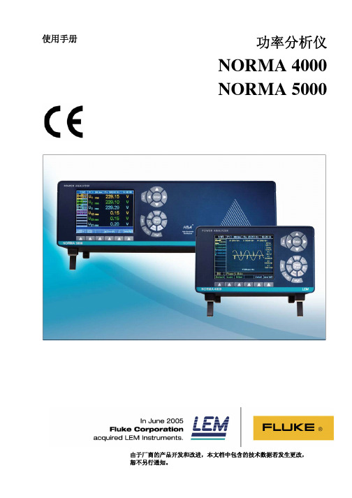
norma4K5K使用手册
雷诺尔JJR软起说明书

JJR系列软起动器用户手册目录安全注意事项⋯⋯⋯⋯⋯⋯⋯⋯⋯⋯⋯⋯⋯⋯⋯⋯⋯⋯⋯⋯⋯⋯⋯⋯⋯⋯⋯⋯⋯⋯⋯⋯⋯安装准备⋯⋯⋯⋯⋯⋯⋯⋯⋯⋯⋯⋯⋯⋯⋯⋯⋯⋯⋯⋯⋯⋯⋯⋯⋯⋯⋯⋯⋯⋯⋯⋯⋯⋯⋯使用及环境条件⋯⋯⋯⋯⋯⋯⋯⋯⋯⋯⋯⋯⋯⋯⋯⋯⋯⋯⋯⋯⋯⋯⋯⋯⋯⋯⋯⋯⋯⋯⋯⋯1.概述⋯⋯⋯⋯⋯⋯⋯⋯⋯⋯⋯⋯⋯⋯⋯⋯⋯⋯⋯⋯⋯⋯⋯⋯⋯⋯⋯⋯⋯⋯⋯⋯⋯⋯⋯⋯典型应用简介⋯⋯⋯⋯⋯⋯⋯⋯⋯⋯⋯⋯⋯⋯⋯⋯⋯⋯⋯⋯⋯⋯⋯⋯⋯⋯⋯⋯⋯⋯⋯⋯JJR 系列软起动功能⋯⋯⋯⋯⋯⋯⋯⋯⋯⋯⋯⋯⋯⋯⋯⋯⋯⋯⋯⋯⋯⋯⋯⋯⋯⋯⋯⋯⋯2.购入检查⋯⋯⋯⋯⋯⋯⋯⋯⋯⋯⋯⋯⋯⋯⋯⋯⋯⋯⋯⋯⋯⋯⋯⋯⋯⋯⋯⋯⋯⋯⋯⋯⋯⋯3.安装⋯⋯⋯⋯⋯⋯⋯⋯⋯⋯⋯⋯⋯⋯⋯⋯⋯⋯⋯⋯⋯⋯⋯⋯⋯⋯⋯⋯⋯⋯⋯⋯⋯⋯⋯⋯4.电路连接⋯⋯⋯⋯⋯⋯⋯⋯⋯⋯⋯⋯⋯⋯⋯⋯⋯⋯⋯⋯⋯⋯⋯⋯⋯⋯⋯⋯⋯⋯⋯⋯⋯⋯主回路⋯⋯⋯⋯⋯⋯⋯⋯⋯⋯⋯⋯⋯⋯⋯⋯⋯⋯⋯⋯⋯⋯⋯⋯⋯⋯⋯⋯⋯⋯⋯⋯⋯控制端子⋯⋯⋯⋯⋯⋯⋯⋯⋯⋯⋯⋯⋯⋯⋯⋯⋯⋯⋯⋯⋯⋯⋯⋯⋯⋯⋯⋯⋯⋯⋯⋯控制电路端子连接⋯⋯⋯⋯⋯⋯⋯⋯⋯⋯⋯⋯⋯⋯⋯⋯⋯⋯⋯⋯⋯⋯⋯⋯⋯⋯⋯⋯主回路连接⋯⋯⋯⋯⋯⋯⋯⋯⋯⋯⋯⋯⋯⋯⋯⋯⋯⋯⋯⋯⋯⋯⋯⋯⋯⋯⋯⋯⋯⋯⋯基本电路框图和端子⋯⋯⋯⋯⋯⋯⋯⋯⋯⋯⋯⋯⋯⋯⋯⋯⋯⋯⋯⋯⋯⋯⋯⋯⋯⋯⋯5.键盘及显示说明⋯⋯⋯⋯⋯⋯⋯⋯⋯⋯⋯⋯⋯⋯⋯⋯⋯⋯⋯⋯⋯⋯⋯⋯⋯⋯⋯⋯⋯⋯⋯6.数据的设定⋯⋯⋯⋯⋯⋯⋯⋯⋯⋯⋯⋯⋯⋯⋯⋯⋯⋯⋯⋯⋯⋯⋯⋯⋯⋯⋯⋯⋯⋯⋯⋯⋯7.通电运行⋯⋯⋯⋯⋯⋯⋯⋯⋯⋯⋯⋯⋯⋯⋯⋯⋯⋯⋯⋯⋯⋯⋯⋯⋯⋯⋯⋯⋯⋯⋯⋯⋯⋯8.保护显示说明⋯⋯⋯⋯⋯⋯⋯⋯⋯⋯⋯⋯⋯⋯⋯⋯⋯⋯⋯⋯⋯⋯⋯⋯⋯⋯⋯⋯⋯⋯⋯⋯9.软起动控制模式⋯⋯⋯⋯⋯⋯⋯⋯⋯⋯⋯⋯⋯⋯⋯⋯⋯⋯⋯⋯⋯⋯⋯⋯⋯⋯⋯⋯⋯⋯⋯限流型⋯⋯⋯⋯⋯⋯⋯⋯⋯⋯⋯⋯⋯⋯⋯⋯⋯⋯⋯⋯⋯⋯⋯⋯⋯⋯⋯⋯⋯⋯⋯⋯⋯电压控制型⋯⋯⋯⋯⋯⋯⋯⋯⋯⋯⋯⋯⋯⋯⋯⋯⋯⋯⋯⋯⋯⋯⋯⋯⋯⋯⋯⋯⋯⋯⋯软停车曲线⋯⋯⋯⋯⋯⋯⋯⋯⋯⋯⋯⋯⋯⋯⋯⋯⋯⋯⋯⋯⋯⋯⋯⋯⋯⋯⋯⋯⋯⋯⋯不同起动方式的电流波形比较⋯⋯⋯⋯⋯⋯⋯⋯⋯⋯⋯⋯⋯⋯⋯⋯⋯⋯⋯⋯⋯⋯⋯10.结构特点⋯⋯⋯⋯⋯⋯⋯⋯⋯⋯⋯⋯⋯⋯⋯⋯⋯⋯⋯⋯⋯⋯⋯⋯⋯⋯⋯⋯⋯⋯⋯⋯⋯附表一应用场合⋯⋯⋯⋯⋯⋯⋯⋯⋯⋯⋯⋯⋯⋯⋯⋯⋯⋯⋯⋯⋯⋯⋯⋯⋯⋯⋯⋯⋯⋯⋯⋯JJR1000系列二次接线图⋯⋯⋯⋯⋯⋯⋯⋯⋯⋯⋯⋯⋯⋯⋯⋯⋯⋯⋯⋯⋯⋯⋯⋯⋯⋯⋯⋯⋯JJR2000系列二次接线图⋯⋯⋯⋯⋯⋯⋯⋯⋯⋯⋯⋯⋯⋯⋯⋯⋯⋯⋯⋯⋯⋯⋯⋯⋯⋯⋯⋯⋯警告!只有专业技术人员允许安装JJR。
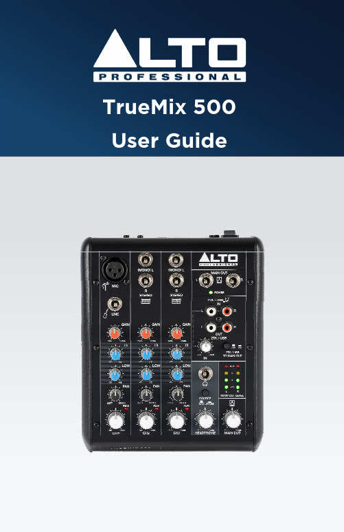
TrueMix 500商品说明书
(1.4) Sound Level
Permanent hearing loss may be caused by exposure to extremely high noise levels. The U.S. Occupational Safety and Health Administration (OSHA) has specified permissible exposures to certain noise levels. According to OSHA, exposure to high sound pressure levels (SPL) in excess of these limits may result in hearing loss. When using equipment capable of generating high SPL, use hearing protection while such equipment is under operation.
(2.2) Setup Scenario........................................................................................ 7
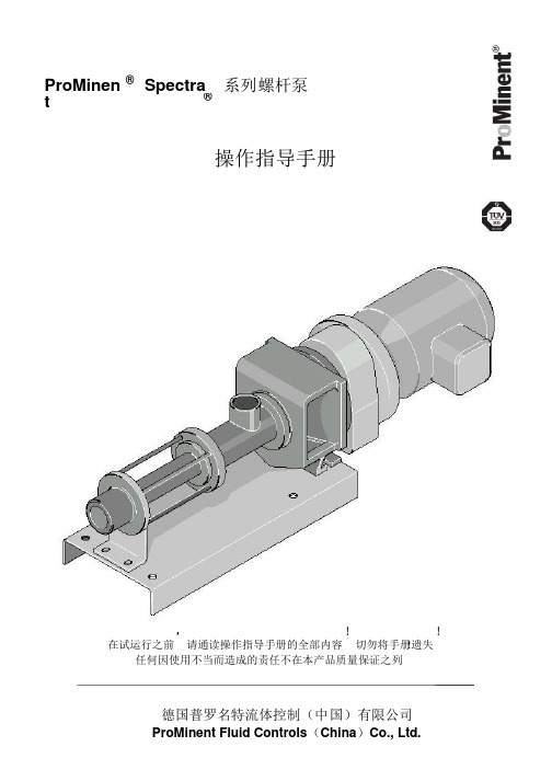
螺杆泵中文说明书-普
3.1 包装及运输............................................................................................................................................6 3.2 储存........................................................................................................................................................7
8 故障的发现及排除 ...................................................................................................................15
8.1 故障表..................................................................................................................................................15 8.2 如何根据出现的故障来寻找产生的原因 ..........................................................................................15
美国ZOLL_M-series除颤监护仪操作培训

除颤手柄及多功能电极片放置的位置
除颤导电膏
在每个除颤板的电极表面上使用适量的导电凝胶(建议C字型涂抹),然后将两个除颤板的电极表面放在一 起摩擦,使导电凝胶分布均匀。
注意:超声耦合剂不能代替导电膏,并且耦合剂会阻隔电流传递,影响除颤效果!
除颤导电膏
30焦耳检测和机内放电。
பைடு நூலகம்
日常维护
充电电池维护
新电池使用前要求做“三充三放”,激活电池活性,前三次充电必须充12 小时,电池常规充电时间约4小时
日常使用时,电池每月做一次完全充放电 电池不能过度放电 常规充电时,不建议长时间对电池充电,电池充满电后即可拔掉电源 电池不用,储藏超过90天可能会损坏,建议每月取出做一次完全充放电
旋到除颤档,按下同步按钮 使用3导心电或多功能电极片监测心电 能量选择,充电,持续按着放电按钮, 直到识别到下一个R波时才放电。
同步电复律-SYNC
一、选择到除颤模式,连接ECG或 者多功能电极片到患者胸壁,屏幕 上出现ECG信号
二、点击屏幕下方的同步开 关按钮,开启同步功能
三、同步功能开启后,每个 ECG波形的R波被标记
影响除颤效果的因素
导电膏的使用 患者皮肤汗液、水分、胸毛或其他异物的清除和清洁
影响除颤效果的因素
多功能电极片与除颤板的比较优势 除颤板的位置 除颤板与患者的接触良好程度 除颤板的按压力量 操作者对高压、大电流放电的恐惧
注:除颤板容易引起使用不当, 影响除颤的效果和成功率,建 议尝试使用多功能电极片进行 除颤
焦耳,逐步递增,Class II a推荐。 最新国际复苏指南推荐,对房扑和其它室上速,双相波成人首次
海南曼姆全系产品介绍说明书
Heinemann®GJ1P Series Circuit BreakersDESCRIPTIONOptional Low-Voltage Shunt for Current MeteringEaton Corporation’s Cutler-Hammer series of Heinemann GJ1P breakers offer high quality circuit protection for DC applications from 100 to 1200 Amperes.Their precisely tailored time delays and ability to interrupt high currents makes them ideally suited for critical applications. On overloads exceeding 1000 – 1400% of rating, there is no intentional time delay and the breaker interrupts currents of as much as 25,000 A at 65V DC.An optional shunt (25 or 50millivolt full scale) permits metering of current. Since the shunt output is low voltage,light-gauge wiring can be used from shunt to meter.Indication may be displayed inpercent, watts, safe/danger or other dial calibrations. In addition, the busbar is available in two versions:Standard Size and Reduced Size. Contact your Eaton Sales Representative for more information.Precision Current Equalization (PCE) Circuit BreakersGJ1P breakers rated 250 to1200 A are built in parallel construction. Conventional parallel pole breakers can experience uneven current distribution because of variations in internalresistances. This condition can result in nuisance tripping since the higher current in one parallel branch has the same effect as an overload on the sensing element in that branch. Proprietary Precision Current Equalization (PCE)circuit breakers, on the other hand, allow for differences in internal resistances byautomatically distributing the current equally through the parallel current sensing elements, minimizing the danger of nuisance tripping.The UL listed series GJ1P (UL489) models are available in a choice of fast, medium or slow response times to accurately match load conditions. They can be ordered in “series trip ”, “mid-trip ” and “switch only ”constructions and are available front- or back-mounted, front- or back-connected, with optional auxiliary switches for signaling.HYDRAULIC-MAGNETIC BENEFITSThe magnetic/hydraulic load-sensing and time delaymechanisms used in GJ1P breakers are insensitive to changes in ambient or enclosure temperature.Therefore, GJ1P circuitbreakers are suited for service conditions encountered in telecommunications,transportation, air conditioning and other outdoor or “heat-loaded ” equipment.SPECIFICATIONSStandard Current Ratings:100, 125, 150, 175, 200, 225,250, 300, 350, 400, 450, 500,600, 700, 800, 900, 1000,1100, 1200 A.Standard Maximum Voltages:160V DC up to 700A65V DC from 701 to 1200A Breakers will be labeled with standard maximum (UL) voltage unless otherwise specified.Special Current Ratings:Any integral rating between 100and 1200 A DC. Consult factory for ordering information and metering shunt restrictions.Interrupting Capacities:UL Listed:10,000 A @ 160V DC 25,000 A @ 65V DC Non-UL:14,000 A @ 160V DC.Operating Temperature Range:-40°C to +85°C.Approximate Weight:1-pole (100-225A) 1.13kg (2.5lbs)2-pole (250-400A) 2.27kg (5lbs)3-pole (450-700A) 3.40kg (7.5lbs)4-pole (701-800A) 4.54kg (10lbs)5-pole (801-1000A) 5.67kg (12.5lbs)6-pole (1001-1200A) 6.80kg (15lbs)Weight may vary based on shunt and busbar.APPROVALSUL Listing:GJ1P breakers are UL listed per UL489. For CSA certification,consult application engineering.Description . . . . . . . . . . . . . .2Specifications . . . . . . . . . . . .2Approvals . . . . . . . . . . . . . . .2Time Delay Characteristics . . .3Dimensions . . . . . . . . . . . .4-5How to Order . . . . . . . . . . .6-7Additional Products. . . . . . . . .8TABLE OF CONTENTS PageHEINEMANN ®CIRCUIT BREAKERSGJ1P Series Circuit Breakers(100-1200 Amperes DC)2Heinemann is a registered trademark of the Eaton Corporation, Commercial Controls Business Unit.100150.01.001.1110100100010,000200300400500600700800900100011001200125C u rv e 1C u rv e 2C u rv e 3Current – Percent of Ampere RatingT r i p T i m e – S e c o n d sDC CURVES100150.01.001.1110100100010,000200300400500600700800900100011001200125Current – Percent of Ampere RatingT r i p T i m e – S e c o n d sINSTANT DELAY DC CURVE PPERCENT OF RATED CURRENT VS. TRIP DELAY AT 25ºCTIME DELAYCHARACTERISTICSTime delay, in all models,is inversely proportional to the magnitude of the overload, adjusting automatically to limit transient power to the load. On overloads exceeding 1,000 –1,400%, the circuit breaker trips without any deliberately imposed delay.Curve 1.Standard time delayis furnished unlessanother optional delay is specified. It is thepreferred characteristic for use where the load is composed of both resistive and inductive components.Curve 2.Medium time delayis for general usein mixed (inductive and resistive) circuits where the breaker rating is matched to the current carrying capacity of the mains.Curve 3.Short time delaypermits a very brief delay period before tripping.Curve P .Non-time delay breakersare available forapplications which cannot tolerate even brief transient overloads.These breakers have no time delay mechanism other than that imposed by the coil self-inductance and the inertia of the mechanism.Tripping specificationsThe time delay curves depict breaker response time vs. percent of rated load with no preloading.The function is plotted at an ambient temperature of 77°F (25°C) with the breaker in a vertical or wall-mounted position.Series GJ1P circuitbreakers will carry 100%of rated load continuously.Both time delay and non-time delay breakers may trip between 101%and 125% of rated load,and must trip at 125%and above.3% (sec)Delay 100%125%200%400%600%800%1000%Delay Max.1no trip 1100150206 1.7.065Delay Min.1no trip 110224 1.1.01.008Delay Max.2no trip 110153.8.28.055Delay Min.2no trip 12 2.5.5.18.01.008Delay Max.3no trip 10.8.19.08.047.038Delay Min.3no trip.44.13.03.015.01.008STANDARD FRONT-CONNECTED CONSTRUCTIONWire Range #6 to 250 MCM74.59(2.938)76.20(3.000)Aux. Terminals, Male Type Molex 02-09-2101, Model 1190-T(See Illustrations for Combinations)Shunt Terminals, Female TypeMolex 02-09-1101, Model 1189-T37.69(1.484)42.84(1.687)0.99 (0.390)71.42(2.812)#10-32 Inserts (4 Places)38.10(1.500)19.05(0.750)19.05(0.750)6.35 ± 0.38(0.250 ± 0.156)6.35 ± 0.38(0.250 ± 0.156)Panel Mounting Hole Distance for #10-32LINELOAD 75.38(2.968)5.53(0.218)59.91(2.359)32.13(1.266)5.53(0.219)“D ” Type Terminals as Shown180.97(7.125)41.27(1.625)4.74(0.188)58.67(2.313)41.27(1.625)41.27(1.625)263.52(10.375)29.36(1.156)7.14(0.281)78.56(3.094)59.13(2.328)28°±5°32°±5°ONOFFSee Optional Terminal ConfigurationWire Range #6to 250 MCM41.27(1.625)36.49(1.437)38.10(1.500)100 – 22 A250 – 400Width dimensions are as follows:100 – 225 38.1 (1.5)250 – 400 A 76.2 (3.0)450 – 700 A 114.3 (4.5)701 – 800A 142.4 (6.0)801 – 1000A 190.5 (7.5)1001 – 1200A228.6 (9.0)28.95(1.141)46.40(1.828)22.22(0.875)Fastener Mounted ThisSide of Bus Plate,Terminals are Front-Connected and Unit is Rear-Mounted.Fastener Mounted This Side of Bus Plate, Terminalsare Back-Connected and Unit is Panel-Mounted.60.32(2.375)7.92(0.312)3/8-16UNC -2B (4 per Unit)38.10(1.500)225.43 (8.875)Center to CenterOptional Terminal ConfigurationsHEINEMANN ®CIRCUIT BREAKERSGJ1P Series Circuit BreakersDIMENSIONSDimensions are given here only as a preliminary guide to specifying. Final engineeringdrawings should be made from the latest Heinemann drawings. Contact Customer Service Center.Tolerance:±0.79 (0.031) except where noted. For metric threads, contact Customer Service Center.DIMENSIONS APPROXIMATE IN MM (INCHES)431.75(1.250) Min.41.65(1.641) Max.19.05(0.750)7.51(0.297)7.51(0.297)7.51(0.297)16.66(0.656)Typ.29.36(1.156)29.36(1.156)48.41(1.906)48.41(1.906)67.46(2.656)67.46(2.656)38.10(1.500)38.10(1.500)38.10(1.500)38.10(1.500)19.05(0.750)19.05(0.750)19.05(0.750)22.23(0.875) Min.321.31(12.65) Max.78.96(3.109)Min. Typ.5.15(0.203)Dia. Typ.C100 – 225 A Ratings 226 – 400 A Ratings401 – 700 150A RatingsBA106.75(4.203)Typ.C LC L C L FRONT MOUNTING PANEL AND SUPPORT BRACKET115.08(4.531)76.98(3.031)38.1(1.500)38.1(1.500)71.42(2.912)5.94(0.234)Ref.5.15(0.203)Typ. Dia.65.02(2.562)59.13(2.328)(3-Pole)3PoleC L C L C L Holes Required When Breaker Is Front-Mounted2Pole1PoleAB C (2-Pole)(1-Pole)38.88(1.531)19.43(0.765)Mounting kits containing clips, brackets and necessary hardware and instructions are available (consult factory).009-18234 100 – 225 A 1.5 (1-pole wide)009-18235 250 – 400 A 3 (2-pole wide)009-18232 450 – 700 A 4.5 (3-pole wide)For 701-1200A devices, contact your Eaton Sales Representative for mounting kit part numbers.See Step (2)See Step (5)BACK MOUNTING CIRCUIT BREAKERBack mounting circuit breaker mounting instructions 1. Position circuit breaker to support brackets.2. Place mounting bracket in recess on front top portion of circuit breaker.3. Install four (4) #10-32 by 3-1/4" long screws through holes in mounting bracket and support structure.4. Install lock washer and nut on each of the screws and tighten.5. Place mounting bracket on front lower portion of circuit breaker.6. Install two (2) #10-32 by 5/8" screws through holes in mounting bracket and support structure.7. Repeat step 4.5DIMENSIONS APPROXIMATE IN MM (INCHES)NOTE: Standard size busbar is shown above. For the reduced size busbar, contact your Eaton Sales Representative for mounting dimensions.Series PrefixGJ1PSwitch (No Coil)Series Trip w/SPDT Aux. SwitchSeries Trip Series Trip and Mid-Trip Series Trip, Mid-Trip and SPST Alarm SwitchTerminal Location Back FrontInternal Circuit Metering ShuntNo Shunts Metering Shunt Metering ShuntB HCodeLocationInternal CircuitCodeDescriptionShuntCode—25mV 50mVP M N0-2-3-98-99-Series Prefix GJ1PTerminal LocationBInternal Circuit3-Metering ShuntPAdd each appropriate Number or Letter …HEINEMANN ®CIRCUIT BREAKERSGJ1P Series Circuit BreakersHOW TO ORDER — Series GJ1PTo determine your Complete Catalog Number , you must start with appropriate Series Prefix and add the appropriate Code Letters and/or Numbers as in the example below:SELECTION TABLE61Multi-pole construction – Consult factory.An auxiliary switch, if supplied, will be located in the right pole space. If the auxiliary switch is supplied in a breaker which has a metering shunt, it will be single-pole single throw (SPST). The single-pole double throw (SPDT) auxiliary switch can be supplied only in a breaker without a metering shunt.2Cannot be used on breaker containing metering shunt.3Only for breakers rated in excess of 250 A. Breakers up to 250 A without meteringshunt are available as standard GJ1 type breakers. Please consult Series GJ catalog.MarketUL-489TerminalsSolderless Connector Bus Bar ConnectionStandard Current Ratings 1AmpereTrip Curve 1123P0 – 1200(Add 0 before amp rating if less than 1000A.Example: 0700)-01-02-03-0PDescriptionCodeDEDUStandardCodeCurveCodeComplete Catalog Number: GJ1PB3-PEDU0700-02Terminal ConfigurationEUS/European ApprovalDUStandard Current Ratings 10700Trip Curves 1-024Add 0 before amp rating if less than 1000. For example: a 700A rating would bedesignated as 0700.The width of the breaker is determined by the current rating:100 – 225 A 1.5” (1-pole wide)250 – 400 A 3” (2-pole wide)450 – 700 A 4.5” (3-pole wide)701 – 800A 6” (4-pole wide)801 – 1000A 7.5” (5-pole wide)1001 – 1200A 9” (6-pole wide)5See page 3 for time delay characteristics and trip curve information.7© 2001 Eaton Corporation All Rights Reserved Printed in USAForm No. BR5401SE0002A / CSS 65322June 2001Commercial ControlsFor the Widest Selection of Circuit Protection, from 0.01 to 1200 Amperes, Look to Eaton.。
MC虎鉗說明書说明书

ºӊ̨ډཌٙ৷ܓၾኬ͍ᒟᅻޫਂ֛ʂ၍Փf
The height and the guide block side of every vise are
all made with full control.
H-ˉʂʮࢨࠢܓ0.02ˇאf
L-ˉʂʮࢨࠢܓ0.02ˇא
H- Dimension tolerance 0.02
L- Dimension tolerance 0.02 or less. or less.
H L
࢙࠽ Allowance
No.
Ꮸݟධͦ InspectiSS
1
4
ཌɹࠦ࿁ֵ̨͉ࠦኬ͍ᒟᅻʘ̻Бܓ
1. Parallelism of guide block side of body bottom face and fixed jaw clamp force. ཌɹࠦ࿁ਗࠦʘٜۧܓ
MODEL A B C D E F G H
I
J J1 K L
M
153 JQV-160L 161 635 536 99 94 86 60 100 160 355 535 18 145 159 153 JQV-160XL 161 800 701 99 94 86 60 100 160 520 695 18 145 159 153 JQV-160LL 161 985 886 99 94 86 60 100 160 705 800 18 145 159
0.01
0.015
2. Squareness of fixed jaw clamp face and
0.015
0.03
2
5
jaw slide way.
ᕐਉࠦ࿁ਗࠦʘٜۧܓ
Redapt DP-E系列增强安全呼吸泡泡(金属)商品说明说明书

Increased safety (Exe) breather drains (metallic) - DP-E SeriesDimensionsRedapt DP-E series of Exe breather drains provide a method of preventing moisture build-up within a hazardous area approved enclosure whilst ensuring the integrity and Ex approval of the installation is maintained.They allow for air within an enclosure to breathe with the surrounding atmosphere helping to prevent condensation and any potential damage to sensitive electric/electronic equipment housed within. All whilst maintaining an IP66 rating of the enclosure it is installed in.Designed for hazardous area applications, Redapt’s DP-E series of breather drains are certified to protection concept Exe “Increased Safety” for use in Zone 1 and Zone 2 applications. Also certified Ex tb “dust tight” for use in Zone 21 & 22 applications.Materials• Brass CZ121• 316 stainless steel • AluminiumPlating options• Electroless nickel • Zinc• Others on applicationThreadforms• Metric • NPTType DP-ESize A/F Overall length (A)Thread length (B)M2028.6023.00 (min.)10.00 (min.)M2534.9023.00 (min.)10.00 (min.)M3241.3023.00 (min.)10.00 (min.)½" NPT 28.6028.00 (min.)15.00 (min.)¾" NPT 34.9028.00 (min.)15.00 (min.)1" NPT41.3028.00 (min.)15.00 (min.)T echnical specificationsCode of protection categoriesATEX: I M2/II 2 GD, Ex e I/II Mb Gb, Ex tb IIIC Db IECEx: Ex e I/IIC Mb/Gb, Ex tb IIIC DbCSA: Ex eb IIC Gb IP66 Cl I Zn 1 AEx eb IIC Gb Enclosure Type 4X (NEMA 4X)Compliance standardsATEX: EN 60079-0, EN 60079-7, EN 60079-31IECEx: IEC 60079-0, IEC 60079-7, IEC 60079-31CSA: C22.2 No. 0-10, CAN/CSA C22.2 NO. 18.3-12, CAN/CSA C22.2 No. 60079-0, CAN/CSA C22.2 No. 60079-7, CAN/CSA C22.2 NO. 94-M91 ANSI/UL 514B, ANSI/UL 60079-0 ANSI/UL 60079-7, ANSI/UL 50Certificate details ATEX: ITS16ATEX101338X IECEx: IECEx ITS 16.0014X EAC: RU C-GB.M 62.B.06227CSA: CSA00CA1033919X INMETRO: NCC 18.0165 X T emperatureDependent on filter and O-ring sealMetallic body: -60°C to +200°C, without an O-ring seal Filter options:HDPE filter: -50°C to 85°CMetal filter: dependent on interface material Interface O-ring Material options:Nitrile: -30°C to +80°C (supplied as standard with HDPE filter version)EPDM: -50°C to +100°C Neoprene: -40°C to +80°C Viton: -20°C to +180°C Silicone: -60°C to +180°C Fluorosilicone: -60°C to +130°C Ingress protection (IP):IP66 when fitted in accordance to manufacturer’s instructions.Part number:Please refer to part numbering system belowFor M16 dimensions please contact our customer service team.Download certificates and documents hereABA/FExampleDigits 1 & 2Digit 3Digit 4Digit 5Digits 6 & 7 Digits 8 & 9DP - E- 3 -- 04 - S1Certification Digit 3EExe I and IICMaterial Digit 41 Brass 3Stainless steel5 AluminiumPlating Digit 50 Unplated 1Electroless nickel2 ZincProduct Digits 1 & 2Increased Safety DPBREATHER DRAINDigits 8 & 9Thread length Hole position Castellated l/nut S1 - HDPE filter 10mm2 Holes WithS2 - HDPE filter 10mm 2 Holes Without S3 - HDPE filter 15 mm3 Holes WithS4 - HDPE filter 15mm 3 Holes Without M1 - Metallic filter 10mm 2 Holes With M2 - Metallic filter 10mm 2 Holes Without M3 - Metallic filter 15 mm 3 Holes With M4 - Metallic filter 15mm 3 Holes WithoutDigits 6 & 7Thread type 04 M2005 M2506 M3229 1/2” NPT 30 3/4” NPT 31 1” NPTBreather drain Exe I and IICStainless steelUnplatedM2010mmNotes:- NPT threaded breather drains are only available in S3 and S4 options - Default option is S3Increased safety (Exe) breather drains (metallic) - Product codingThread dimension chartISO metricBS 3643 1.5mm pitchSize Major dia. TPI M16 15.97 16.93 M20 19.97 16.93 M25 24.97 16.93 M32 31.97 16.93 M40 39.97 16.93 M50 49.97 16.93 M63 62.97 16.93 M75 74.97 16.93 2.0mm pitchM80 79.97 12.70 M85 84.97 12.70 M90 89.97 12.70 M100 99.97 12.70 M110 109.97 12.70 M120 119.97 12.70NPTANSI.ASME B1.20.1Size Pipe dia. TPI1⁄2” 21.34 14.003⁄4” 26.67 14.001” 33.40 11.5011⁄4” 42.16 11.5011⁄2” 48.26 11.502” 60.33 11.5021⁄2” 73.03 8.003” 88.90 8.0031⁄2” 101.60 8.004” 114.30 8.00PGBS 3643 1.5mm pitchSize Major dia. TPIPG7 12.50 20.00PG9 15.20 18.00PG11 18.60 18.00PG13.5 20.40 18.00PG16 22.50 18.00PG21 28.30 16.00PG29 37.00 16.00PG36 47.00 16.00PG42 54.00 16.00PG48 59.30 16.00Alternate ISO pipe thread designationsBS 3643 1.5mm pitchUK BSP P arallel or T aperBS2279 (BS21)Europe G (Parallel) GK (Taper)R (Parallel) RK (Taper)Japan PF (Parallel) JIS B 303CIS K mpy (Taper)BSP ISO pipe threadISO R/7; UNI 6125Size Pipe Dia. TPI3⁄8” 16.66 19.001⁄2” 20.96 14.003⁄4” 26.44 14.001” 33.25 11.0011⁄4” 41.91 11.0011⁄2” 47.80 11.002” 59.61 11.0021⁄2” 75.18 11.003” 87.88 11.00ET imperial conduitBS31Size Major dia. TPI5⁄8” 15.88 18.003⁄4” 19.05 16.001” 25.40 16.0011⁄4” 31.75 16.0011⁄2” 38.10 14.002” 50.80 14.0021⁄2” 63.50 14.003” 76.20 14.00Thread dimension substitution chartMetric NPT (or NPS) PG BSP ISO Pipe ET M16 – 7, 9 – 5⁄8”M20 1⁄2” 11, 13.5 1⁄2” 3⁄4”M25 3⁄4” 16 3⁄4” 1”M32 1” 21 1” 11⁄4”M40 11⁄4” 29 11⁄4” 11⁄2”M50 11⁄2” 36 11⁄2” 2”M63 2” 42, 48 2” 21⁄2”M75 21⁄2” – 21⁄2” 3”M90 x 2.0 3” – 3” –M100 x 2.0 31⁄2” – – –M110 x 2.0 – – – –M120 x 2.0 – – – –Part numbering systemCodesPage No. Product Digits 1 & 2Adaptors and reducers14-17 AD Adaptor14-17 RD Reducer18 TA Swivel - in-line male to female 18 TC Swivel - in-line female to female 18 TD Swivel - in-line male to male18 TP Swivel - 90° male to female18 TQ Swivel - 90° female to female18 TR Swivel - 90° male to male19 AY ‘Y’ adaptor20 AT ‘T’ adaptor21 AR 90° adaptor22 AM Male to male adaptor23 AF Female to female adaptor24-25 DB Insulated adaptorStopping Plugs26-27 PD Dome head plug28 PA Type A plug28 PB Type B plugBreather Drains31 DP Breather drain (Exe)32 BD Breather drain (Exde) Other products34 UN Union - male to female34 UF Union - female to female35 AE Earth lead adaptor ExampleDigits 1 & 2 Digit 3 Digit 4 Digit 5 Digits 6 & 7 Digits 8 & 9 AD - U - 1 - 1 - 29 - 04 Adaptor Exd/e Brass Nickel- 1⁄2” NPT M20 certified plated (male) (female) Always quote male thread first.Certification Digit 3U Exd I and IIC & Exe I and IICD Exd I and IICE Exe I and IICF Industrial (marked product)Material Digit 41Brass2 Mild steel3 Stainless steel4 Glass filled nylon5 Aluminium6 Nylon 67 Red fibrePlating Digit 50 Unplated1 Electroless nickel2 Zinc6 Chromated。
贝雷塔壁挂炉

贝雷塔壁挂炉
1、商品名称:Kompakt 精巧
商品简述:贝雷塔壁挂燃气采暖/热水炉
Kompact 精巧24 C.S.I.
商品描述:
* 外形美观,体积小巧;
* 人性化设计的宽大液晶数字显示屏;
* 根据室外气温变化,自动调节采暖输出温度(连接室外温度传感器);
* 春夏秋冬四个季节模式,可满足用户不同需求;
* S.A.R.A.Booster 功能,快速加热房间;
* IPX5D的电气保护等级
2、商品名称:Mynute J 金诺曼系列
商品简述:贝雷塔壁挂燃气采暖/热水炉
Mynute J 金诺曼24 C.S.I
商品描述:
* 直观的数字显示,简洁明了;
* 产品系列齐全,满足用户各种需求;
* 产品结构紧凑,体积小巧;
* S.A.R.A.Booster 功能,快速加热房间;
* 全铜材料主换热器+ 不锈钢板式换热器;
* S.A.R.A.Booster 功能,快速加热房间;
* IPX5D的电气保护等级。
Vitamix750操作说明

VitamixPROFESSIONAL SERIES 750 用户手册请仔细阅读说明书开始恭喜!您将享受到快捷,简单和美味的健康饮食!请在开始使用前认真阅读本书中的安全信息、警告、和操作说明。
将您的Vitamix机器放置在一个干净,水平的表面。
确保开关在off状态,机器插座连接一个接地线的插孔。
然后按照第17页说明的清洁方法清洁您的机器。
第一次使用之前必须清洗机器。
Vitamix 服务将机器型号和序列号写在下面的空格中作为将来的参考。
这些数据在马达基座的后面。
型号:_______________________________________________________序列号:_______________________________________________________购买日期:_______________________________________________________购机地点:_______________________________________________________在您因为维修等任何原因送还机器前,请先联系Vitamix客服1-800-848-2649 或者1-440-235-4840,邮件*******************,或者联系您当地的经销商。
产品注册如果您直接在Vita-Mix公司的官网购买或者打电话在call center购买,您的产品在您购买时已经注册,保修在购买时已经激活。
如果您在除美国,加拿大,英国,爱尔兰之外的外国总代理或者经销商购买,您的产品将在国外总代理或者经销商处保修,无需在Vita-Mix官网注册。
在以下情况下您的机器是没有注册的:1,在美国,加拿大,英国,爱尔兰的经销商购买;2,在军事基地购买;3,在零售批发商店购买;4,您的vitamix机器是别人赠送的礼物;5,您不是机器原来的主人。
今天花几分钟注册您的vitamix机器享受将来更加快速简单的服务。
美乐宝 Moog ETHERWAVE THEREMIN 使用说明书

重要安全注意事项警告!使用电子产品时,请务必遵循以下注意事项。
1.使用设备前请阅读所有注意事项。
2.请勿在靠近水源处使用本设备——如澡盆、水盆、厨房水槽、潮湿的地下室或游泳池旁。
3.本设备与功率放大器、耳机或扬声器一起使用所产生的过高音量可能导致永久性听力失聪。
请勿长时间在过高音量下使用本设备。
4.本设备应放置于不影响其通风的场所。
5.本设备应远离火源,如电热器、散热器或其他产生高温的设备。
请勿将本设备置于明火旁,如蜡烛或打火机。
6.请勿在直射阳光下使用本设备。
7.请将本设备连接于指定的供电装置;参数指标请参阅印制于设备后面板的标识。
8.长期不使用或雷电环境中,请将设备电源线拔出电源插座。
9.如需拆卸设备,请勿将任何物品或液体掉落或渗入其中。
设备不含有需用户自行拆装的部件。
相关操作请咨询专业人员。
注意:此设备经过测试,符合B级数字设备标准以及联邦通讯委员会第15部分的规定。
这些限制旨在防止无线信号对居民住宅区产生的有害干扰。
此设备在使用过程中将产生和辐射无线电频率能量,如果不按照相关指示进行安装和使用可能对无线通信造成有害干扰。
然而,没有任何一种特定的安装方式可以完全避免信号干扰。
如果确认经由该设备产生的对无线电和电视机的信号干扰是由于关闭和开启操作而引起,您可以通过以下方式解决相关问题:— 改变接收天线的指向和位置。
— 远离本设备和受干扰设备之间的距离。
— 请勿将本设备和受干扰设备共享于同一线路的电源插座。
— 请咨询您的经销商或相关技术人员。
注意:未经Moog Music, Inc官方许可而改动或改装本设备可能使联邦通讯委员授予的设备操作权限无效。
操作环境和贮藏:Etherwave Theremin操作的最佳环境温度为华氏50‒95度或摄氏10‒35度,其安全操作的环境温度为华氏50‒110度或摄氏10‒43度。
Etherwave Theremin的贮藏温度建议在32° F (0°C)以上,但千万不可超过135° F (57°C)。
诺 storm 商品说明书

Philips LED4K UHD Smart TV164 cm (65")Dolby Vision and Dolby Atmos Smart TV65PUS7556Smart looks. Perfect picture. Smooth motion.4K HDR Smart LED TVIf it's a film today, your favourite shows tomorrow and sports on the weekend, this Philips 4K TV will always give you a perfect picture. HDR shows look brilliant and gaming is smooth and responsive. Plus you get premium Dolby Atmos sound.Looks great off or on•Vibrant HDR picture. Philips 4K UHD TV.•Slim, attractive design•Silver standSmooth motion. Real colour. Incredible depth.•Cinematic vision and sound. Dolby Vision and Dolby Atmos•Great for gaming. Low latency on any console.Simply smart•The smart way to enjoy your TV. SAPHI•One-button access to a clear icon-based menu.•Philips TV Collection. Netflix, Prime Video and more.HighlightsSupports all major HDR formatsYour Philips 4K UHD TV is compatible with all major HDR formats, including Dolby Vision. Whether it's a must-watch series or the latest video game, shadows will be deeper. Bright surfaces will shine. Colours will be truer.Dolby Vision + Dolby AtmosSupport for Dolby's premium sound and video formats means that the HDR content that you watch will look—and sound—glorious. You'll enjoy a picture that reflects the director's original intentions and experience spacious sound with real clarity and depth.SAPHI smart TVThe fast, intuitive SAPHI operating system makes your Philips smart TV a real pleasure to use. Enjoy great picture quality and one-button access to a clear icon-based menu. Operateyour TV with ease, and quickly navigate to popular Philips smart TV apps.HDMI connectivityYour Philips TV boasts the latest HDMIconnectivity, and it automatically switches to a low-latency setting when you start playing a game on your console.DesignLooking for a TV that fits with your room? This 4K smart TV is dressed for the occasion! The virtually bezel-free screen goes with just about any interior scheme. While the slim feet make it seem as if the screen is floating above yourTV unit or table.Issue date 2022-07-20 Version: 7.1.112 NC: 8670 001 74719 EAN: 87 18863 02831 5© 2022 Koninklijke Philips N.V.All Rights reserved.Specifications are subject to change without notice. Trademarks are the property of Koninklijke Philips N.V. or their respective owners.SpecificationsPicture/Display•Diagonal screen size: 65 inch / 164 cm •Display: 4K Ultra HD LED•Panel resolution: 3840 x 2160•Aspect ratio: 16:9•Picture enhancement: Ultra Resolution, Dolby Vision, HLG (Hybrid Log Gamma), HDR10+ compatible, Micro DimmingSupported Display Resolution •Computer inputs on all HDMI: up to 4K UHD 3840 x 2160 @60 Hz, HDR supported, HDR10/ HLG•Video inputs on all HDMI: up to 4K UHD 3840 x 2160 @60 Hz, HDR supported, HDR10/HLG (Hybrid Log Gamma), HDR10+/Dolby Vision Smart TV Features•User Interaction: Screen mirroring, SimplyShare •SmartTV apps*: Online video stores, Open Internet browser, TV on demand, YouTube, Netflix TV•Ease of Installation: Auto detect Philips devices, Network installation wizard, Settings assistant wizard•Firmware upgradeable: Firmware auto upgrade wizard, Firmware upgradeable via USB, Online firmware upgrade•Screen Format Adjustments: Advance - Shift, Basic - Fill Screen, Fit to screen, Zoom, stretch, Wide screen•Ease of Use: One-stop smart menu button, On-screen user manual•Voice assistant*: Works with Google Assistant Processing•Processing Power: Dual CoreTuner/Reception/Transmission•Digital TV: DVB-T/T2/T2-HD/C/S/S2•MPEG Support: MPEG2, MPEG4•Video Playback: PAL, SECAM•TV Programme guide*: 8-day Electronic Programme Guide•Signal strength indication•Teletext: 1000 page Hypertext•HEVC supportConnectivity•Number of HDMI connections: 3•Number of USBs: 2•Wireless connection: Wi-Fi 802.11n, 2 x 2, Singleband•Other connections: Satellite Connector, CommonInterface Plus (CI+), Digital audio out (optical),Ethernet-LAN RJ-45, Headphone out, Serviceconnector•HDMI features: Audio Return Channel, 4K•EasyLink (HDMI-CEC): Remote control pass-through, System audio control, System standby,One touch play•HDCP 2.3: Yes on all HDMI•HDMI ARC:Yes on HDMI1•HDMI eARC: Yes on HDMI1•HDMI VRR: Yes on HDMI1 and HDMI2Multimedia Applications•Video Playback Formats: Containers: AVI, MKV,H264/MPEG-4 AVC, MPEG-1, MPEG-2, MPEG-4,HEVC (H.265), VP9, AV1•Subtitles Formats Support: .SMI, .SRT, .SUB, .TXT,.ASS, .SSA•Music Playback Formats: AAC, MP3, WAV, WMA(v2 up to v9.2), WMA-PRO (v9 and v10)•Picture Playback Formats: JPEG, BMP, GIF, PNG,360 photo, HEIFPower•Mains power: AC 220 - 240 V 50/60 Hz•Ambient temperature: 5°C to 35°C•Standby power consumption: <0.3 W•Power Saving Features: Auto switch-off timer,Picture mute (for radio), Eco mode, Light sensor•Off mode power consumption: N/AEU Energy card•EPREL registration numbers: 601750•Diagonal screen size (inch): 65•Diagonal screen size (metric): 164•Energy class for SDR: F•On mode power demand for SDR: 95 kWh/1000h•Energy class for HDR: G•On mode power demand for HDR: 140 kWh/1000h•Networked standby mode: <2.0 W•Off mode power consumption: n.a.•Panel technology used: LED LCDSound•Output power (RMS): 20 W•Sound Enhancement: A.I. Sound, Clear Dialogue,Dolby Atmos®, Night mode, Auto VolumeLeveller, Dolby Bass Enhancement, A.I. EQ•Speaker configuration: 2 x 10 W full-range speakerDimensions•Box dimensions(W x H x D):1600.0 x 995.0 x 170.0 mm•Set dimensions(W x H x D):1447.5 x 837.3 x 88.0 mm•Set dimensions with stand (W x H x D):1447.5 x 867.3 x 305.6 mm•Stand dimensions (W x H x D):805.5 x 30.0 x 289.3 mm•Product weight: 20.5 kg•Product weight (+stand): 20.7 kg•Wall-mount compatible: 200 x 200 mm•Weight incl. Packaging: 27.5 kgDesign•Colours of TV: Light silver bezel•Stand design: Light silver v sticksAccessories•Included accessories: Remote Control, 2 x AAABatteries, Power cord, Quick start guide, Legal andsafety brochure, Tabletop stand*EPG and actual visibility (up to 8 days) is country- and operator-dependent.*The TV supports DVB reception for 'Free to air' broadcast. SpecificDVB operators may not be supported. An up to date list can befound in the FAQ section of the Philips support website. For someoperators Conditional Access and subscription are required.Contact your operator for more information.*Philips TV Remote app and related functionalities vary per TV model,operator and country, as well as smart device model and OS. Formore details please visit: /TVRemoteapp.*Smart TV app availability varies per TV model and country. For moredetails please visit: /smarttv.*This television contains lead only in certain parts or componentswhere no technology alternatives exist in accordance with existingexemption clauses under the RoHS Directive.*Amazon Prime is available in selected languages and countries.*Netflix subscription required. Subject to terms on https://*Rakuten TV is available in selected languages and countries.。
JNATE(久耐特)烟雾机使用说明书∵

JNATE(久耐特)烟雾机使用说明书感谢您使用JNATE烟雾机产品,在使用产品前请务必阅读本说明书。
敬请遵循以下安全与维护说明来使用本产品。
请先阅读安全信息,此信息有助于安全使用烟雾机,客户安全很重要,我们开发的新产品安全有效,然而电器产品在使用不当时会存在安全隐患,这可能导致人身伤害或财产损失。
要避免这些危险请仔细阅读说明书中的各条款。
一,注意事项(安全信息)1,本产品之设计为不防水,谨于室内使用,非为室外使用所设计。
如遇潮湿或进水请勿使用。
在向油壶内加注烟雾油时,必须关闭机器电源,请保持机器干燥,在使用中如果不慎将液体倒入机器内,请马上将机器断电,在清洁机器确保内部干燥后再使用,以避免电击危险。
2,当机器工作时,喷嘴输出部分温度高度达摄氏200度,且烟雾机所产生的烟雾温度很高,请远离喷嘴50CM以上,切勿靠近喷嘴或将烟雾机喷嘴对人直射,以避免烫伤。
3,所使用的烟雾油的质量好坏直接关系到烟雾机的寿命长短,请使用优质纯净的烟雾油,以避免堵塞。
请勿将任何可燃性液体(如汽油,酒精等)倒入油壶中,以避免造成火灾。
4,机器内部并无一般使用者可变动之结构,非厂家指定的专业人员,请勿打开机器及作如何改动,否则后果自负。
5,机器谨适合成人使用,安装本机器之地点应避免在儿童可触及之处。
机器在不使用时或人离开后请关闭电源,以免发生意外。
6,请将烟雾机放置于通风良好的地方,切勿遮盖机器,为确保通风,机器的上方及周围至少请预留20CM距离的空间。
7,在将机器吊挂时,必须使用铁提手固定,切勿使用塑料提手固定,并需作保险处理(用能承受机器10倍重量的安全绳索与本机上的吊环螺钉连接),以避免机器高空脱离砸伤人。
8,在将机器吊挂时,倾斜度请勿超过25度,以避免滴油。
9,在使用烟雾机时一定要保证油管能吸到油(过滤嘴必须没入烟油中),缺油或过滤嘴悬空都会使油泵空转,导致油泵烧坏。
10,在发现机器表面温度(超过摄氏100度)过高或机器内部起火时请先断开电源,然后处理,并将机器送交JNATE经销商修理。
森林河公司 RV 产品说明书

NITRO28DK532133DK535135DK517’ 6”11’14’15’13’40513’KING BEDREFERMICROWARDSPRING ASSISTED RAMP OHCOHCREFERMICROKING BEDWARDOHCOHC MICROOHCLOFTRAMP SPRING ASSISTED RAMP RAMP MICROBEDOHCMICRO OHCOHCMICRO OHCEXTERIOR TVRAMP DOORRAMP2421 Century Drive / Goshen, IN 46528Phone: 574-642-0438E-mail:**************************SPECS XLF28DK5XLF321XLF33DK5XLF351XLF35DK5XLF405Hitch Weight 2,295 lb 2,585 lb 2,520 lb TBD 2,810 lb TBD UVW 10,259 lb 12,234 lb 12,454 lb TBD 13,299 lb TBD CCC6,036 lb 4,351 lb 4,066 lb TBD 3,511 lb TBD Exterior Length 32' 8"36' 10"41' 1"39' 11'43' 8"44' 3"Exterior Height 12' 10"12' 10"12' 10"12' 10"12' 10"12' 10"Exterior Width 102"102"102"102"102"102"Fresh Water 102 gal 102 gal 102 gal 102 gal 102 gal 102Gray Water 80 gal 71 gal 80 gal TBD 80 gal TBD Black Water 50 gal 82 gal 50 gal TBD 100 gal TBD Awning Size18'14'18'14'18'TBDEXTERIOR PACKAGEFiberglass Front Cap w/ Automotive Window, Friction Hinge Entry Door(s) w/ Window, Dual Split 30# LP Tanks, 50AMP Service w/ Transfer Switch, Black Tank Flush, UV Resistant Gel-Coated Fiberglass Exte-rior, Radius Fully-Walkable Roof, Singular Roof Mem-brane w/ 12 Year Warranty, Insulated Storage Com-partment Doors, Vaccum-Bonded Aluminum-Framed Sidewalls, Laminated & Insulated Slide Room Walls, Fully Enclosed “Body-Armor” Underbelly w/ RadiantFoil Layer, Electric Awning w/ LED Lights, Full-LEDRear Taillights, Undercarriage Lighting, Alumi-Tread Quad Entry Steps, 12V Heated Holding TanksCHASSIS & SUSPENSIONPACKAGEMORRyde CRE3000 Suspension Enhancement, Electric Rear Stabilizer Jacks, 16” Radial Tires w/ Nitrofill™, Aluminum Wheels, Dexter EZ-Lube ® Axles, Full-Sized Spare Tire, Nev-R-Adjust ® BrakesSAFETY PACKAGE12V Battery Disconnect Switch, 80% Tint Radius Safety Glass Windows, LP/CO Detector, Fire Extin-guisher, No Excuses Lionshead ® Tire WarrantyINTERIOR PACKAGEContemporary Interior Design Package, Theater Seating, Residential Microwave, 100 Gallons Fresh Water Tank, 17” Oven w/ Cast Iron Cooktop,Bathroom Skylight, Lumber Core Cabinet Stiles, Adjustable Hidden Hinge Cabinet Hardware, Full Extension Four-Sided Craftsman Drawers, Radiant Foil Insulation Technology (Ceiling, Floors, & Front Cap), Stainless Steel Single Basin Kitchen Sink, 15,000 BTU Ducted Air Conditioning Distribution System, Grate Style Sink Cover/Drying Rack, Hardwood Cabinet Doors, Gas/Electric Refrigera-tor, LED Accent Lighting, Metroplitan Grey Bath-room Countertops, Master Suite w/ King Bed, 72” Solid Passage Doors, Master Bedroom Accent Wall, Black Cabinet Hardware, Mixed Finish Kitch-en Faucet, Congoleum™ Stain-Resistant Vinyl Flooring, Window Trim Package, Roller Shades in Bedroom & Living Areas, “Quick Clean” Central Vac w/ Dual Sweep Pans, Solid Surface Kitchen Countertop, Electric Fireplace (N/A 28DK5)GARAGE PACKAGEGenerator Prep, 30 Gallon Fuel Station, Single Electric Queen Bed w/ Max Clearance Sofa/Di-nette, 5,000# Cargo Tie Downs, Insulated Floor, Retractable Panoramic Screen, Insulated Ramp Door, Black Night Shades, Washer/Dryer Hook-ups, Ramp Patio Cable Kit, Prep for Garage Air Conditioner, Alumi-Tread Entry StepsTECHNOLOGY PACKAGEBackup Camera Prep, Multi-Zone Soundbar w/ Built-in Subwoofer, TV and Cable Connections in Bedroom & Garage, Exterior Speakers, Convenient USB Charging Stations, Winegard Air 360 Antenna w/ WiFi & 4G L TE Prep, 50” Living Room TVOPTIONAL EQUIPMENTSTANDARD EQUIPMENTMANDATORYOPTIONSActual towing capacity is dependent on your particular loading and towing circumstances, which includes GVWR, GAWR and GCWR, as well as adequate trailer brakes. Please refer to the Owners Manual of your vehicle for further information. All information contained in this brochure is believed to be accurate at the time of publication. However, during the model year, it may be necessary to make revisions and Forest River, Inc., reserves the right to make all such changes without notice, including prices, colors, materials, equipment and specifications as well as the addition of new models and the discontinuance of models shown in this brochure. Therefore, please consult with your Forest River dealer and confirm the existence of any materials, design or specifications that are material to your purchase decision. ©2019 XLR, a Division of Forest River, Inc., a Berkshire Hathaway company. All Rights Reserved. 9/19NITRO• 5.5 Onan Generator • Second A/C 13.5K BTU • Second Electric Awning • Dual Pane Windows • Ground Control 3.0 Electric Auto Leveling System• Solar Package• Rear Patio Package: Railing, Elec Awning & Stairs• 3 Season Rear Patio Door。
Philips JS50 蓬aria中音循环 музы盒说明书

1. 其中一台音箱长按 键2秒进入配对状态,LED指示灯以蓝色快闪。 2. 另一台音箱长按 键2秒进入TWS配对状态,LED指示灯以红、蓝色交替
旧产品的处理 本音箱采用可回收利用的高性能材料和组件制造而成。切勿将本音箱与其 它生活垃圾一起处理。请自行了解当地关于分类收集电子及电气产品的 规定。正确弃置这些产品有助于避免对环境和人体健康造成潜在的负面影 响。 关于你所在地区回收中心的更多信息,请访问 www.recycle.philips. com。
蓝牙 蓝牙版本.....................................................5.0 频率范围.........................................2402 - 2480 MHz 最大传输功率................................................5dBm 最大通信距离...............................................约20m 兼容配置文件................................................A2DP
警告
• 切勿拆下本音箱的外壳。 • 切勿润滑本音箱的任何部件。 • 将本音箱放置在平坦、坚硬和稳定的表面上。 • 切勿将本音箱放在其它电器设备上面。 • 使本音箱远离水、湿气和充满液体的物体。 • 应让本音箱远离阳光直子科技有限公司的明确许可而擅自对此音箱 进行更改或修改,则可能导致其无权操作此音箱。 飞利浦及飞利浦盾牌标志是Koninklijke Philips N.V.的注册商标经 Koninklijke Philips N.V.许可,由飞生(上海)电子科技有限公司使用。
北京金艾尔 MyET 安装与说明书

MyET安装与使用手册北京金艾尔科技有限公司2008年9月目 录1、安装与注册 MyET (1)1.1 系统需求 (1)1.2 安装耳机麦克风 (2)1.3 安装 MyET (2)2、认识及使用MyET (5)2.1 使用 MyET 前的准备:音效调整测试 (5)2.2 正式会员申请 (7)2.3 学习使用说明 (以空中英语教室课程为例) (9)2.4 评分项目使用说明 (12)2.5 自我检定区 (14)2.6 成绩单 (15)2.7 社群建立 (16)2.8 公告检定课程 (17)2.9 社区成绩单 (19)3 进阶功能 (21)3.1 授权码输入 (21)3.2 授权码管理 (21)3.3 选择老师 (22)3.4 单字发音练习 (22)3.5 单字查询 (22)3.6 中文翻译 (23)3.7 我的诊断书 (23)3.8 模式选择 (24)3.9 发音小秘诀 (24)4 卸载MyET (25)4.1 卸载 MyET (25)5 技术支持 (26)5.1 联络信息 (26)5.2 寻求技术支持之前 (26)6 常见问题及解答 (27)6.1 为什么我一直无法录音? (27)6.2 我已经依照前述问题的步骤检查过了,为什么还是录音失败 (28)6.3 为什么我的分数总是偏低? (28)6.4 MyET 必须使用特定的麦克风吗? (28)6.5 为什么 MyET 的音标与一般字典上的不太相同? (28)6.6 我的耳机总是会有「嘶嘶」的声音,为什么? (28)6.7 为什么我计算机的耳机、麦克风总是很小声,又无法调整音量,而其它计算机的却是很大声? (28)6.8 MyET 安装完毕后,为什么需要重新开机? (29)6.9 为什么我可以看得到老师或学生的声音波形,却始终听不到声音? 296.10 如何能够边录音边听到自己的声音? (29)6.11 为什么我在录音之后,MyET 总是说我刚刚的录音声音太小声,请靠麦克风近一点,或是放大音量,再录一次? (29)6.12 于练习中点选某一句话时,MyET 告诉我「档案并不存在,请与MyET网站管理员联络」为什么? (30)6.13 使用 MyET 时必须连上艾尔科技的服务器,如此一来是否会造成网络安全上的问题? (30)6.14 当我更换音效设备时,是否需要再做一次录音环境测试? (30)6.15 我的录音效果很差,要如何改善? (30)6.16为什么我无法连上MyET首页? (30)6.17 为什么当我于课程画面按下「播放课文」按钮时,没有听到任何声音,并且出现错误信息「– 1072885581:Windows Media Player 无法播放这个档案,请连接至因特网,或插入档案所在的可移除媒体,并试着再播放档案。
美瑞克仪器RK2511AL BL系列直流电阻测试仪使用说明书

美瑞克仪器MEIRUIKE INSTRUMENTManua l使用说明书深圳市美瑞克电子科技有限公司版本历史:由于说明书中可能存在错误或遗漏、改进和完善仪器功能、更新技术及升级软件,本说明书将做相应的调整和修订、不断完善以利于使用。
请关注所使用的软件版本及说明书版本。
2020年12月 VER1.02021年07月 VER2.0(地址更新)2021年09月 VER3.0(售后电话变更)2021年12月 VER4.0(修改单位符号K大小写、更正语句错误、添加附件型号)声明:本公司可能对该产品的性能、功能、软件、结构、外观、附件、包装以及说明书等进行完善和提高,如有修改,恕不另行通知!如造成疑惑,请与本公司联系。
目录一、产品概述2二、产品规格...........................................................................................................22.1RK 2511AL 系列简介:.................................................................................22.2测试范围.......................................................................................................22.3测试量程...................................................................................................22.4显示范围...................................................................................................2.5测试速度...................................................................................................2.6触发方式...................................................................................................三、参数规格及相应说明.......................................................................................3.1具体参数...................................................................................................3.2一般技术指标...............................................................................................3.3测试端、基准端说明...................................................................................四、面板、后板介绍...............................................................................................4.1前面板功能介绍...........................................................................................4.2后面板功能介绍............................................................................................五、操作说明.......................................................................................................5.1上电启动...................................................................................................5.2开始测试.....................................................................................................5.3选择测试速度.............................................................................................5.4选择测试量程.............................................................................................5.5清零标准.....................................................................................................5.6功能菜单.....................................................................................................5.7后面板HANDLER 接口介绍(选配)........................................................5.8串行RS-232标准接口(选配)..............................................................六、串口通讯指令(仅适用于RK2511ALR )七、常见故障及维护.............................................................................................7.1常见故障排除..............................................................................................7.2更换保险说明.................................................................................................7.3产品保修说明............................................................................................................................................................................................................334566788888991113152020207.4装箱清单. (21)203336.1指令格式简要说明..............................................................................................6.2基本指令..............................................................................................附录:选型表.............................................................................................151591........................................................一、产品概述RK2511AL/BL 系列是一款经济实用的直流电阻测试仪,具有更广的测试范围:0.01m Ω~200.0KΩ,最大显示数5000数。
西屋无界 筋膜枪 MA01 使用说明书

筋膜枪使用说明书 (MA01)Westinghouse Unlimited Sports Equipment ( Shanghai ) Co., Ltd 西屋无界运动器材(上海)有限公司服务专线:400-839-8877上海市新骏环路188号5号楼302室 , WESTINGHOUSE, and INNOVATION YOU CAN BE SURE OF 是西屋电气公司的商标,经西屋无界运动器材(上海)有限公司授权使用,保留所有权利。
, WESTINGHOUSE, and INNOVATION YOU CAN BE SURE OFare trademarks of WestinghouseElectric Corporation. Used underlicense by Westinghouse Unlimited Sports Equipment ( Shanghai )Co., Ltd. All Rights Reserved. 感谢您购买本产品,使用前,请仔细阅读本使用手册,以确保正确操作及使用 请妥善保管本使用手册,以便日后查询。
筋膜枪用途:适用于运动健身前/后的物理按摩。
目录/CONTENTS重 要 信 息 ----------------------- /P02-03产 品 描 述 ----------------------- /P04-05基 本 参 数 ----------------------- /P06充 电 ----------------------- /P06使 用 操 作 ----------------------- /P07储 存 回 收 ----------------------- /P07-08使 用 方 法 ----------------------- /P09-14售 后 服 务 ----------------------- /P1501重要信息*禁止禁止未成年人使用,如果已受伤,禁止使用本产品。
- 1、下载文档前请自行甄别文档内容的完整性,平台不提供额外的编辑、内容补充、找答案等附加服务。
- 2、"仅部分预览"的文档,不可在线预览部分如存在完整性等问题,可反馈申请退款(可完整预览的文档不适用该条件!)。
- 3、如文档侵犯您的权益,请联系客服反馈,我们会尽快为您处理(人工客服工作时间:9:00-18:30)。
!"#$%&'()*+,!"#$%&' ( !"#$%&'( !"#$%&'()*+,!-'./0 !"#$%&'($) !"#$%&'()*$+,-./0
!"#$%&'()* !"#$%&'()*+,-
+,*$%&
!"#$%&'()*+,-./012 !"#$%&'()
1
Mynute J安装使用最新手册.p65
iYOHO ====== QO ===== QQEGF==============MKR OHOYiYSHS SHSYiYNSHNS ===== G !"#$ !"#$$%&'()NSã jóåìíÉ=g=OU=`KpKf=bJoKpKf=b !iEãF iYPHP PHPYiYTHT THTYiYNNHNN NNHNNYiYNQKRHNQKR
Mynute J 24 C.S.I. Mynute J 28 C.S.I. E Mynute J 28 R.S.I. E
!"#$%
NKM
Mynute J安装使用最新手册.p65
1
2010.2.8, 13:07
jóåìíÉ=g
rb rb rb rb
!"#$%&'(
!=VMLPVSLbb` !=VOLQOLbb` !"#$=UVLPPSLbb` !"#=OMMSLVRLbb` 0694
Fig. 13
!"#$ !%&'() !EããF QR !EãF ===VM ===MKU
====== QP ====== QR=============MKR ===== QT ====
!"#$$%&'()NQKRã !"#$%&'()*+,!" !" `NO ========== `OO ========== `PO `QO ========== `RO `SO `UO !"#$ ========= RMÅã !"#$%& !"#$ % !"#
Fig. 12
4
Mynute J安装使用最新手册.p65
6
2010.2.8, 13:08
jóåìíÉ=g=OU`KpKfK=bJoKpKfK=b !iEãF iY=MKUR MKURYiYNKTM NKTMYiYOKTM OKTMYiYPKQM
!"#$ !%&'() QR = =N ===NKR !EãF ===VM
0694BT1921
!"
====== ====== ====== ====== ====== ====== !" _ÉêÉíí~ jóåìíÉ=g !"#$%&'( !"#$%&'()* !"#$%&'() !"#$%& !"#$%&'() !"#$$%&'()*+_ÉêÉíí~ !"#$%&'()*+,-./01 !"#$%&' !"#$%& !"#$%&' !& 3
Fig. 4
2
Mynute J安装使用最新手册.p65
4
2010.2.8, 13:07
3.
^ _ ` a b
!"#$%cáÖKRJcáÖKS
!"#$%& !"=PLQ !"=PLQ !=PLQ !"!#NLO E `pfF ! "PLQ E opfF ! " =NLO E `pfF ! " =PLQ E opfF !"#$OU c ==ê I !"#$%&I !"#$%&'()*+,-.
Fig. 5
!"
4.
!"cáÖKRJcáÖKS
!"#$%&'()*+,!"#$%&'()*+, !"#$%&'( !"#$%& !"#$%&'()*+ ,-.$/0123 !"#$%&'()*+,-./ !"#$%&'(&!") !"#$%& '() !" #$%&'() !"
OQ=`KpKfK
Fig. 6
7.
!"#$%&cáÖKNNJcáÖKNQ
!"# !"#$%& !"#$%&'( )*+,-. !"#$%&'(%)*+,-./01234 !"#$%&'()*+,(-. !"#$ !"#$%&'()!*+,-./ !"#$%&'()* !"#$% !" !"#$%& !"#$%&"
`b
!"#$% &'()*+, !"#$%&'()*+,-./01234567 !"#$%&' !"# ` !"#$%&'()*+,-./01234 !"#$%&'() !E SMJNMMF=EcáÖKNNF !"#$%j !"#$%&'()*+",-./ !" # !"#$%&'()*+,-./01234,5/66 !" 24 C.S.I.
_bobqq^=
_bobqq^
!"
!"#
!"#
!"#$%&'()
!"#$%& VN E-mail:beretta@ !" _ NVNRJNVNU
Mynute J安装使用最新手册.p65
2
2010.2.8, 13:07
!
1.
========= ========= =========
!"#
!"#$%&'()*+,-./01(2 !"#$%&'()&'*+,-#./0 !"#$%&'()*+,!"#$%&'()*+,-./012% !"# #$%&'()*+,-./0 !"#$%&'()*+,-.#$%/0 !"#$%&'()*+, !"#$%&$%'()*+,!-./0 !"#$%&'()*+ !"# !"#$%&'()(* ! !"#$%& !"#$%&'()*+,-./0123 !"#$ !"#$%&'() !"#$%&'( !"#$%&'( !"#$%& !"#$%& !"#$ !
Fig. 8
3
Mynute J安装使用最新手册.p65
5
2010.2.8, 13:08
6.
!
!"#$%cáÖK
cáÖNM
C.S.I.
!"# !"#$%&'(^ !"#$#%&' !_ ===== !`KpKfK !"#
!" !"#$%&'()*+ $ N NKRÄ~ê -%&.(/
oKpKfK !"#$ !"#$%&'()*+$%&, ! !"# !"#$`
3
2010.2.8, 13:07
2.
!"cáÖKNJcáÖKQ
jóåìíÉ=g= !"#$%&'()*+,-.` !"#$%&'()* +,-`NOI`OOI`POI`QOI `ROI`SOI`UOI`NOñI`POñI`QOñI`ROñI`SOñI`UOñ ! !"#$%&'()'(*+,-./01234 !"#$%&'()*+,-./0123 ` !"#$%&'()*+,-./012*34 !"#$%&'()*+ !,-./01234 !"#$% !"#$%&'()*+,-.!"/012 !"!#$%& !"#$%& jóåìíÉ=g= !"#$%&EcáÖKOF !"# === !"#$%&'()*+, -./ !"#$%&'()*+,-./012345 === !"#M SM !"#$%&'( = !"#$% !"#$%&'()*+ !"#$%&'()*EcáÖKPF !"#$%&'()*(+,-./ ! "#$%&'()*+, !"#$%&'()*+,-./ !"#$%&'()*+,-./0*123$4 !"#$% !"#$%&'()*+%,-./012345 !"#$%&'!()*+,-./01234 !"#$%&'$($)*+,-.SÄ~ê ! !"#$%&%'()*+(, !"#$%&'()*+,-./0123456 !"#$%&'()*+,-./0 1= ! !"#$ !"#$%&'()*+,-./012 -. !"S !"#$%&'( %$!")* !"#$%&'()*+,-.= =EcáÖQF !"#$%&'()*+,+-./012)$% !"#$ !"#$%&'()*+,-./01 M !"#$%&'$%()*+,-./01234 !"#$%&'()*+,-./+0 !"#$%&'()*+,-./01234+5 !"#$%&'()*+,-./01%*+,) !"#$ !"#$%&'()* !"#$%+,#-./ !"#$%&'(