12V3A电源适配器使用说明
十二伏充电器使用方法
十二伏充电器使用方法Charging our electronic devices has become a daily necessity. With the advancement of technology, the invention of the 12V chargerhas provided users with a more convenient and efficient way to charge their devices while on the go. 十二伏(12V)充电器是现代生活中不可或缺的物品,特别对那些经常需要在外出时给电子设备充电的人来说。
它让人们可以随时随地给手机、平板电脑、车载设备等充电。
First and foremost, to use a 12V charger, you will need to have a compatible device. Most devices that use a 12V charger are designed to work with it specifically, so it’s impor tant to ensure that your device is compatible before attempting to use the charger. 首先,您需要使用兼容这种充电器的设备。
大多数使用12伏充电器的设备都是专门设计用于兼容这种充电器的,因此在尝试使用充电器之前,确保您的设备兼容十二伏充电器非常重要。
Before plugging in the 12V charger, it’s important to inspect the charger and the port to ensure that there is no damage. This includes checking for any frayed wires, bent prongs, or debris inside the port. 如果充电器或端口有任何损坏,有可能会导致不良触碰而引发触电事故。
12v电瓶充电器使用方法
12v电瓶充电器使用方法
12V电瓶充电器是用来给12V蓄电池充电的工具。
以下是使用12V电瓶充电器的步骤:
1. 准备工作:确保你有一台12V电瓶充电器和一块需要充电的12V蓄电池。
2. 定位正负极:首先,要确定蓄电池的正负极。
正极通常有一个标记,负极则是没有标记的端子。
确保你知道哪个端子是正极。
3. 关闭车辆电源:如果你正在给车辆上的电瓶充电,需要先关闭车辆的电源,包括关闭所有车辆上的电器设备,如车灯、收音机等。
4. 连接充电器:将充电器的正负极插头正确地插入蓄电池的正负极。
确保插头牢固连接。
5. 设置充电器参数:根据你的充电器型号,可能需要设置适当的充电电流和充电时间。
可以参考充电器的使用说明书来了解正确的设置方式。
6. 开始充电:将充电器插头插入电源插座,打开充电器的电源开关。
此时充电器将开始为蓄电池充电。
7. 监控充电过程:在蓄电池充电过程中,你可以观察到充电器上的指示灯,以了解充电进度。
通常,指示灯会显示充电器正
在工作的状态,或者指示充电器已经完成充电。
8. 断开充电器:当充电完成后,先关闭充电器的电源开关,再拔出插头。
确保没有任何电源连接到蓄电池上。
9. 清理并存放充电器:在使用完毕后,记得清洁充电器并妥善存放,以便下次使用。
这些是基本的使用方法,根据你具体使用的充电器型号,可能还会有一些额外的操作步骤和注意事项。
请务必参考充电器的使用说明书,遵循正确的操作步骤,以确保安全充电。
12v电瓶充电器使用方法

12v电瓶充电器使用方法电瓶充电器是一种用来给12v电瓶充电的设备,它可以帮助我们在车辆电瓶电量不足时进行充电,保证车辆的正常使用。
正确的使用方法不仅可以延长电瓶寿命,还可以确保安全充电。
下面将介绍12v电瓶充电器的正确使用方法。
首先,我们需要确认电瓶充电器的参数和电瓶的匹配情况。
在使用电瓶充电器之前,我们需要确保充电器的输出电压和电流与电瓶的额定电压和容量匹配。
如果不匹配,可能会导致电瓶过充或者充电不足,影响电瓶的使用寿命。
因此,在使用前一定要仔细查看电瓶充电器的参数,并与电瓶的参数进行比对。
接下来,我们需要正确连接电瓶充电器。
首先,将电瓶充电器的正负极与电瓶的正负极进行连接,确保连接牢固。
在连接电瓶充电器时,一定要注意先连接正极,再连接负极,避免出现短路等安全问题。
另外,还需要确保连接线路没有损坏或者老化,以免出现安全隐患。
在连接好电瓶充电器后,我们需要根据电瓶的实际情况选择合适的充电模式。
一般来说,电瓶充电器会有快充和慢充两种模式,我们可以根据电瓶的电量情况选择合适的充电模式。
如果电瓶电量较低,可以选择快充模式,如果电量较足,可以选择慢充模式,这样可以更好地保护电瓶。
在充电过程中,我们需要定期检查电瓶的充电情况。
可以通过电瓶充电器上的充电指示灯或者显示屏来观察电瓶的充电情况,确保充电过程正常进行。
另外,还需要留意充电器本身是否有异常情况,如发热、异响等,及时处理或停止充电。
最后,在电瓶充电完成后,我们需要正确断开连接。
首先,应先断开电瓶充电器的连接线,再依次拔掉正负极连接,避免出现短路或其他安全隐患。
断开连接后,还需要对电瓶充电器进行清洁和存放,以便下次使用。
总的来说,正确使用12v电瓶充电器需要注意以下几点,确认参数匹配、正确连接、选择合适的充电模式、定期检查充电情况、正确断开连接。
只有在严格遵守这些步骤的情况下,才能确保电瓶充电器的安全有效使用,延长电瓶寿命,保证车辆正常使用。
希望以上内容对您有所帮助。
踏板车12V充电器使用说明
踏板车12V充电器使用说明
使用说明:
红色鳄鱼夹接电瓶的正极,黑鳄鱼夹接电瓶的负极
1、先将充电器输出端与电瓶联结,再把充电器电源插头插到充电插座上。
充电完毕后先拔掉插头在将电瓶夹取下。
2、充电器指示灯为红色时正在充电,绿灯或者红绿灯闪烁时已相对充满(绿灯后建议继续充电4-6小时,那样可以让电瓶饱和充电更满)。
如果长期亏电不用或者缺少电解液的电瓶,电压会比较低,可能会导致无法充电。
电瓶电压在10V的时候如果长期不用,电瓶会很容易损坏!有类似情况的电瓶,请买家朋友慎重购买,不要因为电瓶坏了不能充电而说我充电器不能用!这款充电器目前性能非常稳定可靠,已经得到很多买家朋友认可!
注:最近有些买家朋友反映充电器接上电瓶就显示绿灯,经常红绿色灯交替,问是不是充电器坏了?
我在这里澄清一下,由于这款属于智能充电器,如果您电瓶的电压高于12v,接上电瓶短暂显示红灯(或者接上电就显示红绿色交替,或者直接显示绿灯)紧接着就变成绿灯,这个属于正常情况。
这是因为充电器内部的芯片已经检测出电瓶电压了,为了保护电瓶不受大电流冲击而启动的涓流充电模式,也就是充电量比较小,比较缓慢,但是还在充电!绿色灯不代表充电停止,只是涓流进入慢充状态而已!只有电瓶电压在12v以下,充电器才会显示红灯,等电压高于12v,就又变成绿灯了。
所以当充电器显示绿灯时不要马上拔掉充电器,请等2-3小时后再拔掉。
就是先充3-5小时装车测试一下,毕竟有用才是硬道理!
检测充电器是不是在充电有2个方法,一个是接上电瓶10分钟后,摸一下充电器是否发热。
如果发热就属于正常,不发热就坏了。
还有
一个就是先充3-5小时装车测试一下,毕竟有用才是硬道理!。
Shield USB 3.0 安全隔离盒 使用手册说明书

Shield USB 3.0 安全隔离盒使用手册_V1.3.1成都卓元科技有限公司(索贝集团成员)目录1、概述 (1)1.1、简介 (1)1.2、接口说明 (1)1.3、包装清单 (1)2、产品连接 (2)2.1、单机使用模式 (2)2.2、网络共享使用模式 (4)3、产品使用配置 (5)3.1、安全盒内置网卡配置 (5)3.2、登录配置界面 (6)3.3、网络设置 (7)3.4、过滤规则配置 (7)3.5、修改密码 (9)3.6、版本信息 (9)4、产品使用 (10)4.1、环境检查 (10)4.2、插入USB存储设备 (10)4.3、拔出USB存储设备 (10)4.4、文件导入 (10)4.5、文件导出 (11)5、固件升级 (12)6、其它事项 (12)7、杀毒软件及防火墙 (13)7.1、Norton Security 杀毒软件配置 (14)7.2、KIS卡巴斯基安全防护软件配置 (16)7.3、Kaspersky Small Office Security卡巴斯基企业安全防护软件配置 (18)1、概述1.1、简介Shield USB 3.0 安全隔离盒为计算机单机进行文件上传时隔离USB存储器与计算机,有效防止US存储器上可能存在的病毒及假冒伪装文件被导入到计算机中。
Shield USB 3.0 安全隔离盒采用非X86架构嵌入式Liunx系统,自身具备抵御病毒侵入的能力;采用白名单及文件特征深度分析机制,可将可疑文件、假冒文件排除,无法进行上传;同时采用文件映射机制,方式不符合设置过滤机制的文件,均不予显示。
1.2、接口说明12345671.3、包装清单∙ShieldUSB3.0主机:1台∙双公头USB连接线:1 根∙电源适配器:12V/3A电源适配器1个∙配套光盘:1张,内涵设备驱动、使用手册∙其它:合格证、保修证注:为确保本设备正常运行,请使用配套USB 线。
2、产品连接2.1、单机使用模式✧按图示进行产品连接✧驱动安装产品使用前,需在使用的计算机上安装该产品的驱动。
3B SCIENTIFIC 0-12V 3A 稳定输入电源说明书

3B SCIENTIFIC ® PHYSICS11001006 (115 V, 50/60 Hz) 1001007 (230 V, 50/60 Hz)Bedienungsanleitung06/15 SP/ALF1 Netzschalter2 Sicherungshalter 3Spannungsregler4 Spannungswahlschalter AC/DC5 Ausgangsbuchsen AC6 Ausgangsbuchsen DCheitsbestimmungen für elektrische Mess-, Steu-er-, Regel- und Laborgeräte nach DIN EN 61010 Teil 1 und ist nach Schutzklasse I aufgebaut. Es ist für den Betrieb in trockenen Räumen vorge-sehen, die für elektrische Betriebsmittel geeig-net sind.Bei bestimmungsgemäßem Gebrauch ist der sichere Betrieb des Gerätes gewährleistet. Die Sicherheit ist jedoch nicht garantiert, wenn das Gerät unsachgemäß bedient oder unachtsam behandelt wird.Wenn anzunehmen ist, dass ein gefahrloser Betrieb nicht mehr möglich ist (z.B. bei sichtba-ren Schäden), ist das Gerät unverzüglich außer Betrieb zu setzen.In Schulen und Ausbildungseinrichtungen ist der Betrieb des Gerätes durch geschultes Personal verantwortlich zu überwachen.Achtung! Der Niederspannungsausgang des Netzgeräts ist nicht spannungsfest bei ex-ternem Anlegen von Spannungen über 100 V gegen Erdpotenzial.∙ Beim Einsatz in experimentellen Aufbautenmit anderen Spannungsquellen z.B. zum Betrieb von Elektronenröhren darauf achten, dass am Ausgang keine Spannungen über 100 V gegen Erdpotenzial anliegen.∙ Vor Erstinbetriebnahme überprüfen, ob derauf der Gehäuse-Rückseite aufgedruckte Wert für die Netzanschlussspannung den örtlichen Anforderungen entspricht.∙ Vor Inbetriebnahme das Gehäuse und dieNetzleitung auf Beschädigungen untersu-chen und bei Funktionsstörungen oder sichtbaren Schäden das Gerät außer Be-trieb setzen und gegen unbeabsichtigten Betrieb sichern.3B Scientific GmbH ▪ Rudorffweg 8 ▪ 21031 Hamburg ▪ Deutschland ▪ Technische Änderungen vorbehalten © Copyright 2015 3B Scientific GmbH∙ Gerät nur an Steckdosen mit geerdetem Schutzleiter anschließen.∙Experimentierleitungen vor dem Anschluss auf schadhafte Isolation und blanke Drähte überprüfen.∙Defekte Sicherung nur mit einer dem Origi-nalwert entsprechenden Sicherung (siehe Gehäuserückseite) ersetzen.∙ Vor Sicherungswechsel Netzstecker ziehen. ∙ Sicherung oder Sicherungshalter niemals kurzschließen.∙Lüftungsschlitze an dem Gehäuse- immer frei lassen, um ausreichende Luftzirkulation zur Kühlung der inneren Bauteile zu gewähr-leisten.∙Gerät nur durch eine Elektrofachkraft öffnen lassen.einer stufenlos einstellbaren, stabilisierten Gleich- bzw. Wechselspannung für Schü-lerübungen. Die Auswahl zwischen Gleichspan-nung und Wechselspannung erfolgt über einen Kippschalter.Das Netzgerät 1001006 ist für eine Netzspan-nung von 115 V (±10 %) ausgelegt, 1001007 für 230 V (±10 %).Ausgangsspannung: 2 – 8 V, 2 A 8 – 10 V, 3 A 10 – 12 V, 4 A Ausgangswiderstand: ca. 50 m Ω Sicherung: 4 A Anschlüsse: 4-mm-Sicherheitsbuchsen Abmessungen: ca. 162x170x68 mm³ Masse: ca. 2,9 kgempfehlenswert:Analog-Multimeter AM50 1003073 oderAnalog-Multimeter AM51 1003074Hinweis:Es darf jeweils nur einer der Ausgänge belastet werden.4.1 Entnahme einer Wechselspannung∙ Gerät mit dem Netz verbinden. Spannungs-regler auf linken Anschlag stellen.∙ Verbraucher mit den Anschlussbuchsen ACverbinden.∙ Kippschalter auf AC stellen.∙ Netzschalter drücken (Netzkontrolle leuchtetgrün).∙ Mit dem Spannungsregler die gewünschteSpannung einstellen, ggf. einen Span-nungsmesser parallel dazu anschließen.4.2 Entnahme einer Gleichspannung∙ Gerät mit dem Netz verbinden. Spannungs-regler auf linken Anschlag stellen.∙ Verbraucher mit den Anschlussbuchsen DCverbinden.∙ Kippschalter auf DC stellen.∙ Netzschalter drücken (Netzkontrolle leuchtetgrün).∙ Mit dem Spannungsregler die gewünschteSpannung einstellen, ggf. einen Span-nungsmesser parallel dazu anschließen.4.3 Sicherungswechsel∙ Vor dem Sicherungswechsel Netzsteckerziehen.∙ Sicherungshalter mit einem Schraubendre-her (oder Ähnlichem) heraus drehen.∙ Sicherung durch eine neue mit gleichenSpezifikationen ersetzen.∙ Sicherungshalter wieder einschrauben.∙ sorgung trennen.∙Zum Reinigen ein weiches, feuchtes Tuch benutzen.∙ lingstellen zu entsorgen.∙Sofern das Gerät selbst verschrottet werden soll, so gehört dieses nicht in den normalen Hausmüll. Es sind die lokalen Vorschriften zur Entsorgung von Elektroschrott einzuhal-ten.。
4G路由器操作手册 奥顿A9 RPO
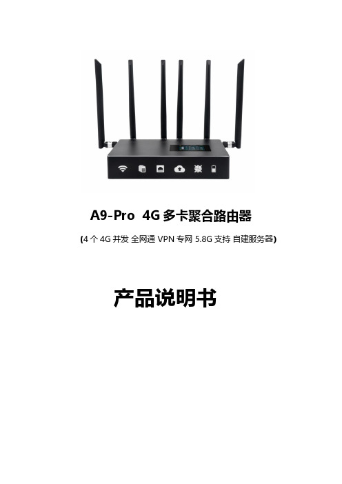
A9-Pro4G多卡聚合路由器(4个4G并发全网通VPN专网5.8G支持自建服务器)产品说明书一、产品基础信息供电电压:DC12V/3A电池容量:9000mah聚合路由器默认IP:192.168.11.1默认密码:admin说明:设备出厂已配置好我司的服务器,用户收到货,插SIM卡、开机后可直接使用,若有大型直播等用网环境,请事先充满电,提前测试好聚合路由器。
二、产品简介多卡聚合路由器是一款支持多路聚合上网的4G路由器,标配适配器DC12V/3A 供电,内置电池容量9000mah,可以使得聚合路由器续航更久,1路WAN口外网输入用于聚合,2路LAN口(LAN1和LAN2)输出到电脑或用网设备,另外还可提供2.4G和5.8G频段的无线网络,可以给更多的设备供网,以满足于用户的更多需求;多卡聚合路由器内置4个4G通信模块,支持同时混插不同运营商的SIM卡,通过云服务器聚合4条上网链路的带宽,不通过云服务器的情况下也可以单卡使用,不过只能跑单卡的流量,提升了移动环境中的上下行网络带宽,减少移动网络信号盲区,提高网络的可用性。
01三、产品接口说明1)天线1:聚合路由器的2.4G和5.8G WiFi共用这两根天线2)天线2:表示SIM卡1的4G天线3)天线3:表示SIM卡2的4G天线4)天线4:表示SIM卡3的4G天线5)天线5:表示SIM卡4的4G天线6)天线6:聚合路由器的2.4G和5.8G WiFi共用这两根天线7)显示屏7:能显示聚合路由器的工作状态等重要信息8)SIM1卡槽:插入该卡槽的4G卡,对应在显示屏上的是卡1位置,正常拨号上网,SIM1卡槽旁边的小孔处会有指示灯常闪9)SIM卡槽2:同SIM1卡槽10)SIM卡槽3:同SIM1卡槽11)SIM卡槽4:同SIM1卡槽12)ON/OFF:聚合路由器的开、关机键13)S:充电指示灯,插上DC12V/3A的适配器,电量没有充满的情况下,该指示灯长亮,充满的情况下,该指示灯灭14)电源:最新款的支持DC12V/3A供电,使用时尽量用原厂配送的适配器,若客户需另更换成自己的电源,供电电压具体咨询销售或原厂技术为准15)REST:聚合路由器重置键,用配送SIM卡的插针插进去,按住约45秒后松开,聚合路由器可恢复至出厂状态16)WAN:外网插入此口聚合路由器可以上网WAN口的网络也可以和4G网络一起聚合17)LAN1:此网口接电脑,可供电脑上网,浏览器输入IP:192.168.11.1,密码:admin,可控制路由器后台,若密码失败:建议更换浏览器继续登录或按住REST键重置路由器18)LAN2:此网口接电脑,可供电脑上网,浏览器输入IP:192.168.11.1,密码:admin,可控制路由器后台,若密码失败:建议更换浏览器继续登录或按住REST键重置路由器四、聚合路由器实操教程1、聚合路由器插入1-4张4G卡,4G卡有芯片一端朝下插入4G卡槽,如下图2、插入4根4G天线和2根天线;(备注:注意区分4G天线和WiFi天线,天线是否带针,4G天线是带针的,WiFi天线不带针)备注:WiFi天线插错会造成4G卡不识别3、按一下聚合路由器的开机键ON/OFF,该指示灯长亮,表示设备已开机,然后等待设备系统启动,完全开机全程约2-3分钟;备注:设备开机会先白屏约10秒钟,然后黑屏约43秒钟,转而出现显示屏的信息,显示屏亮了之后再等约1分钟,显示屏信息完全显示,开机全过程约2-3分钟。
12V3A美规插墙式电源适配器参数
12V3A美规插墙式电源适配器特点
• • • • • • • • • • • • • • •
产品特点: 1).小体积、重量轻、流线型、全密封、携带方便; 2).极高性价比,可靠性高; 3).内置过压、过流和短路保护; 4).输入特性:电压:100-240VAC±10%;频率:50/60Hz;电流:1.5A Max; 启动时间:3sMax;启动冲击电流:20A/240VAC Max; 5).输出特点:恒压模式;高精度,低噪音;保持时间:20mS Min; 6).环境:工作温度:0℃-40℃,5%-90%RH; 存储温度:-20℃-85℃,5%-95%RH; 7).冷却方式:自然冷却; 8).符合能效:ERP/CEC-VI标准; 9).安规标准:IEC/UL60950-1,UL62368,CSA C22.2 NO 60950-1-07, FCC PART 15, CEC-400-2014-009-CMF, 10-CFR Part 430, UL1310; 10).符合ROHS标准; 11).插脚类型:UL; 12).平均故障率:50,000小时;
12V3A美规插墙式电源适配器图片
SK05T-XXXXYYYW SK05T-XXXXYYYW SK05T-XXXXYYYW SK05T-XXXXYYYW SK05T-XXXXYYYW SK05T-XXXXYYYW
19.0V-23.9V 0.1-2.52A 24.0-30V 0.1-2.0A
12V3A美规插墙式电源适配器图片
12V3A美规插墙式电源适配器图片
12V3A美规插墙式电源适配器电性特性:
• • • • • • • • •
产品型号 输入条件 Model
输出电压
输出电流
12v电瓶充电器使用方法

12v电瓶充电器使用方法12v电瓶充电器是一种常见的充电设备,广泛应用于汽车、摩托车、船舶等各种交通工具的电瓶充电。
正确的使用方法不仅可以延长充电器的使用寿命,还可以确保电瓶充电的安全和高效。
下面将介绍12v电瓶充电器的正确使用方法。
首先,接线操作。
在使用12v电瓶充电器之前,首先要确保充电器处于关闭状态。
然后,将充电器的正极夹子连接到电瓶的正极上,负极夹子连接到电瓶的负极上。
在接线时,要确保夹子与电瓶极端的金属接触良好,避免出现接触不良的情况。
其次,选择充电模式。
12v电瓶充电器通常具有快充和慢充两种模式。
在选择充电模式时,需要根据电瓶的实际情况来确定。
如果电瓶处于较低电量状态,可以选择快充模式进行充电;如果电瓶电量较高,可以选择慢充模式进行充电,以避免过度充电损坏电瓶。
然后,开启充电器。
在接线和选择充电模式后,可以按下充电器上的开关按钮,开始进行充电。
在充电过程中,需要注意观察充电器上的指示灯,确保充电器正常工作。
如果发现异常情况,应立即停止充电并检查原因。
在充电过程中,需要定期检查电瓶的温度。
如果发现电瓶温度异常升高,应立即停止充电并排除故障,避免发生安全事故。
最后,充电完成后的处理。
当电瓶充电完成后,首先应先断开充电器的电源,然后再拔掉充电器的夹子。
在拔掉夹子时,要先拔负极夹子,再拔正极夹子,避免出现短路情况。
以上就是12v电瓶充电器的使用方法,正确的使用方法可以确保充电器的安全和高效工作,延长电瓶的使用寿命。
希望大家在使用充电器时,能够严格按照上述步骤进行操作,确保充电过程安全可靠。
钱况12伏特心电源适配器用户说明书
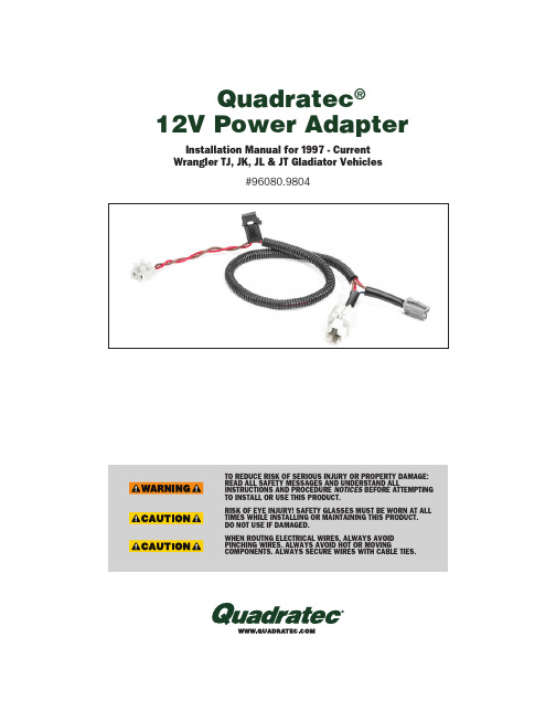
Quadratec ®12V Power AdapterTO REDUCE RISK OF SERIOUS INJURY OR PROPERTY DAMAGE:R EAD ALL SAFETY MESSAGES AND UNDERSTAND ALL INSTRUCTIONS AND PROCEDURE NOTICES BEFORE A TTEMPTING TO INSTALL OR USE THIS PRODUCT.RISK OF EYE INJURY! SAFETY GLASSES MUST BE WORN AT ALL TIMES WHILE INSTALLING OR MAINTAINING THIS PRODUCT.D O NOT USE IF DAMAGED. WHEN ROUTNG ELECTRICAL WIRES, ALWAYS AVOID PINCHING WIRES. ALWAYS AVOID HOT OR MOVINGCOMPONENTS. ALWAYS SECURE WIRES WITH CABLE TIES.Installation Manual for 1997 - Current Wrangler TJ, JK, JL & JT Gladiator Vehicles#96080.9804READ ALL SAFETY MESSAGES AND ALWAYS WEAR S AFETY GLASSES WHEN WORKING WITH TOOLS.WHEN ROUTING ELECTRICAL WIRES, ALWAYS AVOID PINCHING WIRES. ALWAYS AVOID HOT OR MOVING COMPONENTS. SECURE WIRES WITH CABLE TIES.Before You Begin Installation:Congratulations on your purchase of t he Quadratec 12 Volt Power Adapter f oryour Jeep ®Wrangler.When unpacking, check to make sure all parts are included and not damaged duet o shipping. If any part is missing or broken, please call Customer Service at 800-745-6037 as soon as possible. Thank you again for your purchase a nd let’s start the installation process.A HAZARDOUS SITUATION WHICH, IF NOT AVOIDED, COULD RESULT IN DEATH OR SERIOUS INJURY. YOU CAN BE KILLED OR SERIOUSLY HURT IF YOU DON'T FOLLOW INSTRUCTIONS.A HAZARDOUS SITUATION WHICH, IF NOT AVOIDED, COULD RESULT IN MINOR OR MODERATE INJURY. YOU CAN BE MODERATELY HURT AND ALSO MAY SUFFER PROPERTY DAMAGE IF YOU DON'T FOLLOW INSTRUCTIONS.CAREFUL ATTENTION IS REQUIRED TO THIS INSTRUCTION OR OPERATION BUT DOES GENERALLY NOT RELATE TO PERSONAL INJURY. DAMAGE TO YOUR QUADRATEC ® PRODUCT OR OTHER PROPERTY MAY RESULT IF YOU DON'T FOLLOW INSTRUCTIONS.A Few Words About Product Safety: Your 12V Power Adapter is designed to enhance the utility and enjoyment of your off road capable vehicle. Before i nstallation, please take a moment to r eview the following safety information and installationinstructions. Important safetyinformation is generally preceded by one of three signal words indicating the relative risk of injury. The signal words mean:PARTS LIST:A) Power Tap Harness QTY 1REQUIRED TOOLS:Safety GlassesForked Clip/Trim Removal Tool Ratchet7mm SocketPhillips ScrewdriverAQuadratec 12 Volt Power Adapter Harness Parts & Tools:Put on safety glasses. Using a trim clip removal tool gently remove the dash top panel. (FIG1) There are clips at the back and then it will lift off toward the rear of vehicle.Disconnect the compass module harness from the top panel. (FIG 2)FIG1FIG2For ’07-’10 JK Wrangler:For ’97-’06 TJ Wrangler:Put on safety glasses. Gain access to the back of lower dash with cigarette lighterplug and connect as shown on later model instructions (see below).Remove the two upper screws using a 7mm socket. (FIG 3) Using a trim clip removal tool gently remove the lower dash panel starting at the top. (FIG 4) There are clips at the top and then it will lift upward and out.Remove the two lower screws using a 7mm socket. (FIG 5)Gently pull the center panel away from the dash to release the clips and tiltit enough to access the 12 volt socket connection. Squeeze the white tab and disconnect it. (FIG 6)Connect the white connector on the new wiring harness to the original plug you just disconnected in FIG 6. Connect the gray connector back into the 12 volt socket. (FIG 7)FIG3FIG4FIG5 FIG7FIG612 Volt Power Adapter Harness Installation: for '07-'10 JKUnder the steering column remove the center panel by pulling it away from the dash releasing the clips. (FIG8)Remove the two screws using a 7mm socket. (FIG9)Using a trim clip removal tool gently remove the window control switch or dash pocket if switches aren’t present. (FIG 10).O n the window control switchslide the red locking tab over, squeeze the black tab and disconnect the harness. (FIG 11)Remove the center screw using a 7mm socket. (FIG 12)FIG8FIG9FIG10 FIG12FIG1112 Volt Power Adapter Harness Installation: for '11-'18 JK12 Volt Power Adapter Harness Installation: for '11-'18 JKOn top of the dash lift up the rubber tray insert and remove the screw using a 7mm socket. (FIG13).Tilt the panel away enough to access the 12v socket connection. Squeeze the black tap and disconnect it. (FIG 15)Connect the white connector to the original plug you just disconnected in FIG 15. Connect the gray connector back into the 12v socket. (FIG 16)FIG15FIG16FIG13FIG14FIG13ANext, lift the large dash top panel off carefully set aside (as highlighted in FIG 13A).Gently pull out on the climate control center to release the clips. (FIG 14)FIG17FIG1812 Volt Power Adapter Harness Installation: for '18-'Current JL & JT GladiatorTilt panel away enough to access the 12v socket connection. Squeeze the blue tab and disconnect it. (FIG 21)Connect the white connector to the original plug you just disconnected in FIG5. Connect the gray connector back into the 12v socket. (FIG 22)FIG19FIG20FIG21FIG22Put on safety glasses. Using a trim clip removal tool gently remove the center dash control center (FIG 17)Disconnect any wiring harnesses and set control panel aside. (FIG 18)Remove the center screw using a Phillips head screwdriver and set aside. (FIG 19)Gently pry out the window control panel from the top and work your way down. (FIG 20)Quadratec® Exclusive Three Year Limited WarrantyYour Quadratec® branded accessories arec overed by the following Limited Warranty provided exclusively by Quadratec, Inc., 1028 Saunders Lane, West Chester PA 19380.This Limited Warranty is the only warranty made in connection with your purchase. Quadratec neither assumes nor authorizes any vendor, retailer or other person or entity to assume for it any other obligation or liabilityin connection with this product or Limited Warranty. This Limited Warranty does not apply and is not cumulative to any accessoryor part distributed by Quadratec for whichthe Manufacturer provides a separate written warranty.What is Covered: Subject to the terms, exclusions and limitations herein and with respect only to Quadratec branded accessories first sold in the United States, Quadratec warrants to the initial retail purchaser only that your Quadratec accessory shall be free of defects in material and workmanship: for a period of three (3) years from date of retail purch ase.This Limited Warranty is not assignable and shall terminate upon sale of the vehicle upon which the Quadratec accessory is installed or other transfer third persons.All other warranties are hereby disclaimed, except to the extent prohibited by applicable law in which case any implied warranty of merchantability or fitness for a particular purpose on this product is limited to 3 year from date of initial retail sale. Quadratec reserves the rights to: (a.) require invoice or other proof your accessory is within the terms of this Limited Warranty as a condition of warranty service and, (b.) make future revisions to this product and Limited Warrantywithout prior notice or obligation to upgrade your product.What is Not Covered:Your Quadratec Limited Warranty does not cover products or parts Quadratec determines to have been damaged by or subjected to: (a.) installation damage, alteration, modification, combination with other parts, failure to maintain or improper repair or service, (b.) normal wear & tear, cosmetic damage or damage from moisture or water immersion, (c.) Acts of God, accidents, misuse, negligence, inadequate mounting or impact with vehicle(s), obstacles or other aspects of the environment, (d.) theft, vandalism or other intentional damage.Remedy Limited to Repair/Replacement: The exclusive remedy provided hereunder shall, upon Quadratec inspection and atQ uadratec’s option, be either repair or replacement of product or parts (new or refurbished) covered under this Limited Warranty. Customers requesting warranty consideration should first contact Quadratec to obtain a RGA number (610-701-3336). All labor, removal, shipping and installation costs are customer’s r esponsibility.Other Limitations - Exclusion of Damages - Your Rights Under State Law:In consideration of the purchase price paid, neither Quadratec nor any independent Quadratec d istributor/licensee are responsible for any time loss, rental costs, or for any incidental, consequential, punitive or other damages you may have or incur in connection with any part or product purchased. Your exclusive remedy hereunder for covered parts is repair/replacement as described above.This Limited Warranty gives you specific rights. You may also have other rights that vary from state to state. For example, some states do not allow limitations of how long an implied warranty lasts and /or do not allowthe exclusion or limitation of incidental or consequential damages, so the limitations and exclusions herein may not apply to you.©Quadratec, Inc. 2021. All Rights Reserved. LTR Version 6.23.21#12999.3183。
联想个人云说明书
联想个人云说明书联想个人云与市面上的NAS(网络存储器)设备在功能上基本一样,只是联想个人云搭建更简单,并且支持手机、电脑、智能电视等多平台客户端,非常适合于家庭或个人使用。
一、开箱及外观:联想个人云采用了白色硬质纸盒包装,正面印制了产品名称、外形和品牌LOGO;包装背面是产品的特色功能、参数和厂家等相关信息,整个包装看上去非常简洁。
打开包装,联想个人云被固定在底部的海绵仓位中,在盒子顶部也有海绵保护,可有效保证运输过程中的安全。
在盒子底部,是联想个人云的配件和附带的4T硬盘。
联想个人云全家福:除了主机外,还有电源适配器、硬盘、网线、说明书、螺丝及工具。
联想个人云的电源适配器型号为:E036-1C120300VC,是由迈恩普电子有限公司代加工。
从电源适配器的输出可以看到,联想个人云的供电采用的是12V 3A直流电源,在使用时,注意一定要使用原装适配器。
另外,要说的是联想个人云附带了这张4TB机械硬盘,采用的是2.5英寸西部数据蓝盘,不过要比普通的笔记本硬盘厚上许多,这或许是因为容量太大的缘故。
联想个人云的外形如立体形的跑道,主体为白色,表面采用了柱式棱角处理,加上顶部上盖和底部的底座土豪金色的点缀,让整个外观看上去非常时尚。
机身正面布置有一个指示灯,可以通过指示灯的颜值判定当前状态,相关状态可查看说明书。
▲机身正面▲机身侧面在机身的背面是联想个人云的外部接口,从上到下分别是复位孔、2×USB3.0接口、以太网口和电源接口。
在上面已经提到过,联想个人云的电源为12V输入;提供的2个USB3.0接口,可以外接U盘或移动硬盘。
▲机身背面二、安装体验:在上盖的保护膜上有“请在设备关机时插拔硬盘”和“按压LOGO 附近打开顶盖”的温馨提示。
只要轻轻按一下,就可以弹起上盖。
在上盖的内部印有设备的二维码,通过扫码就可以绑定设备。
设备连网后,也可以通过APP直接搜索绑定。
联想个人云的提供了两个硬盘槽,最大支持10TB的存储空间。
UPS12V3A电源 使用说明
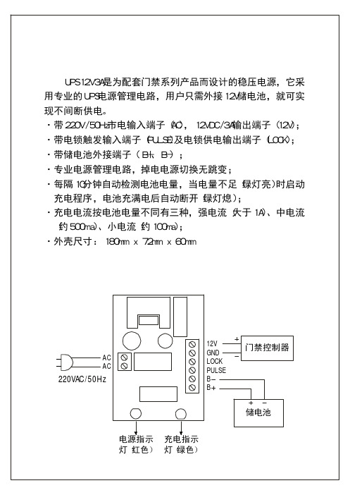
UPS12V3A是为配套门禁系列产品而设计的稳压电源,它采用专业的UPS电源管理电路,用户只需外接12V储电池,就可实现不间断供电。
·带220V/50Hz市电输入端子(AC),12VDC/3A输出端子(12V);·带电锁触发输入端子(PULSE)及电锁供电输出端子(LOCK);·带储电池外接端子(B+、B-);
·专业电源管理电路,掉电电源切换无跳变;
·每隔10分钟自动检测电池电量,当电量不足(绿灯亮)时启动充电程序,电池充满电后自动断开(绿灯熄);
·充电电流按电池电量不同有三种,强电流(大于1A)、中电流(约500ma)、小电流(约100ma);
·外壳尺寸:180mmx72mmx60mm
UPS12V3A电源使用说明
UPS12V3A电源接线示意图
电源指示灯红色
()充电指示
灯绿色
()
12V
GND
LOCK
PULSE
B
B
储电池
门禁控制器
AC
AC 220VAC/50Hz。
电源适配器规格书12V3A
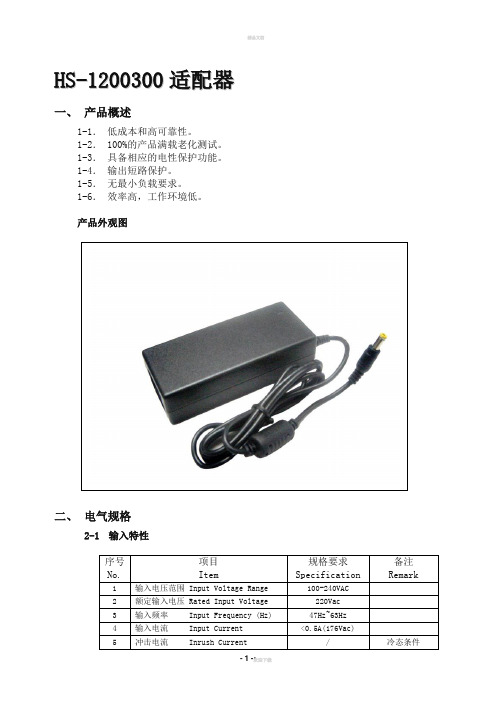
H S-1200300适配器一、产品概述1-1.低成本和高可靠性。
1-2.100%的产品满载老化测试。
1-3.具备相应的电性保护功能。
1-4.输出短路保护。
1-5.无最小负载要求。
1-6.效率高,工作环境低。
产品外观图二、电气规格2-1输入特性*: 测试时最小负载为:10%of full load.**: 测试条件为20MHz频宽,负载端并联一10uF电解电容和一0.1uF聚酯电容测试。
三、安规要求*表示耐压等级(V);允许最大漏电流(mA)。
**测试条件:试验电压为500VDC,90%RH。
3-2四、使用环境五、产品安装、使用说明1.使用时请勿超过电源标称值,以免影响产品的可靠性。
如需更改电源的输出参数,请客户在使用电源前向本司技术部门咨询,以保证使用效果和可靠性。
2.为保证使用的安全性和减小干扰,请确保接地端可靠接地(接地线大于AWG18#)。
3.本司电源主要适用于阻性为主的负载,若需应用在以容性为主或感性为主的负载时,请在订货前与本司市场部沟通,以防造成不便。
4.电源如出现故障,请勿擅自对其维修,请尽快与本司品质部联系。
六、包装、运输、储存6-1 包装包装箱上有产品名称、型号、厂家标识、厂家品质部检验合格证、制造日期等。
6-2 运输本包装适用与汽车、船、飞机、火车等运输,运输过程中应防晒、防淋,文明装卸。
6-3 储存产品未使用时应放在包装箱里,储存环境温度和相对湿度应符合该产品的要求,仓库内不应有腐蚀性气体或产品,并且无强烈的机械振动、冲击和强磁场作用。
包装箱应垫离地面至少20cm高,距离墙壁、热源、窗口式空气入口至少50cm。
如果储存时间过长(2年以上)应重新检验后才使用。
欢迎您的下载,资料仅供参考!致力为企业和个人提供合同协议,策划案计划书,学习资料等等打造全网一站式需求。
Autel MaxiSys MS906 BT 用户手册说明书

商标深圳市道通科技股份有限公司(以下称”道通公司””)已经在中国及海外若干国家进行了商标注册,Autel® , MaxiSys TM , MaxiDAS® , MaxiScan® , MaxiTPMS® , MaxiVideo TM ,MaxiRecorder TM,和MaxiCheck TM 均是道通公司的注册商标。
本产品所提及之其它产品及公司名称为其它公司分别所有的商标。
版权信息未征得道通公司的书面同意,任何公司或个人不得以任何形式(电子、机械、影印、录制或其它形式)对本说明书进行复制和备份。
免责声明和责任限制说明书中的所有信息、规格及图示均为出版截止时的最新信息。
道通公司保留对其进行更改而不另行通知的权利。
说明书中的内容已经过认真审核,但不保证其内容(包括但不限于产品规格、功能及图示)的完整性和准确性。
本公司不承担任何直接、间接、特殊、附带的损坏赔偿或任何间接经济损害(包括但不限于利润损失)。
注意:对设备进行操作与维护前,请认真阅读本说明书,尤其是安全注意事项。
服务支持销售服务热线:400-009-3838转1售后服务热线:400-009-3838转2*********************其它国家与地区的用户,请联系当地经销商寻求技术支持。
安全信息为了自身与他人的安全,同时避免对设备及车辆造成损坏,所有操作该设备的人员请务必阅读本手册中所提到的安全注意事项。
由于进行车辆维修时会运用各种程序、工具、部件及技术,同时工作人员的操作方式也各有不同,但因诊断应用程序和该设备所检测产品的种类繁多,本手册无法对每种情况进行预测并提供安全建议。
汽车维修技术人员有责任对所测试的系统进行充分的了解,并合理使用适当的维修方法和测试程序。
进行测试时,必须使用适当的操作方法,以避免对自身和工作区域内其他人员的人身安全造成威胁,同时避免对正在使用的设备或正在测试的车辆造成损坏。
12V 24V输入,12V输出3级DC-DC充电器操作手册说明书

SBC-592512V / 24V Input with 12V Output3 Stage DC-DC ChargerOperation manualKeep this manual in a safe place for quick reference at all times.This manual contains important safety and operation instructions for correct use of the battery charger.Read through the manual and pay special attention to the markings and labels of the charger,battery and equipment connected to the battery system.Pay special attention to these two types of notices used in this manual.Failure to heed this warning may cause injury to persons and damage to Equipment.Failure to observe this warning may result in damage to equipmentand improper functioning of the Charger.WARNING:●The charger is not designed for any life saving application.●The charger is designed for in-door use. Protect the charger from ingress of water.●This charger is made to charge only properly sized lead acid based batteries and Lithium Fe PO4 (LFP).●Don't recharging non-rechargeable batteries.●Charging other types of battery or under-sized lead acid batteries may cause fire or explosion.●Install the charger in accordance with all local codes.●Do not use the charger if it has been dropped or damaged.●Never attempt to charge a frozen LEAD BASED battery.Never attempt to charge LFP battery below minus five degrees C.Never attempt to charge LFP (Lithium FePO4 ) withou t built in.BMS (battery management System).●Never attempt to charge a damaged battery.●Wear protective goggles and turn your face away when connecting or disconnecting the battery.●Never place the charger on top of a battery.●Never smoke, use an open flame, or create sparks near battery or charger during normal chargingoperation as batteries may give out explosive gas.●Do not charge batteries in an enclosure (box- in) due to possible explosion of entrapped explosive gas.●If the charger does not work properly or if it has been damaged, unplug all DC connections of input andoutput.Copy RightAll rights reserved.No part of this publication may be reproduced, or transmitted in any form or by any means without the written permission from Manson Engineering Industrial Ltd.Changes in the manual.Manson Engineering Industrial Ltd. has the right to update and change the content of this manual without any prior notice and obligation.DisclaimerExclusions for documentation, Indemnity and Product application.Manson Engineering Industrial Ltd. (Manson)1) Assumes no warranty to the accuracy, suitability of technical information given in the user manuals orother documentation.2) Undertakes no responsibility or liability of losses, damages and related expenses whether specific,direct, indirect consequential or accidental which might result from the use of information given in this manual.3) Shall not be liable to anyone for any special, collateral, incidental or consequential damages inconnection with or from the use of these Manson products. The sole and exclusive liability to Manson, regardless of the form of action shall not exceed the purchase price of the Manson product.Table of contentIntroductionFeatures & ProtectionsSupplied AccessoriesInstallation ProcedureIndicators & ControlsBattery Type SelectionConnectionsCharger Control ModesAutomatic Ignition ControlManual Ignition ControlVibration Sensor ControlCancel Ignition ControlInput Voltage ControlSummary of 3 Control Modes Operation Voltages Wiring Diagrams & Connections to LED Module SpecificationsTrouble ShootingIntroductionEspecially designed for vehicles with Smart Alternator, Start-Stop, Regenerative Braking systemThe SBC-5925 is designed to address to the issues of wide swing of output voltages from the smart alternator, braking regenerative EURO 5/6 vehicles in fully charging the house battery. It is suitable for use with all old alternator system and distant house battery.The charger Booster provides fast safe charging profiles for 4 types of lead based and 2 types of Lithium FePO4 batteries.The built-in vibration sensor makes it possible to use the charger by just connecting to the starter battery terminal without touching the car’s electrical /electronic wiring thus avoiding any possible excuse of revoking the car’s warranty.The digital control design of SBC-5925 makes it automatically select & adapt to 12V or 24V input alternator/ battery system.Multistage ChargingThis is a select (battery type) and forget charger designed for fast and accurate recharge of your deep cycle house battery. The smart multistage charging enables the charger to be connected permanently to your battery banks without the worry of over charging or drying out the electrolyte.Lead acid based BatteryA 3 Stage Bulk, Absorption & Float charging profile for 4 types of lead acid based battery with maximum constant charging current at the Bulk Stage and a Constant Voltage with decreasing charging at the Absorption Stage and a reduced voltage Float Charge for maintenance when battery is full.LiFePO4 (LFP) BatteryA 2 Stage charging is specially for 2 types LiFePO4 battery and charging current stops at the end of Absorption stage.Three Charge Control Methods:Ignition Control : Charger starts charging only when ignition is on and stops charging whenIgnition is off.Vibration Sensor Control : Charger starts charging when repeated vibrations are detected and stopscharging when no vibration is detected for over 2 minutes.Input Voltage Control : This is for non-intelligent alternator with sufficient high & uniform voltage.Charging is cut off easily due to high threshold voltage to protect startingbattery.Features●Auto select for 12V or 24V car system.●Design for all alternators, conventional, smart alternators, start-stop & regenerative braking.● 3 DC Charge Control Modes to select:Vibration Sensor Control Mode.Ignition Control Mode with Automatic on when ignition is on &off when Ignition is off or Manual Control setting.Input Voltage Control.●Suitable for standard Lead Acid, AGM and Lithium Fe PO4 battery.● 3 Stage charge for 4 types of Lead Acid based batteries.●Specific 2 Stage charge for 2 types LiFePO4 battery.Protections●Self Recoverable Input Under Voltage Protection.●Self Recoverable Output Over Voltage Protection.●Self Recoverable Over Temperature Protection.●Self Recoverable Over Load Protection (C.C.) with constant current at decreased output voltage.●Self Recoverable Input Reverse Polarity Protection●Output Reverse Polarity Protection by thermal fuse.Supplied Accessories●Remote LED Indicator Module (with 2M cable) like the unit front panel.● 4 heavy duty electrical eye connectors.●One plastic wire guide.●Double side sticker tape for the Remote Indicator Module.●Two thin wires for Pin Connections●One spare 8 Pin Connection sticker labelInstallation ProcedureDo NOT install this unit in the vehicle engine bay.This is a fan cooled electronic device not for use in high temperature, corrosive and dusty environment which will drastically shortens the life and performance of the charger.This charger is designed only for internal mounting and away from direct sunlight, heat and rain. Allow at least 80mm of space at both ends for ventilation.We recommend wiring by a qualified automobile electrician to ensure local safety and on-board standard are followed1. To provide the best cooling effect, mount the unit in vertical position with the terminal end facingdownwards due to the top front exhaust design.2. First install the charger as close to the house battery as possible via a fuse.3. See Quick Start Guide to select battery type and charge functions.4. Before connect input to DC Alternator, check on type of alternator of car, for new car with smartalternator select ether Vibration Sensor Mode or Ignition Control Mode.5. Do not charge LFP battery without built in Battery Management System.6. Do not charge LFP battery below minus 5C.Indicators and ControlsFigure: 7 LED displaySET buttonThe SET button is for selection of battery & deactivate Ignition Control Mode.Long press for 5 second for battery selection and long press for 15 second to deactivate Ignition ControlMode.Charging Status LED for LEAD ACID Battery - 3 StagesCharging status LED Charging stageFast flashes Bulk chargeSlow flashes AbsorptionSolid FloatCharging Status LED for Lithium Fe PO4 Battery - stagesCharging status LED Charging stageFast flashes Bulk chargeSlow flashes AbsorptionOutput Voltage LEDThis LED shows the voltage level at the V OUT terminal.It becomes the battery voltage when there is no Load connected to the battery and no input voltage.LED status Battery Voltage LevelFast Flashes Battery Voltage lower than 12.5VSlow Flashes Battery Voltage between 12.5V and 13.6VSolid Battery Voltage higher than 13.6VBattery Type Selection1. Press and hold the only Set Button for about 5 seconds until the LED flashes.2. Quick presses will move the LED in cyclic order from Lead--> AGM--> LFP-->Type2 + Lead --> Type2 +AGM --> Type2 + LFP --> Lead-->AGM-->LFP….3. Stop at the chosen battery type and wait till LED turns to solid to lock in your selection.ConnectionsAllow 10 seconds delay time after connections are done correctly with proper input & output voltage for selected charge control.Fig.3 Terminals & 8 PIN connectors1 T+: Vibration sensor enable pin. Connect to Vout for Ignition pin to enable Vibrationsensor control. .2 Red: Connection to remote module Red wire.3 Green: Connect to remote module green wire.4 Yellow: Connect to remote module yellow wire.5 Alarm: Alarm output pin. 12V 50mA for external alarm.6 GND: Ground pin for remote module. Connect to remote control black wire.7 Ignition: Connect this pin to ignition car ignition to make the charger operate in sync withvehicle ignition control.8 Vout for Ignition: 12 Voltage signal.Short this pin to pin 7 (Ignition) to enable manual ignition control of unit to ON.Short this pin to Pin1( T+ ) to enable vibration sensor mode.*This pin is for Ignition and Vibration sensor only. Don’t connect to other devices.Charger Control ModesThere are 3 automatic charge modes plus one manual ON-OFF to switch on and off the charger to give the optimal charging current to the auxiliary battery.Automatic Ignition Control ModeAutomatic Ignition ControlIt synchronizes ON/OFF of the DC-DC charger.with the car’s ignition.This mode requires connection to the car’s Ignition Signal Terminal 15 see wiring diagram page 10 electrical circuit which gives out a positive DC Voltage from the car’s electrical wiring when the ignition is tuned on .The ignition control will set to ON once the Ignition Pin 7 is applied with 9-32V voltage. The charging operation stops when Ignition is off & engine stops running.This mode is recommended for all alternator type including Europe 6, 6+plus with start/ stop energy saving.Manual Ignition ControlYou can wire a contact switch with one end to the Ignition Pin 7 and the other to Vout for Ignition Pin 8. Shorting both pins will turn on the charger, disconnect will turn off the charger.Vibration Sensor Control ModeThe built in vibration sensor with special software control turns on the charging when trains of vibrations are detected. Installation is simple and quick and without touching the car’s electrical system for the sensor to work.Enable build-in vibration sensorThe built-in vibration sensor is enabled by connecting T+ Pin1 to Vout for Ignition Pin 8.The vibration sensor is in standby mode with output is OFF (no charging). When sensor is triggered by a series of vibrations which switch on the charger. The charging output will be switched ON for about 100 seconds continuously.Any further vibration during the 100 seconds active mode, will extend the output ON for another 100 seconds. The output will be OFF if no more vibration detected within 100 seconds of last vibration.Over ride of all Control Modes by Vibration Sensor ControlBuilt-in vibration sensor when enabled, dominates the control of output and overrides all other Control Modes including the Ignition Control. That is only vibration can make the charger start charging with output ON.To disable the Vibration Sensor: Take out the connection between the Pin1(T+) from Pin 8 (Vout for Ignition).CAUTION: DO NOT USE VIBRATION SENSOR CONTROL WHEN CAR IS ON FERRY, TRAIN OR OTHER TRANSPORT PLAFORM.REMARKOnce the Vibration Sensor Mode is disabled , the charger will return to the last selected mode.Cancel Ignition Controli) Take out connection to the Ignition pin.ii) Press and hold button for around 15 seconds until the 3 LED battery type flash at the same time.iii) Release button and charger is changed to Input Voltage Control.Input Voltage Control ModeThis mode requires increased voltage (>13.4V) of the starter battery which is only possible with short thick cable connection and a non-intelligent alternator with sufficiently high and stable charging voltage. This Control Mode is not suitable for modern cars due to wide voltage range such as Euro 5/6.Cancel the Ignition Control first in order to get into this mode.Summary of 3 Control Modes Operation voltagesCHARGE MODE12V CAR24V CARInput Voltage Output Status Input Voltage Output StatusVibration Sensor Mode< 9V> 11V Cut OFFResume to On< 18V> 22VCut OFFResume to OnIgnition Control Mode< 9V> 11V Cut OFFResume to On< 18V> 22VCut OFFResume to OnInput Voltage Control Mode< 12.8V> 13.5V Cut OFFResume to On< 25.6V> 27.0VCut OFFResume to OnThe Ignition Control and Vibration Sensor modes are suitable for Constant Voltage Alternators, Smart Alternators, Start Stop, Euro 5 and 6 engines, cars with Regenerative Braking.Wiring Diagram & connection to Remote LED ModuleIndividual fuse/ breaker is required to be close to starting battery (charger input) and close to house battery (charger output wire).Figure: Connection diagramIgnition Signal Terminal 15 (DIN 72552)SpecificationRated output power25A at 13.8VDCOptimal Efficiency≥89%Input VoltageDC Input Voltage Range9 - 16VDC (12VDC Input) / 18 - 32VDC (24VDC Input) Max. Solar Panel Open Circuit Voltage30VDCNo load input current<50mAOutput (Charge) VoltageBattery Type Absorption FloatLead14.4V13.3VLead 214.6V13.5VAGM14.2V13.1VAGM 214.7V13.6VLiFePO414.4V StopLiFePO4 214.8V StopAlarm Output12V / 50mASize(W x L x H)130x200x55 mmWeight Approx. 870gOperation Temperature-10 to +40ºC (Ambient Temperature) Operating Mode12V CAR24V CARInput Voltage Output Status InputVoltageOutput StatusVibration Sensor Mode< 9V> 11V Cut OFFResume to On< 18V> 22VCut OFFResume to OnIgnition Control Mode< 9V> 11V Cut OFFResume to On< 18V> 22VCut OFFResume to OnInput Voltage Control Mode< 12.8V> 13.5V Cut OFFResume to On< 25.6V> 27.0VCut OFFResume to OnTrouble ShootingThe Fault LED is solid on when a protection is triggered and output of the charger is off. When the cause of the fault has been clear up, Fault LED becomes off and charger returns to normal operation. Almost all the protections are by software design and self recoverable, once the cause of fault has been dealt with. There are two layers of protection for Input and Output Over-Voltage, the frst layer is by software and the second layer by hardware as a double insurance to protect the charger and the connected devices.Problem Indication Possible Causes Suggested Solution Recovery ConditionLow Voltage Disconnect (LVD) Ignition Control is not set to Auto ON Fault LED ON12V battery system:Input voltage <12.8V for20s.Check the starterbattery voltage.Use correct size cablebetween charger andstarter battery.12V battery system:Automatic recoverywhen input voltagerises above 13.4V for60s.Fault LED ON24V battery system:Input voltage <25.6V for 20s24V battery system:Automatic recoverywhen input voltagerises above 26.8V for60s.Low Voltage Disconnect (LVD) Ignition Control is set to Auto ON Fault LED ON12V battery system:Input voltage <9V for 5sCheck the starterbattery voltage.Use correct size cablebetween charger andstarter battery.12V battery system:Automatic recoverywhen input voltagerises above 11V for 5s. Fault LED ON24V battery system:Input voltage <18V for 5s24V battery system:Automatic recoverywhen input voltageraise above 22V for 5s.Output Over Voltage Protection (Output OVP)Two layers of protectionFirst layer by software Second layer by hardware Fault LED ON Software OVP:Output terminal voltage >setabsorption Voltage +0.6Vfor 2s.Disconnect any load tobattery and checkbattery voltage.If no load connected tobattery in first place.Check battery voltageif over set absorptionvoltage, disconnectbattery.Software OVP:Automatic recoverywhen the voltage onoutput terminal isreduced belowabsorption Voltage+0.3V for 3s.Fault LED ON Hardware OVP:Output terminal voltage>17.0V.FUSE will blow.Hardware OVP:Does not automaticrecoveryRequired to replace theblown FUSE.Input Over Voltage Protection (Input OVP) Two layers of protectionFirst layer by software Second layer by hardware Fault LED ONPV LED mayalso be on at thesame time.Software input OVP:Charger output will beshutdown when input DCvoltage higher than 32V.Check input batteryvoltage is not higherthan 32V.Software Input OVP:Automatic recoverywhen the voltage oninput terminal isreduced below 31.5Vfor 5s.Input Over Voltage Protection (Input OVP) by hardware.All LEDs OFFincluding theFAULT LED.Hardware Input OVP:The FUSE will blow wheninput terminal voltage higherthan 33.5V.Find out about theInput source condition& spec such asvoltage surge etc.Before replacing withthe new fuse.Hardware input OVP:Does not automaticrecoveryRequired to replace theblownFUSE.Over Temperature Protection (OTP)Fault LED ON Charger internaltemperature is too high.Check input & exhaustends have noblockage anda minimum 10mmclearance.Automatic recoverywhen chargertemperature reduce tonormal level.FAN fault Fault LED ON FAN not working Check for objectsjamming fan or Fan isout of order.Remove objects which jammingthe fan .2019/05 Rev.17673-5925-0561。
12v电瓶充电器使用方法

12v电瓶充电器使用方法
电瓶充电器是一种非常实用的设备,它可以帮助我们给车辆、摩托车、船只等设备的12v电瓶进行充电,保证它们的正常使用。
但是,很多人对于电瓶充电器的使用方法并不是很清楚,下面我将为大家介绍一下12v电瓶充电器的使用方法。
首先,当我们使用12v电瓶充电器时,需要确保电瓶充电器本身是处于关闭状态的。
在连接电瓶充电器之前,我们需要先将电瓶充电器的电源插头插入交流电源插座,然后再将电瓶充电器的充电夹分别连接到电瓶的正负极上。
在连接电瓶充电器的过程中,一定要注意先连接正极,再连接负极,以免发生短路。
接下来,我们需要根据电瓶充电器上的充电模式选择开关来设置合适的充电模式。
一般来说,电瓶充电器会有快充和慢充两种模式,我们可以根据电瓶的实际情况来选择合适的充电模式。
如果电瓶的电量很低,我们可以选择快充模式来快速充电,如果电瓶的电量较高,我们可以选择慢充模式来进行充电。
在充电过程中,我们需要留意电瓶充电器上的充电指示灯,它会显示出电瓶的充电状态。
当电瓶正在充电时,充电指示灯会亮起,当电瓶充满电时,充电指示灯会熄灭。
在充电过程中,我们需要保持充电器处于通风良好的环境中,避免长时间连续充电,以免对电瓶造成损坏。
最后,在充电完成后,我们需要先将电瓶充电器的充电夹从电瓶上拔下来,然后再将电源插头从交流电源插座上拔下来,最后再将充电器上的开关设置为关闭状态。
在使用完电瓶充电器后,我们需要将其放置在干燥通风的地方,避免受潮或者受到阳光直射。
总的来说,12v电瓶充电器的使用方法并不复杂,只要我们按照正确的步骤来操作,就能够很好地完成充电任务。
希望以上介绍对大家有所帮助,谢谢!。
12V3A(40W)开关电源电路图
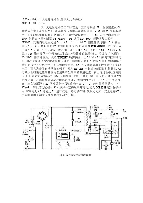
12V3A(40W)开关电源电路图(含相关元件参数)2009-11-23 12:25该开关电源电路图工作原理是: 交流电源经 BR1 全波整流及C1 滤波后产生直流高压V I ,给高频变压器的初级绕组供电. V R1 和D1 能将漏感产生的尖峰电压钳位到安全值以下,并能衰减振铃电压. V R1 采用反向击穿为200V 的瞬态电压抑制器 P6 KE200 , D1 选用1A/ 600V 超快恢复二极管 UF4005. 次级绕组电压通过D1 、C2 、L 1 、和C3 整流滤波,获得12 V 输出电压V o. V o 值是由V R2 的稳压电压V R2以及线性光耦合器中L ED 的正向压降V F 、R1 上的压降这三者之和, 即V O = V R2 + V F + V R1 . R2 和V R2 还为12V 输出提供一个假负载,用以改善轻载时的稳压性能. 反馈绕组电压经 D3 和C4 整流滤波后, 供给TOP224Y所需偏压, 由R2 和V R2 来调节控制端电流,通过改变输出占空比达到稳压目的. 共模扼流圈L 2 能减少由初级绕组接D 端的高压开关波形所产生的共模泄漏电流. C5 不仅能滤除加在控制端上的尖峰电压, 而且决定了自动重启的频率, 还与R1 、R3 一起对控制回路进行补偿. C6 可减少由初级电流的基波与谐波所产生的串模泄漏电流. 在上电过程中,直流高压 V I 建立之后需经过160ms (典型值) 的延迟时间,输出电压V o 才达到12V 的稳定值. 若需增加软启动功能以限制开启电源时的占空比, 使V o 平滑地升高, 应在稳压管V R2 两端并联一只软启动电容 C7. C7 的容量范围是4. 7~47μf . 在软启动过程中 V o 按照一定的频率升高的,能对TOP224Y起到保护作用;在断电时C7 可通过R2 进行放电. 还可以在初、次级之间加一安全电容C8 ,用来滤除加在初次级耦合电容引起的干扰.。
ASI2600 用户手册说明书

ASI2600 手册版本 1.32021年7月本手册等相关资料版权及修改权全部属于苏州振旺光电(ZWO),如有修改,不再另行通知,请于我们官方网站下载最新版本。
目录ASI2600 手册 (1)1.说明 (3)2.产品标配 (4)3.摄像头参数 (5)4. QE&读出噪声 (6)5.相机简介 (8)5.1外观 (8)5.2功耗 (9)5.3 DDR高速内存 (9)5.4 TEC制冷系统 (9)5.5后截距 (10)5.6保护窗 (10)5.7模数转换器(ADC) (11)5.8像素合并 (11)5.9 靶平面调节 (12)6.如何使用你的相机 (13)7. 机械结构图 (17)8.售后 (18)9. 质保 (18)1.说明恭喜并感谢您购买我们ASI相机!本手册是给您关于ASI相机的简介。
请花时间完整阅读。
如果您有任何问题,请随时联系我们:******************欢迎加入ZWO用户交流群,QQ: 292736278ASI2600相机是专门为天文摄影而设计的。
它不仅适合深空摄影,也可以用于行星摄影。
其卓越的性能和广泛的用途将给您留下深刻的印象!目前ASI2600有两个型号:型号黑白/彩色(TEC)半导体制冷DDR3 缓存传感器ASI2600MC Pro 彩色2级256MB SONY IMX571 ASI2600MM Pro 黑白2级256MB SONY IMX571选择何种相机?通常情况下,黑白相机传感器灵敏度更高,更能胜任高要求的拍摄工作。
但是黑白相机需要额外的配件,比如滤镜轮、滤镜等。
后期的图像处理也更复杂,所以新手我们会推荐彩色相机。
关于软件的安装说明和其它技术信息,请参考我们的官方网站:/2.产品标配ASI26003.摄像头参数传感器SONY IMX571 CMOS对角线长度28.3mm图像分辨率2600万像素6248*4176像素尺寸 3.76μm靶面尺寸23.5*15.7mm最高帧速 3.51FPS快门类型滚动快门曝光时间32μs-2000s读出噪声 1.0-3.3e量子效率(QE)峰值80%以上(彩色相机)91%(黑白相机)满阱电荷50000eADC模数转换器16bitDDR3高速缓存256MBUSB接口支持规格USB3.0/USB2.0相机接口规格M42*0.75保护窗光学玻璃AR增透膜(黑白相机)IR CUT(彩色相机)相机直径90mm相机重量0.7kg后截距17.5mm制冷方式: TEC半导体2级制冷制冷温差低于环境温度35°C制冷电源负荷12V最大3A电流支持的操作系统Windows, Linux & Mac OSX4. QE&读出噪声QE(量子效率是摄像头性能的最重要的参数。
- 1、下载文档前请自行甄别文档内容的完整性,平台不提供额外的编辑、内容补充、找答案等附加服务。
- 2、"仅部分预览"的文档,不可在线预览部分如存在完整性等问题,可反馈申请退款(可完整预览的文档不适用该条件!)。
- 3、如文档侵犯您的权益,请联系客服反馈,我们会尽快为您处理(人工客服工作时间:9:00-18:30)。
12V3A电源适配器使用说明
森树强电子
12V3A电源适配器使用说明:
1. 请在使用前仔细阅读产品规格书,参照电源标签,确认输入电网电压在固定范围;
2. 交流输入电流的计算公式:输入电流=输出功率÷输入电压÷输入功率因数÷电源效率;
3. 请不要打开电源的罩壳或分解电源以防止触电或损坏产品;
4. 为了人身安全和减少干扰,请确认安全接地线与大地可靠连接;
5. 为了提高电源的寿命,在安装时保持电源和散热设备的距离;
6. 技术人人员测试开关电源时,方法是采用带宽20MHZ的示波器,为以避免外界辐射和干扰的影响,测试时请将探头的地线夹去掉,用探头的地线环连接在电源输出的地线上,探针连接在电源的输出电压端子上。
