富莱克3200说明书
富莱克fleck软化水设备3200NT Timer 程序设置说明书
例如:
不设置[Arof] 开始再生程序
10分钟后开始再生程序
= 默认 [S- -0]
[S-10]
Timed Auxiliary Relay Output Window #1 End Time Setting
例如:
再生结束后关闭[E再生结束20分钟后关闭
92]
20]
[E-
注意: 上面所显示的所有设置为工厂默认的再生类型和格式。
逆流, 先吸盐 10 分钟 反洗, 公制,
逆流, 先吸盐
15 分钟 暂停, 公制, 逆流, 先吸盐
15 分钟 暂停, 公制, 逆流, 先吸盐
美制,
45]
[2-10] [2-10] [2-15] [2-15]
注意: 上面所显示的所有设置为工厂默认的再生类型和格式。
再生循环程序 #3
例如:
10 分钟 快 洗, 美制,
设置。 流量延迟和所有其他系统类型的设置是 [A- -7]。
再生循环程序 #1
例如:
[1-10]
10 分钟 反洗, 美制,
顺流 10 分钟 反洗, 公制,
顺流
60 分钟 吸盐/慢洗, 美制,
逆流, 先吸盐 45 分钟 吸盐/慢洗, 公制
逆流, 先吸盐 12 分钟 盐箱注水, 美制,
逆流, 先吸盐 8 分钟 盐箱注水, 公制,
Chemical Pump Auxiliary Relay Output Window #2
不设置 每200 加仑后 每200加仑后60秒钟启动
[cPof] [u200]
[t- 60]
流量计规 格
例如:
非 Fleck® 流量计 Fleck® 1" 流量计 Fleck® 1-1/4" 流量计 Fleck® 1-1/2"流量计 Fleck® 2" 流量计 Fleck® 3" 流量计
富来克全自动软化水设备操作使用手册(精)

富来克全自动软化水设备操作使用手册富来克FLECK8500/TwinFlo100e控制器调试步骤一:准备工作和注意事项a、软水设备在调试及运行前应按厂家要求安装完毕进、出水、排污管道和阀门;b、自来水、电源及排水沟准备就绪;c、打开旁通阀,让自来水冲洗管道至出水变清,然后关闭阀门;d、控制器再生程序分别为:1、快洗(Rinse2、反洗(Backwash3、吸盐与慢洗(Brine/Rinse4、盐箱注水(Brine Refill。
工作指示富莱克,全自动软化水设备,水处理耗材工作状态—灯亮当天再生—灯闪ServiceFlow 水量指示—灯闪编程模式指示灯 Program P。
M。
下午指示灯正向Up键再生Extra Cycle键反向Down键Step 1-Rinse Step 3-Brine/ RinseStep 2-Backwash Step 4-Brine Refill二:富来克软水设备调试工作富莱克,全自动软化水设备,水处理耗材1.控制器到工作位置,让水流进树脂罐,当水流停止时,打开阀门以放尽罐中空气,然后关闭阀门;2. 插上电源,观[察是否工作;3. 控制器时间设定,按动Up或Down键可调整时间,连续按住可连续调整;4. 控制器简单编程(控制器时间非12:01PMi. 同时按住Up或Down键,5秒后控制器进入编程模式,此时编程指示灯亮,每按一次Extra Cycle键,控制器程序进入下一步程序;ii. 产水量设定按动Up或Down键可以设定软水器再生前的产水量;iii. A Off:流量型专用参数,不得更改。
iv. 退出编程按动Extra Cycle键,控制器退出编程模式。
5. 控制器全面编程富莱克,全自动软化水设备,水处理耗材按动Up或Down键,将时间设定为12:01PM(必须设定为该时间,才可以进行全部程序内容的调试;然后通过按动Up、Down、Extra Cycle键即可进行对控制器全部程序内容的编程,程序内容及步骤见附表《控制器全面编程及相关代号的意义列表。
富莱克fleck软化水设备3200nxt(CN)说明书

范围:20-2,000加仑/分钟(美制) 2.0-200.0立方米(英制)
7
网络/通讯线路及联接
用CAT3或CAT5的网线。 1. 在写入程序之前先联接网线。 2. 两块面板之间最长的网线为100英尺。 3. 从一个通讯端口到另一通讯端口依次联接起每一个阀门,控制器上的两 个通讯端口等同,没有先后顺序。
锁再地
定生线 1 2
3200NXT电路板
注意:使用的网线总数会比阀门总数少一个。
3200NXT
操作手册
更多资料下载 中科软水
目录 更多资料下载 中科软水
工作记录单...........................3
控制面板运行..........................4
显示屏说明...........................6
案例: 交换容量安全系数,00%(默认值)
案例: 进水硬度,15格令/加仑(默认值) 范围:1-199格令/加仑(GPG) 2-199度Degrees)
10
注意:如果分配器模式被 选择。再生步骤不会显示。
注意:此选项只在辅助继 电器功能打开时显示。继 电器功能只在加药泵功能 关闭和6或7系统时显示。
案例: 单元交换量-格令(默认值)
选项:格令—美制(Grains)(默认值) 度—公制(Degrees)
范围:9,000-9,900,000格令—美制 90.0-190,000度—公制
注意:选择不同版本时,格令与度会相互变更
注意:本显示只出现在6
或7系统的主控制器,和 其它系统的所有控制器。
范围:0-50%
再生时或备用时启动电磁阀p6输出最大24vac5060hz025a开关火线零线t124v变压器vdm阀驱动马达sw1阀回位开关sw2阀步骤开关sw3吸盐凸轮开关hcam回位凸轮scam步进凸轮bvcam吸盐凸轮fm流量计选件m1马达或泵选件s1电磁阀可选互锁开关常开可选远控信号启动开关常开无开关火线只用于3200nxt和3214nxt触点闭合时阻止再生输入侧最大32vdc只用于3200nxt和xt如启用了此功能触点闭合时开始再生输入侧最大32vdc选装
3200系列温控器说明书
目录阅读指南…………………………1 电气连接……………… 4、5、6、7概述………………………………1 基本操作……………………… 7、8产品功能简介........................2 使用注意事项 (8)主要性能指标........................2 温度TX设定 (8)外形尺寸..............................2 异常现象处理 (9)机械安装..............................3 附件:DL420使用简介 (10)阅读指南本说明书针对不同的使用对象以3207为例对BWDK-3200系列温控器的性能指标、安装使用以及所能实现的功能进行描述,使用前请您详细阅读说明书。
●设计部门的工作人员请重点阅读主要性能指标、外型尺寸及机械安装。
●安装人员请重点参阅外形尺寸、机械安装、电气连接及使用注意事项。
●使用维护人员请重点参阅基本操作、使用注意事项及异常现象处理。
BWDK-3200系列干式变压器温度控制器是专为干式变压器进行热保护而研制生产的高新技术产品。
该温控器利用埋设在变压器三相绕组测温孔中的三支铂热电阻来测量变压器绕组的温度并进行数字显示,使您可随时了解变压器运行的温度参数,它还可以根据设定温度点自动启停风机对绕组进行风冷。
另外,该产品还设有变压器超温报警、超高温跳闸以及传感器故障报警等功能,能有效地提高干式变压器运行的安全性、可靠性以及使用寿命。
12产品功能简介主要性能指标正常工作环境温度:-10~+55℃ 控制误差:<±1℃相对湿度:5%~95% 显示方式:1位相位显示,3位半温度值显示 工作电源:AC220V ±10%,0.5A ,50Hz 外形尺寸(体积):263mm ×196mm ×85mm 测温范围:0~199.9℃ 最大功耗:10W测温精度:±0.5% 总重量:2.4kg外形尺寸前视图侧视图后视图3机械安装安装方式一:变压器本体安装安装方式二:变压器外壳安装图a 建议用安装支架结构图图b 安装后示意图图a 建议变压器外壳开孔尺寸图图b 安装示意图图c 安装后的位置图A.温控器铂电阻传感器的连接CA型铂电阻传感器电气连接图CB型铂电阻传感器电气连接图:B相B相45B .传感器的安装:安装步骤:1234传感器安装示意图C. 温控器端子排定义及接线1、3205端子排端子定义14 13 12 11 10 9 8注:1.1、2、3、4号端子空闲不用。
富莱克FLECK3200NT说明书
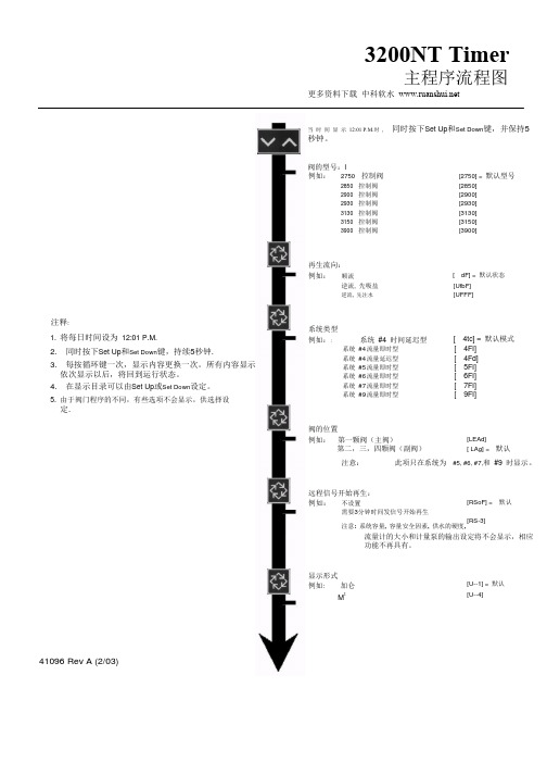
富莱克FLECK3200NT说明书富莱克 FLECK3200NT 说明书3200NT Timer主程序流程图注释:1. 将每日时间设为 12:01 P.M.2. 同时按下 Set Up 和 Set Down 键,持续 5 秒钟 .3. 每按循环键一次,显示内容更换一次。
所有内容显示依次显示以后,将回到运行状态。
4. 在显示目录可以由 Set Up 或 Set Down 设定。
5. 由于阀门程序的不同,有些选项不会显示,供选择设定 .当时间显示 12:01 P.M. 时, 同时按下 Set Up 和 Set Down 键,并保持 5 秒钟阀的型号: l例如: 2750 控制阀 [2750] = 默认型号2850 控制阀[2850]2900 控制阀[2900]2930 控制阀[2930]3130 控制阀[3130]3150 控制阀[3150]3900 控制阀 [3900]再生流向:例如:顺流 [ dF] = 默认状态逆流 , 先吸盐 [UfbF] 逆流 , 先注水[UFFF] 系统类型例如:: 系统 #4 时间延迟型 [ 4tc] = 默认模式系统 #4 流量即时型 [ 4FI]系统 #4 流量延迟型 [ 4Fd]系统 #5 流量即时型 [ 5FI]系统 #6 流量即时型 [ 6FI]系统 #7 流量即时型 [ 7FI]系统 #9 流量即时型 [ 9FI]阀的位置例如:第一颗阀(主阀) [LEAd]第二,三,四颗阀(副阀) [ LAg] = 默认注意:此项只在系统为 #5, #6, #7, 和 #9 时显示。
[RSoF] = 默认 [RS-3]远程信号开始再生:例如:不设置需要 3 分钟时间发信号开始再生注意: 系统容量, 容量安全因素, 供水的硬度, 流量计的大小和计量泵的输出设定将不会显示,相应功能不再具有。
.[U--1] = 默认 [U--4]显示形式例如 : 加仑M341096 Rev A (2/03)3200NT Timer。
logix 3200(IOM)(chinese)

1 安全相关术语
安全术语危险、警告、小心和注意在本说明书中被 用来强调特定危险和/或提供更多的非显而易见的 信息。
β 危险:表示若不采取适当的防范措施将造成死
亡、严重的人身伤害和/或重大的财产损害。
χ 警告:表示若不采取适当的防范措施将可能造
成死亡、严重的人身伤害或重大的财产损害。
α 小心:表示若不采取适当的防范措施将可能造
警告:在对本产品或任何过程控制产品进行操作时 务必遵守标准的行业安全规范。具体来说,应保证 必须使用个人防护用品和升降装置。
3 拆除包装与储藏
3.1 拆除包装
1. 在拆除 Logix 3200MD 定位器的包装时,请对照 产品装箱单检查所交付的材料是否正确。每只 运输用集装箱内都附有系统和配件清单。
使用说明书用说明书用说明书用说明书数字式定位器数字式定位器数字式定位器数字式定位器3200md安装安装安装安装操作操作操作操作维护维护维护维护实践中积累经验实践中积累经验实践中积累经验实践中积累经验使用说明书数字式定位器3200mdlgenim0059011008目录目录目录目录31拆除包装32储藏33安装前的检查logix3200md定位器简介41规格42定位器操作43详细的定位器操作顺序51安装到valtekmarkone直通控制阀上52安装到标准型valtek旋转阀上53可选的valtek旋转安装程序1154将定位器用管连接至执行器上11布线与接地指南1261420毫安指令输入布线1362接地螺钉1363顺从电压1364电缆要求1365本质安全栅14启动1471logix3200md本地界面操作1472初始dip开关设定操作1473dip开关设定的配置操作1574快速校准操作模式下校准dip开关的设置1675快速校准quickcal操作1676阀门位置的本地控制1777恢复出厂设置1778指令重置1779版本号检查17710logix3200md指示状态17711valvesight配置诊断软件和hart375手持通信维护与维修2181驱动器模块总成2182调节器2383检查或设定内部调节器压力2484柱形阀2585柱形阀盖2586阀杆位置传感器2687主板pcb组件2788压力传感器板2789用户接口板28可选硬件2991通风口部设计2992hart调制调解器3093420毫安模拟量输出板3010零部件列表3211logix3200md备件箱3412logix3200md安装套件35121valtek安装套件35122logixoem
全 自 动 软 水 器富莱克FLECK产品使用手册

全自动软水器富莱克FLECK产品使用手册MODEL FLECK2510、2750、2850 、2900、3150、3900 CONTROL VALVE产品概述FLECK全自动控制器以闻名于世的 FLECK公司软化水技术为基础,它是将软水器的运行及再生的每一个步骤实现全自动控制,并采用时间流量或感应器等方式来启动再生。
由于FLECK系列全自动软水设备控制系统技术成熟、操作简便、富来控制器采用了无铅黄铜阀体完全符合食品卫生要求,配以聚四氟乙烯(Teflon)涂层,活塞减小了阻力,延长了使用寿命,运行可靠。
FLECK系列全自动软水器可用于工业锅炉、热交换器、宾馆饭店、食品工业、戏衣印染、医疗卫生等行业,该产品具有自动化程度高、交换容量大、结构紧凑、能耗低、省人工、无需日常保养等特点。
系统技术参数进口压力:0.2 Mpa-0.6 Mpa工作温度:2 ℃—50℃出水硬度:≤0.03mmol/L使用电源:220v /50Hz AC布置形式:单罐或双罐并联再生方式:顺流再生操作程序:自动程序控制使用树脂:001×7强酸性阳离子交换树脂海扬公司将为用户提供完善的技术服务及售后服务。
MODEL2150、 2750、2850、2900、3150、3900机械式流量控制再生型流量的设定流量控制盘* 24 HOUR GEAR:在标准的即时再生系统中,没有24 HOUR GEAR(时间盘)按树脂罐内装填树脂的交换能力算出周期制水量,减去必要的储备量后的值就是所设定的流量。
向外提出流量盘并转动,使设定的流量数对准流量盘上的白色圆点,然后松开流量盘,注意让齿轮啮合好。
注意:最初安装流量计后应进行检查:1、转动手动再生阀,走一遍程序。
2、顺时针转动程序轮或顺时针转动中心轮,使设定的流量数对准小白点。
3、可随时改变设定的流量。
时间的设定(*仅指带有延时功能的系统)压下红色按扭,松开与24小时时间盘的啮合。
转动时间盘,使当天的真实时间对准写有“time of day”的箭头。
Philips 3200 系列智能瘦屏 LED 电视产品说明书

Philips 3200 seriesSlim Smart LED TV with Digital Crystal Clear107cm (42")Full HD 1080p DVB-T/C/S/S242PFL3218KDiscover a step beyond viewingWith Smart Slim LED TVEasily connect to a world of online content with the Philips 3218 series Smart LED TV with Wi-Fi. Enjoy extremely clear, vivid pictures from any source thanks to Digital Crystal Clear. Feel connected to entertainment.A world of online content at your fingertips •Skype™ for easy voice and video calls on your TV •USB adapter to enjoy Smart TV wirelessly •Smart TV—a world of online entertainment•Simply share photos, music and movies through DLNA Control how you share and record on the big screen •MyRemote app—control your TV with your phone or tablet Experience the next dimension in entertainment•Full HD LED TV—brilliant LED images with incredible contrast •100Hz Perfect Motion Rate (PMR) for clear motion sharpness •Digital Crystal Clear to enhance picture quality •Two USB slots for generous multimedia access•Two HDMI inputs and Easylink for integrated connectivity •Feel the power of 20W RMS and Incredible Surround •DivX HD Certified ® lets you play DivX videos at homeHighlightsSkype™ TV video calls*Add a new dimension to your calls and share experiences with the people that matter to you, wherever they are. With Skype™ on your TV, make voice and video calls from your living room. Just plug the optional Philips TV camera (PTA317) into your TV and enjoy excellent video and sound quality from the comfort of your couch.Wireless LAN adapter includedWe’ve included a USB adapter so you can connect to your home network with ease, allowing you to access a world of content or share wirelessly at home.Smart TV online appsExplore the boundaries that lie beyond traditional TV. Rent and stream movies, videos, games and more, directly onto your TV from online video stores. Watch catch-up TV from your favorite channels and enjoy a rich selection of online apps with Smart TV. Connect to family and friends with Skype™ or social networking. Or... just browse the Internet!SimplyShare TVShare photos, music, videos and movies through DLNA using your smartphone, tablet or computer and enjoy them on the big screen. Sharing made simple.MyRemote*Control your TV and record on the go without a remote control using one easy app. Transform your tablet or smart phone into a universal remote with all the options of your original remote plus extra features like text entry. The SimplyShare function beams content onto your TV. Stay up to date by recording your favorite programs on-the-go using MyRemote recording. Simply flip through the content on the TV Program Guide to choose which shows to record and view later.A Smart TV deserves a truly smart app.Full HD LED TVPicture quality matters. Regular HDTVs deliverquality, but you expect the best. Imaginebreathtakingly crisp detail paired with highbrightness, incredible contrast, sharp motiondefinition, realistic colors and a true to lifepicture—as well as low power consumption.Well, look no further. Full HD LED deliversmore detail than standard HDTVs. And moredetail in the image means a more intenseviewing experience for you.100Hz PMRFor picture movement that looks precise,smooth and natural, Philips created PMR—ourstandard for measuring moving imagesharpness. Perfect Motion Rate is thecombined result of our unique videoprocessing, number of frames per second andrefresh rate of each frame, perfection indimming capabilities, and backlightingtechnology. A higher PMR number contributesto higher contrast and better motionclarity—which means a superior image for you.Digital Crystal ClearEnjoy extremely clear pictures from anysource. This package of picture innovationsdigitally adjusts and optimizes picture quality tooptimal contrast, color and sharpness levels.Two USB (photos, music, video)With Two USB Slots you can keep a hard discconnected for USB recording and Pause TV soyou’ll always have control of your personalprogramming. The convenient extra USB portmeans connecting a Skype™ camera oraccessing any jpeg photos, mp3 music or videofiles stored on your USB-storage devices willnever interfere with your recording.Two HDMI inputs with EasylinkAvoid cable clutter with a single cable to carryboth picture and audio signals from yourdevices to your TV. HDMI uses uncompressedsignals, ensuring the highest quality fromsource to screen. Together with PhilipsEasylink, you’ll need only one remote controlto perform most operations on your TV, DVD,Blu-ray, set top box or home theatre system.20W RMS Incredible SurroundCreate a lifelike sound stage. Powerfulamplifiers and Incredible Surround let youexperience total surround sound with greaterdepth and width of sound to complement yourrich viewing experience.DivX HD Certified TVEnjoy DivX encoded videos in the comfort ofyour living room. The DivX media format is anMPEG4-based video compression technologythat enables you to save large files like movies,trailers and music videos on USB storagedevices.Smart TVSmart TV-a world of online apps, videosto rent and catch-upExplore the boundaries that lie beyondtraditional TV. Rent and stream movies,videos, games and more, directly ontoyour TV from online video stores. Watchcatch-up TV from your favorite channelsand enjoy a rich selection of online appswith Smart TV. Connect to family andfriends with Skype™ or socialnetworking. Or... just browse theInternet!Issue date 2022-07-14 Version: 3.0.212 NC: 8670 001 07229 EAN: 87 12581 69885 0© 2022 Koninklijke Philips N.V.All Rights reserved.Specifications are subject to change without notice. Trademarks are the property of Koninklijke Philips N.V. or their respective owners.SpecificationsPicture/Display•Display: LED Full HD•Diagonal screen size: 42 inch / 107 cm•Panel resolution: 1920x1080p•Aspect ratio: 16:9•Brightness: 350 cd/m²•Dynamic screen contrast: 100,000 : 1•Picture enhancement: Digital Crystal Clear, 100 Hz Perfect Motion RateSmart TV•Interactive TV: HbbTV*•SmartTV apps*: Catch-up TV, Netflix*, Online apps, Online Video stores, Open Internet browser, YouTube•Social TV: Facebook, Skype, Twitter•TV programe guide*: 8 day Electronic Program GuideUser Interaction•Wireless interaction: SimplyShare, MultiRoom Client*, Wi-fi Miracast Certified*, PC In Monitor •Program: Pause TV, USB Recording*•Ease of Installation: Auto detect Philips devices, Device connection wizard, Network installation wizard, Settings assistant wizard•Ease of Use: One-stop Home button, Onscreen Usermanual•Firmware upgradeable: Firmware auto upgrade wizard, Firmware upgradeable via USB, Online firmware upgrade•Screen Format Adjustments: Autofill, Autozoom, Movie expand 16:9, Super Zoom, Unscaled, Widescreen•Signal strength indication•Teletext: 1000 page Smart Text•My Remote App*: Control, MyRemote Recording, Simply Share, TV GuideSound•Output power (RMS): 20W•Sound Enhancement: Auto Volume Leveler, Clear Sound, Incredible SurroundConnectivity•Number of HDMI connections: 2•Number of component in (YPbPr): 1•Number of scarts(RGB/CVBS):1•Number of USBs: 2•Wireless connection: Wi-Fi ready•Other connections: Antenna IEC75, Common Interface Plus (CI+), Ethernet-LAN RJ-45, Digital audio out (coaxial), Audio L/R in, Headphone out, Satellite Connector •HDMI features: Audio Return Channel•EasyLink (HDMI-CEC): Remote control pass-through, System audio control, System standby,Plug & play add to Homescreen, Auto subtitle shift(Philips), Pixel Plus link (Philips), One touch playMultimedia Applications•Video Playback Formats: Containers: AVI, MKV,H264/MPEG-4 AVC, MPEG-1, MPEG-2, MPEG-4,WMV9/VC1•Music Playback Formats: AAC, MP3, WMA (v2 upto v9.2)•Picture Playback Formats: JPEGSupported Display Resolution•Computer inputs: up to 1920x1080 @ 60Hz•Video inputs: 24, 25, 30, 50, 60 Hz, up to1920x1080pTuner/Reception/Transmission•Digital TV: DVB-T/C/S/S2•MPEG Support: MPEG2, MPEG4•Video Playback: NTSC, PAL, SECAMPower•Mains power: AC 220 - 240 V 50/60Hz•Ambient temperature: 5 °C to 35 °C•Energy Label Class: A•Eu Energy Label power: 57 W•Annual energy consumption: 83 kW·h•Standby power consumption: < 0.3 W•Power Saving Features: Auto switch-off timer, Ecomode, Picture mute (for radio)•Off mode power consumption: < 0.3Dimensions•Box dimensions(W x H x D):1065 x 680 x 150 mm•Set dimensions(W x H x D):972 x 583 x 64.7 mm•Set dimensions with stand (W x H x D):972 x 631 x 250 mm•Product weight: 10.9 kg•Product weight (+stand): 12.9 kg•Weight incl. Packaging: 15.4 kg•Wall mount compatible: 200 x 200 mmAccessories•Included accessories: Remote Control, 2 x AAABatteries, Power cord, Quick start guide, Legal andsafety brochure, Warranty Leaflet, WirelessAdaptor PTA128•Optional accessories: Philips TV camera PTA317*MyRemote app and related functionalities varies per TV model andcountry, as well as smart device model and OS. For more detail,please visit: /TV.*Compatibility depends on wifi miracast certification Android 4.2 orlater. For more details please refer to your device documentation.*For smart TV app, visit /TV to discover the servicesoffering in your country*USB recording for digital channels only, recordings may be limited bybroadcast copy protection (CI+). Country and channel restrictionsmay apply.*Philips TV camera (PTA317) is sold separately.*Parents should monitor their children during 3D viewing and ensurethey do not experience any discomfort as mentioned above.Watching 3D is not recommended for children under 6 years of ageas their visual system is not fully developed yet.*The TV supports DVB reception for 'Free to air' broadcast. SpecificDVB operators may not be supported. An up to date list can befound in the FAQ section of the Philips support website. For someoperators Conditional Access and subscripction are required.Contact your operator for more information.*Software upgrade required for HbbTV, Multiroom client and server,Netflix and myRemote app.*Energy consumption in kWh per year, based on the powerconsumption of the television operating 4 hours per day for 365days. The actual energy consumption will depend on how thetelevision is used.*EPG and actual visibility (up to 8 days) is country and operatordependent.。
时间管理富莱克时间流量型水处理操作手册

最新卓越管理方案您可自由编辑富莱克Fleck2150时间、流量型控制阀使用说明书富莱克Fleck2150机械式流量控制再生型流量的设定流量控制盘* 24 HOUR GEAR:在标准的即时再生系统中,没有24 HOUR GEAR(时间盘)按树脂罐内装填树脂的交换能力算出周期制水量,减去必要的储备量后的值就是所设定的流量。
向外提出流量盘并转动,使设定的流量数对准流量盘上的白色圆点,然后松开流量盘,注意让齿轮啮合好。
注意:最初安装流量计后应进行检查:1、转动手动再生阀,走一遍程序。
2、顺时针转动程序轮或顺时针转动中心轮,使设定的流量数对准小白点。
3、可随时改变设定的流量。
时间的设定(*仅指带有延时功能的系统)压下红色按扭,松开与24小时时间盘的啮合。
转动时间盘,使当天的真实时间对准写有“time of day”的箭头。
松开红色按钮,使之与时间盘重新啮合。
如何手动再生顺时针转动手动再生旋钮(MANUAL REGENERATION KNOB),听见“卡嗒”声,这种声音标志着再生程序开始。
手动再生旋钮旋转一周大约历时3小时,旋钮转一圈完成一个再生过程。
即时启动再生当流量盘转到你所设定的数量时,定时器开始启动再生程序。
富莱克Fleck2150、2750、2850、2900、3150、3900系统工作流程:1 工作位置硬水从入口进入控制阀,通过下部活塞槽及通道,由顶部进入罐内,然后,向下穿过树脂层,成为净化水,经下布水器返回中心管,向上至阀出水口排出。
2 反洗位置硬水从入口进入控制阀,通过下部活塞槽及活塞环岸,向下经中心管、下布水器进入罐内,再向上经树脂层、控制阀流道、顶部活塞槽,从排污口排出。
反洗的目的是为了松动树脂床,清洗吸附在表面的杂质等。
3 盐吸位置硬水从入口进入控制阀,经下部活塞槽,流过射流器喷嘴产生负压,从而从盐罐吸入盐水。
盐水向下流经树脂层,穿过下布水器,沿中心管向上,流回活塞中心孔,并从排污口排出。
Blackwire 3200系列用户指南说明书

Blackwire 3200 Series User GuideContentsOverview3Setup4Load software4Fit5Adjust the headband5Position the boom 5Adjust the boom5Use the inline controller6Make/take/end calls6Volume6Mute 6Troubleshooting7Headset7Support8Call button Flashes green Incoming callSolid green On a call Volume up button Increases the listening volumeVolume down button Decreases the listening volumeMute button Solid red Headset is mutedOverviewPower on your headset by connecting to your computer or mobile device.You can connect your headset in 2 ways:1Via USB-A/USB-C connector NOTEHeadset call control functionality may vary in mobile devices.2Via 3.5 mm connector*NOTEHeadset call control functionality is not available.* 3.5 mm connector available on Blackwire 3215/3225 only.IMPORTANT Some softphones require the installation of Plantronics Hub for Windows/Mac toenable headset call control (answer/end and mute) functionality.Download Plantronics Hub for Windows/Mac by visiting /software .Manage your headset settings on your computer with Plantronics Hub:•Call control for softphones•Update firmware•Turn features on/off•View user guideSetupLoad softwareLengthen or shorten the band until it fits comfortably. The cushions should sit comfortably overthe center of your ears.This headset can be worn on the left or right side.Rotate the boom to align with your mouth.CAUTION To avoid breaking the boom, only rotate it up and over 180°.Gently bend the boom in or out so it is approximately two finger widths from the corner of your mouth.FitAdjust the headbandPosition the boomAdjust the boomHeadset call control is a software feature and dependent on a compatible softphone. If you have not installed Plantronics Hub or do not have a compatible softphone, press the headset call button first and then make/take/end the call using the softphone application. Download Plantronics Hub for Windows or Mac at /software .Answer or end a call Tap the Call button or use your softphone.Make a call Dial using your softphone application.Redial If not on an active call, double key press the call button to redial the last call.Hold Press and hold the call button for 2 seconds to put a call on hold.Listening volume Press the Volume up (+) or Volume down (-) button.Adjust headset microphone volume (softphone)Place a test softphone call and adjust softphone volume and PC sound volume accordingly.During a call, briefly press the mute button to mute the microphone on the inline controller. Tounmute press the button again.Use the inline controllerMake/take/end callsVolumeMuteI cannot hear caller.•Listening volume is too low. Press the volume up button on theheadset. and/or ensure that the volume setting on your computeris set accurately.•The analog headset is not set as the default audio device. Use theaudio settings in your sound control panel/preferences to selectyour headset as the default audio device.Callers cannot hear me.•Headset is muted. Slide the mute button up to unmute themicrophone.•Headset microphone boom aligned incorrectly. Align the headsetboom with your mouth.•The analog headset is not set as the default Voice device. Use theaudio settings in your sound control panel/preferences to changethe input device.The sound in the headset is distorted.I can hear an echo in the headset.•Lower the listen volume on your softphone until the distortion disappears.•Adjust volume on headset.The other headset I was using to listen to music does not work any more.•The analog headset will set itself as the default audio device in Windows. Use the audio settings in your sound control panel/ preferences to change the audio device.My phone is not finding my headset during a call or while listening to music.•When on a call or listening to music, make sure that audio is routing to the desired headset by going to your settings and ensuring it is defaulted.TroubleshootingHeadsetSupportNEED MORE HELP?/support***********************************Plantronics, Inc.Plantronics B.V.345 Encinal Street Santa Cruz, CA 95060 United States Scorpius 171 2132 LR Hoofddorp Netherlands© 2018 Plantronics, Inc. Blackwire and Plantronics are trademarks of Plantronics, Inc. registered in the US and other countries. All other trademarks are the property of their respective owners.Patents: US 8,504,115; 8,983,081; 9,008,319; D666,993; D667,388; D747,293; IN 245078; 245079; 268129; TW D154413; D154414; D171922. 211088-06 (08.18)。
Philips 3200系列超薄LED电视说明书

Philips 3200 series Ultra Slim LED TV with Digital Crystal Clear108 cm (43") LED TVDTMB43PFF3282Relax and enjoy a great TV night with Digital Crystal ClearThe right TV for today and tomorrow: Philips 3200 series Slim LED TV. Experience vivid images, clear sound, and all the features you need-like handy extra USB and HDMI ports-to enjoy your TV at home.The right features presented elegantly•Slim, refined stands communicate lightnessA clear, vivid picture every time•Digital Crystal Clear for precision you’ll want to share•Full HD LED TV—brilliant LED images with incredible contrastTelevision viewing at your convenience•Two HDMI inputs and Easylink for integrated connectivity•USB for multimedia playbackIssue date 2017-10-24Version: 4.0.612 NC: 8670 001 45072EAN: 69 59033 85520 7© 2017 Koninklijke Philips N.V.All Rights reserved.Specifications are subject to change without notice.Trademarks are the property of Koninklijke Philips N.V.or their respective owners. SpecificationsUltra Slim LED TV 108 cm (43") LED TV, DTMBHighlights Digital Crystal Clear For natural looking pictures from any source, Philips created Digital Crystal Clear. Whether you’re indulging in your favorite shows, movies, the news, or are simply having a few friends over for a night in, you'll enjoy it all in optimal contrast, color and B (photos, music, video)Share the fun. Connect your USB memory-stick, digital camera, mp3 player or other multimedia device to the USB port on your TV to enjoy photos, videos and music with the easy to use onscreen content browser.Modern edge feet look When setting out to create a new TV, our teams consider every aspect: from technology to design. Our new edge feet were engineered to create space beneath your TV where a traditional stand would normally sit, offering you a more immersive viewing experience. The effect? A TV that stands confidently with a nod to the future.Full HD LED TV Picture Quality matters. Regular HDTVs deliver quality, but you expect more. Imagine crisp detail paired with high brightness, incredible contrast and realistic colors for a true to life picture.Two HDMI inputs with Easylink Avoid cable clutter with a single HDMI cable to carry both picture and audio signals from your devices to your TV. HDMI uses uncompressed signals, ensuring the highest quality from source to screen. Together with Philips Easylink, you’ll need only one remote control to perform most operations on your TV,DVD, Blu-ray, set top box or home theatre system.x2Picture/Display •Aspect ratio: 4:3/16:9•Panel resolution: 1920x1080p •Picture enhancement: Digital Crystal Clear •Display: LED Full HD •Brightness: 200 cd/m²Supported Display Resolution •Computer inputs: up to 1920x1080 @ 60Hz •Video inputs: 24, 25, 30, 50, 60 Hz, up to 1920x1080p Sound •Output power (RMS): 16W •Sound Enhancement: Auto Volume Leveller, Incredible Surround, Clear Sound Multimedia Applications •Music Playback Formats: MP3•Picture Playback Formats: BMP, JPEG, PNG •Video Playback Formats: Containers: AVI, MKV, H264/MPEG-4 AVC Tuner/Reception/Transmission •Video Playback: NTSC, PAL •Digital TV: DTMB •MPEG Support: MPEG4•TV Program guide*: 8 day Electronic Program Guide Connectivity •EasyLink (HDMI-CEC): One touch play, Remote control pass-through, System audio control, System standby •Number of HDMI connections: 2•Number of USBs: 1•Other connections: Antenna IEC75, Headphone out, CVBS+Audio L/R in Power •Ambient temperature: 5 °C to 45 °C •Mains power: 198~264/ 50Hz •Power consumption: 74 W •Standby power consumption: <=0.5W Dimensions•Box dimensions (W x H x D): 1070 x 683 x 150 mm •Product weight: 6.93 kg •Product weight (+stand): 7 kg •Set dimensions (W x H x D): 970.56 x 565.96 x 88.66 mm•Set dimensions with stand (W x H x D): 970.56 x 627.18 x 193.95 mm Accessories •Included accessories: 2 x AAA Batteries, Power cord, Remote Control, Table top stand, User Manual, Quick start guide, Legal and safety brochure。
3200系列带传输器系列说明书

High Speeds -Up to 600 fpm Fast & Simple to Use Online Configurator Industry-Best Product TransfersHeavy Duty, Low Maintenance Fabric & Modular Belt Conveyors3200 SERIES CONVEYORSSuperior V-Guided Belt TrackingSizes & Measurements• 95 - 1524 mm (3.75 - 60 in) widths • 0.9 - 30 m (3 - 99 ft) lengths Loads & Speeds• Up to 454 kg (1000 lbs)• Up to 183 mpm (600 fpm)StraightZ-Frame Curve(Modular Belt Only)Horizontal to InclineNose-OverConveyor Configurations• Flat Belt• Flat Belt Cleated • Sidewall Cleated •Rib Top BeltFlat BeltFlat Belt CleatedSidewall Cleated Rib Top BeltBELTING3200 SERIES• Precision Move• Precision Move Cleated • Precision Move with Fixtures – Provides an accurate mounting bar for pallet attachmentPlastic ClipperAn optional plastic clipper splice is available for quick removal of belts or when conveyors are installed in tight spaces.Finger SpliceAll belts are available with a standard Thermoformed finger splice. This splice makes the belt continuous and isvirtually undetectable.Metal ClipperAn optional metal clipper splice is also available for quick removal of belts or when conveyors are installed in tightspaces.SplicingIn-House Fabricaton Capability • Large Quantity of Stocked Materials • Continous V-Guiding• Water Cooled Belt Splicing • RF Cleat Welding • Hole Punching• Flat Top • Flush Grid • Fricton Inserts • Cleated •Roller TopPrecision MovePrecision Movewith FixturesFlat TopCleatedHigh Strength CurveRoller TopCurved Modular Belt Types • Basic Single Curve• Low Backpressure Roller Top Curve• Friction Insert Curve • High Strength Tab Curve• High Strength Bearing CurveModular BeltNosebar TailsFabric Belt Nosebar TailsMultiple Guiding Options • Low Side• Aluminum High Side • Wiper• Fully Adjustable • Adjustable Outboard • Stainless Steel Side • Flared GuidingCenter Drive End Drive iDrive ®Industry-Best Transfers• Nosebar Drive and Idler Tails (20 mm Dia.)• Outfeed/Infeed Powered Transfer • Infeed/Outfeed Roller TransferControls• VFD Controllers• Brushless DC Controllers • Remote Start VFD Controls• Programable Servo ControlsOPTIONS3200 SERIESStandard T-Slot FrameMounting accessories is simple without drilling or special tools.SmartSlot ® FrameSmartSlot technology in the frame functions like a T-slot without the collecting of debris.Optional Mid Slot CoverProvides cover for wiring and pneumaticlines.Weighted Take-Up ModuleEliminates catenary sag and improves safety. Standard on modular belt conveyors withcurves or nosebars.StandsMultple Stand Options• Fixed Height Support Stands • Adjustable Height Support Stands• Single Post & Pillar Support StandsFlat Belt Conveyor Drive OptionsINDUSTRY LEADING TECHNOLOGY The Benefits of a Dorner 3200 Series ConveyorLow Maintenance• Dorners Industry Best V-Guiding provides positive belt tracking, even under demanding side load applications • Modular belts and spliced standard belts allow for quick belt changing, reducing downtime • Precise rack and pinion belt tensioning • Sealed for life bearingsTime Saving • D orner’s online configurator engineers simple or complex conveyors to meet your needs in minutes • T he industry leading tool delivers a complete 3D CAD assembly model for instant validation of fit • D orner provides the industry’s fastest deliveriesFlush Side Frames• All bearings and components located inside conveyorframe for flat sided tails to fit in tight spaces3200 SERIESV-Guided Belt Tracking• Superior V-Guided belting eliminates the need fortracking adjustmentsPrecision Move Conveyors• Accurate part location of up to .25 mm (.010 in) inbelt widths to 457 mm (18 in) wideiDRIVE• The industry’s most compact internal drive for 24/7operation in conveyors as narrow as 152 mm (6 in) widePowered Transfers• Provides smooth worry free transfer of parts assmall as 76 mm (3 in) in diameter, even on curvesHigh Performance Bearing Style Curve Design• Provides the capability of complex conveyor shapeswith up to 4 corner modulesOnline ConfiguratorWarrantyPartsService© Dorner Mfg. Corp. 2019. All Rights Reserved. 851-771 Rev D EGI-1M-0919128 Jalan Permatang Damar Laut, Bayan Lepas 11960 Penang, Malaysia+604-626-2948|********************。
FLECK 3200系列电动机械计时器水处理系统用户手册说明书

FLECK 3200 SERIES ELECTROMECHANICAL TIMER OWNER’S MANUAL• Greater lathering of soap• Cleaner dishes, towels, and linens• Softer skin2 • FLECK 3200 Series Electromechanical Timer Owner’s ManualMANUAL OVERVIEWHow To Use This ManualThis owner’s manual is designed to provide the equipment owner with instructions on performing routine care and maintenance of the water softener or filter valve and control packaged with this manual.This manual does not include instructions regarding installation, setup, service, or troubleshooting of the valve, control, or other components of a water conditioning system. Please contact your local water treatment professional with questions or concerns about the operation or performance of your water conditioning system.NOTE: This will make the process easier if followed.General Warningsremove or repair individual components.unplug the AC adapter from its power source.(49°C).(38°C).FLECK 3200 Series Electromechanical Timer Owner’s Manual • 33200 ModelSetting the Time of DayTo set the time of day, push the red Time Set button and spin the 24-Hour Gear until the present time of day is above the Time of Day Arrow.Setting the Skipper WheelSet the days that regeneration is to occur by sliding tabs on the skipper wheel outward to expose trip fingers. Each tab represents one day, and the red pointer on the skipper wheel points to the finger representing tonight. Moving clockwise from the pointer, extend or retract fingers to obtain the desired regeneration schedule.Forcing a Manual RegenerationTo manually regenerate the valve, turn the manual regeneration knob clockwise until the valve motor starts to turn.4 • FLECK 3200 Series Electromechanical Timer Owner’s Manual3210 ModelSetting the Time of Day To set the time of day, push the red Time Set button and spin the 24-Hour Gear until the present time of day is above the Time of Day Arrow.Setting the Program Wheel To set the program wheel, lift gallon wheel and rotate it so that the volume of water (gallons or cubic meters) can be treated is aligned with the white dot on the program wheel. Release the dial and check for firm alignment at the setting.Forcing a Manual Regeneration To manually regenerate the valve, turn the manual regeneration knob clockwise until the valve motor starts to turn.continuedFLECK 3200 Series Electromechanical Timer Owner’s Manual • 5BYPASSING THE WATER CONDITIONING SYSTEMA bypass should be installed on all water conditioning systems. A bypass isolates the conditioner from the water system and allows unconditioned water to be used while the conditioner is undergoing service or maintenance procedures or if the conditioner is experiencing performance issues. Figures 1, 2, and 3 show the most common bypass methods.Metal Bypass ValveThis type of bypass is located directly behind the conditioner valve on top of the media tank. To bypass the conditioner system using this type of bypass, turn the handle on top of the bypass until the arrow on the handle is pointing to the word BYPASS stamped on the bypass valve body.To return the conditioner system to regular service, turn the bypass handle until the arrow on the handle is pointing to SERVICE (see Figure 2).Plastic Bypass ValveThis type of bypass is also located directly behind the conditioner valve on top of the media tank. To bypass the conditioner system using this type of bypass, turn both of the small handles on the bypass until they are in the position shown in Figure 3, perpendicular to the inflow and outflow plumbing.To return the conditioner system to regular service, turn both of the small handles on the bypass back to their original positions, parallel with the inflow and outflow plumbing.Manual BypassThis type of bypass system is plumbed into the pipes of the water system, and generally consists of three valves: one on the inflow line going into the conditioning system, one on the outflow line coming out of the conditioning system, and one on the bypass line connecting the inflow and outflow lines (See Figure 4).To bypass the conditioner system using this type of bypass (following Figure 4), open Valve 2 and close Valves 1 and 3.To return the conditioner system to regular service, open Valves 1 and 3 and close Valve 2.Figure 1 Metal Bypass Valve Figure 3 Manual Bypass6 • FLECK 3200 Series Electromechanical Timer Owner’s ManualTROUBLESHOOTINGProblemSolution Control valve fails to regenerate Check for power outage and verify unit is plugged in. Attempt to perform a manual regeneration. See “SETTING TIME OF DAY AND INITIATING A MANUAL REGENERATION”. If problem still exists, contact your local water treatment professional.Water does not feel or appear softCheck salt in brine tank and ensure salt level is above water level. If problem still exists, contact your local water treatment professional.Unit uses too much saltContact your local water treatment professional.Loss of water pressureIron in conditioned waterExcessive water in brine tankOther problems with the water softenerPower Outage Reset the Time of Day in the event of a power outage/failure. See “SETTING TIME OF DAY AND INITIATING A MANUAL REGENERATION”.CARE AND USE OF YOUR BRINE TANKEach time the softener regenerates, salty water (brine) is needed to recondition the media in the water tank. The brine is pulled from the salt tank at a controlled amount. If the salt tank does not contain enough salt, the brine is weak, the media will not fully recondition and untreated water will pass through. To ensure the highest level of performance of your water conditioning system, please observe the following:• Keep the brine tank filled with salt at all times. The salt level should always be higher than the water level in the brine tank.• Only use salt designed for water softeners. Other types of salt (rock or snow melting) may contain dirt and chemicals that will affect the quality of your water and the performance of your water softener. • Keep the brine tank covered.• Empty and clean the tank every three years.FLECK 3200 Series Electromechanical Timer Owner’s Manual • 7All Pentair trademarks and logos are owned by Pentair, Inc. or its affiliates. All other registered and unregistered trademarks and logos are the property of their respective owners. Because we are continuously improving our products and services. Pentair reserves the right to change specifications without prior notice. Pentair is an equal opportunity employer.44051 REV A JA16 © 2016 Pentair Residential Filtration, LLC All Rights Reserved.For product warranties, complete service manuals, and additional resources visit: DEALER STAMP。
3200使用说明书

(1) Function mode: Displays the currently selected display (Spectrum, Bar graph, and Counter)(see page 23)(2) Scan mode: Displays the selected scan mode.3 types of scanning may be selected. See page 14 and 26 for manual scan, pages 17& 26 for search and pages 16 & 26 for channel scan.(3) Title name: The data memory, which is, selected (page 37)(4) Marker Frequency: The frequency in which the unit is currently tuned to as indicated by the marker indicator.(5) Ref.Level: The base line reference amplitude(0 level). The Reception modes (page 50)or the selected external Attenuator value (page 46)sets this value.(6) Marker Level: The amplitude value of the signal level the unit is currently tuned to as indicated by the marker.(10) Reception Mode: The type of modulation needed for aural reception of the incoming signal.Note: a CW or a signal other than a Narrow Band FM(NBFM),wideband FM(WBFM), AM or SSB may be displayed by selecting a reception mode which has the appropriate bandwidth(see page 5).button.(11) Sweep Mode: Determines how the scan moves across the screen when the squelch is activated.(See page 26)(12) Displays the value of the squelch level (see page 51).(13) Marker: Indicates the signal level currently being scanned(14) Attenuator Value: Displays the amount of external attenuation connected to the input. Whenan external Attenuator is used, the value of the Attenuator must be added to the Reference level. This is accomplished through the ATT dB set in the systemCONTENTSQuick Main Menu set up guide (ⅰ)Quick System Menu set up guide (ⅱ)Function Key Menu guide (ⅲ)Display Description (ⅳ)Ⅰ. Introduction (4)1. General (4)2. Features (4)Ⅱ. Specifications (4)Ⅲ. Precautions (7)Ⅳ. Functional Description (9)1. Panel Description (9)Ⅴ. Basic operation (12)1. General (12)1 Prior to connecting to a power source (12)2 Input connection (12)3 Powering the unit on (12)4 Entering a Frequency value (13)5 Scanning (13)6 Positioning the Frequency marker (14)7 Power Off (14)2. Manual Scan (14)3. Ch. Memory Scan (16)4. Search Scan5. Difference Mode6. Frequency Counter7. Recorder Mode8. Power supply1 Car and AC adapter2 Battery Replacement Ⅵ. Menu Description1. The Main Menu1 Main menu display2 Function Modes3 Scan Modes4 Sweep Mode5 Edit Channel 5-1 Selecting Edit Channel 5-2 Assigning a Channel number 5-3 Entering a Channel name5-4 Insert Function5-5 Delete Function1-6 Setup Memory6-1 Setup Memory6-2 Save and Load setups 6-3 Title Names1-7 Data Memory 7-1 Data Memory Setup 7-2 Saving and Loading7-3 Title name ....................................................................................17..............................................................................19...........................................................................19.................................................................................21....................................................................................22........................................................................22........................................................................22....................................................................................23.................................................................................23...........................................................................23..............................................................................23....................................................................................26....................................................................................27 (28) (28) (30)............................................................30...........................................................................32...........................................................................32.................................................................................32..............................................................................32.....................................................................34....................................................................................35 (37) (37)........................................................................38 (38)8 SSB BFO9 Hold Mode10 Level Hold 2. The System Menu1 System Menu display2 db Unit3 Power Off4 I/O Menu5 Printer Menu6 Copy Set Mode7 External Attenuators 8 Test Set Menu9 SCRB Menu10 Battery Check 11 Keyboard Buzzer 3. Function Keys …………1 RUN2 STEP3 MODE4 SQL (Squelch Level)4. LCD Men …………u 1 LCD Contrast2 LIGHT 3 GRID 4 PRINT ........................................................................................................ 39..........................................................................................39.. (41)....................................................................................42...........................................................................42............................................................................................... 43........................................................................................... 43............................................................................................ 44........................................................................................ 44....................................................................................45...........................................................................46.................................................................................47....................................................................................47.................................................................................. 48 (48)................................................................................ 49.............................................................................................. 49................................................................................................49. (50)............................................................................ 51.......................................................................................51.................................................................................51................................................................................................52...................................................................................................52 (53)I. INTRODUCTION1. GeneralThe 3201 is the world’s first hand-held RF Field Strength Analyzer.With a wide band reception range of 100 KHz to 2060MHz, the 3201is a compact and Lightweight portable analyzer. It is the ideal tool for field RF technicians to test, install and Maintain Mobile Telecommunications Systems, Cellular and Cordless Phones, CB Radios, Paging Systems, Cable and Satellite TV systems as well as antenna site measurements and Maintenance.2. Features•100KHz to 2060MHz measurement range•Measures and demodulates Narrow Band FM(N-FM), Wide Banc FM(W-FM),AM, Single Side Band (SSB) signals.•Built-in 2GHz Frequency Counter.•PLL tuning system for precise frequency tuning.•Up to 160 channels may be scanned and displayed on the LCD•Built-in Speaker•192 X 192 pixel backlit LCD•All functions are menu selectable•Has a RS-232 and parallel interfaceII. SPECIFICATIONSReception FrequencyFrequency range Freq. Accuracy (TXO) Freq. Accuracy (display) DemodulationStep frequencyData memorySet Up memory Reception sensitivityScan spee : 100KHz to 2060MHz: ±3PPM: ±25PPM: N-FM, W-FM, AM, SSB: 5KHz to 9995KHz in multiples of 5KHz and 6.25KHz: Stores 10 displays of up to 160 Channels per display(1600) : Stores 10 setups for each scan mode: Approx.0 –6 dBµEMF.(S/N: 12dB at N-FM, 10dB at W-FM): 12.5Ch./sec.max.dInput impedanceMax.Input voltageAudio output Level MeasurementN-FM mode RangeResolutionAccuracyRepeatabilityBandwidthW-FM/AM/SSB RangeResolutionAccuracyRepeatabilityBandwidth Spurious and Noise Level internally generated : 50Ω(standard): Max. 5V RMS : 120mW into 8Ωspeaker: -70 to –20dBmV(-10 to 40dB µV)for 300 to 1800MHz -60 to –20dBmV(0 to 40dB µV)for 1 to 300MHz and 1800 to 2000MHz : ±0.5dB µV : ±3dB(at an ambient of temperature of 23℃±3℃): ±2dB : Approx. 12.5KHz(-6dB): -60 to –10dBmV(0 to 50dB µV)for 300 to 1800MHz -50 to –10dBmV(10 to 50dB µV)for 10 to 300MHz and 1800 to 2000MHz : ±0.5dB µV : ±3dB(at an ambient of temperature of 23℃±3℃): ±2dB : WFM: Approx. 180KHz(-6dB), AM/SSB:Approx.2.4KHz(-6dB): -35dBc W-FM: -45dBc for N-FM typical, below a full scale signal level frequency.FunctionsDisplay modes Sweep modesScan modesHold modesLevel hold modesSquelch function Copy function : Spectrum displayMulti Bar graph display(5, 10, 20, 40, 80, 160CH)Single Bar graph displayDifference frequency displayFrequency measurement level display: Single, Normal, Free Run, Free Single : Manual, CH.Memory and Search scan : Delay run, Delay hold and delay stop : Max. Hold, Hold, 40mS, 100mS and 200ms peak hold : Squelch level is displayed as a bar graph and a digital Readout. Thesquelch level may be adjusted to any value from the reference level to Full scale: The copy set mode allows the contents of the Channel edit, Setup andData memories to be copied to an external device. Data may also be written in to these memories from an external device.Frequency CounterFrequency range No. of digits Resolution Accuracy Sampling time Input sensitivityInput impedance Max.Input voltage Data memory : 9MHz to 2060MHz: 7 digits: 1KHz:±50 PPM ±1 count: 0.512sec.: 9MHz to 2000MHz: 150mV RMS 20MHz to 1000MHz: 100mV RMS : 50Ω: 5V RMS Max.: 10 readings may be storedMiscellaeous SpecificationsLCDBack lightRS-232C Interface Power sourceAuto Power Off : 192 X 192 pixels green, Led backlit: Back light will shut off 5 seconds after the last key depression or continuously on may be selected: 1200, 2400, 4800, 9600 BPS(8 Pin Mini Din): (6)1.5V AA type NICD batteries 11V to 16V 400mA Max.AC to DC adapter, 12VDC car adapter: Unit will shut off after 5, 10, 20 or 30 minutes of idle time,menu selectable.Physical specificationsOperating Temperature & Humidity Storage TemperatureDimensionWeight : 0℃to 40℃at 35-85% RH: 10℃to 50℃: 4”(W) x 9”(H) x 1.77”(D): Approx. 1.4Ib(including antenna)Std AccessoriesCoaxial cable, earphones, Antenna (receiver only), (6)AA NiCd batteries RS232C cable, carrying Case carrying strap, Vehicle power adapter, AC/DC adapter, operators manualOptional accessories: Parallel printer cable and PR-232C mini printerIII. PRECAUTIONSStorageDo not store this equipment in:•Direct sunshine, near heating devices or in an automobile in the summer time.•Locations with high humidity and poor ventilation.•Dusty or smoky environments.•Extremely low temperature.Handling•This product is a sophisticated electronic device, do not:Service or perform adjustments.•Do not apply great force to the keys and switches.Be sure the slide switch inside the battery cover is set to the right Position, If alkaline batteries are used set the switch to right (dry position). If NiCd batteries are being used set the switch to the left (NiCd position)Warning: If the switch is in the NiCd position when alkaline batteries are used may cause these batteries to over heat, explore or leak.AntennaDue to the broad applications of this unit, the supplied antenna is for the 800MHz cellular band. It may be necessary to use a different antenna more appropriate for your application.The receiving conditions vary with location and antenna. On some occasions, it’s not possible to receive the desired signals due to strong Interference from other electronic sources such as broadcast stations.Connecting to other devicesWhen connecting this unit to other devices (CATV cable etc) be sure that the measured system voltage is not greater than the maximum input voltage. Use attenuators to preventthe input voltage from being overloaded by higher than the rated input voltage(5V rms).If the input voltage is greater than the rated input voltage of this unit, possible damage may result.Be sure that the external DC input jack is the correct polarity.The DC jack tip must be positive in respect to ground.If the unit is not functioning correctly or “locked up”when the power is turned on perform the following procedure:•Press the power button to shut the power off•keys simultaneously. This will clear the internal memory and return the unit to normal operation.Note: An alternate method to clear a malfunctioning unit is to select ALL RESET from Test set menu located in the system menu.IV. FUNCTIONAL DESCRIPTION 1. PANEL DESCRIPTION1). Signal level input connectorConnect to the Antenna or Coax cable. Maximum input Voltage is 5 Volts.2).Frequency counter inputConnect to the signal source to be measured. Maximum input voltage is 5 Volts.3). Volume controlAudio output Volume control. To increase the volume, rotate the Volume control clockwise.4). Earphone Jack5). Attenuator ““(Pushed in) Inserts 10dB of attenuation into the Signal level input. Used in the presence of noise or very strong signals.““(Pushed Out) No attenuation6). LCD (Liquid Crystal Display)Displays the Signal levels, their characteristics (frequency, amplitude, etc) and pertinent system data.7).Press this button to turn the power on. Press again to turn the power off.LCD menu items consists of LCD Contrast control, LCD Grid select, Backlight and Print command. These items arekeys.9).key a 3rd time returns the LCD to the signal level displays.10).This key enters the menu item you have selected or the numeric values you have enteredform the keyboard.These keys select: Run, Step frequency menu, Reception modemenu, and squelch Level.These keys are located at the bottom of the LCD display. They also are used to select the itemskey will enter a negative13). This key is used for entering decimal points. If a decimal point is already entered, this key isthen used for clearing a keyboard entry.14).This key is used for incrementing and decrementing the Market frequency and for selecting items in the various menus.15).Rotary Dial Knob) but at a faster rate.The rotary dial knob allows one-handed operation.16). DC Input Jack The AC/DC adapter and cigarette lighter adapter connect to this input for applying DCPower to the unit from an external source.17). RS-232C Connector(8 pin mini DIN connector)This connector is used for interfacing to a personal computer or a printer.18). Belt ClipFor attaching the RF-3201 to your belt.19). SpeakerFor listening to the demodulated output of a RF carrier signal level.V. BASIC OPERATION1. General1 Prior connecting to a power sourceSee page 22 for inserting batteries, battery charging and connecting to a power source.2 Input connectionConnect the antenna or coax cable to the BNC input marked ANT if measuring a RF carrier signal level. If measuring a frequency connect the coax cable to the Frequency counter input.Note: Do not exceed 5V rms3 Powering the unit on[2] The welcome screen will be displayed followed by the last screen that was displayed prior toshutting the power off.[4] See the graphic below for a description of the LCD display when powered on.[5] Adjust the volume control for an appropriate sound level. If the signal level is belowthe squelch level there will be no output sound from thespeaker.key to quit.4 To enter a frequency value[1] The selected scan mode is displayed in the top center of the LCD. In the above,example manual scan was selected. The frequency entered from the keyboard in thiscase is the is the center frequency and is the frequency indicated by the market.Note: in order to enter a frequency from the keyboard scanning must be halted.Example1: To enter 100.00625MHz from the keyboard: Press the following key sequence:Example2: To enter 500KHz press the following key sequence:Note:but if the decimal point has[3] The frequency value has different functions for the Manual, Search and Cannel scan.The entered frequency in manual scan sets the Center frequency where as the entered frequency values in search scanning sets the Start and stop frequencies.In the Channel scan mode the entered frequency value is stored along with its channel name in the Channel memory (see page 28 through 30). This will be used for scanningpreviously stored scans along with their channel namesand frequency.5 Scanningicon and the scanning will start.[2] If Free Run sweep is selected from the Sweep menu scanning will be continuous andkey a second time will stop the scanning.[3] When Normal Sweep has been selected the scan will halt when the signal level value isgreater than the squelch level. Scanning will resume when the signal level value dropsbelow the squelch level.[4] When scanning is halted the marker will indicate the signal level and display theamplitude value on the LCD.6 Positioning the Frequency Marker indicatorwhen the scanning has been halted can be used to position the marker frequency indicator over asignal level in order to find it’s frequency andsignal level amplitude values.7 Power Offfinished.Note: When the unit is powered-on again, the screen prior to powering off will be displayed.2. Manual Scan Mode[1] when Manual scan mode is selected, It is necessary to enter the following information:a) The Center frequency value from the keyboard,menu.c) The Frequency Span which is set by the Step frequency. The Frequency span isdetermined by the number of channels per displayed (Selected from the function menumultiplied by the step frequency. See the 2 examples below on how the frequency spanis determined by the step frequency.Example 1: To set a frequency span of 8MHz using the Spectrum display mode a stepfrequency of 50KHz is required(160 x 0.050MHz = 8MHz).Example 2: If a 40 Bar graph display is selected and the step frequency is 100KHz theFrequency span is 40 x 0.1MHz = 4MHz.[2] To select the Manual scanning mode press the following key sequence:(Select the Scan menu) (Select Manual Scan mode)[3] The center frequency, Span, Step Frequency and reception mode are displayed in the lowerpart of the LCD.Note:The frequency span is not displayed in the 2 channel difference, Single or counter modes.[4] To enter the Center/Market frequency the unit must not be Scanning (Run icon not highlighted)(See pages 12 and 13)[5] When the scanning is stopped the Market frequency indicator may be positioned over akeys or rotating the dial knob.The position of the market may be moved by up to 160 channels.(+80 channels to –80 channels)In the 2-channel mode the market/center frequency and the difference frequency are scanned and displayed.Note:Scanning is not available in the signal channel or counter mode.[7] You can save 10 displays of up to 160 channels and their setups by storing them in the Dataand setup memory. These may be selected from the main menu.(see pages 32 through 38)[8] Example of a manual scan display3. Ch. Memory Scan[1] Names and frequencies of signal levels of interest may be entered and stored in thechannel memory prior to scanning. When scanned these signal levels will be displayedalong with their frequencies and name.Ten displays of up to 160 signal level Channels per display(1600 channels total) may beentered, edited and stored in the channel memory (See pages 28 through 30)[2] To select the Channel scan mode press the following key sequence.(Select Scan Mode) (Select Chan.Scan)[3] The LCD will display the current signal level frequency as indicated by the marker, thesignal amplitude, and the channel name displayed at the bottom of the LCD.[4] A signal level frequency may also be entered in to the channel memory from the keyboard(see page 12 for entering frequencies).The type of reception (demodulation) must also be selected(see page 48).The step frequency will be indicated but is not used for the Channel scan mode.the left most position (The RUN icon is highlighted).frequency indicator and display the amplitude, frequency and name of the signal levelsdisplayed on the LCD. The market indicator may be moved up to +80 channels to –80channels from its present position.Note:Scanning is inoperative in the Single scan and counter modes.In the Difference mode only the Market and the difference frequency is scanned and displayed.[7] A stored display in the Data memory may be scanned and displayed in the channel scanmode. The set up memory in this case is used for selecting the stored display to be scanned.[8] Example of a channel scan display:4. Search Scan[1] Search scan is the scanning between a start stop frequency, which are entered from thekeyboard.[2] To selected the scan mode enter the following key sequence:(Select the Scan menu) (Select search Scan)[3] The START, STOP, STEP frequencies and the reception mode (demodulation type) willbe displayed at the bottom of the LCD with the start frequency highlighted.[4] Enter the START FREQUENCY from the keyboard. This frequency will now be displayedas the start frequency and at the market frequency indicator (See page 12).When the START frequency is entered, STOP FREQUENCY will be highlighted.Enter the STOP frequency from the keyboard.Note ;scanning must be stopped before entering the START and STOPfrequencies.frequency indicator at the step frequency increment to different positions depending on which key is pressed or which direction the rotary dial is rotated.Marker frequency indicator will update at the step frequency increment until it reaches the STOP frequency. When the stop frequency is reached the scanning will start over at the start frequency if Free Run or Normal sweep was selected or stop if Free single or single sweep was selected.signal where the Marker frequency indicator halted will be displayed.[8] If the Scan mode is changed to Manual Scan the frequency where the marker halted(in step 7) will become the center frequency.[9] You can save 10 displays of up to 160 channels per display and their setups by storing themin the Data and setup memory in the main menu. (See pages 32 through 38)5. Difference modeScans and displays 2 signal levels in which one signal level frequency is entered from the Keyboard and the other signal level is at a difference frequency selected from the step Frequency menu. The amplitude of each is displayed as a bar graph on the right side of the Display along with their signal difference.This feature is useful for measuring the difference in amplitudes between the video carrier And audio carriers of a TV signal or measuring the variation in amplitude of a transmitted Signal at different locations[1] To select the 2 channel difference mode press the following key sequence:(Select the Function mode) (Select 2 channel Difference)[2] Enter the marker frequency to be measured from keyboard.[3] Select or enter from the keyboard the difference frequency to be measured form the step[4] The LCD will display the bar graphs of the marker frequency and difference frequency amplitudes. The difference amplitude between the two signal levels will also be displayed.6. Frequency Counter The frequency counter may be used to measure and record unknown frequencies[1] To select the frequency counter press the following key sequence (select Function) (select counter)[3] Connect the signal source output to the counter input Note : Maximum input voltage is 5Voltssignal is measured, is frequency value will be stored in the data memory starting at frequency position #1 (see page 38).If the input frequency values changes the new frequency value will be stored insuccessive positions until all 10 positions are written. Additional frequencies will then displace previously stored frequencies starting with the 1position.will be the displayed at the marker indicator [6] A frequency stored in the counter data memory may be recalled by selecting the desiredused as the center frequency when set to the manual-scanning mode.Difference Display (Pg. 19) Counter Display (Pg. 19)7. Recorder functionThe 3201 may be used to display and record (store in memory) trends and variations of a Signal level as a continuous pattern of bar graphs. This feature is convent if the amplitude Variations of a signal level under test need to be monitored over a period of time.To set the Recorder mode use the following procedure:[1](Select the Scan menu) (select Manual or search scan)[2] (Select the function menu) (Select spectrum or bar graph display)[3] Input from the keyboard the frequency to be measured. If using the Manual scan mode setthe center frequency of if using the search scan input the start frequency.[4] Set the step frequency to 0㎑. This may be accomplished as follows:key.Then press the following key sequence:The scan will start from the left side of the LCD at a rate of 80mS/CH or 12.5Ch/Sec.This is 3.2sec/Div. In the 80Bar graph display the scanspeed is 6.4Channels per second or 1.6 sec per division.[6] The displays and settings may be stored in the data and setup memories8. Power supply1. Car adapter and Ac adapter[1] Before connecting be sure the power is off[2] Connect the AC adapter to the external DC input jack (see page 9 for location)2. Battery replacement[1] Shut of the power and remove the external power adapter.[2] Remove the screws form the battery cover. Lift the battery cover and remove the 6 AAbatteries.[3] Set the slide switch according to the type of battery being installed. (To the left foralkaline or manganese batteries (dry). To the fight for NiCd batteries)[4] Insert the new batteries into the case. Observe battery polarity.[5] Replace the battery cover and reinstall the screw.[6] Check to the Battery test indicator in system menu (see page48) for the conditionof the battery installed.[7] For a quick charge it is recommend charging the batteries while the power is off.When using the car adapter recharge the batteries while the engine is operatingⅥ. Menu Description1. The Main Menu1. Main menu display☞To display the main menu Press the following keys(select the desired menu)Main Menu Display 2. Function modeThe Function mode selects the type of LCD display.☞Press the following keys to select the Function mode:(select the Function mode) (select the desired display)▶Scans 160 Channels and displays their signal levels as a spectrum. The channel at the marker indicator will have its frequency and amplitude displayed on the LCD. See figure 1 on page 25.▶Scans 160 Channels and displays their signal levels as bar graphs. The channel at the marker indicator will have its frequency and amplitude displayed on the LCD. See figure 2 on page 25.▶Scans 80 Channels and displays their signal levels as bar graphs. The channel at the marker indicator will have its amplitude and frequency displayed on the LCD. See figure 3 on page 25.▶Scans 40 Channels and displays their signal levels as bar graphs. The channel at the marker indicator will have its amplitude and frequency displayed on the LCD. See figure 4 on page 25.▶Scans 20 Channels and displays their signal levels as bar graphs. The channel at the marker indicator will have its amplitude and frequency displayed on the LCD. See figure 5 on page 25.▶Scans 10 Channels and displays their signal levels as bar graphs. The channel at the marker indicator will have its amplitude and frequency displayed on the LCD. See figure 6 on page 25.▶Scans 5 Channels and displays their signal levels as bar graphs. The channel at the marker indicator will have its amplitude and frequency displayed on the LCD. See figure 7 on page 25.▶Scans and displays 2 signal levels in which one frequency is entered from the keyboard and the other signal level is at difference frequency selected from the step frequency menu. The amplitude of each is displayed as a bar graph along with their difference amplitude. See Figure 8 on page 25.▶Displays a single frequency and its amplitude as a bar graph. See figure 9 on page 25.▶Displays a measured frequency together with its amplitude as a bar graphsee figure 10 on page 25.。
Flowserve Logix3200IQ说明书(英文)

-PHJY 1PTJUJPOFST/05& 5IJT mMUFS JT OPU SBUFE GPS VTF JO IB[BSEPVT BSFBT *U TIPVME CF MPDBUFE CFUXFFO UIF DVSSFOU TPVSDF BOE UIF CBSSJFS JO JOUSJOTJDBMMZ TBGF BQQMJDBUJPOTValtek Spring Cylinder Linear ActuatorsGENERAL INFORMATIONThe following instructions are designed to assist in installing, troubleshooting and servicing Valtek spring cylinder actuators. Product users and maintenance personnel should thoroughly review this bulletin prior to installing, operating or disassembling the actuator. Separate installation, operation and maintenance instructions cover additional features (such as hand-wheels, limit stops, fail-safe systems or limit switches).This publication does not contain information on Flowserve positioners. Refer to the appropriate instal-lation operation and maintenance instructions for installing, maintaining, troubleshooting, calibrating and operating Flowserve positioners.To avoid possible injury to personnel or dam-age to valve parts, WARNING and CAUTION notes must be strictly followed. Modifying this product, substituting non-factory or inferior parts or using maintenance procedures other than outlined could drastically affect perfor-mance, void product warranties and be hazard-ous to personnel and equipment.WARNING: Standard industry safety practices must be followed when working on this or any process control product. Specifically, personal protection and lifting devices must be used as warranted.UnpackingWhile unpacking the actuator, check packing list against materials received. Lists describing the actuator and accessories are included in each shipping container.1.Position the lifting straps and hoist to avoid damageto the tubing and mounted accessories when lifting the actuator from the shipping container.WARNING: When lifting an actuator with lifting straps through the yoke legs, be aware the center of gravity may be above the lifting point. Therefore, support must be given to prevent the actuator from rotating or causing serious injury to personnel or damage to nearby equipment.2.Contact your shipper immediately in the event ofshipping damage.3.Contact your Flowserve representative for anyproblems.InstallationPrior to installation, make sure adequate overhead clearance for the actuator is provided to allow for proper removal from the valve body and for proper mainte-nance. Refer to Table 1.NOTE: If the actuator is attached to a valve body assembly, see Installation, Operation, Maintenance In-structions 1 for overhead clearances.Table 1:Overhead Clearance for DisassemblyActuator Size Minimum Clearance25 6 inches508 inches100,200,300400,500,6001.Connect the air supply and instrument signal airlines to the two appropriately marked connections on the positioner. Since both the cylinder and positioner are suitable for 150 psi air supply, an air regulator should not be used unless the supply exceeds 150 psi.NOTE: In some cases, air supply must be limited to 100 psi rather than 150 psi; this will be indicated bya sticker found near the upper air port on the cylinder.WARNING: To avoid personal injury or equip-ment damage, do not exceed recommended supply pressure.2.Installation of an air filter on the supply line isrecommended.e a soap solution to make sure all air connectionsare leak free.MAINTENANCEAt least once every six months, check for proper opera-tion by following the preventative maintenance steps outlined below. These steps can be performed while the actuator is in service and, in some cases, without interrupting service. If an internal problem is suspected with the actuator, refer to the “Disassembly and Reas-sembly” section.1.Examine the actuator for damage caused by corro-sive fumes and process drippings.2.Clean the actuator and repaint any areas of severeoxidation.3.If possible, stroke the actuator and check forsmooth, full-stroke operation.WARNING: To avoid serious injury, keep hands, hair and clothing away from all moving parts while operating the actuator.4.Make sure positioner mounting bolts, linkage andstem clamp are securely fastened.5.Ensure all accessories, brackets and associatedbolting are securely fastened.6.If possible, remove air supply and observe actuatorfor correct fail-safe action.7.Check rubber bellows for wear.8.Spray soap solution around the cylinder retainingring, the adjusting screw and the lower actuator stem bushing to check for air leaks through the O-rings and gasket.9.Clean any dirt or foreign material from the actuatorstem.10.If an air filter is supplied, check and replacecartridge as necessary.DISASSEMBLY AND REASSEMBLY Disassembling the ActuatorRefer to Figures 1 through 5 to disassemble the cylinder actuator.1.Shut off air supply. If actuator is installed on aFlowserve valve, remove the valve per Installation Operation, Maintenance Instructions 1.WARNING: To avoid serious injury, depressur-ize the line to atmospheric pressure and drain all fluids before working on the actuator.2.Disconnect all tubing. Remove stem clamp andstem bellows from the actuator stem.3.Relieve spring compression completely by remov-ing the adjusting screw. Remove adjusting screw gasket from adjusting screw.CAUTION: Do not use a screwdriver or bar to turn the adjusting screw; instead, use a wrench on the flats of the screw.WARNING: To avoid serious personal injury, relieve the spring compression before further disassembly. The cylinder could possibly fly off the yoke when removing the cylinder retaining ring.4.Remove the cylinder retaining ring from the grooveat the base of the cylinder by using two screw-drivers. Insert one screwdriver in slot found in the ring and pry the ring from the groove. Use the other screwdriver to help work the ring out of the cylinder groove.5.Pull the cylinder off the yoke and piston; someO-ring resistance may be felt.WARNING: To avoid serious personal injury, do not use air pressure to remove the cylinder.The cylinder could possibly fly off the yoke.6.For heavy-duty spring designs using a spring cap(see Figure 4), remove the spring cap and cap O-ring from the cylinder.7.For air-to-retract configurations, remove thespring(s) and spring button for cleaning and inspec-tion (see Figures 1, 3 and 5). Remove the actuator stem locknut and slide the piston and stem spacer off the actuator stem. The spring guide should be removed when using heavy-duty spring designs.NOTE: The dual, heavy-duty spring configuration (Figure 3) has two springs, one inside the other.Remove both springs during this step.9 inchesFor air-to-extend configurations, slowly loosen and remove the actuator stem locknut. Be certain the piston follows the stem locknut up the actuator stem and does not bind on the actuator stem. Remove the actuator stem locknut, spring button, piston, spring and stem spacer.WARNING: To avoid personal injury, be certain the spring force is completely relieved before removing actuator stem locknut.8.Remove the piston O-ring, piston stem O-ring andyoke O-ring.9.Remove the actuator stem O-ring.NOTE: The upper and lower stem bushings are pressed into the yoke. Removal of the bushings to replace the actuator stem O-ring is unnecessary.e appropriately sized press to push worn ordamaged bushings out of yoke.Reassembling the ActuatorTo reassemble the cylinder actuator, refer to Figures 1 through 5:1.All O-rings should be replaced. New O-rings shouldbe lubricated with a silicone lubricant (Dow Corning 55M or equivalent). Silicone O-rings must be lubri-cated with Magnalube-G lubricant or equivalent. Do not use silicone lubricant on silicone O-rings.2.Thoroughly clean all internal parts before beginningassembly. Lubricate cylinder wall with silicone lubricant.3.Lubricate the outside of the replacement bushingsif the stem bushings have been removed. Press a new lower stem bushing into the actuator stem borein the yoke until it bottoms out. Press the upper stem bushing into the bore until it is flush with the top of the yoke (refer to Figures 1 or 2).4.Replace the actuator stem O-ring and yoke O-ring.5.Reassemble the piston, piston stem O-ring andstem spacer on the actuator stem according to the proper air-action (refer to either Figure 1 or 2).Replace the piston O-ring. Air-to-extend configura-tions require the spring button to be stored under actuator stem locknut. Tighten the locknut firmly.NOTE: When reassembling heavy-duty, spring-design actuators, the spring guide must be first inserted under the actuator stem locknut (see Figures 3 and 4).6.For air-to-extend configurations, place the springunder the piston and insert the actuator stem through the yoke, being careful not to pinch the actuator stem O-ring or gall the stem and stem bushings. For air-to-retract configurations, insert the actuator stem through the yoke and place the spring(s) and spring button above the piston.7.Replace the cap O-ring and install the spring cap inthe cylinder when using heavy-duty spring designs using spring caps (see Figure 4).8.Install the cylinder, making sure the yoke is pusheddeeply enough into the cylinder to allow the cylinder retaining ring to be installed. Care should be taken not to scar or cut the piston and yoke O-rings.9.Reinsert the cylinder retaining ring by until it snapsin place. Use a hammer and drift punch to lightly tap the retaining ring in the groove.WARNING: To avoid personal injury, the cylin-der retaining ring must be solidly in place. The cylinder could possibly fly off when pressur-ized. Be careful not to pinch or cut fingers on the square edges of the retaining ring during installation.10.Reinstall the adjusting screw using a new adjustingscrew gasket.NOTE: Be certain the hole in the spring button is directly centered under the adjusting screw hole in the cylinder on air-to-retract configurations.11.Tighten the adjusting screw enough to provide anair seal with the gasket. Do not overtighten.12.Reinstall the stem bellows and stem clamp.NOTE: To ensure maximum clamping strength when installing the stem clamp, make sure the stem clamp bolting is perpendicular to one of the slots machined into the actuator stem.13.Apply air over the piston. Tighten the stem clampbolting with the stem clamp adjusted to point at the closed position of the stroke indicator plate.NOTE: If the actuator is installed on a Flowserve valve, refer to Installation, Operaton, Mainte-nance Instructions 1 for correct plug stem thread engagement.14.Reconnect tubing, supply and signal lines.Reversing the Air-actionTo change the air action from air-to-retract to air-to extend, or vice versa, refer to Figures 1, 2 or 5: NOTE: Heavy-duty spring actuators are not reversible.1.Disassemble the actuator according to the “Disas-sembling the Actuator” section.2.For air-to-retract action, reassemble the actuatorwith stem spacer and spring button over the piston.3.For air-to-extend action, reassemble with springand stem spacer below the piston and with the spring button stored above the piston.4.Reassemble the actuator according to the “Reas-sembling the Actuator” section.5.The positioner must also be reversed. See theappropriate positioner maintenance instructions.TroubleshootingProblem Probable Cause Corrective ActionHigh air consumption or 1.Leaks in the air supply or instru- 1.Tighten connections and replace any leakage ment signal system leaking lines2.Malfunctioning positioner 2.Refer to appropriate positionermaintenance bulletin3.Leaks through O-rings or adjusting 3.Replace O-rings or gasketscrew gasketActuator does not move to 1.Air pressure in cylinder not venting 1.Refer to appropriate positionerfail position upon loss because of faulty positioner maintenance bulletinof air supply pressure 2.Spring failure 2.Replace spring3.Internal valve problem 3.Refer to valve’s maintenance bulletin Jerky or sticking 1.Insufficient air supply pressure 1.Check air supply and any filters or stem travel regulators; check for leaking O-rings2.Unlubricated cylinder wall 2.Lubricate cylinder wall with siliconelubricant3.Worn or damaged stem bushings 3.Check actuator stem for damage;replace actuator stem, O-ring, andstem bushings, if necessary4.Improperly assembled spring 4.Disassemble actuator and checkcylinder and piston for damage;reassemble actuator correctly5.Internal valve problem 5.Refer to valve’s maintenanceinstructionsFlowserve Corporation has established industry leadership in the design and manufacture of its products. When properly selected, this Flowserve product is designed to perform its intended function safely during its useful life. However, the purchaser or user of Flowserve products should be aware that Flowserve products might be used in numerous applications under a wide variety of industrial service conditions. Although Flowserve can (and often does) provide general guidelines, it cannot provide specific data and warnings for all possible applications. The purchaser/user must therefore assume the ultimate responsibility for the proper sizing and selection, installa-tion, operation and maintenance of Flowserve products. The purchaser/user should read and understand the Installation Operation Maintenance (IOM) instructions included with the product, and train its employees and contractors in the safe use of Flowserve products in connection with the specific application.While the information and specifications presented in this literature are believed to be accurate, they are supplied for informative purposes only and should not be considered certified or as a guarantee of satisfactory results by reliance thereon. Nothing contained herein is to be construed as a warranty or guarantee, express or implied, regarding any matter with respect to this product. Because Flowserve is continually improving and upgrading its product design, the specifications, dimensions and information contained herein are subject to change without notice. Should any question arise concerning these provisions, the purchaser/user should contact Flowserve Corporation at any of its worldwide operations or offices.。
Philips 3200 系列 LCD 电视мини指南说明书

Philips 3200 seriesLCD TV with LEDbacklight with Pixel Plus50"Full HD (1920x1080p)50PFL3240Enjoy a great TV nightPhilips brings a LCD TV of excellent quality at an affordable priceGood picture quality•Full HD LCD display, 1920x1080p resolution•PMR 100•Pixel PlusGreat sound quality•Incredible Surround for enhanced audio enjoyment•10W per channel stereo with Dynamic Bass EnhancementEasy connectivity•USB photo, music and video•2 HDMI inputs for full digital HD connection in one cableIssue date 2019-06-22Version: 4.0.112 NC: 8670 001 09331EAN: 69 59033 85050 9© 2019 Koninklijke Philips N.V.All Rights reserved.Specifications are subject to change without notice. Trademarks are the property of Koninklijke Philips N.V. or their respective Specifications LCD TV with LED backlight 50" Full HD (1920x1080p)HighlightsIncredible Surround Incredible Surround is an audio technology from Philips that dramatically magnifies the sound field to immerse you in the audio. Using state-of-the-art electronic phase shifting, Incredible Surround mixes sounds from left and right in such a way that it expands the virtual distance between the two speakers. This wider spread greatly enhances the stereo effect and creates a more natural sound dimension. Incredible Surround allows you to experience total surround with greater depth and width of sound, without the use of additional B photo, music and video USB photo, music and video 2x10 W RMS audio power In audio, the more the watts, the louder the sound. 2x refers to stereo speakers,with 10 watts per speaker. 10 watt RMS amplification is consideredvery good for a TV set Picture/Display •Aspect ratio: 16:9 widescreen •Diagonal screen size: 50 inch / 127 cm •Display screen type: Active Matrix LCD, Full-HD •Panel resolution: 1920x1080p •Picture enhancement: 3/2 - 2/2 motion pull down, 3D Combfilter, Dynamic contrast enhancement, Sharpness Adjustment, Color Enhancement, Pixel Plus HDSupported Display Resolution •Computer formats Resolution Refresh rate 640 x 480 60Hz 800 x 600 60Hz 1024 x 768 60Hz 1360 x 768 60Hz 1920 x 1080 60Hz •Video formats Resolution Refresh rate 480i 60Hz 480p 60Hz 576i 50Hz 576p 50Hz 720p 50, 60Hz 1080i 50, 60Hz 1080p 50, 60HzSound •Output power (RMS): 2x10 W •Sound Enhancement: Auto Volume Leveller, Incredible Surround •Sound System: Mono, StereoConvenience •Child Protection: Child Lock+Parental Control •Clock: Sleep Timer •Connection Enhancement: Easy link •Ease of Installation: Autostore, Fine Tuning, PLL Digital Tuning •Ease of Use: Auto Volume Leveller (AVL), EasyLink, On Screen Display, Side Control •On-Screen Display languages: English, Simplified Chinese •Remote control: TV remote control •Screen Format Adjustments: Widescreen, 4:3, Zoom 1, Zoom 2Multimedia Applications •Multimedia connections: USB •Playback Formats: H.264/MPEG-4 AVC, MP3, MPEG1, MPEG2, MPEG4, Photo(JPEG), RMVB (RealMedia var. bitrat)Tuner/Reception/Transmission •Aerial Input: 75 Ohms (IEC type) (Rear)•Number of Preset Channels: 200•Tuner bands: UHF, VHF •TV system: PAL B/G, PAL D/K, PAL I •Video Playback: PAL Connectivity •TV antenna: 75 Ohms (IEC type) (Rear)•USB: USB 2.0 x 1•EasyLink (HDMI-CEC): One touch play, System info (menu language), System standby, EasyLink •AV IN: Audio L/R in, Video in •AV input: 75 ohm RF (TV) x1•headphone: Headphone out 3.5 mm jack •PC: D-Sub x1, 3.5 mm PC audio input x1•Rear Connections: HDMI IN 1, HDMI IN 2•AV 1: CVBS with audio L+R (Rear)•AV 2: CVBS with audio L+R (Side)•Component Video 1: YPbPr + L/R audio (Rear)•PC input: 3.5mm mini audio jack(Rear), D-sub (Rear)•HDMI 1:HDMI v1.3•HDMI 2:HDMI v1.3Power •Ambient temperature: 5 °C to 45 °C •Mains power: 200-220V; 50/60Hz •Power consumption: 100 W •Standby power consumption: <=0.5W Dimensions •Compatible wall mount: VESA 200x200 mm Accessories •Included accessories: 2 x AAA Batteries, Power cord, Remote Control, Table top stand, Warranty Leaflet, Quick start guide, User Manual •User Manual: Simplified Chinese。
3200说明书
定时器操作.................................................................................... 20
第 2 步: 接线 ...................................................................................8
3116 端子排布图........................................................................................ 8 3216 端子排布图........................................................................................ 8 3208 和 3204 端子排布图 .......................................................................... 8 导线尺寸 .................................................................................................... 9 传感器输入 (测量输入)............................................................................... 9 输入/输出 1 和输出 2 ................................................................................. 9 输出 3 ...................................................................................................... 10 输出 4 (AA 继电器) .................................................................................. 10 数字输入 A & B........................................................................................ 10
电路保护设备 Eaton FWF3200V 产品说明说明书

Eaton FWF3200VEaton Series C complete molded case circuit breaker, F-frame, FWF, Complete breaker, Fixed thermal, fixed magnetic trip type, Three-pole, 200A, 690 Vac, 40 kAIC at 415 Vac, Load side, 50°CGeneral specificationsEaton Series C complete molded case circuit breakerFWF3200V 7821169409293.38 in4.13 in 4.13 in 4.5 lb Eaton Selling Policy 25-000, one (1) year from the date of installation of the Product or eighteen (18) months from the date of shipment of the Product, whichever occurs first.IEC Rated Product NameCatalog Number UPCProduct Length/Depth Product Height Product Width Product Weight WarrantyCertificationsEaton Corporation plc Eaton House30 Pembroke Road Dublin 4, Ireland © 2023 Eaton. All Rights Reserved. Eaton is a registered trademark.All other trademarks areproperty of their respective owners./socialmedia40 kAIC at 415 Vac FFWFComplete breaker Load side 50°C 690 V AC 200 AFixed thermal, fixed magnetic Three-poleApplication of Tap Rules to Molded Case Breaker Terminals Application of Multi-Wire Terminals for Molded Case Circuit Breakers UL listed 100%-rated molded case circuit breakers Multi-wire lugs product aidPower metering and monitoring with Modbus RTU product aid Motor protection circuit breakers product aid StrandAble terminals product aidPlug-in adapters for molded case circuit breakers product aid Circuit breaker motor operators product aidCurrent limiting Series C molded case circuit breakers product aid Breaker service centers Molded case circuit breakers catalog Eaton's Volume 4—Circuit Protection Circuit breakers explained Circuit Breakers Explained Eaton Specification Sheet - FWF3200V MOEM MCCB product selection guideSeries C G-Frame molded case circuit breakers time current curves Series C J-Frame molded case circuit breakers time current curves Series C F-Frame molded case circuit breakersInterrupt rating Frame Circuit breaker type Circuit breaker frame type Terminals Calibration Voltage rating Amperage Rating Trip TypeNumber of poles Application notesBrochuresCatalogsMultimediaSpecifications and datasheets。
- 1、下载文档前请自行甄别文档内容的完整性,平台不提供额外的编辑、内容补充、找答案等附加服务。
- 2、"仅部分预览"的文档,不可在线预览部分如存在完整性等问题,可反馈申请退款(可完整预览的文档不适用该条件!)。
- 3、如文档侵犯您的权益,请联系客服反馈,我们会尽快为您处理(人工客服工作时间:9:00-18:30)。
10 分钟 快洗, 公制,
逆流, 先吸盐 [3-10]
60 分钟 吸盐/慢洗, 美制,
逆流, 先吸盐 [3- 60]
45 分钟 吸盐/慢洗, 公制,
逆流, 先吸盐 [3- 45]
注意: 上面所显示的所有设置为工厂默认的再生类型和格式。
再生循环程序 #4
逆流,先补水: [UFFF ]
3. 系统类型
使用该部设置系统类型。可能的设置有:
系统类型 4 时间延迟 Setting: [ 4tc ]
控制器在Regeneration Day Override设置的天数时再生,在Regeneration Time设置的时间时再生。
系统类型 4 流量即时 Setting: [ 4FI ]
4. 阀的位置 (不显示代码)
该步程序是为两个或者更多控制阀系统设置的。在系统中的第一颗阀输入Lead(主阀)其余的输入Lag(副阀)。由于系统中使用一个流量计,流量计的线必须和主阀相连。系统类型T 4tc, 4FI和4Fd跳过该步的程序设置。
第一颗控制阀(主阀) Setting: [ LEAd ]
9. 供水硬度 (代码 H)
该步程序设置供水的硬度,字母H表明在进行该步程序设置。系统自动按照该步程序设置中输入的供水硬度和步骤#3中输入的系统容量计算处理水的容量。
范围 = 1-199 格令/加仑 (美制 [U - -1])
范围 = 2-199 度 (公制 [U - - 4])
20 格令/加仑
2. 同时按下Set Up和Set Down键,持续5秒钟.
3. 每按循环键一次,显示内容更换一次。所有内容显示依次显示以后,将回到运行状态。
4. 在显示目录可以由Set Up或Set Down设定。
5. 由于阀门程序的不同,有些选项不会显示,供选择设定.
当时间显示12:01 P.M.时, 同时按下Set Up和Set Down键,并保持5秒钟。
例如: 不设置
需要3分钟时间发信号开始再生
注意: 系统容量, 容量安全因素, 供水的硬度, 流量计的大小和计量泵的输出设定将不会显示,相应功能不再具有。.
[U--1] = 默认 [U--4]
显示形式
例如: 加仑
M3
41096 Rev A (2/03)
3200NT Timer
富来克FLECK3200NT主程序流程图
再生天数:
例如: 不设置
每7天再生
注意: [AOFF]是系统4时钟再生控制方式的默认设置。
流量延迟和所有其他系统类型的设置是[A- -7]。
再生循环程序 #1
例如: 10 分钟 反洗, 美制,
顺流 [1-10]
10 分钟 反洗, 公制,
顺流 [1-10]
60 分钟 吸盐/慢洗, 美制,
范围 = Ct1.0 - Ct19 千 m3 X 度 (公制 [U - - 4])
450,000 格令系统容量, 美制格式 Setting: [ C 450]
8. 容量安全系数 (代码为 cF)
该步程序调整系统容量,该设置代表软水器容量减少的百分数。
范围 = 0 - 50%.
系统容量减少10% Setting: [cF10]
系统 #7 流量即时型 [ 7FI]
系统 #9 流量即时型 [ 9FI]
阀的位置
例如: 第一颗阀(主阀) [LEAd]
第二,三,四颗阀(副阀) [ LAg] = 默认
注意: 此项只在系统为 #5, #6, #7,和 #9 时显示。
[RSoF] = 默认 [RS-3]
远程信号开始再生:
逆流, 先吸盐 [2-15]
15 分钟 暂停, 公制,
逆流, 先吸盐 [2-15]
注意: 上面所显示的所有设置为工厂默认的再生类型和格式。
再生循环程序 #3
例如: 10 分钟 快洗, 美制, 顺流 [3-10]
10 分钟 快洗, 公制, 顺流 [3-10] 10 分钟 快洗, 美制,
阀的型号:l
例如: 2750 控制阀 [2750] = 默认型号
2850 控制阀 [2850]
2900 控制阀 [2900]
2930 控制阀 [2930]
3130 控制阀 [3130]
3150 控制阀 [3150]
3900 控制阀 [3900]
再生流向: 富莱克控制阀,富莱克多路阀
退出主程序模式
按下Extra Cycle按钮直到每个选项都被查看。主程序模式退出正常的操作继续。
重新设置保存的程序
按下Set Up和Set Down按钮25秒钟或者当Time Of Day显示12:00 P.M.。所有的选项重新恢复到默认值。控制程序必须重新设置。
1. 控制阀模式 (不显示代码)
特殊循环按钮
当主程序的模式下输入完成后,如果必要,所有有效的选项设置可以被显示和修改。根据不同选择,某些项目将不会显示出来供设定选择。
进入主程序模式
设置Time Of Day选项显示12:01 P.M.,同时按下Set Up和Set Down按钮直到程序指示灯打开 (大约需要5 秒钟)。 对于当前选项的设置,某些项目将不会显示出来供设定选择。。
10 分钟 反洗, 公制,
逆流, 先吸盐 [4-10]
注意: 上面所显示的所有设置为工厂默认的再生类型和格式。
再生循环程序 #5
例如: 不设置 [50FF]
10 分钟 快洗, 美制,
逆流, 先吸盐 [4-10]
10 分钟 快洗, 公制,
逆流, 先吸盐 [4-10]
注意: 上面所显示的所有设置为工厂默认的再生类型和格式。
逆流, 先吸盐 [1-60]
45 分钟 吸盐/慢洗, 公制
逆流, 先吸盐 [1 - 45]
12 分钟 盐箱注水, 美制,
逆流, 先吸盐 [1-12]
8 分钟 盐箱注水, 公制,
逆流, 先吸盐 [1--8]
注意:上面所显示的所有设置为工厂默认的再生类型和格式。
3200NT Timer
系统容量
例如: 300,000 格令, 美制 [C300] = 默认
1,500,000 格令, 美制 [Ct1.5]
200 m3, 公制 [C200]
200,000 m3, 公制 [C12.0] = 默认
容量安全因素
例如: 不设置 [cF- 0] = 默认
系统容量减少10% [cF10]
Example: 12 分钟 盐箱注水, 美制, 顺流
8 分钟 盐箱注水, 公制, 顺流
12 分钟 盐箱注水, 美制,
逆流, 先吸盐 [4-12]
8 分钟 盐箱注水 公制,
逆流, 先吸盐 [4- -8]
10 分钟 反洗, 美制,
逆流, 先吸盐 [4-10]
7. 系统容量 (代码为 C)
该步程序设置系统的容量按照千格令为单位(或者按照m3 X 度在公制系统中)。字母C表明该步设置在进行设置。系统的容量设置用于计算系统在需要再生前所处理的水量(加仑或者升)。
范围 = C--9 - C999千格令 (美制 [U - -1])
范围 = C199 - C999 m3 X 度 (公制 [U - - 4])
例如: 顺流 [ dF] = 默认状态
逆流, 先吸盐 [UfbF]
逆流, 先注水 [UFFF]
系统类型
例如:: 系统 #4 时间延迟型 [ 4tc] = 默认模式
系统 #4 流量即时型 [ 4FI]
系统 #4 流量延迟型 [ 4Fd]
系统 #5 流量即时型 [ 5FI]
系统 #6 流量即时型 [ 6FI]
6. 美 / 公制 显示格式 (代码显示为 U)
该步程序设置所要求显示的格式,字母U表明在进行该步程序的设置。可能的设置有:
美制格式 加仑(水), 12 小时制, 格令(硬度) Setting: [ U - - 1 ]
公制 m3 (水), 24 小时制, 度 (硬度) Setting: [ U - - 4 ]
供水的硬度
例如: 15 格令/加仑, 美制 [H-15] = 默认
30 度, 公制 [H-30] = 默认
再生时间:
例如: 凌晨两点再生 [2:00] = 默认
注意: The P.M. indicator display must be off for A.M.
[A(顺序) Setting: [ 6 Fl ]
该类型为2到4个装置的系统,同时运行,整个系统带有一个流量计。当整个系统的设置的处理水量达到零时,将要求第一个装置进行再生。第一个再生完毕,其余顺序进行再生。
系统类型 7 流量即时 (交替) Setting: [ 7 Fl ]
富莱克控制阀,富莱克多路阀
再生循环程序 #2
例如: 60 分钟 吸盐/慢洗, 美制,
顺流 [2- 60]
45 分钟 吸盐/慢洗, 公制,
顺流 [2- 45]
10 分钟 反洗, 美制,
逆流, 先吸盐 [2-10]
10 分钟 反洗, 公制,
逆流, 先吸盐 [2-10]
15 分钟 暂停, 公制,
该类型为2个装置的系统,只有一个装置带有流量计只有一个装置同时运行。当一个设置在运行时,设置的处理水量达到0时,需要进行再生。备用的装置开始运行,需要再生的装置开始再生。
系统类型 9 流量即时 (交替) Setting: [ 9 Fl ]