HD-Power(7400手簿)操作说明书--求解七参数与转换参数10P
中海达操作规程HiRTK手簿软件说明书

运行Hi-RTK测量程序1、手簿主程序的打开点击手簿桌面的“Hi-RTK ”快捷图标,打开手簿程序;2、新建项目:通常情况,每做一个工程都需要新建一个项目;a.点击项目→新建→输入项目名→√软件桌面项目信息b.点击左上角下拉菜单坐标系统设置坐标系统参数,如下图椭球投影“坐标系”:选择国家,输入坐标系统名称,格式为“国家--xxxx”,源椭球一般为WGS-84,目标椭球和已知点一致,如果目标坐标为自定义坐标系,则可以不更改此项选择,设置为默认值:“北京-54”;“投影”:选择投影方法,输入投影参数;中国用户投影方法,一般选择“高斯自定义”,输入“中央子午线经度”,通常需要更改的只有中央子午线经度,中央子午线经度是指测区已知点的中央子午线;若自定义坐标系,则输入该测区的平均经度,经度误差一般要求小于30分;地方经度可用GPS实时测出,手簿通过蓝牙先连上GPS,在GPS→位置信息中获得;“椭球转换”:不输;“平面转换”:不输;“高程拟合”:不输;“保存”:点击右上角的保存按钮,保存设置好的参数;GPS和移动站主机连接、GPS和移动站主机连接GPS→“左上角下拉菜单”→连接GPS,设置仪器型号、连接方式、端口、波特率,点击连接,点击搜索出现机号后,选择机号,点击连接,如果连接成功会在接收机信息窗口显示连接GPS的机号;蓝牙连接注意事项:a.连接之前先在“配置”→“手簿选择”→选择手簿类型;b.手簿与GPS主机距离最好在10m内;c.选择串口连接时,周围30m内无第三个蓝牙设备开启包括同类手簿、GPS主机都不能打开;d.如果连接不上,请重新启动接收机,或手簿程序;连接GPS 蓝牙搜索设置如何连接山东省网CORS1.数据链:网络选择CORS,服务器IP:端口3024,运营商:源节点:NET_RTCM3_GG,用户名:weltop4,密码:weltop4设置CORS连接参数设置CORS 设置CORS参数2.移动站其它选项:设定差分模式、差分电文格式、GPS截止角、天线高等参数;移动站其它选项差分电文格式: RTCMGPS截止角:表示GPS接收卫星的截止角,可在5至20度之间调节;天线高:点击天线高按钮可设置基准站的天线类型、天线高注:一般情况下所量天线高为斜高,强制对中时可能用到垂直高,千万别忘记输入;发送GGA:当连接CORS网络时,需要将移动站位置报告给计算主机,以进行插值获得差分数据,若正在使用此类网络则GGA前面应该打对号;确定:一般等所有基准站参数设置完成后点击,点击完会弹出提示框,如果设置成功,检查移动站主机是否正常接收差分信号;如何进入记录点库,放样点库,控制点库点击项目信息记录点库保存了所采集的所有碎部点的坐标数据,包括:点名,x,y,h,并对点库中的点进行,编辑,过滤,删除,导出,新建,打开点库等操作;不可编辑区记录点库编辑记录点编辑点:编辑碎部点的点名,注记,天线高,注:记录点库不能对坐标进行编辑;删除点:可删除选中已测的碎部点坐标数据;条件查询:可根据已知条件过滤记录点库,使记录点库显示符合条件的记录点;新建点库: 点库后缀.stl打开点库:可打开记录点库数据点库导出:导出格式包括AUTOCAD.dxf, Excel.csv,南方 .dat,导出的具体格式如下页;条件查询点库导出记录点库.stl:可直接用记事本打开,具体格式:Excel.csv、记录点库.stlStore points Ver:3点名,x,y,h,B,L,H,天线高,x中误差,y中误差,h中误差,解类型,开始时间,结束时间,描述信息,里程Pt1,,,,22:58:,113:21:,,,,,,单点定位,08-6-26 3:10:09,08-6-26 3:10:09,Test,1 ◆南方.dat点名,编码,Y,X,HP1,Y1,X1, H1…n,Pn,Yn, Xn, Hn◆AUTOCAD.dxf详细格式请参照Auto CAD帮助文档;放样点库保存了所需要放样点的坐标数据,包括:点名,X,Y,H,并对点库中的点进行,添加、编辑、过滤、删除、导出、新建、打开点库、等操作;GPS坐标库图面当前点库名放样点库添加放样点添加点:添加放样点的坐标,高程到列表最末端,添加时可从GPS、图上、坐标库选点;插入点:添加放样点的坐标,高程到当前点所在行的前一行编辑点:编辑放样点的点名、坐标、里程;删除点:可删除选中放样点坐标数据;条件查询点:可根据已知条件过滤放样点库,让放样点库显示符合条件的放样点;新建点库:点库后缀.skl打开点库:放样点库可以直接用记事本打开,也可从电脑导入.csv格式、HD POWER放样点格式.tsk、Hi-RTK放样点格式. skl进行点放样注:放样点库格式.sklStake points Ver:1点名,x,y,h,里程2,200,100,10,0点库导出:导出格式包括AUTOCAD.dxf、Excel.csv,导出的具体格式请参照附录格式说明;控制点库保存了所需要控制点的坐标数据,包括:点名,x,y,h,并对点库中的点进行,添加、编辑、过滤、删除、导出、新建、打开点库等操作;控制点库添加控制点添加点:添加控制点的坐标,高程到列表最末端,添加时可从GPS、图上、坐标库选点;插入点:添加控制点的坐标,高程到当前点所在行的前一行编辑点:编辑控制点的点名、坐标、里程;删除点:可删除选中控制点坐标数据;条件查询点:可根据已知条件过滤控制点库,让点库显示符合条件的点;新建点库:点库后缀.ctl打开点库:控制点库可以直接用记事本打开,也可从电脑导入.csv格式.点库导出:导出格式包括AUTOCAD.dxf、Excel.csv,导出的具体格式请参照附录格式说明;碎步测量1碎部测量点击主菜单上的测量按钮,可进入碎部测量界面如下图注:需详细了解各图标含义请按手簿上的F1键,弹出帮助菜单或参照第九章:符号释义;碎部测量主界面 放大比例尺 缩小比例尺 当前位置居中 全图 配置 间接测量 打开自动记录 关闭自动记录 平滑采集 手动记录点 碎部点库 坐标栏显示经纬度 坐标栏显示直角坐标 解状态类型分为::表示单点定位 Fix :表示固定坐标基准站 Int :表示 RTK 固定解Float :表示 RTK 浮动解 RTD :表示伪距差分模式 WAAS :表示WAAS 星站差分模式 None : 表示没有GPS 数据 ukonwn :表示未知数据类型当前点位坐标、高程当前点中误差 当前点位置指北针比例尺 采集的上一个碎部点名解状态 手动 采集碎部测量是常见的测量作业,你可以有四种方式获得记录点:手动记录点在一般情况下,到达测量位置,根据界面上显示的测量坐标及其精度、解状态,决定是否进行采集点,一般在RTK固定解, 点击手动记录点或按快捷键F2,软件先进行精度检查,若不符合精度要求,会提示是否继续保存左下图,点击OK保存,Cancel取消,随后弹出详细信息界面右下图,可检查点的可靠性,同时软件根据全局点编号自动+1;点名前缀是上次使用的历史记录,直接输入“天线高”,也可点击天线高米进行天线类型的详细设置,“注记”处可输入注记信息;注:如果需要采集点的里程,请勾上实时里程,一般碎部测量则可以不打勾;手动记录点记录点信息如何求转换参数1.参数计算用于计算两个坐标系统之间的转换关系,包括“四参数+高程拟合”、“七参数”、“一步法”、“三参数”;拖动滚动条,右边会显示每个点的残差值计算参数添加点选择参数“计算类型”,如果使用“转换参数+高程拟合”请选择“高程拟合模型”;添点:添加点的源坐标和目标坐标,源坐标可手工输入或从GPS、点库、图上获取,目标点可手工输入,或从点库中获取,输入后点击保存;编辑:对选中的点坐标进行编辑;解算:解算从源坐标到目标坐标的转换参数,点击解算弹出下图,软件会自动计算出各点的残差值:HRMS、VRMS,一般残差值小于3厘米,认为点的精度可靠;确认参数是否正确应用转换参数检查并打开参数运用:会将当前计算结果保存到dam 文件里,并更新当前项目参数;同时,弹出更新过数据后的坐标系统页面,供用户确认,如右上图,点击√,则参数运用成功,移动站会将的到的坐标通过参数转换到当地坐标系;使用四参数时:尺度参数一般都非常接近1,约为或;使用三参数时:三个参数一般都要求小于120;使用七参数时:七个参数都要求比较小,最好不超过1000;取消:取消参数计算结果,回退到参数计算界面;点放样点击左上角下拉菜单,进入点放样界面如下图注:需详细了解各图标含义请参照第九章:符号释义;点放样 下一点/里程/横断面从图上选点放样 参考线打开 参考线关闭 在点放样界面直接点击,进入选点界面,点放样提供三种方式进行点的定义: 1、 直接输入 2、 从坐标库选择 3、 从图形上选择也可以直接点击从图上选点放样; 进行点放样时,只需点击软件会自动提取出放样点库的坐标进行放样;放样指示:向北、向西为零表示已到达放样点,高差表示放样点和当前点的高程差值 当前放样点名Pt 11、直接输入2、坐标库选点3、图上选点参考线打开参考线打开:如右上图打开参考线时,软件会自动绘制一条虚线,连接当前点和放样点,并作为参考线,之后在软件界面下方会显示当前点离放样点的距离、高差信息以及当前点离参考线的垂距线放样线放样是简单的局部线形放样工具,软件提供三种基本线形的放样:直线、圆弧、缓和曲线,直线定义可以是两点定线或者一点加方位角;圆弧和缓和曲线的定义使用的是统一曲线元模型;注:为了统一概念,我们认为一条线段的放样就是一条线路的放样,放样的每一个点,其位置都是由里程作为唯一索引;通常线放样首先需:选择线型点击定义线段数据/调入道路数据文件,弹出右下图,共包括三种线型:分别为直线、圆弧、缓和曲线,下面就每种线型分别介绍;线放样定义线段数据定义线型以直线为例点击右上图直线按钮,进入直线参数定义菜单,定义直线,软件提供了两种方式,分别为“两点定线”和“一点+方位角”,如果选择“两点定线”,需点击点库,从点库中提取两个点坐标,输入起点里程;如果选择“一点+方位角”,则只需要从点库中提取出一点的坐标,输入直线的方位角以及起点里程,点击√确定;定义直线点击下一点/里程,输入待放样点的里程如下图其中里程、边距会根据增量自动累加,点击√进入放样界面;计算放样点位置,输入里程数若有必要,可计算边桩,界面中的“向左”“向右”符号可帮助快速调整里程数的, 单位调整量就是增量,这些数据是记录在全局变量的,每次进入界面,软件会自动计算一个里程/边桩给作为默认,以节省时间;例如要每隔10米放样一个桩,那么将增量设置为10,开始放样点的里程是“1850”,结束第一点的放样后,再次进入这个界面,软件会自动计算里程为“1860”,直接点击确认即可进行后继放样工作;里程:当前放样点的里程;边距:面向里程递增方向,当前点离定义线段的垂线的距离;增量:每进入一次菜单,里程的增加值;选择放样点 线放样如上图,根据图上的放样提示,放样出指定里程点,放样过程就是当前点三角形标志到目标点圆形加十字标志的靠近过程;注:另外,还可以打开实时里程功能,软件会把当前位置点投影到线路上,显示投影点的里程数,这样有利于判断行走方向;为了指引到达目的地;软件绘制了一条连接线,只要保证当前行走方向与该连接线重合,即可保证行走方向正确;同时,下方还有一些指引文字,对于某些方位感较强,或者指向明确手动增加里程,每点击一次“里程”自动增加一个“增量” 手动增加边距,每点击一次“边距”自动增加一个“增量”“边距”一般在道路边桩时使用,“边距”:选择“左”或“右”分别代表线路的左边和右边,输入中线到边线的距离,增量为零,即可放样特定里程的边桩 当前放样点的里程K0+实时里程显示、实时显示当前点到线段的垂距的地区,可以软件下方的放样指示指引;注:三角符号是当前点位置及其速度方向,圆形标志是目标点,虚线是连接当前点和目标点的线,只要使得行走方向与连接线相重合,就可以保证放样行走方向是正确的,如此便可以方便的找到目标点,下面的信息栏是放样提示信息,提示行走方向及垂直方向上的差值;若打开了实时里程功能,则会在图幅的左上角显示当前里程,并且绘制其与当前点的连接线,在线路上绘制一个小圆点标明其投影位置,实时里程也用于判断是否行走的方向正确比较实时里程数和放样点里程相同,及其增加方向;绿色:靠近放样点提示达到预设的提示范围红色:放样成功提示达到设置的放样精度注:也可以在配置中打开放样声音提示:当到达预设提示范围和到达放样精度时,手簿会发出不同的提示音对进行提示;安装GIS+手簿连接软件手簿和桌面电脑连接,需要手簿和电脑上都安装微软提供的同步程序----Microsoft ActiveSync;手簿出厂时已默认安装了ActiveSync,电脑端,请自行安装Microsoft Activesync 软件版及以上版本;安装通讯程序运行中海达光盘:工具软件\连接程序\ActiveSync\1、在出现的“安装Microsoft ActiveSync”界面点击下一步按钮 ;2、选择“我接受该许可证协议中的条款”,点击下一步;3、在“用户信息”中随便输入“用户姓名”和“单位”,单击下一步;4、在出现的“选择安装路径”界面点击下一步按钮:软件默认为C:\ProgramFiles\Microsoft ActiveSync\路径,如修改可点击“更改”,改变路径,点击安装,进度完成后点击完成;5、在出现的“进行连接”界面点击取消按钮;6、取消后,将出现“您的移动设备尚未与此计算机建立连接……”的信息,在界面上点击“确定”按钮,则完成了ActiveSync程序的安装;此时在开始菜单的程序组中将会出现“Microsoft ActiveSync”,在正确的安装了ActiveSync软件后,就可以开始设置了;GIS+手簿与电脑通讯1、将手簿与电脑用通讯电缆连接,可以选择USB方式通讯;1、打开手簿,点击开始—设置—控制面板—pc连接;2、启用与台式机直接连接,更改连接--选择“USB CONNECT”3、打开电脑的同步软件Microsoft ActiveSync,“允许USB连接”前面打勾,并点击“确定”按钮;4、出现下图对话框后,点“确定”;5、出现下图对话框后,点击“确定”;6、出现下图对话框后,点击“取消”;7、出现下图对话框后,点击“浏览”,即可进行手簿与电脑之间的文件操作;点击注:a. 手簿一旦与某台电脑作过以上操作步骤,那么以后与这台电脑通讯,则可省略以上步骤的2至7步;b. 手簿主程序安装目录:我的设备 \ NandFlash\ Hi-RTK, 数据导出目录为:\ NandFlash \ project\Road;V8/v9简易硬件操作控制面板操作说明:一、功能键操作说明:1、双击 F 间隔>, 小于1S, 进入“工作方式”设置,有“基站”、“移动站”、“静态”三种工作模式选择;2、长按F大于3秒进入“数据链设置”,有“UHF”、“GSM”、“外挂”三种数据链模式选择;3、按一次 F键, 进入“UHF电台频道”设置;有0~9、A~F共16个频道可选;4、轻按关机按钮,语音提示当前工作模式、数据链方式和电台频道,同时电源灯指示电池电量;二、指示灯操作说明:1、电源灯红色: “常亮”:正常电压:内电池>, 外电>11V“慢闪”:欠压: 内电池≤,外电≤11V“快闪”:指示电量:每分钟快闪 1~4 下指示电量2、卫星灯绿色:“慢闪”:搜星或卫星失锁“常亮”:卫星锁定3、状态灯红绿双色灯:绿灯:信号灯内置UHF移动站时指示电台信号强度;外挂UHF基准站时常灭;内置GSM时指示登陆慢闪,连接上常亮;静态时发生错误快闪;其他状态常灭;红灯:数据灯数据链收发数据指示移动站只提示接收,基站只提示发射;静态采集指示;GPS工作模式的设置目的:V8 RTK具有静态、RTK等功能,事先必须对其主机作相应的基准站、移动站、静态或GPRS设置;作静态使用,则所有主机均设为静态方式;作RTK使用,若用常规UHF电台,则基站设为外挂UHF电台基站方式,移动站设为内置UHF电台移动站方式;若用GPRS通讯,则基站设为内置GPRS基站方式,移动站设为内置GPRS移动站方式;若作电缆直通实验,即基准站主机与移动站主机用DG-3电缆直接连接检测主机内部串口通讯时,则基站设为外挂UHF电台基站方式,移动站设为外挂数据链移动站方式;特性:主机一旦设置好后,以后开机则默认为上次设置;。
RTK求解参数(三参、四参、七参)详解

• 投影讲解 四参数+高程拟合
二、三参数转换
• (1)、架设基准站 • 基准站(基准站架设在已知点上,如果基准站架设在未知点上,手簿 软件使用方法和四参数类似,只是在计算参数时选择计算三参数)。 • 架设点必须满足以下要求: • a、高度角在15度以上开阔,无大型遮挡物; • b、无电磁波干扰(200米内没有微波站、雷达站、手机信号站等, 50米内无高压线); • c、位置比较高,用电台作业时,基准站到移动站之间最好无大型遮 挡物,否则差分传播距离迅速缩短; • d、只需一个已知坐标点 (已知点可以是国家坐标系下的坐标,或坐 标系和WGS-84坐标系之间的旋转很小); • e、此方法都适用于客户对坐标精度要求不是很高的情况,随着移动 站离基准站距离的增加,精度越来越低,一般3KM精度能在5CM以内。
RTK求解参数
罗禹
参数的概念
1、由于GPS所采用的坐标系为WGS-84坐标系,而 在我们国家,实际的工作中所使用的都是BJ-54,国 家-80、或地方坐标系, 因此存在WGS-84和当地坐标系统之间的转换问题。 2、参数转换一般分两种形式: 平面坐标系之间的转换:四参数、校正参数 椭球体之间的转换: 三参数,七参数
• 投影讲解 七参数
四、一步法转换
• 使用要求:至少三个已知坐标点(已知点可以是国家坐标系下的坐标 或自定义坐标系下的坐标,最好三个以上已知点,可以检验已知点的 正确性)。 • 用一步法转换、七参数转换、四参数转换、三参数转换(基准站架设 在未知点)时,仪器和手簿软件操作步骤类似,只是要求的已知点数 据和使用范围不一致。
谢谢
• 一般的:
• • • • 三参数:要求已知一个国家坐标点,精度随传输距离增加而减少 四参数:要求两个任意坐标点,精度在小范围内可靠 七参数:三个国家坐标点,精度高,对已知点要求严格 一步法:三个任意坐标点,在残差不大的情况下,精度可靠
7400系列数字集成电路型号功能表
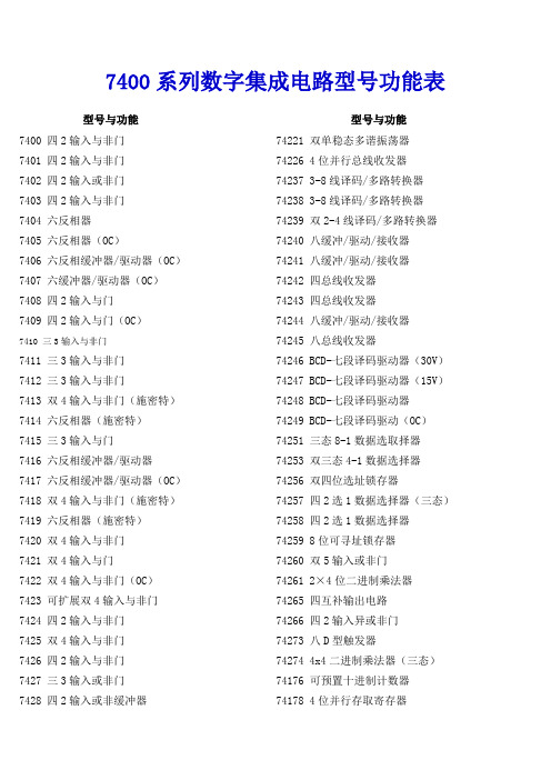
7400系列数字集成电路型号功能表型号与功能型号与功能7400 四2输入与非门7401 四2输入与非门7402 四2输入或非门7403 四2输入与非门7404 六反相器7405 六反相器(OC)7406 六反相缓冲器/驱动器(OC)7407 六缓冲器/驱动器(OC)7408 四2输入与门7409 四2输入与门(OC)7410 三3输入与非门7411 三3输入与非门7412 三3输入与非门7413 双4输入与非门(施密特)7414 六反相器(施密特)7415 三3输入与门7416 六反相缓冲器/驱动器7417 六反相缓冲器/驱动器(OC)7418 双4输入与非门(施密特)7419 六反相器(施密特)7420 双4输入与非门7421 双4输入与门7422 双4输入与非门(OC)7423 可扩展双4输入与非门7424 四2输入与非门7425 双4输入与非门7426 四2输入与非门7427 三3输入或非门7428 四2输入或非缓冲器74221 双单稳态多谐振荡器74226 4位并行总线收发器74237 3-8线译码/多路转换器74238 3-8线译码/多路转换器74239 双2-4线译码/多路转换器74240 八缓冲/驱动/接收器74241 八缓冲/驱动/接收器74242 四总线收发器74243 四总线收发器74244 八缓冲/驱动/接收器74245 八总线收发器74246 BCD-七段译码驱动器(30V)74247 BCD-七段译码驱动器(15V)74248 BCD-七段译码驱动器74249 BCD-七段译码驱动(OC)74251 三态8-1数据选取择器74253 双三态4-1数据选择器74256 双四位选址锁存器74257 四2选1数据选择器(三态)74258 四2选1数据选择器74259 8位可寻址锁存器74260 双5输入或非门74261 2×4位二进制乘法器74265 四互补输出电路74266 四2输入异或非门74273 八D型触发器74274 4x4二进制乘法器(三态)74176 可预置十进制计数器74178 4位并行存取寄存器7430 八输入与非门7431 延时单元电路7432 四2输入或非门7433 四2输入或非缓冲器7434 六缓冲器7436 四4输入或非门7437 四输入端与非缓冲器7438 双2输入与非缓冲器(OC)7431 延时单元电路7432 四2输入或非门7433 四2输入或非缓冲器7434 六缓冲器7436 四4输入或非门7437 四输入端与非缓冲器7438 双2输入与非缓冲器(OC)7440 双四输入端与非缓冲器7442 BCD-十进制译码器7443 余3码—十进制计数器7444 余3格雷码—十进制计数器7445 BCD-十进制译码/驱动器7446 BCD-七段译码驱动器(OC)7447 BCD-七段译码驱动器(OC,15V)7448 BCD-七段译码驱动器7449 BCD-七段译码驱动器7450 二2输入双与或非门7451 2/3输入双与或非门7452 四输入可扩展与或门7454 四输入与或非门7455 四4输入与或非门7458 2/3输入双与或非门7460 双4输入与扩展器7461 三3输入与扩展器74276 四J-K触发器74278 4位级联优先寄存器74279 四R—S锁存器74280 9位奇偶校验/发生器74281 4位并行二进制累加器74283 4位二进制全加器74284 4x4二进制并行乘法器74285 4x4二进制并行乘法器74290 十进制计数器74292 可编程分频器/数字定时器74293 4位二进制计数器74295 4位双向通用移位寄存器74297 数字锁相环74298 四2选1数据选择器74299 8位双向移位寄存器74320 晶体控制振荡器74321 晶体控制振荡器74322 带符号扩展的8位移位寄存器74323 8位双向移位寄存器74324 压控振荡器(双向输出)74325 双压控振荡器(双向输出)74326 双压控振荡器(双向输出)74327 双压控振荡器(单向输出)74340 八缓冲/线驱动器74341 八缓冲/线驱动器74344 八缓冲/线驱动器74347 BCD-七段译码/显示驱动器74348 三态8-3优先编码器74351 双8选1数据选择器(三态)74352 双4选1数据选择器(反相)74353 双4选1数据选择器(三态、反相)74354 8选1数据选择器(三态、地址锁存)7462 4输入与扩展器7463 六电流读出接口门7464 4/2/3/2输入与或非门(图腾柱)7465 4/2/3/2输入与或非门7468 双十进制计数器7470 与输入正沿J-K触发器7471 与输入R-S主从触发器7473 双J-K触发器7474 双D触发器7475 4位双稳态锁存器7476 双J-K触发器7477 4位双稳态锁存器7478 双J-K触发器7480 门输入全加器7482 2位二进制全加器7483 4位全加器7485 4位幅度比较器7486 四2输入异或门7490 4位十进制波动计数器7491 8位移位寄存器7492 12分频计数器7493 二进制计数器7494 4位移位寄存器7495 4位并入并出寄存器7496 5位移位寄存器7497 6位二进制同步系数乘法器74107 双J-K触发器74108 双J-K负边沿触发器74109 正沿触发双J-K触发器74110 与输入双J-K主从触发器74112 双J-K负边沿触发器74113 双J-K负边沿触发器74356 双8选1数据选择器(三态、地址锁存)74362 四相时钟发生/驱动器74363 8D锁存器(三态)74364 8D锁存器(三态)74365 六缓冲器/总线驱动器(三态、反相)74366 六缓冲器/总线驱动器(三态、74377 八 D触发器74378 六 D型触发器74379 四 D型触发器74381 算术逻辑单元/函数发生器74382 算术逻辑单元/函数发生器74384 8×1.2位补码乘法器74385 四串行加/减法器74386 四2输入异或门74390 双4位十进制计数器74393 双4位十进制计数器74395 4位级联优先移位寄存器(3态输出)74396 8位存储寄存器74398 四2选1数据选择器(双端输出)74399 四2选1数据选择器(单端输出)74412 多模式缓冲/锁存器74422 单可重触发单稳态多谐振荡器(双端输出)74423 双可重触发单稳态多谐振荡器(单端输出)74425 四门总线驱动器(三态)74426 四门总线驱动器(三态)74428 系统控制器/总线驱动器74438 系统控制器/总线驱动器74440 四3向总线收发器(OC)74441 四3向总线收发器(OC)74442 四3向总线收发器(三态)74443 四3向总线收发器(三态)74444 四3向总线收发器(三态)74114 双J-K负边沿触发器74116 双4位锁存器74120 双脉冲同步器74121 单稳态多谐振荡器74122 单稳态多谐振荡器74123 双稳态多谐振荡器74124 双压控振荡器74125 三态缓冲器74126 四3态总线缓冲器74128 双2输入端或非线驱动器74131 3-8线译码器74132 二输入与非触发器74133 13输入与非门74134 12输入与非门74135 4输入异或/异或非门74136 四2输入异或门74137 3-8线译码器74138 3-8线译码/转换器74139 双2-4线译码/转换器74140 双4输入非门线驱动器(50Ω)74141 BCD—十进制译码/驱动器74142 BCD计数/锁存、译码/驱动器74143 4位计数/7段译码显示驱动器74144 4位计数/7段译码显示驱动器(OC)74145 BCD—十进制译码/驱动器74147 10-4线优先编码器74148 8-3线优先编码器74149 8-3线优先编码器74150 16选1数据选择器74151 8选1数据选择器74152 8选1数据选择器74153 双4选1数据选择器74445 BCD—十进制译码/驱动器74447 BCD—7段译码/驱动器74448 四3向总线收发器(三态)74465 八总线缓冲器(同相门控、三态)74466 八总线缓冲器(反相门控、三态)74467 八总线缓冲器(同相门控、三态)74468 八总线缓冲器(反相门控、三态)74490 双4位十进制计数器74520 8位数值比较器74521 8位数值比较器74533 8位三态D型锁存器74534 8D触发器(三态、反相)74537 BCD—十进制译码(三态)74538 3—8线多路分配器(三态)74540 8位输出缓冲器(同相)74367 六缓冲器/总线驱动器(三态、反相)74368 六缓冲器/总线驱动器(三态、同相)74373 8D锁存器(三态)74374 8D触发器(三态)74375 4位双稳锁存器74376 四J-K触发器74568 可预置十进制同步可逆计数器(三态)74569 可预置二进制同步可逆计数器(三态)74573 8位三态输出D型锁存器74574 8 D触发器74580 8位三态锁存器74583 4位全加器(带超前进位)74589 8位输入串出移位寄存器74590 8位二进制计数器74594 8位移位寄存器74595 8位输入锁存输出移位寄存器74597 8位输入锁存输出移位寄存器74154 4-16线多路分配器74155 双2-4线分路分配器74156 双2-4线分路分配器(OC)74157 四2选1数据选择器(同相)74158 四2选1数据选择器(反相)74159 4-16线译码—多路分配器(OC)74160 同步BCD十进制计数器74161 4位二进制计数器74162 同步BCD十进制计数器74163 4位二进制计数器74164 8位串入并出移位寄存74165 8位移位寄存器74166 8位移位寄存器74167 BCD同步系数乘法器74168 4位可逆同步计数器74169 4位可逆同步计数器74170 4×4位寄存器堆74172 16位多通道寄存器堆(三态)74173 4D寄存器74174 6D寄存器74175 4D寄存器74180 9位奇偶校验/发生器74181 运算器/函数发生器74182 超前进位发生器74183 双进位保存全价器74184 BCD—二进制转换器74185 二进制—BCD转换器74189 64位随机存储器74190 可预置BCD十进制同步可逆计数器74191 二进制同步可逆计数器74192 同步BCD可逆计数器74193 二进制可逆计数器74620 8位三态总线收发器74621 8位总线收发器(OC)74622 8位总线收发器(OC)74623 8位三态总线收发器(三态)74624 压控振荡器74625 双压控振荡器(双相输出)74626 双压控振荡器(双相输出)74627 双压控振荡器(单相输出)74628 压控振荡器(双相输出)74629 双压控振荡器(单相输出)74638 8位总线收发器(OC、三态、反相)74639 8位总线收发器(OC、三态、同相)74640 8总线收发器(三态、反相)74641 8位总线收发器(OC、同相)74642 8位总线收发器(OC、反相)74643 8位总线收发器(三态、单反相)74644 8位总线收发器(OC、单反相)74645 8位总线收发器(三态、同相)74541 8位三态输出缓冲器74563 8D锁存器(三态、反相)74564 8D触发器(三态、反相)74691 可预置二进制同步计数器/寄存器74692 可预置十进制同步计数器/寄存器74693 可预置二进制同步计数器/寄存器74696 十进制同步可逆计数器74697 二进制同步可逆计数器74698 十进制同步可逆计数器(同步清零、三态)74699 二进制同步可逆计数器(同步清零、三态)74795 八总线缓冲器(同相门控)74796 八总线缓冲器(反相门控)74797 八总线缓冲器(同相4线、4线允许)74798 八总线缓冲器(反相4线、4线允许)74194 双向通用移位寄存器74195 并行存取移位寄存器74196 可预置十进制计数器74197 可预置二进制计数器74198 8位移位寄存器74199 8位移位寄存器74805 六2输入或非门驱动器74808 六二输入与门缓冲器74823 9位D触发器74827 十缓冲器(三态)74942 300波特率调制解调器(双电源)74943 300波特率调制解调器(单电源)。
HD-Power(7400手簿)操作说明书--放样
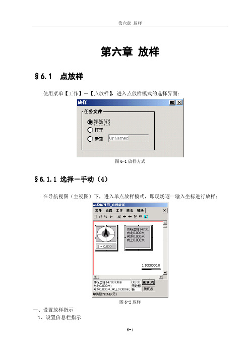
第六章放样§6.1 点放样使用菜单【工作】-【点放样】,进入点放样模式的选择界面:图6-1放样方式§6.1.1 选择-手动(4)在导航视图(主视图)下,进入单点放样模式,即现场逐一输入坐标进行放样;图6-2放样一、设置放样指示1、设置信息栏指示在导航视图(主视图)下,双击【Enter】键,弹出“图形菜单”,选择“放样正向”中的“正北”(图6-3);再执行“选项菜单”(导航视图下按【P】键),选择“放样指示”(图6-4);图6-3图形菜单图6-4选项菜单正北----目标点偏离GPS当前位置的南/北距、东/西距和高差图6-5放样信息栏放样时,移动GPS,使其偏离放样点的南/北距、东/西距在其误差范围内(在仪器标称精度内或工作精度内),最小值为1~2cm,该位置即为放样点位置。
2、打开导航图示图6-6导航图示按F4键(蓝色功能键+数字键4),显示/隐藏导航图示(导航图示在隐藏状态下,按F4键显示导航图示;导航图示在显示状态下,按F4键隐藏导航图示)图6-7放样导航图黑箭头所指方向:放样点方向灰箭头所指方向:GPS瞬时移动方向S:GPS与待放样点之间的距离放样时,移动GPS:(1)、使灰箭头所指方向和黑箭头所指方向重合,这样表明GPS移动方向正确(2)、使S后的距离值变小,直到其误差范围内(在仪器标称精度内或工作精度内),最小值为1~2cm,该位置即为放样点位置注:GPS如果没有移动时,灰箭头方向会四周乱指,这是因为RTK有1~2cm的误差所造成的;要正确指示GPS所移动的方向,则要使GPS向一个方向移动,这时灰箭头所指方向为GPS所移动的方向;3、打开放样指示图6-8放样指示(1)、按F5键(蓝色功能键+数字键5),显示/隐藏放样指示(放样指示在隐藏状态下,按F5键显示放样指示;放样指示在显示状态下,按F5键隐藏放样指示)(2)、设置“图形菜单”(在导航视图下,双击【Enter】键)中的“放样正向”为“正北”。
RTK求解参数(三参、四参、七参)

• 一般的:
• • • • 三参数:要求已知一个国家坐标点,精度随传输距离增加而减少 四参数:要求两个任意坐标点,精度在小范围内可靠 七参数:三个国家坐标点,精度高,对已知点要求严格 一步法:三个任意坐标点,在残差不大的情况下,精度可靠
• 投影讲解 一步法转换
五、校正参数
• 用于计算两坐标系统之间的平面、高程平移参数。通常 在以下两种情况,可以使用校正参数
空间直角坐标(X,Y,Z)
大地坐标(B,L,H) 投影正算 平面直角坐标(x,y,h) 平面转换 当地平面坐标(x,y)
RTK简易操作流程
• 以下只是软件的简易操作流程,详细使用步骤请参照接下来的详细说明。此 流程只是我们提供给的一种解决方案,在熟练使用本软件后,可以不依照此 步骤操作。在作业过程中,通常的使用方法为:
RTK求解参数
罗禹
参数的概念
1、由于GPS所采用的坐标系为WGS-84坐标系,而 在我们国家,实际的工作中所使用的都是BJ-54,国 家-80、或地方坐标系, 因此存在WGS-84和当地坐标系统之间的转换问题。 2、参数转换一般分两种形式: 平面坐标系之间的转换:四参数、校正参数 椭球体之间的转换: 三参数,七参数
谢谢
• 1、只有一个BJ-54、国家-80坐标或只有一个和WGS-84 坐标系旋转很小的坐标系下的坐标,基准站架设好后, 移动站可以直接到一个已知点,点击【点校验】--【计 算】,采集当前点的WGS-84坐标,输入已知点的当地 坐标,点击【计算】,得出已知坐标和当前坐标的改正 量dx、dy、dz,点击【应用】可应用校验参数,应用后 所采点的坐标将自动通过校验参数改正为和已知点同一 坐标系统的坐标。
不同(椭球)坐标系的转换流程
几种椭球转换模型的特点: 1.三参数法: 七参数方法的简化,只取X平移,Y平移,Z平移。 运用于信标,SBAS,固定差改正以及精度要求不高的地方, 用于RTK模式下,作用距离在5km范围较平坦的地方(基站开机模式) 2.布尔莎七参数法: 标准的七参数方法,使用X,Y,Z平移,X,Y,Z旋转,K尺度 作用范围较大和距离较远,通常用于RTK模式或者RTD模式的 WGS84到北京54和国家80的转换,已知点要三个以上,要求较高。 3.四参数+高程拟合: 使用X,Y平移,a旋转,k尺度还有高程拟合参数 也是RTK常用的一种作业模式,通过四参数完成WGS84平面到当地平面 的转换,利用高程拟合完成WGS84椭球高到当地水准的拟合。 4.一步法 参数形式和标准七参数一样, X,Y,Z平移,X,Y,Z旋转,K尺度 可以一步完成WGS84到当地地方坐标系统的转换工作。也许要三个以上 WGS84点和当地地方坐标。 5、校正参数 使用X,Y平移,小范围使用
富士通打印机DL7400PRO指南说明书
Power requirements
Dimensions
Width x Depth x Height
Weight
Acoustic noise level
MTBF (mean time between failures)
Print head life
Ribbon life Black
24-wire dot matrix, bi-directional
Heavy duty and high-speed printing FUJITSU Printer Technical Specifications
Specifications Printing technology
Printing speed
Resolution Character sets
Resident fonts Scalable fonts Word processing functions Input buffer Printing width Line feed speed Form feed speed Number of copies Paper thickness Paper width
600 cps (10cpi) 606/505 432/360 288/240 144/120
128
60 6 1+7 high copy mode 0.57 55 – 420 102 – 420 output: ≤ 120W average; standby: ≤ 1W 600 x 350 x 290 18,5 55 (soundproof cover) 20,000 400 5
Heavy duty and high-speed printing
HD-Power(7400手簿)操作说明书--文件类型介绍及格式说明5P

第十二章文件类型介绍及格式说明§12.1 文件类型介绍项目文件:*.prj轨迹点记录:*.rec控制点坐标库文件/水准点坐标库文件:*.knw/*.hkw放样点坐标库文件:*.tsk线路文件: *.rod线段文件:*.sct纵断面数据文件:*.ver横断面数据:*.tra七参数转换文件:Temp7.c47转换参数转换文件:Temp4.c47§12.2 文件格式说明HaidaRtk文档说明文件1、(*.prj) 项目文件文件内容:(“//”后为说明文字)[VER 1.00 (*.prj)] //文件头Datum Name:WGS-84 //坐标系统部分:系统名称、长半轴、扁率a:6378137.00000000000 //及七参数、1/e:298.257223563407On:0SHIFT X:0.00000000000SHIFT Y:0.00000000000SHIFT Z:0.00000000000ROTATION A:0.00000000000ROTATION B:0.00000000000ROTATION C:0.00000000000K PPM:0.00000000000Projecture: //投影参数L0:114:00:00.000SCALE:1.00000000000CONSTX:0.00000000000CONSTY:500000.00000000000UndualMode:USERUserValue:0.000000TRANSFORM:0 //转换参数(四参数)SHIFT X:0.00000000000SHIFT Y:0.00000000000ROTATION:0.00000000000SCALE:1.00000000000HEIGHT TRAN: //高程改正(仅作为预留)Mode:0Normal:0.0000 //固定差A:0.0000 //平面拟合B:0.0000C:0.0000A0:0.0000 //曲面拟合A1:0.0000A2:0.0000A3:0.0000A4:0.0000A5:0.0000IsRemote:-1 //-1-预设,0-基准站,1-流动站BASESTATION: //当前采用的基准站坐标与参数StaName:ANT H:0.0000RTKMODE:RTKRTCM-SC:RTCASTAR-MASK:10STAR-NUM:8ROVE: //当前采用的移动站坐标与参数RTKMODE:RTKRTCM-SC:RTCASTAR-MASK:10RECEIVER: //接收机信息MODEL:HD5800NBORD:NOVATELCF-Port:COM2CF-Baud:9600CF-Delay:1Navi-Type:BESTPOSNavi-Delay:1AntH:0.00000000000 //移动站信息PreH:20.00000000000PreS:5.00000000000SV:ffffffffMode:5 //放样参数IsRoadSect:0RoadNum:0RecName:\ipsm\aaaaa\aaaaa.recRoadName:SectName:2、(*.knw/*.hkw) 控制点坐标库/水准点坐标库[VER 1.01 (*.knw)]z10,0,0,0.40385416108,1.97807537708,74.0801,0.0000,z13,0,3,2560422.96478472280,380716.26206874562,74.0801,0.0000,z12,0,2,2560422.96478472280,380716.26206874562,74.0801,0.0000,z11,0,1,0.40385416108,1.97807537708,74.0801,0.0000,格式说明:点名,使用计数,控制点坐标类型,X/B,Y/L,H,高程异常,注记3、(*.rec) 轨迹点记录[VER 1.02 (*.rec)]ZHD1,2002-05-13|09:45:17,2560129.438,431912.549,74.380,0.000,0.000,23:08:21.80028N,113:20:06.73439E,74.380,0,,NARROW_INT50,0.000,0.000,,089117,1004 ZHD2,2002-05-13|09:45:17,2560147.883,431915.478,74.480,0.000,0.000,23:08:22.40028N,113:20:06.83439E,74.480,0,,NARROW_INT50,0.000,0.000,,089117,1967 19ZHD3,2002-05-13|09:45:17,2560144.742,431929.689,74.780,0.000,0.000,23:08:22.30028N,113:20:07.33439E,74.780,0,,NARROW_INT50,0.000,0.000,,089117,8390 719ZHD4,2002-05-13|09:45:17,2560157.073,431924.055,74.080,0.000,0.000,23:08:22.70028N,113:20:07.13439E,74.080,0,,NARROW_INT50,0.000,0.000,,089117,2516 7935格式说明:每个记录点为一行,在word中可能会看到自动换行,请注意区分点名, 记录时间, GC’X, GC’Y, GC’H,记录时天线高,高程改正,WGS-84’B, WGS-84’L, //WGS-84’H,是否是控制点,控制点点名,解状态, 平面中误差, 高程中误差, 注记, GPS时间,地物属性4、(*.ver) 纵断面数据1010.00,10000000000.0000,0.4000,0,10000000000.00,123.121050.00,0.4000,0.2000,1,200.00,111.111100.00,0.2000,0.4000,1,100.00,24.34变坡点,坡度1,坡度2,竖曲线(T/F),半径,变坡点高程10000000000.0000代表无穷大5、(*.tra) 横断面数据a)横断面记录文件采用二进制数据文件,恕不提供格式;b)2.02版开始在横断面视图的选项菜单中支持横断面数据导出,目前有三种格式,以下为每种格式下的一条记录:(1)相对于前一点高差(*.txt),格式说明:1.行一:中桩里程,断链号2.行二:左1D,左1H(相对于中桩地面高程),左2D(相对于左1D),左2H(相对于左1H)…3.行三:右1D,右1H(相对于中桩地面高程),右2D(相对于右1D),右2H(相对于右1H)…(2)相对于中桩设计高差(*.txt),格式说明:1.行一:中桩里程,断链号,设计高程,地面点高差(地面点高程-设计高程)2.行二:左1D,左1H(相对于中桩设计高程),左2D,左2H(相对于中桩设计高程)…3.行三:右1D,右1H(相对于中桩设计高程),右2D,右2H(相对于中桩设计高程)…(3)纵断面地形(*.txt),格式说明:1. 1. 行一:中桩里程,断链号,设计高程,地面点高差(地面点高程-设计高程)6、(*.tsk) 放样点库文件[VER 1.03(*.tsk)]name1, 2560217.015, 432138.098, 73.580name2, 2560317.015, 432238.098, 73.580name3, 2560217.015, 432138.098, 73.580格式说明:放样点名,工程X,工程Y,工程H7、交点表文件(*.txt)交点编号,交点里程,交点X,交点Y,缓曲长1,圆曲半径, 缓曲长2,回头曲线,转角,切线长1,切线长2,曲线总长,到下一点的方位角BP,14700,3165357.931,518106.909,,,,,,,,,JD7,15202.259,3165094.100,517679.525,120,700,,,,,,,JD8,16514.728,3164069.59,516855.055,150,1030,,,,,,,JD9,18090.282,3163213.613,515528.597,250,2250,,,,,,,JD10,19483.523,3162622.904,514266.120,350,2400,,,,,,,JD11,21304.711,3161247.977,513049.522,200,1235,,,,,,,JD12,22642.893,3160642.585,511849.194,200,1700,,,,,,,JD13,23498.532,3160462.271,511010.105,90,1150,,,,,,,JD14,24503.681,3160104.619,510070.334,100,1260,,,,,,,JD15,25599.394,3159567.086,509115.084,200,1015,,,,,,,JD16,27211.972,3159340.666,507513.458,200,1030,,,,,,,JD17,28237.328,3159640.472,506524.711,200,1200,,,,,,,EP,29406.331,3159287.139,505386.602,,,,,,,,,格式说明:第一行为表头,必须存在;请注意逗号的数量,建议使用Microsoft Excel 编辑。
中海达rtk使用说明

一.开关GPS主机二.GPS工作模式的设置三.电台频道设置四.GPS主机面版灯含义五.Dolphin手簿操作说明六.架设基准站七.手簿与GPS主机的连接(蓝牙无线连接)八.手簿程序的操作流程(转换参数配合高程拟合法)1.新建项目2.设置基准站3.断开手簿与基准站GPS主机4.添加控制点5.连接手簿与移动站GPS主机6.移动站设置7.采集碎部点坐标8.求解转换参数和高程拟合参数9.点放样10.测量成果的导出九.附录1.卫星检验2.接收机复位3.设置高程拟合模式说明4.连接程序的安装5.手簿常用快捷键功能一览表6.求解七参数的操作7.计算两点间距离8.计算校正参数9.直线放样10.HD-POWER操作程序的升级一、开关GPS主机1、按电源键1秒,开机2、按电源键3秒,关机二、控制面板按键图解主机控制面板有按键两个:F键(功能键)和电源键,指示灯3个,分别为电源、卫星、状态。
按键和指示灯的功能和含义分别是:V8 CORS RTK 系统面板控制和指示说明图2 主机控制面板按键图工作方式: ●亮○灭方式卫星灯(单绿灯)信号灯(双灯之绿灯)基准站● ○移动站○ ●静态● ●类型卫星灯(单绿灯)信号灯(双灯之绿灯)内置UHF ● ○内置GSM ○ ●外挂● ●电台频道:频道电源灯(单红灯) 卫星灯(单绿灯)信号灯(双灯之绿灯)数据灯(双灯之红灯)0 ○ ○ ○ ○1 ● ○ ○ ○2 ○ ● ○ ○3 ● ● ○ ○4 ○ ○ ● ○5 ● ○ ● ○6 ○ ● ● ○7 ● ● ● ○8 ○ ○ ○ ●9 ● ○ ○ ●A ○ ● ○ ●B ● ● ○ ●C ○ ○ ● ●D ● ○ ● ●E ○ ● ● ●F ● ● ● ●控制面板操作说明:一、功能键操作说明:1、双击F (间隔>0.2S,小于1S),进入“工作方式”设置,有“基站”、“移动站”、“静态”三种工作模式选择。
2、长按F大于3秒进入“数据链设置”,有“UHF”、“GSM”、“外挂”三种数据链模式选择。
DS7400或IP7400操作培训简明手册

DS7400或IP7400操作培训简明手册及MTSW软件详细设置一、键盘认识二、键盘常用操作指令(说明:PIN 代表密码,默认为1234)强制布防:当系统有故障,键盘显示,表示有交流电未接、接地不正确、防区故障等现象。
在未排除系统故障前,可以用强制布防的方法来对系统进行布防。
强制布防方法:PIN(密码)+On(布防)+Bypass(旁路)三、系统时间设置DS7400XI 报警主机可储存400 条事件记录,可以记录各事件发生的时间。
但在系统调试时,必须预先设定好日期和时间。
方法是:3.1 更改日期3.2 更改时间四、更改个人密码DS7400XI 可以增加至90 个个人密码(V4.0 可增加至200 个),但只有一个是主码。
主码的设置在编程部分中设定,只有知道主码后,才能增加其他密码。
密码有6 个级别,分别表示:0:主码,最高权限1:有不能更改其他密码外的所有权限2:能旁路和布防/撤防3:只能布防4:临时密码,在规定的时间内有效5:胁持码6:入口码,可控制可编程输出口,输出口有一个10 秒的脉冲输出更改密码步骤五、软件的设置与使用1、软件登入(用户名;ADMIN,密码:ADMIN)如下图2、工作主界面,如下图3、鼠标点菜单“管理---参数设置”,如下图4、进入下面的工作界面5、点菜单“连接---中心设备”6、点“增加中心设备”按钮。
(根据设备类型IP7400、DS7400、MTR、D6600/D6100或DSR32C选择增加(一项或多项))A、IP7400报警主机如下图B、DS7400报警主机如下图C、D6600/D6100报警主机D、MTR报警主机E、DSR32C继电器联动F、数据传递(网络转发方式或与视频联动)六、举例DS7400报警主机的周界设置;点菜单“用户----周界设置”终端设备信息(如:DS7457、DS7460、DS7432等)周界信息(与终端设备信息对应)防区联动DSR32C输出(点下图:周界联动命令设置)然后出现下图点“应用程序”按钮的下三角箭头,选中“数据传递或控制”点“新命令”出现下图点“浏览(B)”出现下图(实际情况与下图不同)鼠标选中“中心设备--2”或双击;出现下图选中“字符串输出”,如下图然后按下图填写需联动的继电器口编号,如下图上图表示当前设置的防区联动2号口输出七、周界地图设置点菜单“用户--用户组地图设置”,出现下图点“设置地图”按钮出现下图选中预先制作好的图纸,图纸默认放在安装的目录下面,如:周界定位,图例(选好图后,点周界定位,鼠标变成一支笔,可在图纸上画一条直线)八、设置好后,退出主界面,看一下模拟报警情况点菜单“系统――模拟报警”,如下图选中周界报警,点“周界名称”后面“…“的位置出现下图选中一个防区,如点“选择”按钮出现点发送,出现下面的效果八、窗口显示内容的调整,例点菜单“窗口—未处理警情列表设置”出现下图可调整级别、时间、名称……的显示顺序及是否显示九、自动注销时间调整及标题设置十、用户名修改……。
RTK操作过程

图根控制计算说明观测手段:使用1台NIKON DTM-352全站仪观测部分图根导线网,配合使用中海达珠峰HD6000 GPS RTK 2台套进行动态测量。
内业计算:使用控制网平差软件NA V2.96 For Windows95/98/2000 和中海达公司的GPS随机软件进行图根导线网平差和RTK数据的下载。
坐标系统:近似1954年北京坐标系。
高程系统:1985国家高程基准。
RTK操作过程简介:勐龙测区在RTK测量时将GPS03点作为已知点架设基准站,然后分别在GPS07、GPS010、GPS12、GPS20四点上架设移动站测定它们在没有转换参数时相对于基准站的固定解,再利用这五组对应坐标求得相相对于基准站的固定解坐标到测区坐标的转换参数。
4.1、基准站设置基站架设要满足下列要求:○1高度角在15度以上开阔,无遮挡物;○2无电磁波干扰(200米内没有微波站、雷达站、手机信号站等50米内不能有高压线);○3位置比较高。
注:考虑到安全等方面的因素,并且对GPS03周围几个无线电发射源对架设基站的影响进行评估和检查后,最后确定将GPS03作为测区RTK测量时架设基准站的已知点。
将基准站GPS接收机架设在GPS03点上对中、整平、量取天线高后,打开GPS 接收机电源,在接收机面板上设置,使其处于内置GPRS电台的基准站模式。
等卫星指示灯处于稳定状态不少于3分钟后打开7400手簿,运行界面上的“Haidartk”程序。
这时,7400手簿会自动和GPS接收机进行连接。
如果连接状态显示:脱机态,则手簿与GPS接收机没有连接好初始化,则手簿与GPS接收机已连接好,但GPS还没有收到卫星基准站,则手簿与GPS接收机已连接好,GPS收到卫星移动站,则手簿与GPS接收机已连接好,GPS收到卫星当连接状态显示基准站或移动站时,使用【文件】—【新建项目】,在“选择新建项目的方式”对话框中选【向导】。
系统会引导你一步一步完成所有必要的设置。
7400系列和7400终极系列驱动包装安装、维护和零部件手册说明书

For other service manuals visit our website at:/service_manuals.aspDORNER MFG. CORP .INSIDE THE USA OUTSIDE THE USAP .O. Box 20 • 975 Cottonwood Ave.TEL: 1-800-397-8664TEL: 262-367-7600Hartland, WI 53029-0020 USA FAX: 1-800-369-2440FAX: 262-367-5827851-596 Rev. C7400 Series and 7400 UltimateSeries Drive PackagesInstallation, Maintenance and Parts ManualHorizontal Mount Vertical Mount Nose Bar MountDorner Mfg. Corp.2851-596 Rev. C7400 Series and 7400 Ultimate Series Drive PackagesTable of ContentsIntroduction......................................................................... 2Warnings – General Safety.................................................. 3Product Description............................................................. 4Specifications...................................................................... 47400 Series Gearmotor Mounting Package Models........ 47400 Series Gearmotor Specifications............................. 5Fixed Speed Gearmotor................................................ 5Three Phase Gearmotor................................................ 5Installation........................................................................... 6Required Tools................................................................. 6Drive Package Installation............................................... 6Horizontal Drive Package............................................ 6Vertical Drive Package................................................. 8Nose Bar Drive Package .. (10)Preventive Maintenance and Adjustment.......................... 12Required Tools............................................................... 12Checklist ........................................................................ 12Gear Reducer Replacement............................................ 12Motor Replacement........................................................ 14Service Parts....................................................................... 16Horizontal Drive............................................................. 16Vertical Drive................................................................. 17Nose Bar Drive............................................................... 18Gearmotor Assembly...................................................... 19Return Policy. (20)IntroductionUpon receipt of shipment:•Compare shipment with packing slip. Contact factory regarding discrepancies.•Inspect packages for shipping damage. Contact carrier regarding damage.Accessories may be shipped loose.• See accessory instructions for installation.The Dorner Limited Warranty applies.Dorner 7400 Series conveyors have patents pending.Dorner reserves the right to make changes at any time without notice or obligation.Dorner has convenient, pre-configured kits of Key Service Parts for all conveyor products. These time saving kits are easy to order, designed for fast installation, and guarantee you will have what you need when you need it. Key PartsIntralox is a registered trademark of Laitram L.L.C. in the United States and /or other countries.CAUTIONSome illustrations may show guardsremoved. DO NOT operate equipment without guards.851-596 Rev. C3Dorner Mfg. Corp.7400 Series and 7400 Ultimate Series Drive PackagesWarnings – General SafetySEVERE HAZARD!KEEP OFF CONVEYORS. Climbing, sitting, walking or riding on conveyor will result in death or serious injury.EXPLOSION HAZARD!•DO NOT OPERATE CONVEYORS IN AN EXPLOSIVE ENVIRONMENT. The electric gearmotor generates heat and could ignite combustible vapors.•Failure to comply will result in death or serious injury.WARNINGCRUSH HAZARD!•DO NOT place hands or fingers inside the conveyor while it is running.•DO NOT wear loose garments whileoperating the conveyor. Loose garments can become caught up in the conveyor.•Failure to comply could result in serious injury.WARNINGCRUSH HAZARD!•SUPPORT CONVEYOR SECTIONS PRIOR TO LOOSENING STAND HEIGHT OR ANGLE ADJUSTMENT SCREWS.•Loosening stand height or angleadjustment screws may cause conveyor sections to drop down, causing serious injury.WARNINGSEVERE HAZARD!LOCK OUT POWER before removing guards or performing maintenance. Exposed moving parts can cause serious injury.WARNINGBURN HAZARD!DO NOT TOUCH the motor while operating, or shortly after being turned off. Motors may be HOT and can cause serious burn injuries.WARNINGPUNCTURE HAZARD!Handle drive shaft keyway with care. It may be sharp and could puncture the skin, causing serious injury.WARNINGSEVERE HAZARD!•Dorner cannot control the physicalinstallation and application of conveyors. Taking protective measures is the responsibility of the user.•When conveyors are used in conjunction with other equipment or as part of a multiple conveyor system, CHECK FOR POTENTIAL PINCH POINTS and other mechanical hazards before system start-up.•Failure to comply could result in serious injury.Dorner Mfg. Corp.4851-596 Rev. C7400 Series and 7400 Ultimate Series Drive PackagesProduct DescriptionRefer to (Figure 1) for typical gearmotor assembly components.Figure 1Specifications7400 Series Gearmotor Mounting Package ModelsExample:* Refer to “Ordering and Specifications” Catalog for details.Typical Components1Conveyor 2Mounting bar 3Motor 4Gear reducer5Gear reducer mounting bracketNOTEthe vertical drive package is shown above, but the horizontal and nose bar drive packages contain similar components.253417400 Series and 7400 Ultimate Series Drive Packages Specifications7400 Series Gearmotor SpecificationsFixed Speed Gearmotor Three Phase Gearmotor Singe Phase Three PhaseOutput Power0.50 hp (0.37 kW).50 hp (.37 kW) /1 hp (.74 KW)/ 1.5 hp (1.11 kW) Input Voltage115 V A.C.208 - 230 / 460 V.A.C.Input Frequency60 Hz 6 – 60 HzMotor RPM22 - 4422 - 233Gearmotor Ratios5:1,7:1,10:1,15:1,20:1,30:1,40:1,60:1,80:1Frame Size NEMA 56 CMotor TypeT otally Enclosed, Non-ventilated(Except 1.5 hp Stainless Steel Gearmotor = T otally Enclosed, Fan Cooled)* Refer to “Ordering and Specifications” Catalog for details.Part Number ft/min m/min RPM in•lb N • m74M080HS4(vp)FN20 6.12235640.274M060HS4(vp)FN278.22944249.974M040HS4(vp)FN4112.54448654.974M030HS4(vp)FN5416.55848755.074M020HS4(vp)FN8124.78740746.074M015HS4(vp)FN10933.211747053.174M010HS4(vp)FN16450.017544249.974M007HS4(vp)FN21866.423336040.774M005HS4(vp)FN325100.035033738.1Part Number ft/min m/min RPM in•lb N • m74M080HS4(vp)EN 2 – 200.6 - 6.12235640.274M060HS4(vp)EN 3 – 270.9 – 8.22944249.974M040HS4(vp)EN 5 – 41 1.3 – 12.54448654.974M030HS4(vp)EN 6 – 54 2.0 - 16.55848755.074M020HS4(vp)EN9 – 81 2.6 – 24.78740746.074M015HS4(vp)EN11 – 109 3.4 – 33.211747053.174M010HS4(vp)EN17 – 164 5.2 – 50.017544249.974M007HS4(vp)EN22 - 218 6.7 – 66.423336040.774M005HS4(vp)EN34 - 32810.4 - 100.035033738.1NOTEContact the factory for details about beltspeeds other than those listed.851-596 Rev. C5Dorner Mfg. Corp.Dorner Mfg. Corp.6851-596 Rev. C7400 Series and 7400 Ultimate Series Drive PackagesInstallationRequired Tools•5/16 wrench•16 mm wrench (nose bar drive mount only)• 4 mm hex wrench •Large flat-head screwdriver •Torque wrenchDrive Package InstallationHorizontal Drive PackageHorizontal Drive Mounting PositionsFigure 2Typical Horizontal Drive Package Components (Figure 3)Figure 31.Insert the drive spindle key (Figure 4,item 1) into the drive spindle keyway (Figure 4,item 2).Figure 4WARNINGSEVERE HAZARD!LOCK OUT POWER before removing guards or performing maintenance. Exposed moving parts can cause serious injury.WARNINGPUNCTURE HAZARD!Handle drive shaft keyway with care. It may be sharp and could puncture the skin, causing serious injury.1Cover 2Cover bracket3Hex head cap screw 5/16 - 18 x .50 (x4) 4Gear reducer bent mounting bar (x2) 5Horizontal drive spacer6Horizontal gear reducer mounting bracket 7Gearmotor assembly8Hex head cap screw 5/16 - 18 x 2 9Hex head cap screw 5/16 - 18 x 1.25 (x4) 10Hex head cap screw 5/16 - 18 x 2127400 Series and 7400 Ultimate Series Drive Packages Installation2.Slide the gearmotor assembly (Figure5,item1) ontothe drive spindle (Figure5,item2).Figure53.Attach the upper gear reducer mounting bar(Figure6,item1) to the gearmotor assembly(Figure6,item2).Figure64.Attach the lower gear reducer mounting bar to thegearmotor assembly.5.Tighten the drive spindle fasteners (Figure 7,item1)located on the inside and outside of the gearmotor usinga hex wrench (Figure7,item2).Figure7Figure87.Remove the drainage plugs (Figure9,item1) on thebottom side of the motor.Figure912122111851-596 Rev. C7Dorner Mfg. Corp.Dorner Mfg. Corp.8851-596 Rev. C7400 Series and 7400 Ultimate Series Drive PackagesInstallationVertical Drive PackageVertical Drive Mounting PositionsFigure 10Typical Vertical Drive Package Components (Figure 11Figure 111.Insert the drive spindle key (Figure 12,item 1) into the drive spindle keyway (Figure 12,item 2).Figure 122.Slide the gearmotor assembly (Figure 13,item 1) onto the drive spindle (Figure 13,item 2).WARNINGSEVERE HAZARD!LOCK OUT POWER before removing guards or performing maintenance. Exposed moving parts can cause serious injury.WARNINGPUNCTURE HAZARD!Handle drive shaft keyway with care. It may be sharp and could puncture the skin, causing serious injury. 1Cover 2Cover bracket3Hex head cap screw 5/16 - 18 x .50 (x4) 4Gear reducer horizontal mounting bar (x2) 5Vertical gear reducer mounting bracket 6Hex head cap screw 5/16 - 18 x 1.25 (x6) 7Gearmotor assembly12851-596 Rev. C9Dorner Mfg. Corp.7400 Series and 7400 Ultimate Series Drive PackagesInstallationFigure 133.Attach the gear reducer mounting bars(Figure 14,item 1) to the gear reducer mounting bracket (Figure 14,item 2).Figure 144.Attach the gearmotor assembly (Figure 14,item 3) to the gear reducer mounting bars (Figure 14,item 1).5.Tighten the drive spindle fasteners (Figure 15,item 1) located on the inside and outside of the gearmotor using a hex wrench (Figure 15,item 2).Figure 15Figure 167.Remove the drainage plugs (Figure 17,item 1) on the bottom side of the motor.Figure 17122132111Dorner Mfg. Corp.10851-596 Rev. C7400 Series and 7400 Ultimate Series Drive PackagesInstallationNose Bar Drive PackageNose Bar Drive Mounting PositionsFigure 18Typical Nose Bar Drive Package Components (Figure 19)Figure 191.Attach the gear reducer mounting posts(Figure 20,item 1) to the nose bar side plate (Figure 20,item 2).Figure 202.Insert the drive spindle key (Figure 21,item 1) into the drive spindle keyway (Figure 21,item 2).WARNINGSEVERE HAZARD!LOCK OUT POWER before removing guards or performing maintenance. Exposed moving parts can cause serious injury.WARNINGPUNCTURE HAZARD!Handle drive shaft keyway with care. It may be sharp and could puncture the skin, causing serious injury.1Cover 2Cover bracket3Hex head cap screw 5/16 - 18 x .50 (x4) 4Nose bar gear reducer mounting post (x2) 5Hex head cap screw 5/16 - 18 x 1.25 (x4) 6Hex head cap screw M10 - 1.5 x 16 mm (x2) 7Gearmotor assembly21851-596 Rev. C11Dorner Mfg. Corp.7400 Series and 7400 Ultimate Series Drive PackagesInstallationFigure 213.Slide the gearmotor assembly (Figure 22,item 1) onto the drive spindle (Figure 22,item 2).Figure 224.Attach the gearmotor assembly (Figure 23,item 1) to the gear reducer mounting posts (Figure 23,item 2).Figure 23 5.Tighten the drive spindle fasteners (Figure 24,item 1) located on the inside and outside of the gearmotor using a hex wrench (Figure 24,item 2).Figure 25Remove the drainage plugs (Figure 26,item 1) on the bottom side of the motor.Figure 2612122111Dorner Mfg. Corp.12851-596 Rev. C7400 Series and 7400 Ultimate Series Drive PackagesPreventive Maintenance and AdjustmentRequired Tools•5/16 wrench • 4 mm hex wrench •Large flat-head screwdriverChecklist•Keep service parts on hand. Refer to the "Service Parts" section starting on page16 for recommendations.•Replace any worn or damaged parts.Gear Reducer Replacement1.Remove the bolts that connect the motor (Figure 27,item 1) to the gear reducer (Figure 27,item 2).Figure 272.Detach the motor (Figure 28,item 1) from the gear reducer (Figure 28,item 2) and set the motor aside.Figure 28WARNINGSEVERE HAZARD!LOCK OUT POWER before removing guards or performing maintenance. Exposed moving parts can cause serious injury.WARNINGBURN HAZARD!DO NOT TOUCH the motor while operating, or shortly after being turned off. Motors may be HOT and can cause serious burn injuries.12WARNINGCRUSH HAZARD!•SUPPORT MOTOR PRIOR TO LOOSENING THE BOLTS.•Loosening motor bolts may cause it to drop down, causing serious injury.NOTEBe sure to retain the motor output shaft key.12851-596 Rev. C13Dorner Mfg. Corp.7400 Series and 7400 Ultimate Series Drive PackagesPreventive Maintenance and Adjustment3.4.Figure 305.Unbolt the gear reducer mounting bars /posts (Figure 31,item 1) from the gear reducer(Figure 31,item 2) (horizontal drive shown in figure).Figure 318.Insert the gearmotor output shaft key(Figure 33,item 1) into the gearmotor output shaft keyway (Figure 33,item 2).Figure 339.Connect the new gear reducer to the motor.12112PUNCTURE HAZARD!Handle drive shaft keyway with care. It may be sharp and could puncture the skin, 1212Dorner Mfg. Corp.14851-596 Rev. C7400 Series and 7400 Ultimate Series Drive PackagesPreventive Maintenance and AdjustmentFigure 3410.Reinstall the gearmotor assembly. Refer to "DrivePackage Installation" starting on page 6.Motor ReplacementFigure 352.Refer to the wiring diagram (Figure 36,item 1) on the inside of the junction box cover.Figure 363.Loosen the wire nuts and disconnect the wires.4.Loosen the cord grip and remove the cord.WARNINGSEVERE HAZARD!LOCK OUT POWER before removing guards or performing maintenance. Exposed moving parts can cause serious injury.WARNINGBURN HAZARD!DO NOT TOUCH the motor while operating, or shortly after being turned off. Motors may be HOT and can cause serious burn injuries.1121851-596 Rev. C15Dorner Mfg. Corp.7400 Series and 7400 Ultimate Series Drive PackagesPreventive Maintenance and AdjustmentRemove the bolts that connect the motor Figure 376.Detach the motor (Figure 38,item 1) from the gear reducer (Figure 38,item 2).Figure 38Figure 39Align the motor output shaft key with the access hole in the gear reducer and connect the new motor to the gear reducer.9.Rewire the motor and attach the junction box cover.CRUSH HAZARD!SUPPORT MOTOR PRIOR TO LOOSENING Loosening motor bolts may cause it to drop down, causing serious injury.1212121Dorner Mfg. Corp.16851-596 Rev. C7400 Series and 7400 Ultimate Series Drive PackagesService PartsHorizontal DriveItem Part Number Description1807-1454Cover2500492Cover Bracket3906-067SS Hex Head Cap Screw, 5/16-18 x .50 4500380Gear Reducer Mounting Bent Bar 5500379Motor Mounting Bracket (7400 Series)501193Motor Mounting Bracket (7400 Ultimate Series)6906-061SS Hex Head Cap Screw,5/16-18 x .757500375Horizontal Drive Spacer 8906-072SS Hex Head Cap Screw,5/16-18 x 2.509906-070SS Hex Head Cap Screw,5/16-18 x 1.1210807-1458Set Screw CollarItem Part Number Description7400 Series and 7400 Ultimate Series Drive Packages Service PartsVertical DriveItem Part Number Description1807-1454Cover2500492Cover Bracket3906-067SS Hex Head Cap Screw, 5/16-18 x .50 4500381Vertical Drive Bent Bar 5500379Motor Mounting Bracket(7400 Series)501193Motor Mounting Bracket(7400 Ultimate Series) 6906-070SS Hex Head Cap Screw,5/16-18 x 1.127807-1458Set Screw CollarItem Part Number Description851-596 Rev. C17Dorner Mfg. Corp.Dorner Mfg. Corp.18851-596 Rev. C7400 Series and 7400 Ultimate Series Drive PackagesService PartsNose Bar DriveItem Part Number Description1807-1454Cover2500492Cover Bracket3906-067SS Hex Head Cap Screw, 5/16-18 x .50 4500485Nose Bar Gear Reducer Mounting Posts (7400 Series Only) 5906-070SS Hex Head Cap Screw,5/16-18 x 1.126961016MSS Hex Head Cap Screw,M10-1.5x16 mm (7400 Series Only) 7807-1458Set Screw Collar8500280Side Plate (7400 Series)501390Side Plate AssemblyA-Position (7400 Ultimate -Straight Conveyors)501395Side Plate AssemblyA-Position (7400 Ultimate -Curve Conveyors)501491Side Plate AssemblyD-Position (7400 Ultimate -Straight Conveyors)501493Side Plate AssemblyD-Position (7400 Ultimate -Curve Conveyors)Item Part Number Description7400 Series and 7400 Ultimate Series Drive Packages Service PartsGearmotor Assembly123Part Number Description Item Part Number Description851-596 Rev. C19Dorner Mfg. Corp.Dorner Mfg. Corp. reserves the right to change or discontinue products without notice. Allproducts and services are covered inaccordance with our standard warranty. All rights reserved. © Dorner Mfg. Corp. 2008DORNER MFG. CORP.975 Cottonwood Ave., PO Box 20 Hartland, WI 53029-0020 USAUSATEL 1-800-397-8664 (USA)FAX 1-800-369-2440 (USA)Internet: Outside the USA:TEL 1-262-367-7600FAX 1-262-367-5827851-596 Rev. C Printed in U.S.A.Return PolicyReturns must have prior written factory authorization or they will not be accepted. Items that are returned to Dornerwithout authorization will not be credited nor returned to the original sender. When calling for authorization, please have the following information ready for the Dorner factory representative or your local distributor:1. Name and address of customer.2. Dorner part number(s) of item(s) being returned.3. Reason for return.4. Customer's original order number used when ordering the item(s).5. Dorner or distributor invoice number.A representative will discuss action to be taken on the returned items and provide a Returned Goods Authorization number for reference.There will be a return charge on all new undamaged items returned for credit where Dorner was not at fault. Dorner is not responsible for return freight on such items.Conveyors and conveyor accessories Standard catalog conveyors30%MPB Series, cleated and specialty belt conveyors 50%7400 & 7600 Series conveyors non-returnable itemsEngineered special products case by caseDrives and accessories 30%Sanitary stand supports non-returnable items PartsStandard stock parts30%MPB, cleated and specialty beltsnon-returnable itemsReturns will not be accepted after 60 days from original invoice date.The return charge covers inspection, cleaning, disassembly, disposal and reissuing of components to inventory. If a replacement is needed prior to evaluation of returned item, a purchase order must be issued. Credit (if any) is issued only after return and evaluation is complete.Dorner has representatives throughout the world. Contact Dorner for the name of your local representative. Our Technical Sales, Catalog Sales and Service Teams will gladly help with your questions on Dorner products.For a copy of Dorner's Warranty, contact factory, distributor, service center or visit our website at .For replacement parts, contact an authorized Dorner Service Center or the factory.。
Moxa UC-7400硬件用户手册第六版说明书

UC-7400 Hardware User’s ManualSixth Edition, April 2009/product© 2009 Moxa Inc. All rights reserved.Reproduction without permission is prohibited.UC-7400 Hardware User’s ManualThe hardware described in this manual is furnished under a license agreement and may be used only inaccordance with the terms of that agreement.Copyright NoticeCopyright © 2009 Moxa Inc.All rights reserved.Reproduction without permission is prohibited.TrademarksMOXA is a registered trademark of Moxa Inc.All other trademarks or registered marks in this manual belong to their respective manufacturers.DisclaimerInformation in this document is subject to change without notice and does not represent a commitment on the part of Moxa.Moxa provides this document “as is,” without warranty of any kind, either expressed or implied, including, but not limited to, its particular purpose. Moxa reserves the right to make improvements and/or changes to this manual, or to the products and/or the programs described in this manual, at any time.Information provided in this manual is intended to be accurate and reliable. However, Moxa assumes no responsibility for its use, or for any infringements on the rights of third parties that may result from its use.This product might include unintentional technical or typographical errors. Changes are periodically made to the information herein to correct such errors, and these changes are incorporated into new editions of the publication.Technical Support Contact Information/supportMoxa Americas:Toll-free: 1-888-669-2872 Tel: +1-714-528-6777 Fax: +1-714-528-6778 Moxa China (Shanghai office): Toll-free: 800-820-5036 Tel: +86-21-5258-9955 Fax: +86-10-6872-3958Moxa Europe:Tel: +49-89-3 70 03 99-0 Fax: +49-89-3 70 03 99-99 Moxa Asia-Pacific: Tel: +886-2-8919-1230 Fax: +886-2-8919-1231Table of ContentsChapter 1Introduction..................................................................................................1-1 Overview..................................................................................................................................1-2Package Checklist....................................................................................................................1-2Product Features......................................................................................................................1-2Product Hardware Specifications.............................................................................................1-3 Chapter 2Appearance and Dimensions......................................................................2-1 Appearance..............................................................................................................................2-2Dimensions..............................................................................................................................2-6Hardware Block Diagrams.......................................................................................................2-9LED Indicators........................................................................................................................2-11Reset-type Buttons..................................................................................................................2-11 Reset Button...............................................................................................................2-11Reset to Default Button..............................................................................................2-11 Real Time Clock....................................................................................................................2-12 Chapter 3Mounting Options........................................................................................3-1 Wall or Cabinet Mounting........................................................................................................3-2DIN-Rail Mounting..................................................................................................................3-3 Chapter 4Hardware Connection Description.............................................................4-1 Wiring Requirements...............................................................................................................4-2Connecting the Power..............................................................................................................4-2Grounding the UC-7400..........................................................................................................4-2Connecting to the Network......................................................................................................4-3Connecting to a Serial Device..................................................................................................4-3Connecting to the Console Port...............................................................................................4-3PCMCIA..................................................................................................................................4-4CompactFlash..........................................................................................................................4-4USB..........................................................................................................................................4-4DI/DO......................................................................................................................................4-41IntroductionThank you for purchasing the Moxa UC-7400 RISC-based ready-to-run embedded computer.The product features 8 RS-232/422/485 serial ports, dual 10/100 Mbps Ethernet ports, 8 digital input and 8 digital output channels, a PCMCIA interface for wireless LAN communication, and CompactFlash and USB ports for adding additional memory. All of these features make theUC-7400 series ideal for your embedded applications.This manual introduces the hardware of the UC-7400 series embedded computers. After a brief introduction of the hardware features, we focus on installing and configuring the hardware.The following topics are covered in this chapter:OverviewPackage ChecklistProduct FeaturesProduct Hardware SpecificationsOverviewThe Moxa UC-7400 Series of RISC-based ready-to-run embedded computers (referred tocollectively as the UC-7400) includes the UC-7402, UC-7408, UC-7410, and UC-7420. TheUC-7400 features 8 RS-232/422/485 serial ports, dual 10/100 Mbps Ethernet ports, 8 digital inputand 8 digital output channels, a PCMCIA interface for wireless LAN communication, aCompactFlash slot for flash disk expansion, and USB ports for adding additional memory (such asa USB Flash disk).The UC-7400 uses an Intel XScale IXP422 266 MHz RISC CPU. Unlike the X86 CPU, whichuses a CISC design, the IXP-422’s RISC design architecture and modern semiconductortechnology provide the UC-7400 with a powerful computing engine and communication functions,but without generating a lot of heat. The built-in 32 MB NOR Flash ROM and 128 MB SDRAMgive you enough memory to run your application software directly on the UC-7400. Since the dualLAN ports are built into the IXP422 CPU, the UC-7400 makes an ideal communication platformfor network security applications. If your application requires placing the UC-7400 at a site that isnot located near an Ethernet LAN connection, you can connect to the network by attaching awireless LAN card to the UC-7400’s PCMCIA port.Package ChecklistAll models of the UC-7400 series are shipped with the following items:y 1 UC-7400 series embedded computery Wall-mounting kity DIN-Rail mounting kity Quick Installation Guidey Document & Software CDy Cross-over Ethernet cabley CBL-RJ45M9-150: 150 cm, 8-pin RJ45 to DB9 male serial port cable(does not apply to the UC-7402)y CBL-RJ45F9-150: 150 cm, 8-pin RJ45 to DB9 female console port cabley Universal Power Adaptory Product Warranty StatementNOTE: Please notify your sales representative if any of the above items are missing or damaged. Product Featuresy Intel XScale IXP-422 266 MHz processory128 MB RAM, 32 MB Flash ROM onboardy8 RS-232/422/485 serial ports (UC-7408/7410/7420 only)y8 digital input and 8 digital output channels (UC-7408 only)y Dual 10/100 Mbps Ethernet portsy USB 2.0 host for mass storage devices (UC-7420 only)y PCMCIA, wireless LAN expansion (supports 802.11b/g)y CompactFlash for storage expansion (UC-7408/7410/7420 only)y LCM display and keypad for HMI (UC-7410/7412 only)y Ready-to-run Linux/WinCE platformy DIN-Rail or wall mounting installationy Robust, fanless design1-2UC-7402 UC-7408 UC-7410/7420Product Hardware SpecificationsUC-7402 UC-7408 UC-7410 UC-7420 CPU Intel XScaleIXP422 266 MHzRAM 128 MBFlash 32 MBLAN Auto-sensing 10/100 Mbps × 2 with built-in 1.5 KV magnetic isolation protection,RJ45 connectorSerial Port --- RS-232/422/485 × 8, RJ45 connectorSerial Protection --- 15 KV ESD for all signalsData Bits --- 5, 6, 7, 8Stop Bits --- 1, 1.5, 2Parity --- none, even, odd, space, markFlow Control --- RTC/CTS, XON/XOFF, RS-485 ADDC TMSpeed --- 50 bps to 921.6 KbpsSerial Console RS-232 × 1RJ45 ConnectorRS-232 × 1RJ45 ConnectorRS-232 × 1RJ45 ConnectorRS-232 × 1RJ45 ConnectorDI/DO --- DI × 8, DO × 8 --- ---USB 2.0 Hosts --- --- --- 2USB 1.1 Client 1* 1* 1* 1* PCMCIA Cardbus × 1 ** Cardbus × 1 ** N/A Cardbus × 1 ** StorageExpansionCompactFlash × 1*** CompactFlash × 1***N/A CompactFlash × 1 *** LCM --- --- 128 × 64 dots 128 × 64 dots Keypad --- --- 5 5Real Time Clock YesBuzzer YesReset Button HW Reset × 1,Reset to Default × 1Power Input 12 to 48 VDCPowerConsumption7W 8W 10W 12W1-3Dimensions(W × D × H)197 × 125 × 44 mmWeight 830 g 870 g 810 g 875 gOperating Temperature -10 to 60°C (14 to 140°F), 5 to 95% RH -40 to 75°C (-40 to 167°F) for T modelsStorage Temperature -20 to 80°C (-4 to 176°F), 5 to 95% RH -40 to 85°C (-40 to 185°F) for T modelsAnti-Vibration N/A 1 g @ IEC-68-2-6,sine wave (resonancesearch), 5-500 Hz, 1Oct/min, 1 cycle, 13mins 17 sec axis1 g @ IEC-68-2-6, sine wave (resonancesearch), 5-500 Hz, 1 Oct/min, 1 cycle, 13mins 17 sec axisAnti-Shock N/A N/A 5 g @ IEC-68-2-27, half sine wave, 30 msRegulatory Approvals EMC: CE Class A, FCC Class A Safety: UL, cUL, TÜVWarranty 5 years * USB Client function is reserved for future enhancement** PCMCIA is designed for 802.11b/g wireless LAN card expansion *** CompactFlash is designed for Flash memory card or Microdrive1-42 Appearance and DimensionsThe following topics are covered in this chapter:AppearanceDimensionsHardware Block DiagramsLED IndicatorsReset-type Buttons¾Reset Button¾Reset to Default ButtonReal Time ClockAppearanceUC-7402 Rear ViewUC-7402 Top ViewUC-7402 Front View2-2UC-7408 Rear ViewUC-7408 Top ViewUC-7408 Front View2-3UC-7410 Rear View12-48 VDC PPP/ConsoleUC-7410 Top ViewGraphics LCM 128 x 64 Dots 5 ButtonsUC-7410 Front ViewRJ45 RS-232/422/485Connectors x 82-4UC-7420 Rear View12-48 VDC PCMCIA x 1PPP/ConsoleUC-7420 Top ViewGraphics LCM 128 x 64 Dots 5 ButtonsUC-7420 Front ViewRJ45 RS-232/422/485Connectors x 82-5DimensionsUC-7402197 mm [7.76"]]"29.4[ m m 521m m 44]"37.1[2-6UC-7408197 mm [7.76"]]"29.4[mm521mm44]"37.1[2-7UC-7410/7420197 mm [7.76"]]"29.4[ m m 521m m 44]"37.1[2-8Hardware Block DiagramsThe following block diagram shows the layout of UC-7402’s internal components.The following block diagram shows the layout of UC-7408’s internal components.2-9The following block diagram shows the layout of UC-7410’s internal components.RS-232/422/485The following block diagram shows the layout of UC-7420’s internal components.2-10LED IndicatorsThe UC-7408/7410/7420 have 12 LED indicators on the top panel. The UC-7402 has only 4 LEDindicators on the top panel (it does not have a serial port indicator). Refer to the following table forinformation about each LED.LED Name Color MeaningReady Green Power is ON, and system is ready (after booting up)Yellow 10 Mbps Ethernet connectionLAN1, LAN2Green 100 Mbps Ethernet connectionYellow Console port is receiving RX data from the serial device.ConsoleGreen Console port is transmitting TX data to the serial device.Yellow Serial port is receiving RX data from the serial device.P1, P2, P3, P4,P5, P6, P7, P8 Green Serial port is transmitting TX data to the serial device.Reset-type ButtonsThe UC-7400 computers have two reset-type buttons. The button labeled Reset has the same effectas switching off the power and then switching the power back on. The button labeled Reset todefault returns the UC-7400 to its factory default configuration.Reset ButtonPressing the Reset button initiates a hardware reboot. The button plays the same role as a desktopPC’s reset button.In normal use, you should NOT use the Reset Button. You should only use this function if thesoftware is not working properly. To reset an embedded Linux system, always use the softwarereboot command />reboot to protect the integrity of the data being transmitted or processed. Reset to Default ButtonPress the Reset to default button continuously for at least 5 seconds to load the factory defaultconfiguration. After the factory default configuration has been loaded, the system will rebootautomatically. The Ready LED will blink on and off for the first 5 seconds, and then maintain asteady glow once the system has rebooted.We recommend that you only use this function if the software is not working properly and youwant to load factory default settings. To reset an embedded Linux system, always use the softwarereboot command />reboot to protect the integrity of data being transmitted or processed. TheReset to default button is not designed to hard reboot the UC-7400.2-11Real Time ClockThe UC-7400’s real time clock is powered by a lithium battery. We strongly recommend that youdo not replace the lithium battery without help from a qualified Moxa support engineer. If youneed to change the battery, contact the Moxa RMA service team.2-123Mounting OptionsThe following topics are covered in this chapter:Wall or Cabinet MountingDIN-Rail MountingWall or Cabinet MountingThe two metal brackets that come standard with the UC-7400 are used to attach the UC-7400 to awall or the inside of a cabinet. First, use two screws per bracket to attach the brackets to thebottom of the UC-7400 (Fig. A). Next, use two screws per bracket to attach the UC-7400 to a wallor cabinet (Fig. B).Figure A: UC-7410/7420—Wall Mounting Brackets (bottom view)Figure B: UC-7410/7420—Wall Mounting Brackets (top view)3-2DIN-Rail MountingAn aluminum DIN-Rail attachment plate is included with the product. If you need to reattach theDIN-Rail attachment plate to the UC-7400, make sure the stiff metal spring is situated towards thetop, as shown in the following figures.STEP1: Insert the top of the DIN-Rail into the slot just below the stiff metal spring. STEP2: The DIN-Rail attachment unit will snap into place as shown.To remove the UC-7400 from the DIN-Rail, simply reverse Steps 1 and 2.3-34 Hardware Connection DescriptionThis section describes how to connect the UC-7410/7420 to serial devices for first time testing purposes.The following topics are covered in this chapter:Wiring RequirementsConnecting the PowerGrounding the UC-7400Connecting to the NetworkConnecting to a Serial DeviceConnecting to the Console PortPCMCIACompactFlashUSBDI/DOWiring RequirementsYou should also observe the following common wiring rules:y Use separate paths to route wiring for power and devices. If power wiring and device wiringpaths must cross, make sure the wires are perpendicular at the intersection point.NOTE: Do not run signal or communication wiring and power wiring in the same wire conduit. To avoid interference, wires with different signal characteristics should be routed separately.y You can use the type of signal transmitted through a wire to determine which wires should bekept separate. The rule of thumb is that wiring that shares similar electrical characteristics can be bundled together.y Keep input wiring and output wiring separate.y Where necessary, we strongly recommend that you label wiring to all devices in the system.Connecting the PowerConnect the 12 to 48 VDC power line with the UC-7400’s terminal block. If the power is properly supplied, the Ready LED will illuminate with a solid green color after 30 to 60 seconds have passed.Grounding the UC-7400Grounding and wire routing help limit the effects of noise due to electromagnetic interference (EMI). Run the ground connection from the ground screw to the grounding surface prior to connecting devices.SGSG: The Shielded Ground (sometimes called Protected Ground)contact is the left most contact of the 3-pin power terminal block connector when viewed from the angle shown here. Connect the SG wire to an appropriate grounded metal surface.4-2Connecting to the NetworkConnect one end of the Ethernet cable to one of the UC-7400’s 10/100M Ethernet ports (8-pinRJ45) and the other end of the cable to the Ethernet network. If the cable is properly connected, the UC-7410/7420 will indicate a valid connection to the Ethernet in the following ways:The lower right corner LED indicator maintains a solid green color when the cable is properly connected to a100 Mbps Ethernet network. The LED will flash on and off when Ethernet packets are being transmitted or received.The lower left corner LED indicator maintains a solid orange color when the cable is properly connected to a 10 Mbps Ethernet network. The LED will flash on and off when Ethernet packets are being transmitted or received.Pin Signal 1 ETx+ 2 ETx- 3 ERx+ 4 --- 5 --- 6 ERx- 7 --- 8---Connecting to a Serial DeviceUse properly wired serial cables to connect the UC-7408/7410/7420 to serial devices. The UC-7408/7410/7420’s serial ports (P1 to P8) use 8-pin RJ45 connectors. The ports can beconfigured by software for RS-232, RS-422, or 2-wire RS-485. The precise pin assignments are shown in the following table:Pin RS-232 RS-422 RS-485-2w1 DSR ------2 RTS TXD+---3 GND GND GND4 TXD TXD----5 RXD RXD+Data+6 DCD RXD-Data-7 CTS ------8DTR------Connecting to the Console PortThe UC-7400’s console port is an 8-pin RJ45 RS-232 port. The port can be used to connect to the console utility from a remote console via a V90 or GPRS modem with PPP protocol. The pin definition is the same as for the serial ports (P1 to P8). For normal data acquisition applications, you should connect to the UC-7400’s serial ports (P1 to P8) via a V90 or GPRS modem. If you would like to use the console port for normal data acquisition applications, you can set the Console port to startup via PPP protocol.4-3PCMCIAThe PCMCIA slot supports the CardBus (Card-32) card standard and 16-bit (PCMCIA 2.1/JEIDA4.2) card standard. The slot supports +3.3 V, +5 V, and +12 V at a working voltage of 120mA~1100 mA. Wireless LAN card expansion is optional. The wireless LAN card provided byMoxa lets you connect the UC-7400 to a wireless LAN, with both 802.1b and 802.11g interfacessupported. If you need device drivers for other kinds of PCMCIA cards, contact Moxa forinformation on how to initiate a cooperative development project.CompactFlashThe UC-7400 provides one CompactFlash slot that supports CompactFlash type I/II cardexpansion. Currently, Moxa provides a CompactFlash disk for plug & play mass storage expansion.You may also use flash disks available from most computer supply outlets. The CompactFlash cardis automatically mounted as a system partition on insertion.If you need device drivers for other kinds of mass storage cards, contact Moxa for information onhow to initiate a cooperative development project.USBThe UC-7420 provides two USB 2.0 Hosts and one USB 1.1 Client. The USB Host now supportsadding USB storage devices.DI/DOThe UC-7408 support 8-ch digital input and 8-ch digital output. The 8 digital input channels and 8digital output channels use separate terminal blocks.4-4。
MiniTest7400说明书(中文)

涂层测厚仪
© ElektroPhysik Version 1.0 08.11.2011 Subject to change without notice
ElektroPhysik Dr. Steingroபைடு நூலகம்ver GmbH & Co. KG Pasteurstr. 15 50735 Cologne, Germany
无锡市产品质量监督检测中心陈宁翻译minitest7400中文操作手册共70页第5页222读取数据按onoff键?启动画面出现公司标志标准版本连接的传感器类型
MiniTest 7400 中文操作手册
共 70 页 第 1 页
技术手册/操作说明
Technical Manual / Operating Instructions
无锡市产品质量监督检测中心 陈宁翻译
MiniTest 7400 中文操作手册
共 70 页 第 2 页
目录 1.引言 ........................................................................................................................... 4 2. 第一步 ...................................................................................................................... 4 2.1 电池的安装和传感器的连接 ................................................................................... 4 2
HP Compaq dx7400系列计算机设置(F10)实用程序指南说明书

Computer Setup (F10) Utility Guide HP Compaq dx7400 Series© Copyright 2007 Hewlett-Packard Development Company, L.P. The information contained herein is subject to change without notice.Microsoft, Windows, and Windows Vista are either trademarks or registered trademarks of Microsoft Corporation in the United States and/or other countries.The only warranties for HP products and services are set forth in the express warranty statements accompanying such products and services. Nothing herein should be construed as constituting an additional warranty. HP shall not be liable for technical or editorial errors or omissions contained herein.This document contains proprietary information that is protected by copyright. No part of this document may be photocopied, reproduced, or translated to another language without the prior written consent of Hewlett-Packard Company.Computer Setup (F10) Utility GuideHP Compaq dx7400 SeriesFirst Edition (July 2007)Document Part Number: 448658-001About This BookThis guide provides instructions on how to use Computer Setup. This tool is used to reconfigure andmodify computer default settings when new hardware is installed and for maintenance purposes.WARNING!Text set off in this manner indicates that failure to follow directions could result in bodilyharm or loss of life.CAUTION:Text set off in this manner indicates that failure to follow directions could result in damageto equipment or loss of information.NOTE:Text set off in this manner provides important supplemental information.ENWW iiiiv About This Book ENWWTable of contents1 Computer Setup (F10) UtilitiesUsing Computer Setup (F10) Utilities (1)Computer Setup—System Information (3)Computer Setup—Main (4)Computer Setup—Advanced (6)Computer Setup—Boot (8)Computer Setup—PC Health (9)Computer Setup—Exit (10)2 Recovering the Configuration SettingsBacking Up the CMOS (12)Restoring the CMOS (13)ENWW vvi ENWW1Computer Setup (F10) UtilitiesUse Computer Setup (F10) Utility to do the following:●Change factory default settings.●Set the system date and time.●Set, view, change, or verify the system configuration, including settings for processor, graphics,memory, audio, storage, communications, and input devices.●Modify the boot order of bootable devices such as hard drives, diskette drives, optical drives, orUSB flash media devices.●Restrict a device from booting the unit.●Run hard drive self-tests.●View CPU and system temperatures.●Enter the Asset Tag or property identification number assigned by the company to this computer.●Establish a supervisor password that controls access to Computer Setup (F10) Utility and thesettings described in this section.●Secure integrated I/O functionality, including the serial, USB, or parallel ports, audio, or embeddedNIC, so that they cannot be used until they are unsecured.●Enable or disable removable media boot ability.●Enable or disable legacy diskette write ability (when supported by hardware).Using Computer Setup (F10) UtilitiesComputer Setup can be accessed only by turning the computer on or restarting the system. To access the Computer Setup Utilities menu, complete the following steps:1.Turn on or restart the computer.2.As soon as the computer is turned on, press F10 when the monitor light turns green to enterComputer Setup. Press Enter to bypass the title screen, if necessary.NOTE:If you do not press F10 at the appropriate time, you must restart the computer and againpress F10 when the monitor light turns green to access the utility.3.The Computer Setup Utility screen is divided into menu headings and actions.Six menu headings appear on the Computer Setup Utility screen:●System Information●MainENWW Using Computer Setup (F10) Utilities1●Advanced●Boot●PC Health●ExitUse the arrow keys to select the appropriate heading, then press Enter. Use the arrow (up anddown) keys to select the option you want, then press Enter. To return to the previous screen, pressEsc.4.To apply and save changes, press the F10 key.If you have made changes that you do not want applied, press the F9 key to exit without saving.To load optimized default values, press the F7 key.CAUTION:Do NOT turn the computer power OFF while the ROM is saving the Computer Setup (F10)changes because the CMOS could become corrupted. It is safe to turn off the computer only after exiting the F10 Setup screen.Table 1-1 Computer Setup (F10) Utility Main MenuHeading TableSystem Information Table 1-2 Computer Setup—System Information on page 3Main Table 1-3 Computer Setup—Main on page 4Advanced Table 1-4 Computer Setup—Advanced on page 6Boot Table 1-5 Computer Setup—Boot on page 8PC Health Table 1-6 Computer Setup—PC Health on page 9Exit Computer Setup—Exit on page 102Chapter 1 Computer Setup (F10) Utilities ENWWComputer Setup—System InformationNOTE:Support for specific Computer Setup options may vary depending on the hardwareconfiguration.Table 1-2 Computer Setup—System InformationOption DescriptionProduct Name(view only)SKU Number(view only)Processor Type(view only)Processor Speed(view only)System ROM(view only)Cache Size(view only)Memory Size(view only)Integrated MAC(view only)UUID(view only)System Serial #(view only)Asset Tracking(view only)NumberENWW Computer Setup—System Information3Computer Setup—MainNOTE:Support for specific Computer Setup options may vary depending on the hardware configuration.Table 1-3 Computer Setup—MainOptionDescription Date (mm:dd:yy)Allows you to set system date.Time (hh:mm:ss)Allows you to set system time.SATA Port 1SATA Port 2SATA Port 3SATA Port 4For each, allows you to:●run HDD self-test for selected channel:◦SMART Status Check ◦HDD Short Self-Test ◦HDD Extended Self-Test ●auto-detect HDD size and head ●set IDE drive on selected channel to:◦None ◦Auto●set access mode on selected channel to:◦Large ◦Auto●view:◦Firmware ◦Capacity ◦Cylinder ◦Head ◦Precomp ◦Landing Zone ◦SectorOnboard FDC ControllerDisables/enables the floppy disk controller.Drive A Allows you to set Drive A to:●None ● 1.44M, 3.5 in.4Chapter 1 Computer Setup (F10) Utilities ENWWTable 1-3 Computer Setup—Main (continued)Halt On Allows you to set POST error behavior to:●All Errors●No Errors●All, but KeyboardPOST Delay Allows you to set a POST delay to:●0 seconds● 5 seconds●10 seconds●15 seconds●30 secondsENWW Computer Setup—Main5Computer Setup—AdvancedNOTE:Support for specific Computer Setup options may vary depending on the hardwareconfiguration.Table 1-4 Computer Setup—AdvancedOption DescriptionExecute Disable Bit Disables/enables hardware DEP functionality.MAX DVMT Allocation Specify the size of DVMT/system memory to allocate for video memory:●128MB●256MB●384MBInit Display First (VGA Setting)Allows you to select the primary display device:●PCI Slot●OnChipVGA●PCIExOnboard HD Audio Disables/enables onboard HD audio.OnChip USBControllerDisables/enables USB controller.USB Legacy Support Disables/enables USB legacy support function (USB keyboard, USB mouse, and USB flash media). Onboard LAN Disables/enables onboard LAN controller.Onboard LAN BootROMDisables/enables the boot ROM of the onboard LAN chip.Onboard Serial Port 1 Onboard Serial Port 2Allows you to select a setting for the onboard serial port:●Disabled●3F8/IRQ4●2F8/IRQ3●3E8/IRQ4●2E8/IRQ3Onboard Parallel Port Allows you to select a setting for the onboard parallel port:●Disabled●378/IRQ7●278/IRQ5●3BC/IRQ7Parallel Port Mode Allows you to select parallel port mode:●SPP●EPP●ECP●ECP+EPP●Normal6Chapter 1 Computer Setup (F10) Utilities ENWWAfter AC Power Loss Allows you to select system power loss behavior:●On●Off●Last StateWake on PCI Devicefrom S5Disables/enables waking up from S5 by PCI device.RTC Alarm Resume Disables/enables RTC (real-time clock) alarm.Date (of Month)If RTC Alarm Resume is enabled, allows you to select the day of the month for resumption of RTC alarm. (Set to 0 for every day.)Resume Time (hh:mm:ss)If RTC Alarm Resume is enabled, allows you to select what time the RTC alarm will resume.Table 1-4 Computer Setup—Advanced (continued)ENWW Computer Setup—Advanced7Computer Setup—BootNOTE:Support for specific Computer Setup options may vary depending on the hardware configuration.Table 1-5 Computer Setup—BootOptionDescription Device Boot Disabling Allows disabling of bootable device groups. Choose from:●None ●USB ●Internal ODD ●Internal FDD ●USB+ODD+FDD F9 Boot MenuDisables/enables F9 Boot Menu.F10 Setup PromptingDisables/enables on screen F10 prompt F11 RecoveryPromptingDisables/enables on screen F11 prompt F12 Boot from LANPromptingDisables/enables on screen F12 prompt Removable DeviceBoot Seq.Allows you to specify the order of attached removable devices (such as Floppy Discs or USB FDD).The first drive in the order has priority in the boot sequence and is recognized as drive A.Hard Disk Boot Priority Allows you to specify the order of attached hard drive devices (such as USB HDD storage, USB2Drive Key, or USB flash media). The first drive in the order has priority in the boot sequence and isrecognized as drive C (if any devices are attached).Optical Drive Boot Seq.Allows you to specify the order in which attached optical drives (including USB ODD) are checkedfor a bootable operating system image.Network Boot Seq.Allows you to specify the order in which network devices (including UP NIC cards) are checked fora bootable operating system image.First Boot Device Second Boot Device Third Boot Device Fourth Boot Device Allows you to specify which devices will boot first, second, third, and fourth or to disable any of thefour:●Removable●Hard Disk●CDROM●Network●Disabled NOTE:MS-DOS drive lettering assignments may not apply after a non-MS-DOS operating systemhas started.Set SupervisorPasswordAllows you to establish a password to control access to Computer Setup.Set User PasswordAllows you to establish a password to control access to the computer. (Supervisor password must be set before you can set a User password.)Security Option Allows you to set the security option to Setup or System so that the password is required every timethe system boots or only when entering Computer Setup.BIOS Write ProtectionEnables/disables to prevent the BIOS from being updated.8Chapter 1 Computer Setup (F10) Utilities ENWWComputer Setup—PC HealthNOTE:Support for specific Computer Setup options may vary depending on the hardwareconfiguration.Table 1-6 Computer Setup—PC HealthOption DescriptionSystem Fan Fail Check Disables/enables system fan detection during POST.Smart Fan Function Disables/enables smart fan functionality.Current CPU(view only)Temperature(view only)Current SystemTemperatureCurrent CPU Fan(view only)Speed(view only)Current System FanSpeedVcore(view only)12V(view only)5V(view only)VBAT (V)(view only)5VSB (V)(view only)ENWW Computer Setup—PC Health9Computer Setup—ExitNOTE:Support for specific Computer Setup options may vary depending on the hardwareconfiguration.Option DescriptionSave & Exit Setup Saves Data to CMOS before exiting.Exit Without Saving Abandons all modifications and exits.Load Optimized Defaults Loads Optimized Defaults.10Chapter 1 Computer Setup (F10) Utilities ENWW2Recovering the Configuration Settings Recovering the configuration settings established in the Computer Setup (F10) Utility requires that youfirst back up the settings before a recovery is needed.The CMOS Save/Load utility can be found at under the Software & Driver Downloads for your specific model. Download the firmware files into a folder on a removable storage device. It isrecommended that you save any modified computer configuration settings to a diskette, a USB flashmedia device, or a diskette-like device (a storage device set to emulate a diskette drive) and save the diskette or device for possible future use.ENWW11Backing Up the CMOS1.Make sure the computer to be backed up is turned on. Connect the removable storage to thecomputer.2.Boot to DOS.3.Type N:\folder\BIOS.exe SAVE:ABC001.DAT (where N is the drive letter of the removablestorage) to save the CMOS setting to the removable storage device.12Chapter 2 Recovering the Configuration Settings ENWWRestoring the CMOS1.Make sure the target computer is turned on. Connect the removable storage to the target computer.2.Boot to DOS.3.Type N:\folder\BIOS.exe LOAD:ABC001.DAT (where N is the drive letter of the removablestorage) to load the custom CMOS setting onto the target system.ENWW Restoring the CMOS13。
RTK求解参数(三参、四参、七参)

不同(椭球)坐标系的转换流程
几种椭球转换模型的特点: 1.三参数法: 七参数方法的简化,只取X平移,Y平移,Z平移。 运用于信标,SBAS,固定差改正以及精度要求不高的地方, 用于RTK模式下,作用距离在5km范围较平坦的地方(基站开机模式) 2.布尔莎七参数法: 标准的七参数方法,使用X,Y,Z平移,X,Y,Z旋转,K尺度 作用范围较大和距离较远,通常用于RTK模式或者RTD模式的 WGS84到北京54和国家80的转换,已知点要三个以上,要求较高。 3.四参数+高程拟合: 使用X,Y平移,a旋转,k尺度还有高程拟合参数 也是RTK常用的一种作业模式,通过四参数完成WGS84平面到当地平面 的转换,利用高程拟合完成WGS84椭球高到当地水准的拟合。 4.一步法 参数形式和标准七参数一样, X,Y,Z平移,X,Y,Z旋转,K尺度 可以一步完成WGS84到当地地方坐标系统的转换工作。也许要三个以上 WGS84点和当地地方坐标。 5、校正参数 使用X,Y平移,小范围使用
中海达Hi-RTK软件(iHand手簿)说明书
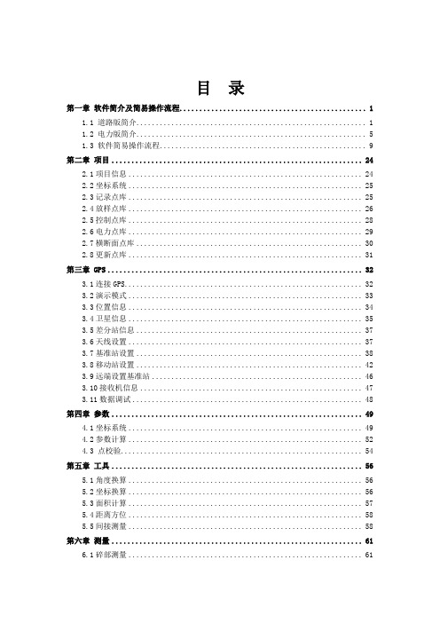
目录第一章软件简介及简易操作流程 (1)1.1 道路版简介 (1)1.2 电力版简介 (5)1.3 软件简易操作流程 (9)第二章项目 (24)2.1项目信息 (24)2.2坐标系统 (25)2.3记录点库 (25)2.4放样点库 (26)2.5控制点库 (28)2.6电力点库 (29)2.7横断面点库 (30)2.8更新点库 (31)第三章 GPS (32)3.1连接GPS (32)3.2演示模式 (33)3.3位置信息 (34)3.4卫星信息 (35)3.5差分站信息 (37)3.6天线设置 (37)3.7基准站设置 (38)3.8移动站设置 (42)3.9远端设置基准站 (46)3.10接收机信息 (47)3.11数据调试 (48)第四章参数 (49)4.1坐标系统 (49)4.2参数计算 (52)4.3 点校验 (54)第五章工具 (56)5.1角度换算 (56)5.2坐标换算 (56)5.3面积计算 (57)5.4距离方位 (58)5.5间接测量 (58)第六章测量 (61)6.1碎部测量 (61)6.2点放样 (66)6.3线放样 (68)第七章道路 (73)7.1平面设计与文件编辑 (73)7.2纵断面设计与文件编辑 (78)7.3横断面设计与文件编辑 (78)7.4道路放样 (80)7.5横断面采集 (82)第八章配置 (84)8.1软件配置 (84)8.2配色方案 (84)第九章符号释义 (87)9.1一般符号 (87)9.2按钮图形 (87)9.3当前位置信息栏 (88)9.4电量状态栏 (88)9.5卫星状态栏 (89)9.6解状态/质量栏 (89)第十章 GIS+手簿及与电脑通讯 (90)10.1 GIS+手簿 (90)10.2安装GIS+手簿连接软件 (92)10.3 GIS+手簿与电脑通讯 (96)第十一章附录 (99)11.1键盘输入 (99)11.2点信息录入 (99)11.3快捷键 (100)11.4 文件格式(道路文件) (100)11.5文件格式(点库) (102)11.6 程序结构与路径 (103)11.7 V8/v9简易硬件操作 (104)11.8 仪器常见问题及解决方法 (107)第十二章电力 (108)12.1电力作业流程简介 (108)12.2 电力勘测 (109)12.3 塔杆放样 (116)12.4 Hi-Convert数据格式转换软件 (119)第一章软件简介及简易操作流程1.1 道路版简介Hi-RTK Road软件是中海达公司最新开发出的一款基于道路施工测量的多功能手簿软件, Hi-RTK Road软件基道路工程测量行业的应用需求,广泛征集行业客户的建议,集实际工程经验和GPS作业优势于一体,是中海达测绘专业开发人员和广大客户智慧的结晶。
第四章 设置RECON手簿P(已改)

第四章设置RECON手簿§4.1 通用参数设置§4.1.1坐标系统与GPS高程模型【设置】-【坐标系统】菜单坐标系统选择您的坐标系统,如北京54、国家80等。
(用户可以使用触笔点击下拉按钮,然后选择您需要的坐标系统)如果您想自定义一个坐标系统,可以使用【添加】选项。
软件将弹出“添加坐标系”对话框添加坐标系系统名称:输入要添加的坐标系统名长半轴(米):坐标系椭球体的长半轴1/e:扁率倒数如果要删除一个坐标系统,则先用左、右键选择,再使用【删除】选项国内主要使用的坐标系统参数:1 / 19GPS(1)、正高:采用大地高程模型,接收机自动进行高程改正;(2)、椭球高:采用椭球高程模型,可以自定义高差常数。
由于大地高程模型在我国很多地区拟合程度都不是很好,所以这里建议使用椭球高,高差设置为零米。
如果需要进行高程拟合,建议在【设置】-【高程拟合】菜单中进行。
§4.1.2投影参数【设置】-【投影参数】菜单投影参数通常需要更改的只有中央子午线经度。
中央子午线经度是指测区已知点的中央子午线;若自定义坐标系,则输入该测区的平均经度。
常见几个地区的3度带中央子午线经度如下:广州:114 北京:117乌鲁木齐:84 郑州:114上海:120 成都:108§4.1.3七参数【设置】-【七参数】菜单七参数七参数是指当地坐标系统与WGS-84系统之间的转换参数。
“布尔沙”模型用在标准的坐标系求解(如BJ54,西安80等坐标系);“一步法”模型则可用在任意坐标系求解。
未知七参数时此处可以不设置,然后参考后续章节“求解七参数”。
如果当地坐标系统是WGS-84,则无法进行七参数设置。
需要注意的是比例因子△k是接近0的一个数值(如:△k=0.00005)。
§4.1.4转换参数(四参数)【设置】-【转换参数】菜单“四参数”用两个已知点的转化,可用于任何坐标系的转换。
3 / 19“网格拟合”需要选择网格拟合文件,网格拟合文件往往比较大,读取可能需要些时间,请耐心等待。
- 1、下载文档前请自行甄别文档内容的完整性,平台不提供额外的编辑、内容补充、找答案等附加服务。
- 2、"仅部分预览"的文档,不可在线预览部分如存在完整性等问题,可反馈申请退款(可完整预览的文档不适用该条件!)。
- 3、如文档侵犯您的权益,请联系客服反馈,我们会尽快为您处理(人工客服工作时间:9:00-18:30)。
第七章求解七参数与转换参数§7.1原理与意义1、坐标转换流程:求解七参数的原理:由于GPSBLH坐标(简称GPS坐标)与当地坐标之间可以通过七参数相互转换,对于一组七参数来说,每个GPS坐标就有一个唯一对应的当地坐标,我们称一个这样的坐标为一组对应关系;当我们具有一定数量的对应关系时,也可以从对应关系反求相应的七参数:i.一组对应关系可以求得七参数中的平移参数(又叫近似七参数);ii.二组对应关系可以求得两组平移参数的平均值;iii.三组对应关系恰好可以求出完整的七参数,但是无法检验结果;iv.四组以及四组以上的对应关系可以求出经过拟合的七参数,可以显示残差,通过残差即可以判断七参数的正确性并且可以对起算数据进行取舍。
2、求解四参数的原理:当已知七参数或者不使用七参数时,GPS坐标与工程坐标之间也具有相对于转换参数的对应关系;当我们具有一定数量的对应关系时,也可以从对应关系中求得相应的转换参数:i.一组对应关系可以求得转换参数中的平移参数;ii.二组对应关系恰好可以求得完整的转换参数,但是无法检验结果;iii.三组与三组以上的对应关系可以求出经过拟合的转换参数,可以显示残差,通过残差可以判断转换参数的正确性并且可以对起算数据进行取舍。
3、求解七参数和转换参数的意义:GPS是在WGS-84坐标系下工作的,而我们测量都是在施工坐标系上作业的,因此要有一组参数,将GPS测得的WGS-84坐标转换到施工坐标下。
施工中我们通常具有已知控制点的坐标(可能为当地坐标或者工程坐标),和控制点在地面上的位置,经过实地RTK测量(或者是静态GPS测量)我们即可以获得该控制点的GPS坐标,从而具有一定数量的对应关系;在获得足够的对应关系以后即可以求出相应的七参数和转换参数;获得了七参数(很多时候我们可以忽略七参数)和转换参数后,我们就可以通过RTK实时测量得到的GPS坐标获得施工需要的工程坐标,从而采集地面点的坐标(碎部测量)或者将设计的工程坐标放样到地面上。
§7.2求解七参数的操作使用菜单【辅助】-【计算七参数】,进入“求解七参数”视图:图7-1求解七参数■“新建”按钮(按“0”键):新建一个求解七参数转换文件;执行该功能,弹出“是否新建解算数据库文件”对话框,根据需要选择“YES”或“NO”●“YES”:新建解算数据库文件●“NO”:不新建解算数据库文件■“文件”按钮(按“7”键):执行该功能,则弹出下拉菜单,按相应数字键执行相应功能●提取当前记录:提取当前碎部记录文件中要参与七参数解算的点(碎部采集点和控制点坐标相关联)●提取记录点:提取碎部记录文件中要参与七参数解算的点(碎部采集点和控制点坐标相关联),弹出“选择碎部记录文件”对话框,选择碎部记录文件确定即可。
●转换文件另存为:求解七参数转换文件改名存盘●读取转换文件:打开求解七参数转换文件●添加到水准点库:将求解七参数点的高程残差作为“高程异常点”调入到水准点库中,以便求高程拟合参数■“解算”按钮(按“2”键):计算七参数■“切换”按钮(按“1”键):控制该点是否参与求参数;先选择点,再执行该功能。
如果点前打勾,则该点参与求参数;如果点前打叉,则该点不参与求参数。
★判断该点是否要参与求参数条件:1、求解七参数的点至少大于32、先使所有的点参与求七参数解算;再看各个点的残差,若残差大,则该点不参与求参数■“结果”按钮(按“6”键):弹出“七参数设置”对话框,查看求出的七参数■“应用”按钮(按“4”键):启用七参数,可以使用菜单【设置】-【七参数】,查看“七参数设置”对话框中“启用”前的方框已经打勾■“加点”按钮(按“3”键):弹出“添加计算七参数的点”的对话框,添加点图7-2添加计算点■“编辑”按钮(按“5”键):如果点的坐标有问题,选择该点,执行该功能,弹出“编辑”对话框,修改该点坐标■解算结束后,按“ESC”键退出“求解七参数”对话框,随后弹出“是否更新采集数据”对话框,若要更新,选择“YES”,若数据量很大,可以选择“NO”,在数据导出前,执行菜单【文件】-【更新数据】即可。
求解七参数可以使用两种方式:1、已知起算数据法:已知一组控制点的当地坐标和WGS-84坐标。
采用逐个“加点”的方法建立起算数据;2、后处理法:已知一组控制点的当地坐标和实际位置,但是不知道它的GPS坐标。
(1)、此时先选择当地坐标系统(例如北京54),然后关闭七参数或者将七参数全部设置为零,在一个控制点(例如A)上使用单点定位设置基准站;(2)、移动台使用同样的坐标系统和七参数设置,分别采集各个已知点(可以包括点A),采集的时候将相应的控制点与控制点的当地坐标对应起来(对应方法见步骤3),在采集各个已知点的过程之间允许对等待采集的碎部点进行采集,例如在采集B点之前对A到B之间经过的碎部点进行采集,所得到的坐标将在参数求解以后由HD-POWER自动更新;(3)、建立点的对应关系:在控制点(例如B)上记录点,在弹出的对话框中选择“控制点”选项,然后在右侧的详细中添加当地控制点(例如BDD),选择控制点类型为当地XYH或者当地BLH(必须为当地XYH或者当地BLH之一,否则在求解七参数时将无法提取到这一组对应关系),确认后输入相应的控制点坐标,再确认即可以看到相应(如下图建立B与BDD)的对应关系:图7-3添加控制点图7-4记录点属性(4)、采集结束后,在“辅助”菜单-“求解七参数”窗口中使用“文件”-“提取当前记录”,通过此方法建立一组起算数据,通过“解算”后可以得到一组“七参数”,并且可以看见在此参数下各个已知点的残差;如果您的操作获得的起算数据为空,可能是您在添加控制点时未指定类型为当地XYH和当地BLH之一,此时需要进入“控制点库”修改相应的控制点的类型为当地XYH或者当地BLH后重试“提取当前记录”,如下;图7-5控制点坐标(5)、手动筛选精度较高的已知点作为新的起算数据,然后重新“解算”;(6)、最终获得最佳“七参数”,退出求解七参数窗口并更新数据,就可以获得等待采集的碎部点经过“七参数”改正的当地坐标;(7)、求解七参数时需要注意,已知点之间距离不得过近,建议大于500米,请注意不要有重复的起算数据。
§7.3求解转换参数的操作使用菜单【辅助】-【计算转换参数】,进入“求解转换参数”视图:图7-6求解七参数图7-7添加计算点■“新建”按钮(按“0”键):新建一个求解转换参数转换文件;执行该功能,弹出“是否新建解算数据库文件”对话框,根据需要选择“YES”或“NO”●“YES”:新建解算数据库文件●“NO”:不新建解算数据库文件■“文件”按钮(按“7”键):执行该功能,则弹出下拉菜单,按相应数字键执行相应功能●提取当前记录:提取当前碎部记录文件中要参与转换参数解算的点(碎部采集点和控制点坐标相关联)●提取记录点:提取碎部记录文件中要参与转换参数解算的点(碎部采集点和控制点坐标相关联),弹出“选择碎部记录文件”对话框,选择碎部记录文件确定即可●转换文件另存为:求解转换参数转换文件改名存盘●读取转换文件:打开求解转换参数转换文件●添加到水准点库:将求解转换参数点的高程残差作为“高程异常点”调入到水准点库中,以便求高程以合参数■“解算”按钮(按“2”键):计算转换参数■“切换”按钮(按“1”键):控制该点是否参与求参数;先选择点,再执行该功能。
如果点前打勾,则该点参与求参数;如果点前打叉,则该点不参与求参数。
★判断该点是否要参与求参数条件:1、求解转换参数的点至少大于22、先使所有的点参与求转换参数解算;再看各个点的残差,若残差大,则该点不参与求参数■“结果”按钮(按“6”键):弹出“转换参数设置”对话框,查看求出的转换参数■“应用”按钮(按“4”键):启用转换参数,可以使用菜单【设置】-【转换参数】,查看“转换参数设置”对话框中“启用”前的方框已经打勾■“加点”按钮(按“3”键):弹出“添加计算转换参数的点”的对话框,添加点■“编辑”按钮(按“5”键):如果点的坐标有问题,选择该点,执行该功能,弹出“编辑”对话框,修改该点坐标■解算结束后,按“ESC”键退出“求解转换参数”对话框,随后弹出“是否更新采集数据”对话框,若要更新,选择“YES”,若数据量很大,可以选择“NO”,在数据导出前,执行菜单【文件】-【数据更新】即可。
求解转换参数也可以使用两种方式(类似求解七参数):1、已知起算数据:已知一组点的工程坐标和当地坐标。
采用逐个“加点”的方法建立起算数据;2、后处理法:已知一组点的工程坐标和实际位置,但是不知道它的当地坐标。
(1)此时先选择当地坐标系统,如果已知七参数,就设置相应当七参数;如果未知七参数,则关闭七参数或者设置为零;(2)关闭转换参数或者设置为零;在一个已知点上使用单点定位设置基准站;(3)移动台使用同样的坐标系统和七参数、转换参数设置,分别采集各个已知点,采集的时候将相应的已知点与已知的工程坐标对应起来(对应方法见步骤4),在采集各个已知点的过程之间允许对等待采集的碎部点进行采集,例如在采集B点之前对A到B之间经过的碎部点进行采集,所得到的坐标将在参数求解以后由HD-POWER自动更新;(4)建立点的对应关系:在控制点(例如B)上记录点,在弹出的对话框中选择“控制点”选项,然后在右侧的详细中添加当地控制点(例如BGC),选择控制点类型为工程XYH(必须为工程XYH,否则在求解转换参数时将无法提取到这一组对应关系),确认后输入相应的控制点坐标,再确认即可以看到相应(如下图建立B与BGC)的对应关系:图7-8添加已知点(5)采集结束后,如果开始时未知七参数,同上求解出七参数(或者关闭七参数,但是求解转换参数以后将不得对七参数进行修改,否则需要重新求解转换参数),然后更新数据;图7-9记录(6)然后在求解转换参数窗口中使用“文件”-“提取当前记录”,通过此方法建立一组起算数据;如果您的操作获得的起算数据为空,可能是您在添加控制点时未指定类型为工程XYH,此时需要进入“控制点库”修改相应的控制点的类型为工程XYH后重试;图7-10控制点(7)通过“解算”后可以得到一组“转换参数”,并且可以看见在此参数下各个已知点的残差;(8)手动筛选精度较高的已知点作为新的起算数据,然后重新“解算”;(9)最终获得最佳“转换参数”,退出求解转换参数窗口并更新数据,就可以获得等待采集的碎部点经过“转换参数”改正的工程坐标;(10)求解转换参数时需要注意,已知点之间距离不得过近,建议大于500米,请注意尤其不要有重复的起算数据;另外如果获得的比例参数小于0.97或者大于1.03,则您的起算数据很可能有错误,请检查您之前的操作。