NODEMCU-DEVKIT原理图(图片1页)
NODEMCU-DEVKIT中文
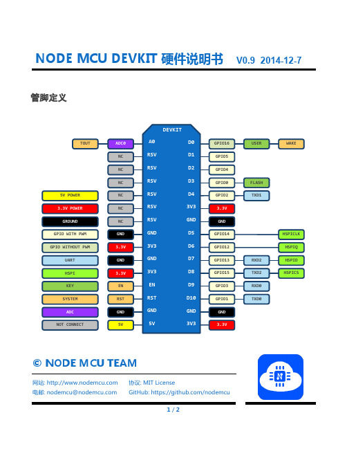
© NODE MCU TEAM网站: 电邮: nodemcu@协议: MIT LicenseGitHub: https:///nodemcu1 / 2NODE MCU DEVKIT 硬件说明书V0.9 2014-12-7管脚定义GPIO16 GPIO5 GPIO4 GPIO0 GPIO2 GND 3V3EN RST GND 5VD0 D1 D2 D3 D4 3V3 GND D5 D6 D7 D8D9 D10 GND 3V3A0 RSV RSV RSV RSV RSV RSV GND 3V3 3.3V GND GPIO14 GPIO12 GPIO13 GPIO15GPIO3 GPIO1 GND 3.3VADC0 NC NC NCNC NC NC GND 3.3V GND 3.3VEN RST GND 5VUSER FLASH TXD1RXD2 TXD2RXD0 TXD0WAKEHSPICLK HSPIQHSPID HSPICSTOUT3.3V POWER 5V POWER GROUND GPIO WITH PWM GPIO WITHOUT PWMUART HSPIKEY SYSTEM ADC NOT CONNECTDEVKITNODE MCU DEVKIT 硬件说明书注意事项1. 连接开发板硬件之前,确保断开所有电源以避免触电危险。
开发板上包含尖锐物体,使用时应当十分小心以避免意外伤害。
禁止用手指直接触摸开发板裸露金属部分,防止意外扎伤手指。
另外直接触摸金属部分可能导致静电损坏开发板。
未成年人需要在成年人监护下使用此开发板。
2. 开发板天线附近请保持足够的净空区,否则会影响天线性能。
3. 开发板的USB接口与计算机连接时,如果开发板的串口没有被打开,插拔计算机USB外设的操作会造成开发板复位。
只有使用计算机供电且串口未被打开时会发生此问题,如果使用普通USB电源供电或计算机已经打开串口则不会发生此问题。
安信可-NodeMCU-8266 规格书-中文说明书

NodeMCU-8266规格书版本V1.2版权©2020免责申明和版权公告本文中的信息,包括供参考的URL地址,如有变更,恕不另行通知。
文档“按现状”提供,不负任何担保责任,包括对适销性、适用于特定用途或非侵权性的任何担保,和任何提案、规格或样品在他处提到的任何担保。
本文档不负任何责任,包括使用本文档内信息产生的侵犯任何专利权行为的责任。
本文档在此未以禁止反言或其他方式授予任何知识产权使用许可,不管是明示许可还是暗示许可。
文中所得测试数据均为安信可实验室测试所得,实际结果可能略有差异。
Wi-Fi联盟成员标志归Wi-Fi联盟所有。
文中提到的所有商标名称、商标和注册商标均属其各自所有者的财产,特此声明。
最终解释权归深圳市安信可科技有限公司所有。
注意由于产品版本升级或其他原因,本手册内容有可能变更。
深圳市安信可科技有限公司保留在没有任何通知或者提示的情况下对本手册的内容进行修改的权利。
本手册仅作为使用指导,深圳市安信可科技有限公司尽全力在本手册中提供准确的信息,但是深圳市安信可科技有限公司并不确保手册内容完全没有错误,本手册中的所有陈述、信息和建议也不构成任何明示或暗示的担保。
文件制定/修订/废止履历表版本日期制定/修订内容制定核准V1.02016.10.04首次制定杨小飞V1.12019.03.04资料更改谢一骥V1.22020.04.23资料更改谢一骥目录一、产品概述 (5)二、电气参数 (7)三、外观尺寸 (8)四、管脚定义 (9)五、原理图 (11)六、设计指导 (11)七、回流焊曲线图 (12)八、包装信息 (13)九、联系我们 (13)一、产品概述NodeMCU-8266开发板是安信可针对ESP8266模组而设计的一款核心开发板,该开发板延续了NodeMCU1.0经典设计,引出全部I/O至两侧的排针,开发者可以根据自己的需求连接外设。
使用面包板进行开发和调试时,两侧的标准排针可以使操作更加简单方便。
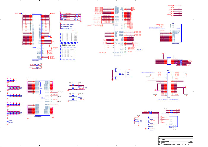
诺基亚6170 7270 CPU与存储器电路图

/MMC_reg_on
BT PCM Clk BT PCM out BT PCM in BT PCM sync
J2810
A
5 4 3 2
J2811 J2812 J2813 J2814 29 30 31
G2 K8 H4 H3 K7 J2 J4 C1 E4 D2 F4 E3 T3 P8 U1 U2 W1 T4 V3 W2 U3 U4 V4 W3 W9 Y4 Y1
1 2 3 4 5 6 7 8 9 10 11 12 13 14 15 16 18 19 20 21 22 23 24 25 26 27 28
R3700 1k0
R3700
Pull up to ’1’
Not assy Not assy Assy Assy
Assy
Not assy Assy
GENIO(31:0)
KEYB(10:0)
UI
0 TXD SD
N2600 CIM-50M5A-T 2 LEDC LEDA 1 3 Txd Rxd 4
5 SD VLOGIC 7 6 Vcc GND 8 GND 9
14 15 16 17 18 19 20 21 22 23 24 25 26 27 28 29
C2601 27p
IrDa Rx IrDa Tx keyboard keyboard keyboard keyboard keyboard keyboard keyboard keyboard keyboard keyboard keyboard keyboard keyboard MMC Clk MMC Data MMC Cmd MMC Data Dir MMC Cmd Dir (Ext USBClk Enable) LCDTear
基于NodeMCU的双向通信系统
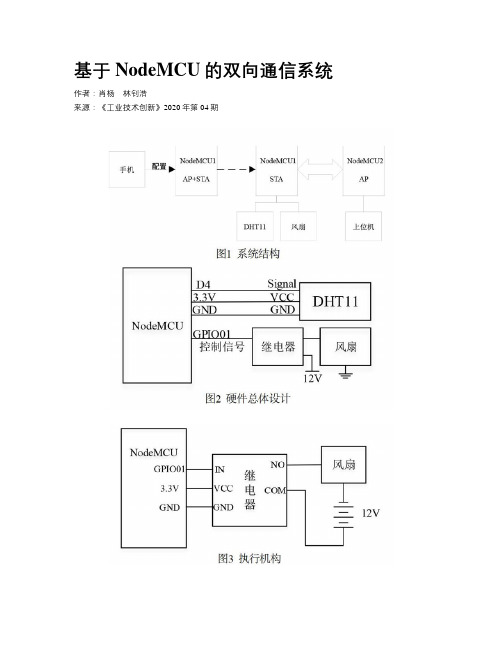
基于NodeMCU的双向通信系统作者:肖杨林钊浩来源:《工业技术创新》2020年第04期摘 ; 要: Wi-Fi是广泛应用于物联网的无线通信技术,但具有传输功耗过高的缺陷,故提出一种基于NodeMCU的双向通信系统。
在硬件上,NodeMCU搭载ESP8266-F12模块实现无线通信,可有效降低传输功耗;在软件上,NodeMCU模块灵活实现接入点(AP)、控制端(STA)及混合模式(AP+STA)配置,用户通过连接配置界面,可实现数据传输与设备控制需求;系统采用轻量化的JSON数据传输格式,具有方便、稳定的数据传输通道,有效实现了物联网系统云边端架构中的边—端环节,可方便地搭接到云平台,构成通信高效、功耗较低的物联网系统。
关键词: NodeMCU;ESP8266-F12;Wi-Fi;无线通信;双向通信;物联网中图分类号:TP273 ; ;文献标识码:A ; ;文章编号:2095-8412 (2020) 04-080-05工业技术创新 URL: http:// ; ;DOI: 10.14103/j.issn.2095-8412.2020.04.015引言随着无线通信技术多样化、快速发展,人们对远程控制产品的多样化需求也不断增加,针对智能家居等基于无线通信、远程遥控的技术层出不穷。
其中,短距离无线传输技术以其低能耗、低成本、能够适应复杂环境的优点,在无线通信领域起着至关重要的作用[1]。
Wi-Fi、蓝牙、ZigBee等短距离无线通信技术都应用广泛,且各有所长,在不同的应用场景中发挥着作用和优势。
其中Wi-Fi传输在当下应用较广泛,但是其传输功耗问题一直受到诟病,而NodeMCU能够在满足物联网设备相关功能的同时降低Wi-Fi传输功耗,从而有效改善这一缺陷[2]。
现在比较常见的NodeMCU应用方法是将其移植到专用的机智云SOC方案中,但这种做法并不能很好地将NodeMCU嵌入到物联网系统云边端架构中。
EM3 V2.2开发板原理图(修正版)
J12 8 7 6 5 4 3 2 1 JR1 JR2 JR3 JR4 JR5 JR6 JR7 JR8 GND LE 2 3 4 5 6 7 8 9 1 11
P10
LED1 b c dp f e
LED2 b c dp GND 1 2 3 4
CX8
VCC
J1602
COM a GND JR8 JR7 JR6 JR5 5 6 7 8 RP22 103 4 3 2 1 GND Q0 Q1 Q2 Q3 Q4 Q5 Q6 Q7 19 18 17 16 15 14 13 12 20 10 4 3 2 1 4 3 2 1 VCC GND RP20 101 5 6 7 8 5 6 7 8 f e g b f c dp e
DS1302
32.768 A1 VCC U0 1 VCC2 VCC1 2 X1 SCLK 3 X2 I/O 4 GND CE DS1302
GND 74HC595 U5 OE RCLK SRCLR SRCLK SER
P36 VCC QA QB QC QD QE QF QG QH QH' 16 15 1 2 3 4 5 6 7 9 P16 VCC P595_B 1 2 3 4 5 6 7 8
c e
NTC1 AD1 502 1 2 AIN1 R68 103 R69 104
GR1 1 2 AIN2 1 DI 2 T-CS 3 CLK 4
VCC R1 4.7K
U3 ET2046 12 11 10 9 AIN3 AIN2 GND
GND
C
VCC X+ Y+ X-
R2 16K R0 GND 330R +5V RQ0 B
9
VCC a f e g d b c dp
Handson Technology ESP8266 NodeMCU WiFi开发板用户手册说明书
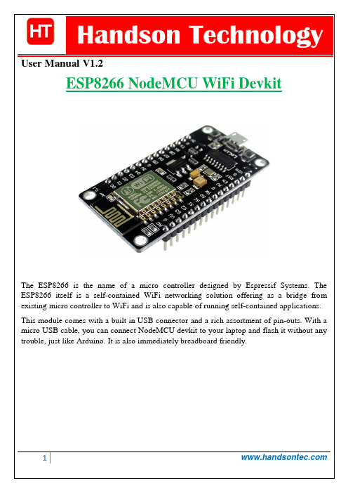
User Manual V1.2The ESP8266 is the name of a micro controller designed by Espressif Systems. The ESP8266 itself is a self-contained WiFi networking solution offering as a bridge from existing micro controller to WiFi and is also capable of running self-contained applications. This module comes with a built in USB connector and a rich assortment of pin-outs. With a micro USB cable, you can connect NodeMCU devkit to your laptop and flash it without any trouble, just like Arduino. It is also immediately breadboard friendly.Table of Contents1. Specification: (3)2. Pin Definition: (3)3. Using Arduino IDE (3)3.1 Install the Arduino IDE 1.6.4 or greater (4)3.2 Install the ESP8266 Board Package (4)3.3 Setup ESP8266 Support (5)3.4 Blink Test (7)3.5 Connecting via WiFi (9)4. Flashing NodeMCU Firmware on the ESP8266 using Windows (12)4.1 Parts Required: (12)4.2 Pin Assignment: (12)4.3 Wiring: (13)4.4 Downloading NodeMCU Flasher for Windows (13)4.5 Flashing your ESP8266 using Windows (13)5. Getting Started with the ESPlorer IDE (15)5.1 Installing ESPlorer (15)5.2 Schematics (18)5.3 Writing Your Lua Script (18)6. NodeMCU GPIO for Lua (22)7. Web Resources: (22)ing Arduino IDEClick ‘File’ -> ‘Preferences’ to access this panel. Next, use the Board manager to install the ESP8266 package.Click ‘Tools’ -> ‘Board:’ -> ‘Board Manager…’ to access this panel.Scroll down to ‘ esp8266 by ESP8266 Community ’ and click “Install” button to install the ESP8266 library package. Once installation completed, close and re-open Arduino IDE for ESP8266 library to take effect.Setup ESP8266 SupportWhen you've restarted Arduino IDE, select ‘Generic ESP8266 Module’ from the ‘Tools’ -> ‘Board:’ dropdown menu. Select 80 MHz as the CPU frequency (you can try 160 MHz overclock later)Find out which Com Port is assign for CH340 Select the correct Com Port as indicated on ‘Device Manager” Note: if this is your first time using CH340 “ USB-to-Serial ” interface, please install the driver first before proceed the above Com Port setting. The CH340 driver can be download from the below site:Once the ESP board is in bootload mode, upload the sketch via the IDE, Figure 3-2.Figure3-1: Connection diagram for the blinking testFigure 3.2: Uploading the sketch to ESP8266 NodeMCU module.The sketch will start immediately - you'll see the LED blinking. Hooray!Connecting via WiFiOK once you've got the LED blinking, let’s go straight to the fun part, connecting to a webserver. Create a new sketchconst char* host ="";void setup(){Serial.begin(115200);delay(100);// We start by connecting to a WiFi networkSerial.println();Serial.println();Serial.print("Connecting to ");Serial.println(ssid);WiFi.begin(ssid, password);while(WiFi.status()!= WL_CONNECTED){delay(500);Serial.print(".");}Serial.println("");Serial.println("WiFi connected");Serial.println("IP address: ");Serial.println(WiFi.localIP());}int value =0;void loop(){delay(5000);++value;Serial.print("connecting to ");Serial.println(host);// Use WiFiClient class to create TCP connectionsWiFiClient client;const int httpPort =80;if(!client.connect(host, httpPort)){Serial.println("connection failed");return;}// We now create a URI for the requestString url ="/projects/index.html";Serial.print("Requesting URL: ");Serial.println(url);// This will send the request to the serverclient.print(String("GET ")+ url +" HTTP/1.1\r\n"+"Host: "+ host +"\r\n"+"Connection: close\r\n\r\n");delay(500);// Read all the lines of the reply from server and print them to Serial while(client.available()){String line = client.readStringUntil('\r');Serial.print(line);}Serial.println();Serial.println("closing connection");}That's it, pretty easy right ! This section is just to get you started and test out your module.ESP8266 Module Breadboard Friendly with Header ConnectorESP8266 Module Breadboard FriendlyPL2303HX USB-UART Converter CableSome Male-to-Female Jumper WiresESP8266 Pin DescriptionCH_PD Pull high, connect to Vcc +3.3VVcc Power Supply +3.3VTXD Connect to RXD (white) of PL2303HX USB-Serial converter cable RXD Connect to TXD (Green) of PL2303HX USB-Serial converter cable GPIO0 Pull low, connect to GND pinGND Power Supply groundPress the button “Flash” and it should start the flashing process immediately, showing the Module MAC address if After finishing this flashing process, it should appear a green circle with a check icon at lower left corner.Your ESP8266 module is now loaded with NodeMCU firmware.Here’s a rundown of the features the ESPlorer IDE includes:Syntax highlighting LUA and Python code.Code editor color themes: default, dark, Eclipse, IDEA, Visual Studio.Undo/Redo editors features.Code Autocomplete (Ctrl+Space).Below the Code Window, you have 12 buttons that offer you all the functions you could possible need to interact with your ESP8266. Here’s the ones you’ll use most: “Save to ESP” and “Send to ESP”.5.3 Writing Your Lua ScriptBelow is your script to blink an LED.lighton=0pin=4gpio.mode(pin,gpio.OUTPUT)Right now you don’t need to worry how this code works, but how you can upload it to your ESP8266.Look at the top right corner of your ESPlorer IDE and follow these instructions: Press the Refresh button.Select the COM port for your FTDI programmer.Select your baudrate.Click Open.Copy your Lua script to the code window (as you can see in the Figure below):Congratulations, you’ve made it! The blue LED at the upper right corner should be blinking every 2 seconds!6. NodeMCU GPIO for LuaThe GPIO(General Purpose Input/Output) allows us to access to pins of ESP8266 , all the pins of ESP8266 accessed using the command GPIO, all the access is based on the I/O index number on the NoddMCU dev kits, not the internal GPIO pin, for example, the pin ‘D7’ on the NodeMCU dev kit is mapped to the internal GPIO pin 13, if you want to turn ‘High’ or ‘Low’ that particular pin you need to called the pin number ‘7’, not the internal GPIO of the pin. When you are programming with generic ESP8266 this confusion will arise which pin needs to be called during programming, if you are using NodeMCU devkit, it has come prepared for working with Lua interpreter which can easily program by looking the pin names associated on the Lua board. If you are using generic ESP8266 device or any other vendor boards please refer to the table below to know which IO index is associated to the internal GPIO of ESP8266.Nodemcu dev kit ESP8266 Pin Nodemcu devkitESP8266 PinD0 GPIO16 D7 GPIO13D1 GPIO5 D8 GPIO15D2 GPIO4 D9 GPIO3D3 GPIO0 D10 GPIO1D4 GPIO2 D11 GPIO9D5 GPIO14 D12 GPIO10D6 GPIO12D0 or GPIO16 can be used only as a read and write pin, no other options like PWM/I2C are supported by this pin.In our example in chapter 5 on blinking the blue LED, the blue LED in connected to GPIO2, it is defined as Pin4 (D4) in Lua script.7. Web Resources:•ESP8266 Lua Nodemcu WIFI Module•ESP8266 Breadboard Friendly Module•ESP8266 Remote Serial WIFI Module•PL2303HX USB-UART Converter Cable。
龙芯开发板DEV_3210原理图
C
XP3 INT3 CAN1_RX CAN1_TX CAN0_RX LCD_EN/CAN0_TX 1 3 5 7 9 11 6x2/SM 2 4 6 8 10 12 INT2 I2C_DATA 2 R137 I2C_CLK 2 R138 R144 2 R146 2 R145 2 R147 2
3.3V NN_RDY R45 10K 3.3V CKE# R133 10K C111 XTLI
3.3V
60OHM/100MHz-1.5A FB22 60OHM/100MHz-1.5A 1.8V-PLL_5AP 1.8V FB21 1.8V-PLL_5AP VCC_LCD C96 0.1uF AGND_5AP
1
C106 C93 C100 C107 C90 0.1uF 0.1uF 0.1uF 0.1uF 0.1uF
AC97_DIN AC97_DOUT AC97_SYNC AC97_RST AC97_BITCLK VINETIC_RST# VINETIC_CS# VINETIC_RDY# I2C_DATA I2C_CLK
EMI_OE_ NR_CS_ SDCLK GC3210I-QFP208
A18 下拉 下拉 下拉 下拉 上拉 上拉 上拉 上拉
EMI_OE 下拉 上拉 下拉 上拉 下拉 上拉 下拉 上拉
CPU时钟 不用 150MHz 160MHz 175MHz 200MHz 225MHz 250MHz 266MHz
TAP_SEL TRST_N TMS TDI TDO TCK
51 45 49 48 47 50 203 202 41 37
UART_TXD0 UART_RXD0 UART_TXD1 UART_RXD1 SPI_SS SPI_MISO SPI_MOSI SPI_SCLK