LED同步控制系统MCTRL300产品说明书
M3系统快速入门手册
图 4-1 显示屏配置
提示:
如果图 4-1中的发送卡分辨率与显卡输出分辨率不一致,那么请参照9.分辨率与刷新 率调整来修改发送卡的分辨率或者是在电脑上修改显卡输出的分辨率,否则在智能设
置过程,显示屏可能显示不正确。
步骤 2: 在图 4-1 中切换到接收卡页面,点击接收卡页面下方的“智能设置”按钮,弹出智能设
2
西安诺瓦电子科技有限公司
M3 系统快速入门手册
1. M3 系统连接方案
图 1-1 M3 系统连接方案
2. M3 系统带载能力说明
MSD300(发送卡):1280×1024、1024×1200、1600×848、1920×712、2048×668; MSD600(发送卡): 8Bit : 1920x1080, 2048x960, 2560x960; 12/10Bit: 1440x900, 960x1080; MCTRL300(控制器):1280×1024、1024×1200、1600×848、1920×712、2048×668; MCTRL500(控制器):1920×1200、2048×1152 ; MRV300/320(接收卡):256×128,200×200。
章节标识符定义
★
重点章节(常用操作)
*
特殊章节(特定条件下的操作)
1
目录
目录
M3 系统快速入门手册 ...................................................................................................................3 1. M3 系统连接方案 ....................................................................................................................3 2. M3 系统带载能力说明 ............................................................................................................3 3. 使用接收卡配置文件点亮显示屏★.......................................................................................3 4. 通过手动配置点亮显示屏.......................................................................................................5
诺瓦科技LED显示屏发送卡MCTRL300产品说明书
MCTRL300独立主控卡产品说明书产品版本:V1.0.0文档编号:NS110000346版权所有© 西安诺瓦电子科技有限公司2017。
保留一切权利。
非经本公司书面许可,任何单位和个人不得擅自摘抄、复制本文档内容的部分或全部,并不得以任何形式传播。
商标声明声明欢迎您选用西安诺瓦电子科技有限公司(以下简称诺瓦科技)的产品,如果本文档为您了解和使用产品带来帮助和便利,我们深感欣慰。
我们在编写文档时力求精确可靠,随时可能对内容进行修改或变更,恕不另行通知。
如果您在使用中遇到任何问题,或者有好的建议,请按照文档提供的联系方式联系我们。
对您在使用中遇到的问题,我们会尽力给予支持,对您提出的建议,我们衷心感谢并会尽快评估采纳。
www.novastar-l i更新记录MCTRL300 独立主控卡产品说明书更新记录产品说明书目录目录更新记录 (ii)目录 (iii)1概述 (1)2接口示意图 (2)3操作说明 (3)3.1硬件连接 (3)3.2软件操作 (3)3.2.1显示屏配置 (3)3.2.2发送卡分辨率及刷新率的调整 (7)3.2.3冗余设置 (8)产品说明书1概述1概述诺瓦M3系列独立主控卡MCTRL300支持视频、音频输入,经过解码、数据处理之后将视频和音频从网口发送给显示屏,单卡支持分辨率最高可达2048×668,通过USB接口与计算机通信,使用方便。
功能特点●DVI视频输入。
●USB接口控制,可级联多台设备进行统一控制。
●支持音频输入。
●双网口输出。
●单卡支持分辨率有1280×1024,1024×1200,1600×848,1920×712,2048×668。
●一路光探测头接口。
产品说明书2接口示意图2接口示意图图2-1MCTRL300接口示意图3操作说明独立主控MCTRL300的管理包括:对多功能卡的配置(如:添加,删除、重命名)、外设配置、刷新多功能卡监控数据、电源管理。
DMX300_DMX控制器中文说明书.pdf

DMX512 控制器DMX300LED 全彩控制器DMX300产品概述产品特点符合DMX512(1990)国际标准协议数码显示屏直观显示当前状态无线遥控控制及按键控制,友好的人机界面控制系统实现R,G,B各256级灰度,共可表现1677万种颜色,真正实现真彩色内置多种变化模式,变化暂停功能8级速度调节参数自动记忆可通过配套软件方便地进行变化效果的即时更新支持多种输出接口:XLR-3公母,RJ45布线及灯具安装简单方便具有良好的抗干扰功能,并且具有故障自动恢复功能DMX 300 LED全彩控制系统是一套用于建筑室内外亮化控制的LED全彩控制系统,它集LED灯光效果编辑软件和控制器为一体,设计师可方便的随时修改控制器中的灯光效果。
控制系统实现R,G,B各256级灰度,共可表现1677万种颜色,真正实现全彩色。
独有的无线遥控和按键控制变化方式和速度调节功能;多达30种变化模式和8级速度调节;支持变化暂停功能,可方便的保持特定的颜色。
输入电压:12VDC(配AC220/110V转12V适配器)消耗功率:< 5W存储量:64KB输出回路: 1 port传输信号:DMX512(1990)传输速率:250Kbps可控灯具数:默认50像素,最大170像素可控灯具类型:投射灯,轮廓灯,灯砖,地埋灯水下灯等等控制方式:异步全彩变化控制遥控性能:50米描述:内置跳变,渐变,流水,追逐等30种效果尺寸:190(mm)*123(mm)*53(mm)毛重: 1 KG净重:0.8 KG产品尺寸图:DMX512 控制器DMX300 DMX300 面板装置①数码管显示屏(前两位表示模式,第四位表示速度)②MODE:按下该键,切换变化模式③PAUSE:按下该键,使LED保持当前颜色;④SPEED+:按下该键,使LED变化速度增加一级⑤SPEED-:按下该键,使LED变化速度减小一级注:当按下②MODE键时,数码管显示屏中用于显示当前所处模式位置(本控制器共30种模式)的前两位数码管所显示数字会顺序变化;当按下③PAUSE键时,数码管显示屏中第一位数码管会显示字母P用于表示暂停,当再次按下该键时,则显示屏又恢复显示当前模式值和速度值;当按下④SPEED+时,数码管显示屏中的第四位数码管中所显示数字会依次递减(最大数字为8,最小为1,值越大速度越慢反之速度越快);当按下⑤SPEED-时,数码管显示屏中的第四位数码管中所显示数字会依次递增(最大数字为8,最小为1,值越大速度越慢反之速度越快)DMX300后板装置①电源开关②电源输入口③USB下载接口④RJ45输出口⑤XLR 3公头输出端口⑥XLR 3母头输出端口DMX512 控制器DMX300DMX300输出端口说明1. RJ45输出端口1: DATA+2: DATA-3-6: NC7-8: GND2. XLR 3 输出端口1: GND2: DATA-3: DATA+遥控器说明 按键功能:A: Mode; B: Pause;C: Speed+; D: Speed-.Mode : 按下该键,切换变化模式;Pause :按下该键,使LED 保持当前颜色;再次按下,则继续变化;Speed+:按下该键,使LED 变化速度增加一级(默认为最快级别);Speed-:按下该键,使LED 变化速度减小一级。
LED全彩联机控制系统使用说明书
LED全彩联机控制系统使用说明书(适用:PC-9)江门市思域科技有限公司2011-10-01目录第1章概述 (3)1.1 主控型号类型 (3)1.2 控制系统适用方案选择指引 (3)1.3 控制器容量 (3)1.4 分控容量 (4)第2章编辑软件说明 (5)2.1使用环境 (5)2.2软件所需文件列表 (6)2.3调试目的 (7)2.4调试前的准备 (7)2.5调用播放器内部的测试文件(选做) (10)2.5.1播放器自动生成6种测试效果 (10)2.6带音控的电脑屏,音控部分的设置。
(11)第3章编播软件的使用 (16)3.1编播软件主要特点 (16)3.2界面说明 (16)3.3软件使用说明 (17)3.3.1实时播放 (17)3.3.2动画播放 (18)3.3.3 Win 7下的实时播放 (19)3.3.4录像播放 (20)3.3.5文字显示 (22)3.3.6录制功能(录像开始及录像结束) (25)3.4其它功能按钮使用说明 (26)3.4.1色彩调整 (26)3.4.2内置效果 (27)3.4.3安装设置 (37)第4章播放软件修改参数 (39)4.1第一步:软件设置: (39)4.1.1信号线走线方式选择: (39)4.1.2屏体尺寸及显示比例 (41)4.2第二步:灯板设置: (43)4.2.1第一类:思域特有的灯板 (44)4.2.2第二类:市场上比较通用的灯板 (44)4.2.3 第三类:客户自定义脚位的灯具 (46)4.3第三步:硬件设置: (46)4.4参数固化 (47)第1章概述1.1主控型号类型在订购控制器前,首先要了解本公司可提供客户的控制器类型及其相关性能。
本公司控制器有以下几种型号:控的型号及数量。
第2章编辑软件说明2.1使用环境1)系统环境须为Windows XP或Windows 7(win 7需使用基本主题和管理员权限)。
2)软件版本语言字符须与系统语言环境一致。
LED同步控制系统MCTRL R5用户手册
5.6.4 固化至接收卡 ......................................................................................................................................... 12 5.6.5 冗余设置................................................................................................................................................. 12 5.6.6 预设模板................................................................................................................................................. 12 5.6.7 输入源热备份 ......................................................................................................................................... 12 5.6.8 工厂复位................................................................................................................................................. 12 5.6.9 返回主界面时长(s)............................................................................................................................. 12 5.6.10 灰度调节............................................................................................................................................... 12 5.6.11 硬件版本 ............................................................................................................................................... 12
LED同步控制系统MCTRL4K规格书英文版
Independent Controller
XI'AN
NOVASTAR TECH CO.,LTD. Specifications
Product Version: V1.0.3 Document Number: NS110100428
Copyright © 2018 Xi’an NovaStar Tech Co., Ltd. All Rights Reserved.
XI'AN
www.novastar.tech
iii
Independent Controller MCTRL4K Specifications
1 Safety
1 Safety
D. This chapter illustrates safety of the MCTRL4K independent controller to ensure the T product’s storage, transport, installation and use safety. .,L Safety instructions are applicable to all personnel who contact or use the product. O First of all, pay attention to following points. C Read through the instructions.
Trademark
is a trademark of Xi’an NovaStar Tech Co., Ltd.
Statement
. You are welcome to use the product of Xi’an NovaStar Tech Co., Ltd. (hereinafter referred to as D NovaStar). This document is intended to help you understand and use the product. For accuracy and T reliability, NovaStar may make improvements and/or changes to this document at any time and .,L without notice. Any problem in use or any good suggestion, please contact us through ways provided
诺瓦科技LED控制卡MCTRL600规格书

诺瓦科技LED控制卡MCTRL600规格书Independent Controller MCTRL600V2.1.0 NS110100121OverviewMCTRL600 is an advanced model of Nova controllers, which supportsextra-large resolution. With HDMI/DVI video input and four Ethernetport outputs, a single unit is able to load 2560×960. Multiple units canAppearancebe cascaded for uniform control.Feature1) HDMI/DVI input;2) HDMI/external audio input;3) 12 b it/10bit/8bit HD video source;4) Resolution supported: 2048 ×1152 ,1920 ×1200 ,2560 ×960 ;5) Resolution supported: 1440 ×900 (12 b it/10bit);6) light sensor interface;17) Cascading supported;8) 18 b it gray scale processing and presentation;9) Video format: RGB, YCrCb4:2:2, YCrCb4:4:4;10) Standard 1U housing and independent power supply.Dimensions19" 1U Standard Cabinet.Unit: mmSpecificationsXi’an Co.,FCC CautionAny Changes or modifications not expressly approved by the partyresponsible for compliance could void the user's authority tothe equipment.This device complies with part 15 of the FCC Rules. Operation is subjectto the following two conditions: (1) This device may not cause harmfulinterference, and (2) this device must accept any interference received,including interference that may cause undesired operation. Note: Thisequipment has been tested and found to comply with the limits for aClass B digital device, pursuant to part 15 of the FCC Rules. These limitsare designed to provide reasonable protection against harmfulinterference in a residential installation. This equipment generates, usesand can radiate radio frequency energy and, if not installed and used inaccordance with the instructions, may cause harmful interference toradio communications. However, there is no guarantee that interference will not occur in a particular installation. If this equipmentdoes cause harmful interference to radio or television reception, whichcan be determined by turning the equipment off and on, the user isencouraged to try to correct the interference by one or morefollowing measures:—Reorient or relocate the receiving antenna.—Increase the separation between the equipment and receiver. —Connect the equipment into an outlet on a circuit different from that towhich the receiver is connected.—Consult the dealer or an experienced radio/TV technician for help.This equipment complies with FCC radiation exposure limits set forthfor an uncontrolled environment .This equipment should be installedand operated with minimum distance 20cm between the radiator &your body.This transmitter must not be co-located or operating in conjunctionwith any other antenna or transmitter.。
300W LED 灯条使用说明书
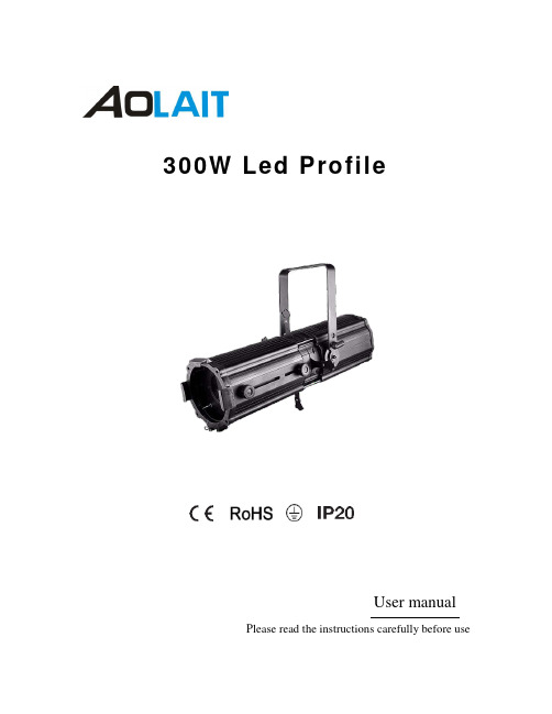
300W Led ProfileUser manualPlease read the instructions carefully before use1.Safety InformationBe careful with your operations. With a dangerous voltage you cansuffer a dangerous electric shock when touching wires!This device has left the factory in perfect condition. In order to maintain this condition and to ensure a safe operation, it is absolutely necessary for the user to follow the safety instructions and warning notes written in this user manual.Damages caused by the disregard of this user manual are not subject towarranty. The dealer will not accept liability for any resulting defects orproblems.If the device has been exposed to temperature changes due to environmental changes, do not switch it on immediately. The arising condensation could damage the device. Leave the device switched off until it has reached room temperature.This device falls under protection-class I. Therefore it is essential that the device be earthed.The electric connection must carry out by qualified person. The device shall only be used with rate voltage and frequency.Make sure that the available voltage is not higher than stated at the end of this manual. Make sure the power cord is never crimped or damaged by sharp edges. If this would be the case, replacement of the cable must be done by an authorized dealer.Always disconnect from the mains, when the device is not in use or before cleaning it. Only handle the power cord by the plug. Never pull out the plug by tugging the power cord.During initial start-up some smoke or smell may arise. This is a normal process and does not necessarily mean that the device is defective, it should decrease gradually.Please don't project the beam onto combustible substances.Fixtures cannot be installed on combustible substances, keep more than 50cm distance with wall for smooth air flow, so there should be no shelter for fans and ventilation for heat radiation.If the external flexible cable or cord of this luminaire is damaged, it shall be exclusively replaced by the manufacturer or his service agent or a similar qualified person in order to avoid a hazard.2.UnpackingThank you for choosing our AL300LP. For your own safety, please read this manual before installing the device. This manual covers the important information on installation and applications. Please install and operate the fixture with following instructions. Meanwhile, please keep this manual well for future needs.The AL300LP is made of a new type of high temperature strength of cast aluminum casing with nice outlook. The fixture is designed and manufactured strictly following CE standards, complying with international standard DMX512 protocol. It's available independently controlled and linkable with each other for operation. And it is applicable for large-scale live performances, theater, studio, nightclubs and discos.The AL300LP adopts 1PCS NICHIA 300W (available for WW) which features high brightness and stability. Please carefully unpack it when you receive the fixture and check whether it is damaged during the transportation. And please check whether the following items are included inside the box: ①②④①AL300LP 1PC②Signal Cable1PC③Power Cable1PC④User Manual1PC③3. Features & SpecificationsVoltage: AC100-240V 50/60HZ Power: 350WLight Source: NICHIA 300W Lifespan: 50000 HoursColor Temperature: 3200K/5600K Color Rendering Index (CRI): Ra≥95 Zoom angle: 12°-36 °Dimming: 16bit linear dimming, four dimming curve selection Control mode: Standard DMX 512/master-slave/auto DMX Channels: 1/3 Channels Body color: Black Shell: Cast aluminumCooling System: Powerful fan IP Grade: IP20SpecificationsVoltage:AC10-240V 50/60HzDimensions: 195(D)*720(W)*415(H)mm Packing size: 332(D)*832(W)*345(H)mm Net Weight: 10.2kg Gross Weight: 12.2kg7201951954154. DMX512 Control ConnectionsConnect the provided XLR cable to the female 3-pin XLR output of your controller and the other side to the male 3-pin XLR input of the moving head. You can chain multipleMoving head together through serial linking. The cable needed should be two core, screened cable with XLR input and output connectors. Please refer to the diagram below. DMX-512 connection with DMX terminatorDigital DISPLAY5-Pin DMX OUTPOWER OUT ENTER Ground3-Pin DMX IN MENU Power Switch3-Pin DMX OUTUPPOWER IN POWER IN5-Pin DMX IN DOWNFUSE 5-Pin DMX IN 3-Pin DMX IN5.Menu OperationsDMX Output3-Pin XLR SocketDMX Input3-Pin XLR Socket1:Ground2:Data(-)3:Data(+)COMMONDMX+DMX-DMX 512 OUT3-PIN XRLDMX 512 IN3-PIN XRL 120ΩPin2Pin3For installations where the DMX cable has to run a longdistance or is in an electrically noisy environment, such as ina discotheque, it is recommended to use a DMX terminator.This helps in preventing corruption of the digital controlsignal by electrical noise. The DMX terminator is simply anXLR plug with a 120 Ωresistor connected between pins 2and 3,which is then plugged into the output XLR socket of thelast fixture in the chain. Please see illustrations below.5.1. Key operationMenu:The first list is the main menu (press MENU toexchange), the second list is submenu (press ENTER toget in or exchange)If the menu include the decimal point, that’s the data,and it can be set by the Key of Up/Down.Key operation:Key of “MENU” (Press it and can save the data)If it’s the main menu, it will exchange to next mainmenu.If it’s the submenu, it will back to main menu.Key of “ENTER” (Press it and can save the data)If it’s the main menu and it have submenu, it will enterthe submenu.If it’s the submenu, it will exchange to the nextsubmenuKey of “UP/DOWN”It’s no function if the menu not include the decimalpoint.If the menu include the decimal point, it can set the dataafter the decimal point. And it need to press “ENTER” tosave the data.5.2.Menu DataMenuStateOperationRemarkMain MenuVice MenuNo vice menuA: advance UP/DOWN adjust ID adress disconnect thecontroller and connect the master light, then it will follow the master light. It will flicker if nosignal. External control mode (standard channel model) ENTER save the IDaddressNo vice menud: dmx UP/DOWN adjust IDaddressExternal control mode (Basic channel model) ENTER Save the ID addresstwo vice menuStAt: static ENTER enter vice menu Static modelC: Color UP/DOWN change value of colorSet the colorENTERsave the data change to the vice menuSt: strobeUP/DOWN change value of strobe strobe and its speedENTER save and exchangetwo vice menu tEMp: temperature ENTER enter the vice menu temperature controlcurrent temperature ENTER change to vice menut: topUP/DOWNchange the data of temperature protectset the protect temperature ENTER save and changeNo vice menudiSP: display ENTER reverse the displayset to show reverse displayNo vice menurESt: reset ENTER enter the interface of key the password is “UP DONW UP DOWN” return Initial State6. DMX Channels3 CH Mode1 CH ModeChannelFunction Value Description 1Dimmer 0-255 Dimmer2Delay time0-10 Default delay of dimmer 11-15No dimmer16-255Choose delay of dimmer(16 is the shortest delay time, increase gradually.... 255 is the longest delay time) 3 Strobe 0-10 No strobe11-255Speed of strobe (255 is fastest)ChannelFunction Value Description 1Dimmer0-255Dimmer7.Operation Instructions·The AL300LP is an LED wash light for on-site decoration purpose.·Don't turn on the fixture if it's been through severe temperature difference like after transportation because it might damage the light due to the environment changes. So make sure to operate the fixture until it is in normal temperature.·This light should be keep away from strong shaking during any transportation or movement. ·Don't pull up the light by only the head, or it might cause damages to the mechanical parts. ·Don't expose the fixture in overheat, moisture or environment with too much dust when installing it. And don't lay any power cables on the floor. Or it might cause electronic shock to the people. ·Make sure the installation place is in good safety condition before installing the fixture.·Make sure to put the safety chain and check whether the screws are screwed properly when installing the fixture.·Make sure the lens are in good condition. It's recommended to replace the units if there are any damages or severe scratch.·Make sure the fixture is operated by qualified personnel who knows the fixture before using. ·Keep the original packages if any second shipment is needed.·Don't try to change the fixtures without any instruction by the manufacturer or the appointed repairing agencies.·It is not in warranty range if there are any malfunctions from not following the user manual to operate or any illegal operation, like shock short circuit, electronic shock, lamp broke, etc.8.InstallationsFor added protection mount the fixtures in areas outside walking paths, seating areas, or in areas were the fixture might be reached by unauthorized personnel.Before mounting the fixture to any surface, make sure that the installation area can hold a minimum point load of 10 times the device's weight.Fixture installation must always be secured with a secondary safety attachment, such as an appropriate safety cable.Never stand directly below the device when mounting, removing, or servicing the fixture.From a ceiling, or set on a flat level surface (see illustration below). Be sure this fixture is kept at least 0.5m (1.5 ft) away from any flammable materials (decoration etc.).Please ensure that the led profile spotlight is hung using the appropriate "C" clamp or half cheeseboro. A safety chain or cable should also be used as a secondary point of holding the fixture in case the clamp comes loose. Never hang the fixture without a safety chain or cable.There is an eye-bolt on the back of the fixture to which the safety chain or cable can threaded through and then hung from the secondary point. Make sure the Gel frame (Gel holder) is clipped into position correctly and cannot come loose.If you are not qualified or have any doubts about hanging the led profile spotlight then do NOT hang it.Do not clamp the safety cable to the U bracket or clamp. That is not a secondary safety point.A secondary safety point is any point that will adequately hold the led profile spotlight if the "C" clamp or half cheesboro fails.Then the safety cable would be the backup and stop the fixture from falling to the ground. So do NOT fix the safety cable to the same place that the "C"clamp is attachedSatety Clamp Safety CableTruss installing Floor Projection9. Photographic ChartSpectrogram CRILumen of 15 degree Lumen of 38 degree10.Cleaning and maintenanceNow ignoring maintenance and cleaning is very good way of creating problems "down the road" and many companies and installations do just that. However the net result is, no matter what the fixture, premature failure!Changing the oil in a car, most people do on a regular basis.So with the fixtures, regular maintenance it an excellent practice, if you want the fixtures to last.So what is the maintenance for the fixture?Clean the fans!Turn off the led profile spotlight.Using a small vacuum cleaner, suck the dust and “fur balls” out.Do not use a can of co². That will just blast the dust and dirt everywhere!The fans keep the LED cool and keep the electronics cool too.Without the fan working efficiently and dust free, the fixtures will fail and that will be a lot more costly than having someonevacuum the fixtures on a regular basis.How often should the fans be cleaned? It depends on where the fixtures are; in a very dusty atmosphere once a week. Socheck the fans on a regular basis, they may not need cleaned every week but a quick “visual inspection” should be done.The front lens should be cleaned so the light output is maintained.The shutter blades sometimes require cleaning as well.With the led profile spotlight turned off, use only a moist lint-free cloth. Never use alcohol or solvents to clean the fixture.Never spray anything onto the fixture at the front or in any place on the fixture.。
诺瓦科技LED显示屏同步控制系统MCTRL500规格书
www.novastar.tech
第 4页
西安诺瓦电子科独技立有主规控限格MC公TR书L司500
V2.1.0 NS110000118
概述
MCTRL500 是诺瓦的大带载控制器,四路网口或光纤输出,单台最大带载 2048 ×1152 或 1920×1200。可级联多台统一控制。
功能特性
1) 一路 DVI 视频输入; 2) DVI 视频输出,用于级联或监视;
规格参数
输入指标
端口
数目
分辨率规格
DVI IN
1
VESA 标准
输出接口
端口
数目
分辨率一致
限公司 整机规范 技有 整机功耗 科 工作环境温度 子 工作环境湿度 瓦电 净重 西安诺USB 线
16 W -20~60℃ 0~95% 2.9 Kg 1.5 M
DVI 线
1.5 M
OUT1~4
4 路网口输出
OPT1~4
4 路光纤输出
控制接口
RS232 IN、OUT
级联输入、输出
电源
AC-100-240V-50/60HZ
交流电源接口
www.novastar.tech
第 2页
尺寸
19 寸 1U 标准机架结构。
西安诺瓦电子科技有限公单位司:mm
www.novastar.tech
第 3页
司 3) 一路音频输入; 公 4) 四个网口输出或四路光纤输出; 有限 5) RS232 接口控制,可级联多台进行统一控制; 西安诺瓦电子科技 6) 最大带载分辨率 2048×1152 或 1920×1200。
www.novastar.tech
第 1页
外观说明
指示灯
LED同步控制系统MCTRL600规格书

16W -20℃~60℃ 0%~95% 2.9 Kg 1.5 M 1.5 M
www.novastar.tech
第 4页
音频输入接口 DVI 输入接口 HDMI 输入接口
OUT1~4
4 路网口输出
控制接口
USB
连接计算机,USB 控制接口
UART IN、OUT
级联输入、输出
功能接口
LIGHT SENSOR
光探头接口
电源
AC-100-240V-50/60HZ
交流电源接口
www.novastar.tech
第 2页
尺寸
19 寸 1U 标准机架结构。
西安诺瓦电子科独技立有主规控限格MC公TR书L司600
V2.1.0 NS110000120
概述
MCTRL600 是诺瓦的大带载控制器,支持 HDMI/DVI 视频输入,四路网口输 出, 单台最大带载 2560×960。可级联多台统一控制。
功能特性
1) HDMI/DVI 视频输入; 2) HDMI 音频输入/外部音频输入;
司 3) 支持高位阶视频输入,12bit/10bit/8bit; 公 4) 普通视频源带载能力:1920×1200,2048×1152,2560×960; 有限 5) 高位阶视频源带载能力:1440×900; 技 6) 18bit 灰阶处理与显示; 子科 7) 一路光探头接口; 电 8) 可级联多台进行统一控制; 瓦 9) 支持视频格式:RGB,YCrCb4:2:2,YCrCb4:4:4; 西安诺 10) 标准 1u 机箱设计,独立供电。
www.novastar.tech
第 1页
外观说明
指示灯
设备运行指示灯,无视频源时慢闪(频率为亮 2 秒,灭两秒);
LED同步控制系统MCTRL660规格书
第1页
功能特性
1) 采用创新型架构,实现智能配置,屏幕调试可在 30 秒内完成,极大缩短舞
台准备时间。
2) 采用 Nova G4 引擎,画面稳定无闪烁、无扫描线、图像细腻、层次感好。
3) 支持 Nova 新一代逐点校正技术,校正过程快速高效。
公司 4) 根据屏幕所用 LED 的不同特性,实施白平衡校准及色域匹配,确保真实色
西安诺瓦电子科独技立有主规控限格M公CTR书司L660
V1.3.1 NS110000122
概述
MCTRL660 是诺瓦的一款独立主控,主要应用于显示屏租赁行业,采用创新型 架构,无需电脑,随时配屏;手动调节显示屏亮度方便快捷;最大程度地满足 了显示屏租赁行业的特殊需求。
西安诺瓦电子科技有限公司
HDMI OUT
1
技与 HDMI 输入一致
控制接口
端口
科
子 数目
说明
电 TO PC(USB)
பைடு நூலகம்
1
上位机控制接口
瓦
诺整机规范
输入电源
安整机功耗 西 工作环境温度
AC 100~240VAC,50/60Hz 16W -20℃~60℃
工作环境湿度
0%RH~95%RH
净重
3.6 Kg
USB 线
1.5M
DVI 线
限
有
技
科
子
电
瓦
诺
安
西
第5页
规格参数
输入指标
端口 DVI IN
数目 1
分辨率规格 VESA 标准
EIA/CEA-861 标准,符合 HDMI-1.3 标准,
HDMI IN
1
诺瓦科技MCTRL1600规格书

Single Link 模式时,输入源支持 DUAL DVI-D1、DUAL DVID2、DVI-D3、DVI-D4。
用户可自定义分辨率。
Dual Link 模式时,每路 DVI 支持最大分辨率 3840×1080@60Hz。
Single Link 模式时,每路 DVI 支持最大分辨率 1920×1200@60Hz。
采用 Nova G4 引擎,画面稳定无闪烁、无扫描线、图像细腻、层次感好。
支持 Nova 新一代逐点亮色度校正技术,校正过程快速高效。 根据显示屏所用 LED 的不同特性,实现白平衡校准及色域匹配,确保色彩真实还
子 原。 电 支持液晶配屏,无需电脑,随时配屏。
瓦 可级联多台进行统一控制。
西
1440×900@(24/30/48/50/60/72/75/85/100/120)Hz 1600×1200@(24/30/48/50/60/72/75/85/100/120)Hz
1920×1080@(24/30/48/50/60/72/75/85/100/120)Hz
LED同步控制系统MCTRL1600用户手册
4.1 亮度调节
返回主菜单界面, 按下旋钮, 选中亮度调节菜单的对应数值, 此时可转动旋钮调节亮度值。
4.2 输入设置
输入模式设置
MCTRL1600 支持 Dual Link 模式和 Single Link 模式。 输入源为 DVI 时,可以进行画面拼接(最多可实现四个画面的拼接)。
• •
Dual Link 模式时,视频源的输入方式包括 Auto、DP、D DVI×2。 Single Link 模式时,视频源的输入方式包括 Auto、DP、S DVI×4。
第3步 第4步 第5步 注意:
设置显示屏带载箱体的行数和列数。 设置网口 1 带载的箱体数。设备对网口带载数有一定的限制,请参见注意事项 a)。 设置屏体走线方式,请参见注意事项 c)、d)、e)。
a)如有带载的网口数为 n, 则前 n-1 个网口带载的 箱体数必须相等,且必须 是箱体行数或列数的整数 倍,同时需要大于或等于 第 n 个网口的带载数。
4 菜单操作
控制器开机后,显示屏显示主界面如下:
A:输入信号源的工作状态。 蓝色表示有信号,灰色表示无信号。DP 接口插拔时间间隔应大于 5 秒,否则会出现 DP 源不识别。 B:当前输入源的分辨率和帧频。 选择双链路 DVI 输入时,则交替显示两路 DVI 的源信息。 C:当前带载屏体的宽、高和帧频。 D:状态显示,各状态图标的含义如下。 主板核心供电电压 机箱内温度 屏体亮度 / / / / DVI1 和 DVI2 视频源同步 / 未同步 控制接口状态为未连接 / 连接 USB/ 连接 ETHERNET 屏幕未锁定 / 锁定 -4-
1.1 目录
1 概述��������������������������������������������������������������������������������������������������������������� 4 2 硬件结构�������������������������������������������������������������������������������������������������������� 5
诺瓦科技LED控制卡MCTRL300产品说明书

MCTRL300 Independent Control CardProduct DescriptionCopyright © 2017 Xi'an NovaStar Tech Co., Ltd. All Rights Reserved.No part of this document may be copied, reproduced, extracted or transmitted in any form or by any means without the prior written consent of Xi'an NovaStar Tech Co., Ltd.Trademarkwww.novastar.techi MCTRL300 Independent Control CardProduct DescriptionChange HistoryiiChange Historyis a registered trademark of Xi'an NovaStar Tech Co., Ltd.StatementYou are welcome to use the product of Xi'an NovaStar Tech Co., Ltd. (hereinafter referred to asNovaStar). This document is intended to help you understand and use the product. For accuracy and reliability, NovaStar may make improvements and/or changes to this document at any time and without notice. Any problem in use or any good suggestion, please contact us through ways provided in the document. We will do our utmost to solve the problems and adopt the suggestions after evaluation as soon as possible.MCTRL300 Independent Control Card Product DescriptionContentsContentsiii1 OverviewChange History ................................................................................................................................ ii Contents . (iii)11 Overview ......................................................................................................................................... 2 Connectors ...................................................................................................................................... 2 Operations .. (33)3.1 Hardware Connection .................................................................................................................................. 3 3.2 Software Operation ...................................................................................................................................... 3 3.2.1 Screen Configuration ................................................................................................................................ 3 3.2.2 Adjustment of Sending Card ’ s Resolution and Refresh Rate ................................................................ 7 3.2.3 Redundancy Settings . (8)4 FCC Caution ................................................................................................ (11)MCTRL300 Independent Control Card Product Description2 Connectors1OverviewThe MCTRL300, one of the M3 series independent control cards, supports video and audio input. After decoding and data processing, videos and audios can be sent to the screen through Ethernet ports. A single card supports resolutions up to 2048×668. It communicates with the computer through the USB port, which makes it easy to use.Features● DVI video input.● USB control allowing users to cascade multiple MCTRL300 units for uniformcontrol. ● Audio input.● Two Ethernet outputs .● Supported resolutions of a single card: 1280×1024, 1024×1200, 1600×848, 1920×712 , 2048×668. ●One light sensor port.Figure 2-1 Connectors of the MCTRL300The MCTRL300 has two Ethernet ports. Each port can load receiving cards and theposition of these receiving cards is not restrained (They can be distributed from top to bottom, or from left to right). The connection diagram for mapping the cabinets must be seen from the front of the screen. If each cabinet has the same loading capacity, choose simple screen configuration. Otherwise, choose standard or complex screen configuration based on specific situations.The following operation method uses the standard screen configuration as an example.Screen Configuration Method:Step 1 Start NovaLCT-Mars and click Screen Configuration on the home pageWith the MCTRL300, users can configure multi-function cards (such as adding,deleting, and renaming multifunction cards), configure peripherals, refresh the monitoring data of multifunction cards, and manage power supply.3.1 Hardware ConnectionIf the resolution of the screen is less than 1,300,000 pixels, use a single MCTRL300 to load the screen. Hardware connection is shown in the figure below.Figure 3-1 Hardware connection diagram (single MCTRL300)3.2 Software Operation3.2.1 Screen ConfigurationMethod of Receiving Card Connection:XI'ANNOVASTARTECHCO.,LTD.Figure 3-2 NovaLCT-Mars home pageStep 2 Select current operation communication port. Then, select Configuration Scree n andclick N ext .Figure 3-3 Selecting communication portStep 3 On the Screen Configuration page, click the S creen Connection tab and set Columns andR ows of receiving cards. XI'ANNOVASTARTECHCO.,LTD.XI'ANNOVASTARTECHCO.,LTD.Figure 3-4 Setting columns and rows of receiving cardsStep 4 In the Sending Card Number area, select the corresponding sending card. Step 5 In the Ethernet port No. area, select the corresponding Ethernet port.Step 6 Click a receiving card connected to the sending card, and that receiving card is definedas the first receiving card. Then, in the Receiving Card Sizearea, enter the corresponding width and height. After width and height settings, click the receiving card connected to the first receiving card, and that receiving card is defined as the second receiving card. The rest configuration can be done in the same manner. Step 7 The loading capacity of each receiving card can be the same or different. If you clickApply to the current port , the loading capacity of all receiving cards corresponding to the selected Ethernet port will be set as the loading capacity that you set currently. You can also select Set Blank and send the configuration information to the receiving card or save it to the local file. Step 8 Repeat Step 5, Step 6 and Step 7 to set receiving cards corresponding to otherEthernet ports.Step 9 Repeat Step 4, Step 5, Step 6, and Step 7 to set receiving cards corresponding to othersending cards.Step 10 After configuration, click Send to HW to send the configuration information to the sending card, or click Save to File to save the configuration information to the local file.Figure 3-5, Figure 3-6, Figure 3-7 and Figure 3-8 are display pages after configuration. The topological graph of each receiving card shows the receiving card No., sending card No., Ethernet port No, and receiving card size.Figure 3-5 Configuration of receiving cards loaded by Ethernet Port 1 of Sending Card 1Figure 3-6 Configuration of receiving cards loaded by Ethernet Port 2 of Sending Card 1XI'ANNOVASTARTECHCO.,LTD.Figure 3-7 Configuration of receiving cards loaded by Sending Card 1●When the refresh rate of the DVI connected to the sending card is different from the refresh rate saved in the sending card, the display on the screen will flash, or the image will not be displayed.If the resolution of the DVI connected to the sending card cannot be changed, you can change the resolution and refresh rate of the sending card to achieve a normal display effect.Figure 3-8 Configuration of receiving cards loaded by Sending Card 23.2.2 Adjustment of Sending Card ’ s Resolution and Refresh Rate●When the resolution of the DVI connected to the sending card is different from theresolution saved in the sending card, the display on the screen will be abnormal, that is, the display will be zoomed in or out, or the image in the display will show ghosting.XI'ANNOVASTARTECHCO.,LTD.XI'ANNOVASTARTECHCO.,LTD.Operation ProceduresStep 1 On the Screen Configuration page, click the Sending Card tab. Then, adjust thesending card’s resolut ion and refresh rate.Figure 3-9 Adjustment of the sending card’s resolution and refresh rate● Sending Card Resolution : The resolution saved in the current sending card ● Graphics Output Resolution : The graphics card’s resolution set currently ● Refresh : Refresh and display the sending card resolution and graphics outputresolution.● Resolution : The resolution of the sending card that you want to set●Refresh Rate Times : The refresh rate of the sending card that you want to set ●Custom resolution : Customize a sending card resolution.Step 2 After you set the resolution and refresh rate times in the Source Configuration area,click.Step 3 On the PC, set the graphics card mode to the single display mode (not to copy orextend). Then, set the graphics card mode to the original display mode (Doing so will avoid unplugging and plugging the DVI connection cable because the graphics card needs to identify sending card information again, such as resolution, etc.) If theresolution has changed, you need to send the performance parameters again on theThe MCTRL300 does not support redundancy among sending cards.Redundancy of Ethernet ports of the sending card can form the receiving cards into a loop. If an Ethernet cable in the loop is disconnected, the backup device can replace the primary device in a timely manner, so as to ensure that the screen works normally. Figure 3-10 Redundancy settings● Serial Number of Primary Sending Card : The serial number of the sendingcard that is set as the primary device ● Serial Number of Primary Port : The serial number of the Ethernet port used by the primary sending card● Serial Number of Backup Sending Card : The serial number of the sending card that is set as the backup device ● Serial Number of Backup Port : The serial number of the Ethernet port that isused by the backup sending card● Refresh : Refresh the information of the current backup device. ● Send : Send the redundancy information to the hardware. ● Add Add a redundancy record. : ● Edit Edit a redundancy record. :●Delete : Delete a redundancy record. Procedures of Redundancy SettingsStep 1 Clickto display the Redundancy Settings page, as shown in figure below.Figure 3-11 Adding redundancy informationStep 2 Enter the serial number of primary sending card, serial number of primary port, serial number of backup s e nding card and serial number of backup port. Then, click.XI'ANNOVASTARTECHCO.,LTD.NoteThebackup port for each other. As shown inPort 2 of Sending Card 1 is set as the backup port for the EthernetPort 1 of Sending Card 1.Step 3 Click to send the redundancy information to the hardware.XI'ANNOVASTARTECHCO.,LTD.Product Description4 FCC Caution4FCC CautionAny changes or modifications not expressly approved by the party responsible for compliance could void the user's authority to operate the equipment.This device complies with part 15 of the FCC Rules. Operation is subject to thefollowing two conditions: (1) This device may not cause harmful interference, and (2) this device must accept any interference received, including interference that may cause undesired operation.Note: This equipment has been tested and found to comply with the limits for a Class A digital device, pursuant to part 15 of the FCC Rules. These limits are designed to provide reasonable protection against harmful interference when the equipment is operated in a commercial environment. This equipment generates, uses, and can radiate radio frequency energy and, if not installed and used in accordance with the instruction manual, may cause harmful interference to radio communications.Operation of this equipment in a residential area is likely to cause harmful interferencein which case the user will be required to correct the interference at his own expense.XI'ANNOVASTARTECHCO.,LTD.。
米高3003微机中文说明书
MC100系列说明书(DOC)

MC100系列智能多媒体控制系统Intelligent Multimedia Control System(适用于MC100系列机型)用户安装手册User’s Manual* *请在安装使用前认真阅读本说明书**尊敬的用户:感谢您选购我们生产的这个系列多媒体中央控制器。
该产品具有外观设计小巧高档大方;使用简单方便;功能强大;可直接外接其他厂家的设备;二个可编程232口最多可同时控制两个不同厂家的投影机或其他设备;可对各接口重新定义和单独控制;投影机一键切换;投影幕自动升降;开机即是电脑画面等等多种实用功能。
为了您能安全地使用本设备,发挥其最大的功能,强烈建议在安装使用前先仔细阅读本说明书。
若有任何技术问题或对产品的意见和建议,请与本公司技术服务部联系。
联系方法如下:电话:(020)33534881 61087188传真:(020)61087188-8002地址:广州市天河软件园建工路9号4楼南区A1邮编:510665E-mail:laitong@http://特别提醒:1. 在使用本系统的时候,严禁在开机时对各个部件进行插拔(特别是通讯口及VGA接口,这可能会人为损坏设备)。
2. 本控制器为智能开关设计,在雷雨天气或长时间不使用时,请关闭电源总闸。
3. 本控制器内有强电模块,严禁带电自行维修。
4.因中控本身已做好接地处理,为有效保护中控及设备,请在强电输入部分做好接地措施!目录一.系统说明1,中控简介 (5)2,简单使用说明 (5)二,硬件连接1,连线说明 (6)三,系统设置1,系统通讯协议 (8)2,开机状态设置 (10)3,开关机流程设置 (11)4,开关延时设置 (12)5,投影机设置 (12)6,红外学习 (14)7,按键面板设置 (15)8,其它设置 (16)四,常见故障处理1,按控制面板“系统开”无法开机 (18)2,红外学习不成功或显示成功却不能遥控 (18)3,有些设备红外遥控不灵 (19)4,投影机打不开 (19)5,中控与电脑连接失败 (19)一、系统说明1. 中控简介智能多媒体控制器为简单电化教室、会议室及家居提供了很好的解决方案。
LED同步控制系统MCTRL4K用户手册

3 硬件结构..........................................................................................................................................4
限 3.1 外观说明...................................................................................................................................................... 4 有 3.2 尺寸图 ......................................................................................................................................................... 6
声明 欢迎您选用西安诺瓦电子科技有限公司(以下简称诺瓦科技)的产品,如果本文档为您了解和使用产品带来
司 帮助和便利,我们深感欣慰。我们在编写文档时力求精确可靠,随时可能对内容进行修改或变更,恕不另行
通知。如果您在使用中遇到任何问题,或者有好的建议,请按照文档提供的联系方式联系我们。对您在使用
诺瓦科技LED显示屏同步控制系统MCTRL4K用户手册

第二步 输入分辨率设置
用户可以按照自己的需求设置输入源的分辨率。
输入分辨率可以通过以下两种方式设置: 方式一:预设分辨率设置 在预设的标准分辨率中选择合适的分辨率。也可以选择方式二,自定义分辨率。
-6-
M CT R L4 K 用 户 手 册 方式二:自定义分辨率设置 旋转旋钮设置自定义宽度 (以偶数递增) , 自定义高度, 自定义刷新率, 然后选中 “应用” , 按下旋钮确定并应用,如果不应用,那么捷点屏操作步骤: 第1步 第2步 显示屏上电, 如箱体显示正常, 进入第 2 步, 如显示不正常, 则必须先载入箱体文件, 并固化至接收卡,具体操作请查看相应章节内容; 进入“快捷点屏”的子菜单,转动旋钮,分别进入其他选项进行设置;
第3步 第4步 第5步 注意:
根据屏体实际情况,设置带载的箱体行数和列数; 设置网口 1 带载箱体数。设备对网口带载数有一定的限制,具体请看注意事项 a); 设置屏体走线方式,请注意查看屏体设置注意事项 c)、d)、e)。
2 信号连接�������������������������������������������������������������������������������������������������������� 3 3 产品尺寸�������������������������������������������������������������������������������������������������������� 4 4 操作动作说明�������������������������������������������������������������������������������������������������� 4 5 主界面������������������������������������������������������������������������������������������������������������ 5 6 菜单操作�������������������������������������������������������������������������������������������������������� 6
LED显示屏培训-诺瓦..资料讲解
NovaLCT-Mars控制软件功能介绍
系统、屏体的硬件连接
◆系统连接
USB线--连接主机USB插口
DVI转HDMI高清线--连接显卡 HDMI接口 VGA线--连接电脑显示器 VGA接口
DVI转HDMI高清线--连接发送卡 DVI接口
USB线--连接发送卡USB插口
发送 盒开 关
220V 电源线
网线--连接发送盒网口与LED
屏第一张接收卡A网口
系统连接示意图
网线连接LED屏 第一个接收卡
220V 插口
USB线
开关
DVI线
整屏连接
接收卡---显示屏模块
显示屏硬件连接示意图
谢谢
此课件下载可自行编辑修改,仅供参考! 感谢您的支持,我们努力做得更好!谢谢
诺瓦MON300监控卡
诺瓦-感光探头
诺瓦系统控制软件界面
诺瓦系统播放软件界面
诺瓦系统的接口及连接
独立主控MCTRL300发送卡图解
开关
输出网口
USB接口
220V插口
DVI接口
MRV300接收卡图解
5V接 线座
输出 网口
灵星雨接收卡
扣板 插槽
232 串口
网口
诺瓦功能卡图解
5V 接线座
继电器 接线座
MRV300接收卡
特性:
1.单卡输出RGBR’数据16组,可扩展至32组; 2.单卡输出RGB数据20组; 3.单卡输出串行数据64组可扩展至128组; 4.单卡带载像素为256×128; 5.支持配置文件回读; 6.支持程序复制; 7.支持温度监控. 8.支持网线通讯状态检测; 9.支持供电电压检测; 10.支持绝大多数芯片高灰度高刷新; 11.支持通用芯片和带电流增益芯片的低亮高灰模式; 12.支持逐点亮色度校正,每颗灯都有亮色度校正系数; 13.支持接收卡预存画面设置; 14.符合欧盟RoHs标准; 15.符合欧盟CE-EMC标准;
- 1、下载文档前请自行甄别文档内容的完整性,平台不提供额外的编辑、内容补充、找答案等附加服务。
- 2、"仅部分预览"的文档,不可在线预览部分如存在完整性等问题,可反馈申请退款(可完整预览的文档不适用该条件!)。
- 3、如文档侵犯您的权益,请联系客服反馈,我们会尽快为您处理(人工客服工作时间:9:00-18:30)。
纳。
公
限
有
技
科
子
电
瓦
诺
安
西
i
MCTRL300 独立主控卡 产品说明书
更新记录
更新记录
版本 V1.0.0
发布日期 2017-10-13
说明 第一次正式发布。
西安诺瓦电子科技有限公司
ii
MCTRL300 独立主控卡 产品说明书
编辑:编辑一条冗余记录。
删除:删除一条冗余记录。
冗余设置操作步骤:
步骤 1 单击
弹出对话框,如图 3-11。
8
MCTRL300 独立主控卡 产品说明书
图3-11 新增冗余信息
3 操作说明
步骤 2 填写主发送卡序号,主网口序号,从发送卡序号,从网口序号,然后单击
图3-2 LCT 主界面
3 操作说明
司
公
限 步骤 2 选择当前操作串口,并勾选“配置显示屏”选项,单击“下一步”。
图3-3 选择智能配置显示屏
有
技
科
子
电 步骤 3 进入“显示屏配置”界面,设置接收卡行数和列数。
瓦 图3-4 设置接收卡行列数
诺
安
西
4
MCTRL300 独立主控卡 产品说明书
示屏的每个箱体带载像素相同,选择简单屏配置,箱体带载像素不相同可根据具体情 况选择标准屏或复杂屏配置。
下面的操作方法以配置标准屏为例来说明。
3
MCTRL300 独立主控卡 产品说明书
显示屏配置操作方法:
步骤 1 运行软件 NovaLCT-Mars,在主界面单击“显示屏配置”。
如果不能改变发送卡的 DVI 的分辨率,可以通过更改发送卡的分辨率及刷新率达到显
子 示正常的效果。 电 操作步骤:
瓦 步骤 1 在显示屏配置主页面下,进入发送卡选项界面,在下图位置调整发送卡的分辨率。
诺 图3-9 发送卡的分辨率及刷新率调整
安
西
发送卡分辨率:当前发送卡上存储的分辨率。 显卡输出分辨率:当前设置的显卡的分辨率。 刷新:刷新显示发送卡分辨率及显卡输出分辨率。 分辨率:要设置的发送卡的分辨率。
图3-8 发送卡 2 带载配置
3 操作说明
司
公
3.2.2 发送卡分辨率及刷新率的调整
有限
技 当接入发送卡的 DVI 的分辨率与发送卡上保存的分辨率不一致时,显示屏显示不
正常,出现缩放,或者图像出现重影。
科 当接入发送卡的 DVI 的刷新率与发送卡上保存的刷新率不一致时,显示屏出现闪
烁现象,或者图像不能显示。
目录
目录
更新记录............................................................................................................................................. ii
科
子
电
瓦
主发送卡序号:作为主设备的发送卡的序号。
诺 主网口序号:作为主设备的发送卡使用的网口的序号。 安 从发送卡序号:作为从设备的发送卡的序号。
西
从网口序号:作为从设备的发送卡使用的网口的序号。 刷新:刷新当前的冗余设备信息。
发送:将冗余信息发送到硬件。
新增:新增一条冗余记录。
目录.................................................................................................................................................... iii
3.1 硬件连接...................................................................................................................................................... 3
1 概述..................................................................................................................................................1
司 的刷新率不一致,那么需要将刷新率设置为最终接入发送卡的 DVI 的刷新率,
还需要重新发送一次接收卡的性能参数。
3.2.3 冗余设置
公
限 MCTRL300 不支持发送卡间的冗余。 有 发送卡网口冗余可以使接收卡形成一个环路,若环路中的某条网线断开,从设备及时
替补,保证显示屏正常工作。
技
图3-10 冗余设置
。
注意:
同一发送卡的网口之间可以相互作为冗余,如图 3-11 所示,该图片中
司 使用了发送卡 1 的网口 2 作为发送卡 1 的网口 1 的冗余。
步骤 3 单击
,将冗余信息发送到硬件。
公
限
有
技
科
子
电
瓦
诺
安
西
9
接口与计算机通信,使用方便。
功能特点
司
DVI 视频输入。 USB 接口控制,可级联多台设备进行统一控制。 支持音频输入。
限公
有 双网口输出。
单卡支持分辨率有 1280×1024,1024×1200,1600×848,1920×712,2048×
668。 一路光探测头接口。
技
科
子
声明
欢迎您选用西安诺瓦电子科技有限公司(以下简称诺瓦科技)的产品,如果本文档为您了解和使用产品
司 带来帮助和便利,我们深感欣慰。我们在编写文档时力求精确可靠,随时可能对内容进行修改或变更,
恕不另行通知。如果您在使用中遇到任何问题,或者有好的建议,请按照文档提供的联系方式联系我 们。对您在使用中遇到的问题,我们会尽力给予支持,对您提出的建议,我们衷心感谢并会尽快评估采
保存到本地即可。
步骤 8 重复步骤 5)、6)、7)完成其他网口的接收卡设置。
步骤 9 重复步骤 4)、5)、6)、7)完成其他发送卡设置。
步骤 10 配置完成之后单击“发送到硬件”将配置信息发送到发送卡,也可以单击“保存到文 件”将配置信息同时保存到本地。
司 图 3-5、图 3-6、图 3-7、图 3-8,是配置完成后的显示界面,每张接收卡的拓扑图上都 公 会显示接收卡序号、发送卡序号、网口序号和接收卡带载大小。
MCTRL300
独立主控卡
司 西安诺瓦电子科产技品有说明限书公
产品版本: V1.0.0 文档编号: NS110000346
版权所有 © 西安诺瓦电子科技有限公司 2017。保留一切权利。
非经本公司书面许可,任何单位和个人不得擅自摘抄、复制本文档内容的部分或全部,并不得以任何形 式传播。
商标声明
是诺瓦科技的注册商标。
7
MCTRL300 独立主控卡 产品说明书
刷新率:要设置的发送卡的刷新率。 自定义分辨率:自定义发送卡的分辨率。
3 操作说明
步骤 2 在设置发送卡的显示模式中设置好分辨率及刷新率,单击
。
步骤 3 将显卡的模式设置为单一显示模式(即不复制,也不扩展),然后再将显卡的模式设 置为原来的显示模式。(因为显卡需要重新识别发送卡的分辨率等 带载配置
限
有
技
科
子
电
瓦
诺
安
西
5
MCTRL300 独立主控卡 产品说明书
图3-6 发送卡 1 的网口 2 带载配置
3 操作说明
司
公
限
图3-7 发送卡 1 带载配置
技有
科
子
电
瓦
诺
安
西
6
MCTRL300 独立主控卡 产品说明书
3.2.3 冗余设置................................................................................................................................................... 8
3 操作说明
步骤 4 在“发送卡序号”下选中对应发送卡。
步骤 5 在“网口序号”下选中对应网口。
步骤 6 先单击连接发送卡的接收卡,则此接收卡定义为第一张,在“接收卡大小”处输入对 应宽度和高度,然后单击第一张接收卡连接的接收卡为第二张,以此类推,完成设
置。
步骤 7 任何一张接收卡的点数可以相同,也可以不同,若单击“应用到当前网口”,则此网 口对应的接收卡全部被设置为当前大小,也可以选择位置留空,然后发送到接收卡或
公 3.2 软件操作...................................................................................................................................................... 3 限 3.2.1 显示屏配置 ............................................................................................................................................... 3 有 3.2.2 发送卡分辨率及刷新率的调整 .................................................................................................................. 7