掌握vlan及trunk和以太网通道的配置
【数通大讲坛 10】vlan、trunk的概念和配置
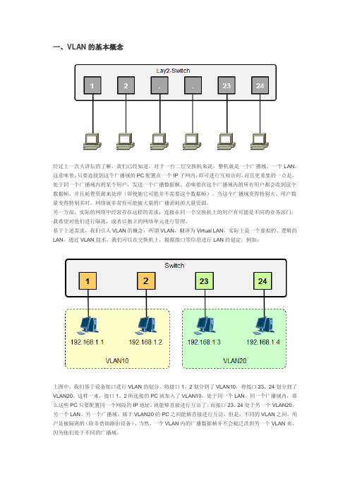
一、VLAN的基本概念经过上一次大讲坛的了解,我们已经知道,对于一台二层交换机来说,整机就是一个广播域、一个LAN。
这意味着,只要连接到这个广播域的PC配置在一个IP子网内,即可进行互相访问,而且更重要的一点是,处于同一个广播域内的某个用户,发送一个广播数据帧,意味着在这个广播域内的所有用户都会收到这个数据帧,并且耗费资源来处理(即使她它可能并不需要这个数据帧)。
当这个广播域变得特别大、用户数量变得特别多时,网络就非常有可能被大量的广播消耗掉大量资源。
另一方面,实际的网络中经常存在这样的需求:连接在同一个交换机上的用户有可能是不同的业务部门,我希望对他们进行隔离,或者以独立的网络单元进行管理。
基于上述需求,我们引入VLAN的概念,所谓VLAN,翻译为Virtual LAN,实际上是一个虚拟的、逻辑的LAN,通过VLAN技术,我们可以在交换机上,根据接口等信息进行LAN的划定。
例如:上图中,我们基于设备接口进行VLAN的划分。
将接口1、2划分到了VLAN10,将接口23、24划分到了VLAN20。
这样一来,接口1、2所连接的PC就加入了VLAN10,处于同一个LAN、同一个广播域内,那么这些PC只要配置同一个网段的IP地址,就能够直接进行互访了。
而接口23、24处于另一个VLAN20,另一个LAN、另一个广播域。
属于VLAN20的PC之间能够直接进行互访。
但是,不同的VLAN之间,用户是被隔离的(除非借助路由设备),当然,一个VLAN内的广播数据帧并不会被泛洪到另一个VLAN来,因为他们处于不同的广播域。
有了VLAN技术,我们的网络设计将更加灵活、更加可控。
VLAN是一个虚拟的LAN,不再受设备的限制。
我们可以根据实际的业务环境需要,灵活的进行VLAN的规划。
而VLAN更可以跨交换机,因此VLAN的成员,也就是业务PC所处的位置就非常灵活了。
例如上图所示,你可能希望每个部门单独划分到一个LAN 中,部分之间互相隔离,而一个部门的员工又往往未必在同一楼层,可能分散在不同的楼层,那么有了VLAN 技术,完全可以把分散在不同楼层的业务PC划分入一个VLAN。
计算机网络基础-TRUNK配置

Switch# show vlan id vlan-id
复习
Trunk的作用
❖如何实现交换机之间的VLAN通信
▪ 为每一个VLAN提供一条链路?
VLAN 10
VLAN 20
பைடு நூலகம்
如果有100 个VLAN怎 么办呢?
VLAN 10
VLAN 20
VLAN 30
VLAN 30
Trunk的作用2-2
配置以太网通道3-1
❖EthernetChannel-以太通道
▪ 多条线路负载均衡,带宽提高 ▪ 容错,当一条线路失效时,其他线路通信,不会丢包
配置为以太通道的接口, 必须物理特性相同
配置以太网通道3-2
❖配置接口为以太通道模式
Switch(config)# interface range fastEthernet 0/1 – 2
Name: Fa0/24
Switchport: Enabled
Administrative Mode: trunk
Operational Mode: trunk
…………
Operational private-vlan: none
Trunking VLANs Enabled: 1,3-1005
Pruning VLANs Enabled: 2-1001 Capture Mode Disabled
Operational private-vlan: none Trunking VLANs Enabled: ALL Pruning VLANs Enabled: 2-1001
Trunk可以承载所有的 VLAN
Capture Mode Disabled
vlan的配置方法

vlan的配置方法VLAN(Virtual Local Area Network,虚拟局域网)是一种将一个物理网络划分成多个逻辑上的虚拟网络的技术,它可以提供更好的网络性能、安全性和管理灵活性。
在进行VLAN的配置时,需要按照一定的步骤进行操作,下面将详细介绍VLAN的配置方法。
1. 确定VLAN的划分方案在配置VLAN之前,需要先确定VLAN的划分方案。
可以根据不同的需求和网络拓扑结构,将网络划分为不同的VLAN,如按照部门、功能或地理位置等进行划分。
确定划分方案后,可以开始进行VLAN的配置。
2. 创建VLAN在交换机上创建VLAN是配置VLAN的第一步。
可以通过以下命令在交换机上创建VLAN:```Switch(config)# vlan vlan_id```其中,vlan_id为VLAN的标识符,可以根据实际需求进行设置。
创建VLAN后,可以通过以下命令查看已创建的VLAN列表:```Switch# show vlan```3. 配置接口创建VLAN后,需要将交换机的接口与相应的VLAN进行关联。
可以通过以下命令将接口划分到指定的VLAN:```Switch(config)# interface interface_idSwitch(config-if)# switchport mode accessSwitch(config-if)# switchport access vlan vlan_id```其中,interface_id为接口的标识符,可以是物理接口、端口通道或VLAN接口。
vlan_id为要划分到的VLAN的标识符。
配置完成后,可以通过以下命令查看接口的VLAN配置情况:```Switch# show interfaces interface_id switchport```4. 配置Trunk接口如果需要在不同的交换机之间传输多个VLAN的数据,就需要配置Trunk接口。
交换机的TRUNK解释与配置详解

交换机的TRUNK解释与配置详解在二层交换机的性能参数中,常常提到一个重要的指标:TRUNK,许多的二层交换机产品在介绍其性能时,都会提到能够支持TRUNK功能,从而可以为互连的交换机之间提供更好的传输性能。
那到底什么是TRUNK呢?使用TRUNK功能到底能给我们带来哪些应用方面的优势?还有在具体的交换机产品中怎样来配置TRUNK。
VLAN Trunk的作用是让连接在不同交换机上的相同VLAN中的主机互通。
如果两台交换机都设置有同一VLAN里的计算机,怎么办呢,我们可以通过VLAN Trunk来解决。
如果交换机1的VLAN1中的机器要访问交换机2的VLAN1中的机器,我们可以把两台交换机的级联端口设置为Trunk端口,这样,当交换机把数据包从级联口发出去的时候,会在数据包中做一个标记(TAG),以使其它交换机识别该数据包属于哪一个VLAN,这样,其它交换机收到这样一个数据包后,只会将该数据包转发到标记中指定的VLAN,从而完成了跨越交换机的VLAN内部数据传输。
VLAN Trunk目前有两种标准,ISL和802.1q,前者是Cisco专有技术,后者则是IEEE的国际标准,除了Cisco两者都支持外,其它厂商都只支持后者。
一、什么是TRUNK?TRUNK是端口汇聚的意思,就是通过配置软件的设置,将2个或多个物理端口组合在一起成为一条逻辑的路径从而增加在交换机和网络节点之间的带宽,将属于这几个端口的带宽合并,给端口提供一个几倍于独立端口的独享的高带宽。
Trunk是一种封装技术,它是一条点到点的链路,链路的两端可以都是交换机,也可以是交换机和路由器,还可以是主机和交换机或路由器。
基于端口汇聚(Trunk)功能,允许交换机与交换机、交换机与路由器、主机与交换机或路由器之间通过两个或多个端口并行连接同时传输以提供更高带宽、更大吞吐量,大幅度提供整个网络能力。
一般情况下,在没有使用TRUNK时,大家都知道,百兆以太网的双绞线的这种传输介质特性决定在两个互连的普通10/100交换机的带宽仅为100M,如果是采用的全双工模式的话,则传输的最大带宽可以达到最大200M,这样就形成了网络主干和服务器瓶颈。
VLAN的划分和trunk链路的配置

VLAN的划分和TRUNK链路的配置一、VLAN划分1、VLAN的作用: VLAN,是英文Virtual Local Area Network的缩写,中文名为"虚拟局域网",VLAN是一种将局域网(LAN)设备从逻辑上划分成一个个网段(或者说是更小的局域网LAN),从而实现虚拟工作组(单元)的数据交换技术。
2、实验拓扑图3、实验步骤及命令○1设置四台PC 的IP地址和子网掩码○2将PC1和PC2划分在VLAN10中第一台交换机命令:Switch>enSwitch#conf tEnter configuration commands, one per line. End with CNTL/Z. Switch(config)#vlan 10Switch(config-vlan)#exitSwitch(config)#int f0/1Switch(config-if)#switchport access vlan 10第二台交换机命令:Switch>enSwitch#conf tEnter configuration commands, one per line. End with CNTL/Z. Switch(config)#vlan 10Switch(config-vlan)#exitSwitch(config)#int f0/1Switch(config-if)#switchport access vlan 10○3将PC3和PC4划分到VLAN20中第一台交换机命令:Switch>enSwitch#conf tEnter configuration commands, one per line. End with CNTL/Z. Switch(config)#vlan 20Switch(config-vlan)#exitSwitch(config)#int f0/10Switch(config-if)#switchport access vlan 20第二台交换机命令:Switch>enSwitch#conf tEnter configuration commands, one per line. End with CNTL/Z. Switch(config)#vlan 20Switch(config-vlan)#exitSwitch(config)#int f0/10Switch(config-if)#switchport access vlan 20 4、检测连通性二、Trunk链路:带宽。
全面介绍核心交换机TRUNK配置功能

全面介绍核心交换机TRUNK配置功能核心交换机是局域网中最重要的设备之一,它连接其他交换机、路由器和终端设备,负责处理网络数据的传输和路由。
在核心交换机的配置中,其中一个重要的功能是配置TRUNK。
TRUNK是一个术语,用来描述交换机之间的特殊端口配置,允许通过单个物理链路传送多个虚拟局域网(VLAN)的数据。
TRUNK连接通常在网络中的核心交换机之间建立,以提供更高的带宽和灵活性。
在进行TRUNK配置之前,需要了解一些与TRUNK相关的概念和术语。
1.交换机端口类型:- Access端口:用于连接终端设备,只能属于一个VLAN。
-TRUNK端口:用于连接交换机,可以传输多个VLAN的数据。
2. VLAN(Virtual Local Area Network):一种逻辑上独立的网络,它可以将不同的终端设备划分到不同的虚拟网络中,相互之间互不干扰。
下面是一些常见的核心交换机TRUNK配置功能:1.配置TRUNK端口:-进入核心交换机的命令行界面,并进入相应端口的配置模式。
- 使用命令“switchport mode trunk”将端口配置为TRUNK模式。
2.配置允许的VLAN:- 使用命令“switchport trunk allowed vlan”配置允许通过TRUNK端口的VLAN列表。
- 可以使用范围、逗号分隔或者all关键字来指定允许的VLAN。
3.配置本地VLAN与远程VLAN的映射:- 使用命令“switchport trunk native vlan”配置本地VLAN。
- 使用命令“switchport trunk allowed vlan add”添加需要映射的远程VLAN。
4.配置TRUNK链路协议:- 通过命令“switchport trunk encapsulation”指定数据链路层的封装协议,如802.1Q或ISL。
-可以使用默认值或手动指定。
5.配置TRUNK链路管理协议:- 使用命令“switchport trunk allowed vlan add”添加需要映射的远程VLAN。
关于LAN网内VLAN与Trunk的详细配置
关于LAN网内VLAN与Trunk的详细配置此实验过程是在Boson NetSim for CCNP version 6.0 BETA 1软件下做的。
其中使用2台C2905switch和4台PC机。
实验内容:1、配置控制端口和虚拟线路2、设置VLAN两个,分别为:VLAN100 Pcontrol和VLAN200 Accout3、分别将接口加入到VLAN100和VLAN200后配置Trunk线路,保证VLAN间的通信4、最后进行测试是否成功关于LAN网内VLAN与Trunk的详细配置SW1(C2950)交换机测试详细步骤及结果:CLI session with the switch is open.To end the CLI session, enter [Exit].Switch>%LINK-3-UPDOWN: Interface FastEthernet0/1, changed state to down%LINEPROTO-5-UPDOWN: Line protocol on Interface FastEthernet0/1, changed state to down %LINK-3-UPDOWN: Interface FastEthernet0/4, changed state to down%LINEPROTO-5-UPDOWN: Line protocol on Interface FastEthernet0/4, changed state to down %LINK-3-UPDOWN: Interface FastEthernet0/5, changed state to down%LINEPROTO-5-UPDOWN: Line protocol on Interface FastEthernet0/5, changed state to down %LINK-3-UPDOWN: Interface FastEthernet0/6, changed state to down%LINEPROTO-5-UPDOWN: Line protocol on Interface FastEthernet0/6, changed state to down %LINK-3-UPDOWN: Interface FastEthernet0/7, changed state to down%LINEPROTO-5-UPDOWN: Line protocol on Interface FastEthernet0/7, changed state to down %LINK-3-UPDOWN: Interface FastEthernet0/8, changed state to down%LINEPROTO-5-UPDOWN: Line protocol on Interface FastEthernet0/8, changed state to down %LINK-3-UPDOWN: Interface FastEthernet0/9, changed state to down%LINEPROTO-5-UPDOWN: Line protocol on Interface FastEthernet0/9, changed state to down %LINK-3-UPDOWN: Interface FastEthernet0/11, changed state to down%LINEPROTO-5-UPDOWN: Line protocol on Interface FastEthernet0/11, changed state to down %LINK-3-UPDOWN: Interface FastEthernet0/12, changed state to down%LINEPROTO-5-UPDOWN: Line protocol on Interface FastEthernet0/12, changed state to down Switch>enableSwitch#show versionBoson Operating Simulation SoftwareBOSS (tm) C2900 Software (C2900-Enterprise), Version 12.1, RELEASE SOFTWARE Copyright (c) 1998-2003 by Boson Software, Inc.BOSS ROM: System Bootstrap, Version 12.2, RELEASE SOFTWARESwitch Uptime Is 0 days, 0 hours, 0 minutesSystem restarted by power-onSystem image file is ""flash:c2900-enterprise.12.1.boss"", booted via flashBoson 2900 (BOSS) processor (revision 5.0)12 FastEthernet/IEEE 802.3 interface(s)32K bytes of simulated non-volatile configuration memory.8192K bytes of simulated System flash (Read/Write)Switch#Switch#Switch#show runn!Version 12.1service timestamps debug uptimeservice timestamps log uptimeno service password-encryption!hostname Switch!!!ip subnet-zerospanning-tree extend system-id!!!!!!!!interface FastEthernet0/1!interface FastEthernet0/2Switch#show runn!Version 12.1service timestamps debug uptime service timestamps log uptime no service password-encryption !hostname Switch!!!ip subnet-zerospanning-tree extend system-id !!!!!!!!interface FastEthernet0/1!interface FastEthernet0/2!interface FastEthernet0/3!interface FastEthernet0/4!interface FastEthernet0/5!interface FastEthernet0/6!interface FastEthernet0/7!interface FastEthernet0/8!interface FastEthernet0/9!interface FastEthernet0/10!interface FastEthernet0/11interface FastEthernet0/12!vtp domain bigdomain!interface Vlan 1no ip addressno ip route-cache!!ip classlessno ip http server!!!!line con 0transport input noneline aux 0line vty 0 15!no scheduler allocateendSwitch#Switch#Switch#configure terminalEnter configuration commands, one per line. End with CNTL/Z. Switch(config)#hostname SW1SW1(config)#line console 0SW1(config-line)#exec-timeout 20 0SW1(config-line)#logging synchronousSW1(config-line)#password dsfengSW1(config-line)#loginSW1(config-line)#line vty 0 15SW1(config-line)#exec-timeout 15 0SW1(config-line)#logging synchronousSW1(config-line)#password dsfengSW1(config-line)#loginSW1(config-line)#enable secret ciscoSW1(config)#exitSW1#SW1#SW1#vlan databaseSW1(vlan)#vlan 100 name PcontrolVLAN 100 added:Name:PcontrolSW1(vlan)#vlan 200 name AccoutVLAN 200 added:Name:AccoutSW1(vlan)#exitAPPL Y completed.Exiting....SW1#SW1#SW1#configure terminalEnter configuration commands, one per line. End with CNTL/Z.SW1(config)#interface fastethernet 0/2SW1(config-if)#switchport mode accessSW1(config-if)#switchport access vlan 100SW1(config-if)#exitSW1(config)#interface fastethernet 0/3SW1(config-if)#switchport mode accessSW1(config-if)#switchport access vlan 200SW1(config-if)#exitSW1(config)#interface fasteterhent 0/10SW1(config-if)#switchport mode trunkSW1(config-if)#switchport trunk encapsulation dot1qSW1(config-if)#endSW1#SW1#SW1#show interface fastethernet 0/2FastEthernet0/2 is up, line protocol is upHardware is Fast Ethernet, address is 000C.6542.9093 (bia 000C.6542.9093) MTU 1500 bytes, BW 10000 Kbit, DL Y 1000 usec,reliability 255/255, txload 1/255, rxload 1/255Auto-duplex, Auto-speedEncapsulation ARPA, loopback not setARP type: ARPA, ARP Timeout 04:00:00Last input 02:29:44, output never, output hang neverLast clearing of "show interface" counters neverInput queue: 0/75/0/0 (size/max/drops/flushes); Total output drops: 0 Queueing strategy: fifoOutput queue :0/40 (size/max)5 minute input rate 0 bits/sec, 0 packets/sec5 minute output rate 0 bits/sec, 0 packets/sec269 packets input, 71059 bytes, 0 no bufferReceived 6 broadcasts, 0 runts, 0 giants, 0 throttles0 input errors, 0 CRC, 0 frame, 0 overrun, 0 ignored7290 packets output, 429075 bytes, 0 underruns0 output errors, 3 interface resets0 output buffer failures, 0 output buffers swapped outSW1#SW1#SW1#show interface fastethernet 0/3FastEthernet0/3 is up, line protocol is upHardware is Fast Ethernet, address is 000C.3849.2796 (bia 000C.3849.2796) MTU 1500 bytes, BW 10000 Kbit, DL Y 1000 usec,reliability 255/255, txload 1/255, rxload 1/255Auto-duplex, Auto-speedEncapsulation ARPA, loopback not setARP type: ARPA, ARP Timeout 04:00:00Last input 02:29:44, output never, output hang neverLast clearing of "show interface" counters neverInput queue: 0/75/0/0 (size/max/drops/flushes); Total output drops: 0 Queueing strategy: fifoOutput queue :0/40 (size/max)5 minute input rate 0 bits/sec, 0 packets/sec5 minute output rate 0 bits/sec, 0 packets/sec269 packets input, 71059 bytes, 0 no bufferReceived 6 broadcasts, 0 runts, 0 giants, 0 throttles0 input errors, 0 CRC, 0 frame, 0 overrun, 0 ignored7290 packets output, 429075 bytes, 0 underruns0 output errors, 3 interface resets0 output buffer failures, 0 output buffers swapped outSW1#SW1#SW1#show interface fastethernet 0/10FastEthernet0/10 is up, line protocol is upHardware is Fast Ethernet, address is 000C.3878.9745 (bia 000C.3878.9745) MTU 1500 bytes, BW 10000 Kbit, DL Y 1000 usec,reliability 255/255, txload 1/255, rxload 1/255Auto-duplex, Auto-speedEncapsulation ARPA, loopback not setARP type: ARPA, ARP Timeout 04:00:00Last input 02:29:44, output never, output hang neverLast clearing of "show interface" counters neverInput queue: 0/75/0/0 (size/max/drops/flushes); Total output drops: 0 Queueing strategy: fifoOutput queue :0/40 (size/max)5 minute input rate 0 bits/sec, 0 packets/sec5 minute output rate 0 bits/sec, 0 packets/sec269 packets input, 71059 bytes, 0 no bufferReceived 6 broadcasts, 0 runts, 0 giants, 0 throttles0 input errors, 0 CRC, 0 frame, 0 overrun, 0 ignored7290 packets output, 429075 bytes, 0 underruns0 output errors, 3 interface resets0 output buffer failures, 0 output buffers swapped outSW1#SW1#SW1#show vlanVLAN Name Status Ports---- -------------------------------- --------- -------------------------------1 default active Fa0/1, Fa0/4, Fa0/5, Fa0/6Fa0/7, Fa0/8, Fa0/9, Fa0/10Fa0/11, Fa0/12100 Pcontrol active Fa0/2200 Accout active Fa0/31002 fddi-default active1003 token-ring-default active1004 fddinet-default active1005 trnet-default activeVLAN Type SAID MTU Parent RingNo BridgeNo Stp BrdgMode Trans1 Trans2 ---- ----- ---------- ----- ------ ------ -------- ---- -------- ------ ------1 enet 100001 1500 - - - - - 0 0100 enet 100100 1500 - - - - - 0 0200 enet 100200 1500 - - - - - 0 01002 fddi 101002 1500 - - - - - 0 01003 tr 101003 1500 - - - - - 0 01004 fdnet 101004 1500 - - - ieee - 0 01005 trnet 101005 1500 - - - ibm - 0 0SW1#SW1#SW1#show cdp neighborsCapability Codes: R - Router, T - Trans Bridge, B - Source Route BridgeS -Switch, H - Host, i - IGMP, r - RepeaterDevice ID Local Intrfce Holdtme Capability Platform Port IDSW2 Fas0/10 167 T S 2950 Fas 0/10SW1#SW1#SW1#show mac-address-tableCapability Codes: R - Router, T - Trans Bridge, B - Source Route BridgeS -Switch, H - Host, i - IGMP, r - RepeaterDevice ID Local Intrfce Holdtme Capability Platform Port IDSW2 Fas0/10 167 T S 2950 Fas 0/10Mac Address Table------------------------------------------Vlan Mac Address Type Ports---- ----------- ---- -----200 000C.9631.1997 DYNAMIC Fa0/3100 000C.7036.8702 DYNAMIC Fa0/21 000C.3817.8412 DYNAMIC Fa0/101 000C.9623.5011 DYNAMIC Fa0/101 000C.1738.3819 DYNAMIC Fa0/10Total Mac Addresses for this criterion: 5SW1#SW1#SW1#show run!Version 12.1service timestamps debug uptimeservice timestamps log uptimeno service password-encryption!hostname SW1enable secret 5 $sdf$6978yhg$jnb76sd!!!ip subnet-zerospanning-tree extend system-id!!!!!!!!interface FastEthernet0/1!interface FastEthernet0/2 switchport mode access switchport access vlan 100!interface FastEthernet0/3 switchport mode access switchport access vlan 200!interface FastEthernet0/4!interface FastEthernet0/5!interface FastEthernet0/6!interface FastEthernet0/7!interface FastEthernet0/8!interface FastEthernet0/9!interface FastEthernet0/10 switchport mode trunkswitchport trunk encapsulation dot1q !interface FastEthernet0/11!interface FastEthernet0/12!vtp domain bigdomain!interface Vlan 1no ip addressno ip route-cache!vlan 100 name Pcontrolvlan 200 name Accout!ip classlessno ip http server!!!!line con 0logintransport input nonepassword dsfengexec-timeout 15 0logging synchronousline aux 0line vty 0 15loginpassword dsfeng!no scheduler allocateendSW1#SW1#SW1#copy running-config startup-configDestination filename [startup-config]?Building configuration...[OK]SW1#SW1#SW2(C2950)交换机测试详细步骤及结果:CLI session with the switch is open.To end the CLI session, enter [Exit].%LINK-3-UPDOWN: Interface FastEthernet0/1, changed state to down%LINEPROTO-5-UPDOWN: Line protocol on Interface FastEthernet0/1, changed state to down %LINK-3-UPDOWN: Interface FastEthernet0/4, changed state to down%LINEPROTO-5-UPDOWN: Line protocol on Interface FastEthernet0/4, changed state to down %LINK-3-UPDOWN: Interface FastEthernet0/5, changed state to down%LINEPROTO-5-UPDOWN: Line protocol on Interface FastEthernet0/5, changed state to down %LINK-3-UPDOWN: Interface FastEthernet0/6, changed state to down%LINEPROTO-5-UPDOWN: Line protocol on Interface FastEthernet0/6, changed state to down %LINK-3-UPDOWN: Interface FastEthernet0/7, changed state to down%LINEPROTO-5-UPDOWN: Line protocol on Interface FastEthernet0/7, changed state to down %LINK-3-UPDOWN: Interface FastEthernet0/8, changed state to down%LINEPROTO-5-UPDOWN: Line protocol on Interface FastEthernet0/8, changed state to down %LINK-3-UPDOWN: Interface FastEthernet0/9, changed state to down%LINEPROTO-5-UPDOWN: Line protocol on Interface FastEthernet0/9, changed state to down %LINK-3-UPDOWN: Interface FastEthernet0/11, changed state to down%LINEPROTO-5-UPDOWN: Line protocol on Interface FastEthernet0/11, changed state to down %LINK-3-UPDOWN: Interface FastEthernet0/12, changed state to down%LINEPROTO-5-UPDOWN: Line protocol on Interface FastEthernet0/12, changed state to down Switch>Switch>enableSwitch#show versionBoson Operating Simulation SoftwareBOSS (tm) C2900 Software (C2900-Enterprise), Version 12.1, RELEASE SOFTWARE Copyright (c) 1998-2003 by Boson Software, Inc.BOSS ROM: System Bootstrap, Version 12.2, RELEASE SOFTWARESwitch Uptime Is 0 days, 0 hours, 5 minutesSystem restarted by power-onSystem image file is ""flash:c2900-enterprise.12.1.boss"", booted via flashBoson 2900 (BOSS) processor (revision 5.0)12 FastEthernet/IEEE 802.3 interface(s)32K bytes of simulated non-volatile configuration memory.8192K bytes of simulated System flash (Read/Write)Switch#Switch#Switch#show runn!Version 12.1service timestamps debug uptimeservice timestamps log uptimeno service password-encryption!hostname Switch!!!ip subnet-zerospanning-tree extend system-id !!!!!!!!interface FastEthernet0/1!interface FastEthernet0/2!interface FastEthernet0/3!interface FastEthernet0/4!interface FastEthernet0/5!interface FastEthernet0/6!interface FastEthernet0/7!interface FastEthernet0/8!interface FastEthernet0/9!interface FastEthernet0/10!interface FastEthernet0/11!interface FastEthernet0/12!vtp domain bigdomain!interface Vlan 1no ip addressno ip route-cache!!ip classlessno ip http server!!!!line con 0transport input noneline aux 0line vty 0 15!no scheduler allocateendSwitch#Switch#Switch#configure terminalEnter configuration commands, one per line. End with CNTL/Z. Switch(config)#hostname SW2SW2(config)#line console 0SW2(config-line)#exec-timeout 20 0SW2(config-line)#logging synchronousSW2(config-line)#password dsfengSW2(config-line)#loginSW2(config-line)#line vty 0 15SW2(config-line)#exec-timeout 15 0SW2(config-line)#logging synchronousSW2(config-line)#password dsfengSW2(config-line)#loginSW2(config-line)#enable secret ciscoSW2(config)#endSW2#SW2#SW2#vlan databaseSW2(vlan)#vlan 100 name PcontrolVLAN 100 added:Name:PcontrolSW2(vlan)#vlan 200 name AccoutVLAN 200 added:Name:AccoutSW2(vlan)#exitAPPL Y completed.Exiting....SW2#SW2#SW2#configure terminalEnter configuration commands, one per line. End with CNTL/Z.SW2(config)#interface fastethernet 0/2SW2(config-if)#switchport mode accessSW2(config-if)#switchport access vlan 100SW2(config-if)#exitSW2(config)#interface fastethernet 0/3SW2(config-if)#switchport mode accessSW2(config-if)#switchport access vlan 200SW2(config-if)#exitSW2(config)#interface fastethernet 0/10SW2(config-if)#switchport mode trunkSW2(config-if)#switchport trunk encapsulation dot1qSW2(config-if)#endSW2#SW2#SW2#show interface fastethernet 0/2FastEthernet0/2 is up, line protocol is upHardware is Fast Ethernet, address is 000C.2018.9057 (bia 000C.2018.9057) MTU 1500 bytes, BW 10000 Kbit, DL Y 1000 usec,reliability 255/255, txload 1/255, rxload 1/255Auto-duplex, Auto-speedEncapsulation ARPA, loopback not setARP type: ARPA, ARP Timeout 04:00:00Last input 02:29:44, output never, output hang neverLast clearing of "show interface" counters neverInput queue: 0/75/0/0 (size/max/drops/flushes); Total output drops: 0 Queueing strategy: fifoOutput queue :0/40 (size/max)5 minute input rate 0 bits/sec, 0 packets/sec5 minute output rate 0 bits/sec, 0 packets/sec269 packets input, 71059 bytes, 0 no bufferReceived 6 broadcasts, 0 runts, 0 giants, 0 throttles0 input errors, 0 CRC, 0 frame, 0 overrun, 0 ignored7290 packets output, 429075 bytes, 0 underruns0 output errors, 3 interface resets0 output buffer failures, 0 output buffers swapped outSW2#SW2#SW2#show interface fastethernet 0/3FastEthernet0/3 is up, line protocol is upHardware is Fast Ethernet, address is 000C.4287.4991 (bia 000C.4287.4991) MTU 1500 bytes, BW 10000 Kbit, DL Y 1000 usec,reliability 255/255, txload 1/255, rxload 1/255Auto-duplex, Auto-speedEncapsulation ARPA, loopback not setARP type: ARPA, ARP Timeout 04:00:00Last input 02:29:44, output never, output hang neverLast clearing of "show interface" counters neverInput queue: 0/75/0/0 (size/max/drops/flushes); Total output drops: 0 Queueing strategy: fifoOutput queue :0/40 (size/max)5 minute input rate 0 bits/sec, 0 packets/sec5 minute output rate 0 bits/sec, 0 packets/sec269 packets input, 71059 bytes, 0 no bufferReceived 6 broadcasts, 0 runts, 0 giants, 0 throttles0 input errors, 0 CRC, 0 frame, 0 overrun, 0 ignored7290 packets output, 429075 bytes, 0 underruns0 output errors, 3 interface resets0 output buffer failures, 0 output buffers swapped outSW2#SW2#SW2#show interface fastethernet 0/10FastEthernet0/10 is up, line protocol is upHardware is Fast Ethernet, address is 000C.3817.8412 (bia 000C.3817.8412) MTU 1500 bytes, BW 10000 Kbit, DL Y 1000 usec,reliability 255/255, txload 1/255, rxload 1/255Auto-duplex, Auto-speedEncapsulation ARPA, loopback not setARP type: ARPA, ARP Timeout 04:00:00Last input 02:29:44, output never, output hang neverLast clearing of "show interface" counters neverInput queue: 0/75/0/0 (size/max/drops/flushes); Total output drops: 0 Queueing strategy: fifoOutput queue :0/40 (size/max)5 minute input rate 0 bits/sec, 0 packets/sec5 minute output rate 0 bits/sec, 0 packets/sec269 packets input, 71059 bytes, 0 no bufferReceived 6 broadcasts, 0 runts, 0 giants, 0 throttles0 input errors, 0 CRC, 0 frame, 0 overrun, 0 ignored7290 packets output, 429075 bytes, 0 underruns0 output errors, 3 interface resets0 output buffer failures, 0 output buffers swapped outSW2#SW2#SW2#show vlanVLAN Name Status Ports---- -------------------------------- --------- -------------------------------1 default active Fa0/1, Fa0/4, Fa0/5, Fa0/6Fa0/7, Fa0/8, Fa0/9, Fa0/10Fa0/11, Fa0/12100 Pcontrol active Fa0/2200 Accout active Fa0/31002 fddi-default active1003 token-ring-default active1004 fddinet-default active1005 trnet-default activeVLAN Type SAID MTU Parent RingNo BridgeNo Stp BrdgMode Trans1 Trans2 ---- ----- ---------- ----- ------ ------ -------- ---- -------- ------ ------1 enet 100001 1500 - - - - - 0 0100 enet 100100 1500 - - - - - 0 0200 enet 100200 1500 - - - - - 0 01002 fddi 101002 1500 - - - - - 0 01003 tr 101003 1500 - - - - - 0 01004 fdnet 101004 1500 - - - ieee - 0 01005 trnet 101005 1500 - - - ibm - 0 0SW2#SW2#SW2#show mac-address-tableVLAN Name Status Ports---- -------------------------------- --------- -------------------------------1 default active Fa0/1, Fa0/4, Fa0/5, Fa0/6Fa0/7, Fa0/8, Fa0/9, Fa0/10Fa0/11, Fa0/12100 Pcontrol active Fa0/2200 Accout active Fa0/31002 fddi-default active1003 token-ring-default active1004 fddinet-default active1005 trnet-default activeVLAN Type SAID MTU Parent RingNo BridgeNo Stp BrdgMode Trans1 Trans2 ---- ----- ---------- ----- ------ ------ -------- ---- -------- ------ ------1 enet 100001 1500 - - - - - 0 0100 enet 100100 1500 - - - - - 0 0 200 enet 100200 1500 - - - - - 0 0 1002 fddi 101002 1500 - - - - - 0 0 1003 tr 101003 1500 - - - - - 0 0 1004 fdnet 101004 1500 - - - ieee - 0 0 1005 trnet 101005 1500 - - - ibm - 0 0Mac Address Table------------------------------------------Vlan Mac Address Type Ports---- ----------- ---- -----200 000C.1738.3819 DYNAMIC Fa0/3100 000C.9623.5011 DYNAMIC Fa0/21 000C.3878.9745 DYNAMIC Fa0/101 000C.7036.8702 DYNAMIC Fa0/101 000C.9631.1997 DYNAMIC Fa0/10Total Mac Addresses for this criterion: 5SW2#SW2#SW2#show runn!Version 12.1service timestamps debug uptimeservice timestamps log uptimeno service password-encryption!hostname SW2enable secret 5 $sdf$6978yhg$jnb76sd!!!ip subnet-zerospanning-tree extend system-id!!!!!!!!interface FastEthernet0/1!interface FastEthernet0/2 switchport mode access switchport access vlan 100!interface FastEthernet0/3 switchport mode access switchport access vlan 200!interface FastEthernet0/4!interface FastEthernet0/5!interface FastEthernet0/6!interface FastEthernet0/7!interface FastEthernet0/8!interface FastEthernet0/9!interface FastEthernet0/10 switchport mode trunkswitchport trunk encapsulation dot1q !interface FastEthernet0/11!interface FastEthernet0/12!vtp domain bigdomain!interface Vlan 1no ip addressno ip route-cache!vlan 100 name Pcontrolvlan 200 name Accout!ip classlessno ip http server!!!!line con 0logintransport input nonepassword dsfengexec-timeout 15 0logging synchronousline aux 0line vty 0 15loginpassword dsfeng!no scheduler allocateendSW2#SW2#SW2#copy running-config startup-configDestination filename [startup-config]?Building configuration...[OK]SW2#SW2#PC1测试结果:Boson BOSS 5.0Copyright 1998-2005 Boson Software, Inc.Use the command help to get startedPress Enter to beginC:>C:>ipconfig /ip 192.168.1.1 255.255.255.0C:>ping 192.168.1.2Pinging 192.168.1.2 with 32 bytes of data:Reply from 192.168.1.2: bytes=32 time=60ms TTL=241 Reply from 192.168.1.2: bytes=32 time=60ms TTL=241Reply from 192.168.1.2: bytes=32 time=60ms TTL=241Reply from 192.168.1.2: bytes=32 time=60ms TTL=241Reply from 192.168.1.2: bytes=32 time=60ms TTL=241Ping statistics for 192.168.1.2: Packets: Sent = 5, Received = 5, Lost = 0 (0% loss), Approximate round trip times in milli-seconds:Minimum = 50ms, Maximum = 60ms, Average = 55msPC2测试结果:Boson BOSS 5.0Copyright 1998-2005 Boson Software, Inc.Use the command help to get startedPress Enter to beginC:>ipconfig /ip 192.168.10.1 255.255.255.0C:>C:>ping 192.168.10.2Pinging 192.168.10.2 with 32 bytes of data:Reply from 192.168.10.2: bytes=32 time=60ms TTL=241Reply from 192.168.10.2: bytes=32 time=60ms TTL=241Reply from 192.168.10.2: bytes=32 time=60ms TTL=241Reply from 192.168.10.2: bytes=32 time=60ms TTL=241Reply from 192.168.10.2: bytes=32 time=60ms TTL=241Ping statistics for 192.168.10.2: Packets: Sent = 5, Received = 5, Lost = 0 (0% loss), Approximate round trip times in milli-seconds:Minimum = 50ms, Maximum = 60ms, Average = 55msPC3测试结果:Boson BOSS 5.0Copyright 1998-2005 Boson Software, Inc.Use the command help to get startedPress Enter to beginC:>ipconfig /ip 192.168.1.2 255.255.255.0C:>ping 192.168.1.1Pinging 192.168.1.1 with 32 bytes of data:Reply from 192.168.1.1: bytes=32 time=60ms TTL=241Reply from 192.168.1.1: bytes=32 time=60ms TTL=241Reply from 192.168.1.1: bytes=32 time=60ms TTL=241Reply from 192.168.1.1: bytes=32 time=60ms TTL=241Reply from 192.168.1.1: bytes=32 time=60ms TTL=241Ping statistics for 192.168.1.1: Packets: Sent = 5, Received = 5, Lost = 0 (0% loss), Approximate round trip times in milli-seconds:Minimum = 50ms, Maximum = 60ms, Average = 55msPC4测试结果:Boson BOSS 5.0Copyright 1998-2005 Boson Software, Inc.Use the command help to get startedPress Enter to beginC:>ipconfig /ip 192.168.10.2 255.255.255.0C:>ping 192.168.10.1Pinging 192.168.10.1 with 32 bytes of data:Reply from 192.168.10.1: bytes=32 time=60ms TTL=241Reply from 192.168.10.1: bytes=32 time=60ms TTL=241Reply from 192.168.10.1: bytes=32 time=60ms TTL=241Reply from 192.168.10.1: bytes=32 time=60ms TTL=241Reply from 192.168.10.1: bytes=32 time=60ms TTL=241Ping statistics for 192.168.10.1: Packets: Sent = 5, Received = 5, Lost = 0 (0% loss), Approximate round trip times in milli-seconds:Minimum = 50ms, Maximum = 60ms, Average = 55ms。
《计算机网络》上机任务书 - 实验二
《计算机网络》上机任务书实验二VLAN设置一.实验目的:掌握以太网的工作原理掌握交换机上创建VLAN、分配静态VLAN成员的方法掌握交换机上创建trunk的方法,利用trunk实现跨交换机VLAN内的通信通过一个三层交换机的第三层路由交换技术,实现多个VLAN之间的通信。
二.实验要点:1.配置两个VLAN:VLAN 2和VLAN 3并为其分配静态成员。
2.查看VLAN分配结果。
3. 测试VLAN分配的连通情况。
4. 测试几个VLAN间的连通情况。
三.实验设备:Cisco交换机CATALYST 2960一台~二台,Swithc_3560 1台,主机PC多台(至少两台),控制台电缆一条。
四、实验任务1、任务一:熟悉交换机基本工作原理,掌握交换机常用设置命令;(注意各种命令所处的工作模式)从用户模式进入进入特权模式:Enable进入配置模式:Configure terminal(可简写为config t)修改交换机名称:Hostname name退出配置模式,返回特权模式:Exit显示当前活动的交换机配置文件:Show running-config显示接口1 的统计和状态信息:Show interface f0/1查看vlan 信息Show vlan(其中vlan1 是默认的管理vlan,未对交换机进行配置时所有的接口默认属于vlan1)查看flash 缓存内容Show flash查看IOS 版本号以及系统硬件的配置情况、引导镜像等:Show version恢复交换机到默认设置:Erase startup-config //删除备份配置文件Reload //重新启动交换机配置主机名称和控制端密码:Hostname SwitchALine console 0Passwod 123456LoginLine vty 0 15Password 123456Login为二层交换机设置管理IP地址(192.168.1.1)、子网掩码(255.255.255.0)、默认网关(192.168.1.254):Interface vlan 1Ip address 192.168.1.1 255.255.255.0No shutdownExitIp default-gateway 192.168.1.254Exit查看配置后的默认vlan 虚接口信息Show interface vlan 1查看mac 地址表Show mac-address-table*配置交换机主机名(SwitchA)、加密使能密码(S1)、虚拟终端口令(S2)及超时时间(5分钟)、禁止名称解析服务。
基于trunk端口划分vlan的基本配置

基于trunk端口划分vlan的基本配置基于trunk端口划分VLAN的基本配置是网络管理员必须了解和掌握的重要技能之一。
VLAN(虚拟局域网)是一种将物理网络划分成逻辑上独立的多个网络的技术。
通过将不同的设备和用户分配到不同的VLAN中,可以实现网络资源的灵活分配和管理。
本文将以基于trunk端口划分VLAN的基本配置为主题,逐步回答相关问题,帮助读者了解和掌握这一技能。
一、什么是trunk端口?Trunk端口是一种可以传输多个VLAN数据的端口。
它可以将来自不同VLAN的数据打包封装,通过一个物理链路传输到其他设备,从而实现VLAN之间的通信。
二、为什么需要使用trunk端口?在实际网络中,通常会有多个VLAN,而这些VLAN之间需要进行通信。
如果不使用trunk端口,每个VLAN将被限制在各自的物理链路中,无法实现互相连接。
而使用trunk端口,能够将多个VLAN的数据打包封装在一个物理链路中传输,从而提高网络的灵活性和可管理性。
三、如何配置trunk端口划分VLAN?1. 确认网络拓扑:首先,需要了解网络的拓扑结构,包括设备和链路的连接关系。
2. 配置VLAN:在交换机上创建所需的VLAN,可以通过VLAN ID来标识不同的VLAN。
3. 配置trunk端口:确定哪些端口需要配置为trunk端口。
进入交换机的配置模式,找到相应的端口,输入命令“switchport mode trunk”来将端口配置为trunk模式。
4. 配置允许的VLAN:在trunk端口上,需要配置允许传输的VLAN。
可以使用命令“switchport trunk allowed vlan”+“VLAN ID”的方式来配置允许传输的VLAN,可以同时配置多个VLAN。
5. 验证配置:使用命令“show interfaces trunk”来验证trunk端口的配置,确认配置已经生效。
四、trunk端口配置注意事项1. 确保网络拓扑准确无误:配置trunk端口前,必须清楚网络的拓扑结构,确保理解了各个设备和链路的连接关系,避免配置错误。
Vlan配置和eth-trunk配置实验报告

实验报告班级组号05 联络人组长同组人组成员课程名称计算机网络实验日期10月16日实验名称实验三 Vlan配置和eth-trunk配置成绩实验目的:1.掌握vlan的配置,掌握端口的类型,以及各种端口类型下的vlan配置;2.掌握Eth-trunk的配置,能够创建eth-trunk,并增加eth-trunk成员。
实验条件:计算机、eNSP实验内容:实验拓扑图如下:实验思路:要在各个交换机上配置vlan,SWC的interface Ethernet0/0/1只能通过vlan 10,interface Ethernet0/0/2只能通过vlan 20,其他接口都能通过vlan 10 20.即如下:[SWA]vlan batch 10 20[SWB]vlan batch 10 20[SWC]vlan batch 10 20实验步骤:配置交换机SWC的接口类型以及相应的vlaninterface Ethernet0/0/1要用access型接口,因为它连接的是一台PC机。
它的缺省vlan即为所在vlan。
interface Ethernet0/0/2和接口interface Ethernet0/0/1一样,不同的是它的缺省vlan为20.interface Ethernet0/0/3要用trunk型接口,因为它连接的是交换机。
配置交换机SWA(SWB)时要用到eth-trunkEth-trunk:将多个以太网接口捆绑形成一个逻辑接口以增大带宽和提高设备之间链路的可靠性,保证流量的可靠传输。
配置交换机SWA的接口类型以及相应的vlan(SWB同SWA)interface Ethernet0/0/1要用trunk型接口,因为它连接的是交换机。
interface Ethernet0/0/2和interface Ethernet0/0/3要形成一个逻辑接口eth-trunk,以此来增加带宽,保证可靠性。
测试:SWCSWA(SWB同SWA)Eth-trunk。
VLAN配置和Eth-trunk的配置
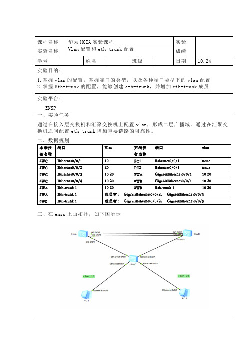
课程名称华为HCIA实验课程实验成绩实验名称Vlan配置和eth-trunk配置学号姓名班级日期10.24实验目的:1.掌握vlan的配置,掌握端口的类型,以及各种端口类型下的vlan配置2.掌握Eth-trunk的配置,能够创建eth-trunk,并增加eth-trunk成员实验平台:ENSP一、实验任务通过在接入层交换机和汇聚交换机上配置vlan,形成二层广播域。
通过在汇聚交换机之间配置eth-trunk增加重要链路的可靠性。
二、数据规划本端设备名称端口Vlan 对端设备名称端口vlanSWC Ethernet0/0/1 10 PC1 Ethernet0/0/1 none SWC Ethernet0/0/2 20 PC2 Ethernet0/0/1 none SWC Ethernet0/0/3 10 20 SWA GigabitEthernet0/0/1 10 20 SWC Ethernet0/0/4 10 20 SWB GigabitEthernet0/0/1 10 20 SWA Eth-trunk 1 10 20 SWB Eth-trunk 1 10 20 SWA Eth-trunk 1 成员有:GigabitEthernet0/0/2、GigabitEthernet0/0/3 SWB Eth-trunk 1 成员有:GigabitEthernet0/0/2、GigabitEthernet0/0/3三、在ensp上画拓扑,如下图所示[SWB]vlan batch 10 20[SWB]interface GigabitEthernet 0/0/1[SWB-GigabitEthernet0/0/1]port link-type trunk[SWB-GigabitEthernet0/0/1]port trunk allow-pass vlan 10 20 [SWB-GigabitEthernet0/0/1]quit[SWB]interface Eth-Trunk 1[SWB-Eth-Trunk1]port link-type trunk[SWB-Eth-Trunk1]port trunk allow-pass vlan 10 20[SWB-Eth-Trunk1]quit[SWB] interface GigabitEthernet 0/0/2[SWB-GigabitEthernet0/0/2]eth-trunk 1[SWB-GigabitEthernet0/0/2]quit[SWB] interface GigabitEthernet 0/0/3[SWB-GigabitEthernet0/0/3]eth-trunk 1[SWB-GigabitEthernet0/0/3]quit[SWB]quit<SWB>save2,通过配置生成了虚拟局域网,并且有两条两路捆绑生成了一条链路。
VLAN的网络配置

谈到VLAN,或许许多人都觉得非常神秘,甚至包括一些网管人员。
其实有关VLAN的技术标准IEEE 802.1Q 早在1999年6月份就由IEEE委员正式公布实施了,而且最早的VLNA技术早在1996年Cisco〔思科〕公司就提出了。
随着几年来的开展,VLAN技术得到广泛的支持,在大大小小的企业网络中广泛应用,成为当前最为热门的一种以太局域网技术。
本篇就要为大家介绍交换机的一个最常见技术应用--VLAN技术,并针对中、小局域网VLAN的网络配置以实例的方式向大家简单介绍其配置方法。
一、VLAN根底VLAN〔Virtual Local Area Network〕的中文名为"虚拟局域网",注意不是"VPN"〔虚拟专用网〕。
VLAN 是一种将局域网设备从逻辑上划分〔注意,不是从物理上划分〕成一个个网段,从而实现虚拟工作组的新兴数据交换技术。
这一新兴技术主要应用于交换机和路由器中,但主流应用还是在交换机之中。
但又不是所有交换机都具有此功能,只有VLAN协议的第三层以上交换机才具有此功能,这一点可以查看相应交换机的说明书即可得知。
IEEE于1999年公布了用以标准化VLAN实现方案的802.1Q协议标准草案。
VLAN技术的出现,使得管理员根据实际应用需求,把同一物理局域网内的不同用户逻辑地划分成不同的播送域,每一个VLAN都包含一组有着一样需求的计算机工作站,与物理上形成的LAN有着一样的属性。
由于它是从逻辑上划分,而不是从物理上划分,所以同一个VLAN内的各个工作站没有限制在同一个物理*围中,即这些工作站可以在不同物理LAN网段。
由VLAN的特点可知,一个VLAN内部的播送和单播流量都不会转发到其他VLAN中,从而有助于控制流量、减少设备投资、简化网络管理、提高网络的平安性。
交换技术的开展,也加快了新的交换技术〔VLAN〕的应用速度。
通过将企业网络划分为虚拟网络VLAN 网段,可以强化网络管理和网络平安,控制不必要的数据播送。
思科交换机常用命令

Cisco交换机命令大总结cisco交换机还是比较常用的,于是我研究了一下Cisco交换机命令的大总结,在这里拿出来和大家分享一下,希望对大家有用。
我所针对的都是Cisco的设备而言的,华为的可以跟据手册来查,配置都是差不多的,这里华子就不多写华为的设备了,了解的也不是很多。
Cisco交换机命令之使用Telnet远程式管理switch(config)#interface vlan 1 进入vlan 1switch(config-if)#ip address 设置IP地址switch(config-if)#ip default-gateway 设置默认网关switch(config)#line vty 0 4 进入虚拟终端switch(config-line)#login 允许登录switch(config-line)#password xx 设置登录口令switch#exit 返回命令Cisco交换机命令之控制台口令switch(config)#line console 0 进入控制台口switch(config-line)#login 允许登录switch(config-line)#password xx 设置登录口令switch#exit 返回命令Cisco交换机命令之基本接口配置switch(config)#interface f0/1 进入f0/1接口switch(config-if)#duplex full 配置全双工模式switch(config-if)#speed 100 配置速率switch(config-if)#description to ***** 接口描述switch(config)#ip domain-name ***.com 设置或名服务器switch(config)#mac-address-table aging-time 设置mac表超时时间switch#write 保存配置信息switch#copy running-config startup-config 保存当前配置nvramswitch#erase startup-config 清除配置文件Cisco交换机命令之交换机VLAN设置:switch#vlan database 进入VLAN设置switch(vlan)#vlan 2 建VLAN 2switch(vlan)#name 名字建VLAN 2的名称switch(vlan)#no vlan 2 删vlan 2注:删除vlan时原属于此vlan的端口处于非激活状态,直到重新分配为止。
02 二层技术-以太网交换配置指导-VLAN配置

目录1 VLAN配置 ·········································································································································· 1-11.1 VLAN简介·········································································································································· 1-11.1.1 VLAN概述 ······························································································································· 1-11.1.2 VLAN原理 ······························································································································· 1-21.1.3 VLAN划分 ······························································································································· 1-31.1.4 协议规范 ································································································································· 1-31.2 配置VLAN基本属性 ··························································································································· 1-31.3 配置VLAN接口基本属性···················································································································· 1-41.3.1 VLAN接口简介························································································································ 1-41.3.2 配置VLAN接口基本属性 ········································································································· 1-41.4 配置基于端口的VLAN ······················································································································· 1-51.4.1 基于端口的VLAN简介 ············································································································· 1-51.4.2 配置基于Access端口的VLAN ································································································· 1-61.4.3 配置基于Trunk端口的VLAN ···································································································· 1-71.4.4 配置基于Hybrid端口的VLAN ·································································································· 1-81.4.5 基于端口的VLAN典型配置举例 ······························································································ 1-91.5 配置基于MAC的VLAN ····················································································································· 1-111.5.1 基于MAC的VLAN简介 ·········································································································· 1-111.5.2 配置基于MAC的VLAN ·········································································································· 1-131.5.3 基于MAC的VLAN典型配置举例···························································································· 1-151.6 VLAN显示和维护····························································································································· 1-171 VLAN配置1.1 VLAN简介1.1.1 VLAN概述以太网是一种基于CSMA/CD(Carrier Sense Multiple Access/Collision Detect,载波侦听多路访问/冲突检测)的共享通讯介质的数据网络通讯技术,当主机数目较多时会导致冲突严重、广播泛滥、性能显著下降甚至使网络不可用等问题。
学会VLAN的基础配置
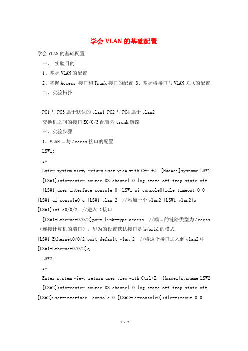
学会VLAN的基础配置学会VLAN的基础配置一、实验目的1、掌握VLAN的配置2、掌握Access 接口和Trunk接口的配置3、掌握将接口与VLAN关联的配置二、实验拓扑PC1与PC3属于默认的vlan1 PC2与PC4属于vlan2交换机之间的接口E0/0/3配置为trunk链路三、实验步骤1、VLAN口与Access接口的配置LSW1:syEnter system view, return user view with Ctrl+Z. [Huawei]sysname LSW1 [LSW1]info-center source DS channel 0 log state off trap state off [LSW1]user-interface console 0 [LSW1-ui-console0]idle-timeout 0 0 [LSW1-ui-console0]q [LSW1]vlan 2 //添加一个vlan2 [LSW1-vlan2]q [LSW1]int e0/0/2 //进入2接口[LSW1-Ethernet0/0/2]port link-type access //端口的链路类型为Access (连接计算机的端口),华为的设置默认接口是hybrid的模式[LSW1-Ethernet0/0/2]port default vlan 2 //将这个接口加入到vlan2中[LSW1-Ethernet0/0/2]qLSW2:syEnter system view, return user view with Ctrl+Z. [Huawei]sysname LSW2 [LSW2]info-center source DS channel 0 log state off trap state off [LSW2]user-interface console 0 [LSW2-ui-console0]idle-timeout 0 0[LSW2-ui-console0]q [LSW2]vlan 2 //添加一个vlan2[LSW2-vlan2]int e0/0/2[LSW2-Ethernet0/0/2]port link-type access //端口的链路类型为Access [LSW2-Ethernet0/0/2]port default vlan 2 //将这个接口加入到vlan2中[LSW2-Ethernet0/0/2]q? 在各交换机上用dis vlan这个命令来查看上面的e0/0/2接口是否已经加入到vlan2中 [LSW1]dis vlanThe total number of vlans is : 2--------------------------------------------------------------------------------U: Up; D: Down; TG: Tagged; UT: Untagged; MP: Vlan-mapping; ST: Vlan-stacking; #:ProtocolTransparent-vlan; *: Management-vlan;-------------------------------------------------------------------------------- VID Type Ports--------------------------------------------------------------------------------1 common UT:Eth0/0/1(U) Eth0/0/3(U) Eth0/0/4(D)Eth0/0/5(D)Eth0/0/6(D) Eth0/0/7(D) Eth0/0/8(D)Eth0/0/9(D)Eth0/0/10(D) Eth0/0/11(D) Eth0/0/12(D)Eth0/0/13(D)Eth0/0/14(D) Eth0/0/15(D) Eth0/0/16(D)Eth0/0/17(D)Eth0/0/21(D)Eth0/0/22(D) GE0/0/1(D) GE0/0/2(D) 2 common UT:Eth0/0/2(U) //已经属于vlan2了 VID StatusProperty MAC-LRN Statistics Description--------------------------------------------------------------------------------1 enable default enable disable VLAN 00012 enable default enable disable VLAN 0002[LSW2]dis vlanThe total number of vlans is : 2--------------------------------------------------------------------------------U: Up; D: Down; TG: Tagged; UT: Untagged; MP:Vlan-mapping; ST: Vlan-stacking; #:ProtocolTransparent-vlan; *: Management-vlan;-------------------------------------------------------------------------------- VID Type Ports--------------------------------------------------------------------------------1 common UT:Eth0/0/1(U) Eth0/0/3(U) Eth0/0/4(D)Eth0/0/5(D)Eth0/0/6(D) Eth0/0/7(D) Eth0/0/8(D)Eth0/0/9(D)Eth0/0/10(D) Eth0/0/11(D) Eth0/0/12(D)Eth0/0/13(D)Eth0/0/17(D)Eth0/0/18(D) Eth0/0/19(D) Eth0/0/20(D)Eth0/0/21(D)Eth0/0/22(D) GE0/0/1(D) GE0/0/2(D) 2 common UT:Eth0/0/2(U) //已经属于vlan2了 VID StatusProperty MAC-LRN Statistics Description--------------------------------------------------------------------------------1 enable default enable disable VLAN 00012 enable default enable disable VLAN 00022、Trunk接口的配置1上面的拓扑图和配置命令来看,交换机之间的e0/0/3接口默认是属于vlan1◇的,因此只能是PC1与PC3这两台主机是可以拼通的,要想实现PC2与PC4之间的互通,则需要将交换机之间相连的接口配置为trunk,命令如下:[LSW1]int e0/0/3 //进接口 [LSW1-Ethernet0/0/3]portlink-type trunk //接口链路类型为trunk [LSW1-Ethernet0/0/3]porttrunk allow-pass vlan all //允许所有的vlan通过,华为的设备默认是不允许任何vlan通过的,除了缺省的vlan1[LSW2]int e0/0/3 //进接口 [LSW2-Ethernet0/0/3]portlink-type trunk //接口链路类型为trunk [LSW2-Ethernet0/0/3]porttrunk allow-pass vlan all /允许所有的vlan通过2在各交换机上查看vlan的信息◇[LSW1]dis vlanThe total number of vlans is : 2--------------------------------------------------------------------------------U: Up; D: Down; TG: Tagged; UT: Untagged; MP:Vlan-mapping; ST: Vlan-stacking; #:ProtocolTransparent-vlan; *: Management-vlan;-------------------------------------------------------------------------------- VID Type Ports--------------------------------------------------------------------------------1 common UT:Eth0/0/1(U) Eth0/0/3(U) Eth0/0/4(D)Eth0/0/5(D)Eth0/0/6(D) Eth0/0/7(D) Eth0/0/8(D)Eth0/0/9(D)Eth0/0/10(D) Eth0/0/11(D) Eth0/0/12(D)Eth0/0/13(D)Eth0/0/14(D) Eth0/0/15(D) Eth0/0/16(D)Eth0/0/17(D)Eth0/0/18(D) Eth0/0/19(D) Eth0/0/20(D)Eth0/0/21(D)Eth0/0/22(D) GE0/0/1(D) GE0/0/2(D) 2 common UT:Eth0/0/2(U) TG:Eth0/0/3(U)VID Status Property MAC-LRN Statistics Description--------------------------------------------------------------------------------1 enable default enable disable VLAN 00012 enable default enable disable VLAN 0002[LSW2]dis vlanThe total number of vlans is : 2--------------------------------------------------------------------------------U: Up; D: Down; TG: Tagged; UT: Untagged; MP:Vlan-mapping; ST: Vlan-stacking; #:ProtocolTransparent-vlan; *: Management-vlan;-------------------------------------------------------------------------------- VID Type Ports--------------------------------------------------------------------------------1 common UT:Eth0/0/1(U) Eth0/0/3(U) Eth0/0/4(D)Eth0/0/5(D)Eth0/0/6(D) Eth0/0/7(D) Eth0/0/8(D)Eth0/0/9(D)Eth0/0/10(D) Eth0/0/11(D) Eth0/0/12(D)Eth0/0/13(D)Eth0/0/14(D) Eth0/0/15(D) Eth0/0/16(D)Eth0/0/17(D)Eth0/0/18(D) Eth0/0/19(D) Eth0/0/20(D)Eth0/0/21(D)Eth0/0/22(D) GE0/0/1(D) GE0/0/2(D) 2 common UT:Eth0/0/2(U) TG:Eth0/0/3(U)VID Status Property MAC-LRN Statistics Description--------------------------------------------------------------------------------1 enable default enable disable VLAN 00012 enable default enable disable VLAN 00023、接口与VLAN关联的配置1 当交换机需要与网络层的设备通信时,可以在交换机上创建基于VLAN的◇逻辑接口,即VLANIF接口。
vlan间路由的trunk接口的配置方法
vlan间路由的trunk接口的配置方法VLAN间路由是一种通过Trunk接口实现不同VLAN之间通信的方法。
在本文中,我们将详细介绍如何配置Trunk接口以实现VLAN间路由。
我们需要了解Trunk接口的概念。
Trunk接口是一种可以传输多个VLAN数据的物理或逻辑接口。
它允许在交换机之间传输来自不同VLAN的数据包,从而实现VLAN间路由。
在配置Trunk接口之前,我们需要先创建VLAN并为其分配相应的接口。
假设我们有三个VLAN,分别为VLAN10、VLAN20和VLAN30。
现在我们将为这三个VLAN创建Trunk接口并配置路由。
1. 配置Trunk接口我们需要进入交换机的配置模式。
可以通过命令"enable"进入特权模式,然后再输入"configure terminal"进入全局配置模式。
接下来,我们需要找到Trunk接口的接口编号。
可以使用命令"show interfaces"查看所有接口的状态和编号。
一旦找到了Trunk接口的编号,我们可以使用以下命令来配置Trunk接口:```interface interface编号switchport mode trunk```其中,"interface编号"是我们找到的Trunk接口的编号。
这个命令将接口配置为Trunk模式,使其能够传输多个VLAN的数据。
2. 配置VLAN间路由接下来,我们需要配置VLAN间的路由。
在本例中,我们将使用交换机自带的路由功能来实现。
我们需要创建VLAN接口并将其与相应的VLAN关联。
可以使用以下命令来完成:```interface vlan vlan编号```其中,"vlan编号"是我们要创建的VLAN的编号。
使用这个命令后,我们进入了VLAN接口的配置模式。
然后,我们需要为VLAN接口配置IP地址。
可以使用以下命令来完成:```ip address IP地址子网掩码```其中,"IP地址"是我们要为VLAN接口配置的IP地址,"子网掩码"是相应的子网掩码。
vlan基本命令配置trunk链路配置

vlan基本命令配置trunk链路配置<a target="_blank" href="///wpa/qunwpa?idkey=8a8ad9b8f03685df6bde84370578b288f2a615862defa4f1313567ee78a10858"><img border="0"src="///wpa/images/group.png" alt="IT资料群" title="IT资料群"></a>1 案例1:vlan基本命令1.1 问题1)在交换机上创建vlan10,修改名称为web并查看vlan配置2)删除vlan10,查看vlan配置3)创建vlan20,将端⼝f0/1加⼊此vlan,查看vlan配置4)将f0/1从vlan20中删除,查看vlan配置1.2 步骤实现此案例需要按照如下步骤进⾏步骤⼀:在交换机上创建vlan10,修改名称为web并查看vlan配置1. Switch>enable2. Switch#configure terminal3. Switch(config)#vlan 104. Switch(config-vlan)#name web5. Switch(config-vlan)#end6. Switch#show vlan brief步骤⼆:删除vlan10,查看vlan配置1. Switch#configure terminal2. Switch(config)#no vlan 103. Switch(config)#end4. Switch#show vlan brief步骤三:创建vlan20,将f0/1端⼝加⼊此vlan,查看vlan配置1. Switch#configure terminal2. Switch(config)#vlan 203. Switch(config-vlan)#exit4. Switch(config)#interface fastethernet 0/15. Switch(config-if)#switchport access vlan 206. Switch(config)#end7. Switch#show vlan brief步骤四:将f0/1端⼝从vlan20中删除,查看vlan配置1. Switch#configure terminal2. Switch(config)#interface fastethernet 0/13. Switch(config-if)#no switchport access vlan 204. Switch(config)#end5. Switch#show vlan brief2 2 案例2:vlan基本配置2.1 问题在交换机上创建以下vlan,按照拓扑图-1将端⼝加⼊到指定的vlan并配置服务器IP地址,实现通vlan主机的通信图-12.2 步骤1. Switch>enable2. Switch#configure terminal3. Switch(config)#vlan 24. Switch(config-vlan)#vlan 35. Switch(config-vlan)#exit6. Switch(config)#interface range fastEthernet 0/3-47. Switch(config-if-range)#switchport access vlan 28. Switch(config-vlan)#exit9. Switch(config)#interface range fastEthernet 0/5-610. Switch(config-if-range)#switchport access vlan 311. Switch#show vlan brief3 3 案例3:跨交换机同vlan通信3.1 问题通过配置交换机实现图-2中的vlan主机互通图-23.2 步骤S1配置1. Switch#configure terminal2. Switch(config)#interface fastethernet 0/73. Switch(config-if)#switchport access vlan 3S2配置1. Switch>enable2. Switch#configure terminal3. Switch(config)#vlan 34. Switch(config-vlan)#exit5. Switch(config)#interface range fastEthernet 0/5-76. Switch(config-if-range)#switchport access vlan 34 4 案例4:trunk链路配置4.1 问题如图-3所⽰1)配置s1的f0/1端⼝为trunk模式,分别查看两台交换机f0/1端⼝的状态2)恢复s1的f0/1端⼝为默认模式,分别查看两台交换机f0/1端⼝的状态图-34.2 步骤配置s1的f0/1⼝为trunk模式,分别查看两台交换机f0/1端⼝状态1. Switch>enable2. Switch#configure terminal3. Switch(config)#interface fastEthernet 0/14. Switch(config-if)#switchport mode trunk5. Switch(config-if)#end6. Switch#show interfaces fastEthernet 0/1 switchport恢复s1的f0/1⼝为默认模式,分别查看两台交换机f0/1端⼝状态1. Switch#configure terminal2. Switch(config)#interface fastEthernet 0/13. Switch(config-if)#no switchport mode trunk4. Switch#show interfaces fastEthernet 0/1 switchport5 5 案例5:多vlan跨交换机通信5.1 问题通过配置实现跨交换机的同vlan通信,如图-4所⽰图-45.2 步骤注:以下配置需要在练习3的基础上完成S1配置1. Switch>enable2. Switch#configure terminal3. Switch(config)#interface fastEthernet 0/74. Switch(config-if)#switchport mode trunkS2配置1. Switch>enable2. Switch#configure terminal3. Switch(config)#vlan 24. Switch(config-vlan)#exit5. Switch(config)#interface range fastEthernet 0/3-46. Switch(config-if-range)#switchport access vlan 27. Switch(config-if-range)#exit8. Switch(config)#interface fastEthernet 0/79. Switch(config-if)#switchport mode trunk6 6 案例6:以太⽹通道6.1 问题参照图-5将交换机的f0/7-f0/9端⼝配置为以太⽹通道图-56.2 步骤S1配置1. Switch>enable2. Switch#configure terminal3. Switch(config)#interface range fastEthernet 0/7-94. Switch(config-if-range)#channel-group 1 mode on5. Switch(config-if-range)#end6. Switch#show etherchannel summaryS2配置1. Switch>enable2. Switch#configure terminal3. Switch(config)#interface range fastEthernet 0/7-94. Switch(config-if-range)#channel-group 1 mode on5. Switch(config-if-range)#end6. Switch#show etherchannel summary。
实验四--VLAN配置实验
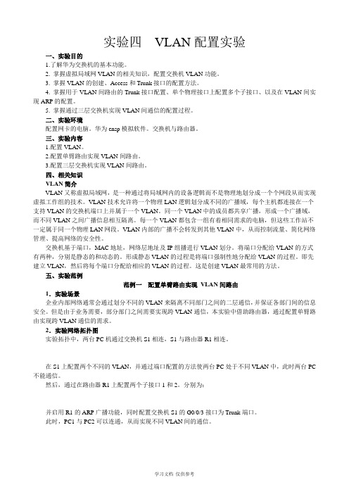
实验四VLAN配置实验一、实验目的1.了解华为交换机的基本功能。
2. 掌握虚拟局域网VLAN的相关知识,配置交换机VLAN功能。
3. 掌握VLAN的创建、Access和Trunk接口的配置方法。
4. 掌握用于VLAN间路由的Trunk接口配置、单个物理接口上配置多个子接口、以及在VLAN间实现ARP的配置。
5. 掌握通过三层交换机实现VLAN间通信的配置过程。
二、实验环境配置网卡的电脑。
华为ensp模拟软件。
交换机与路由器。
三、实验内容1.配置VLAN。
2.配置单臂路由实现VLAN间路由。
3.配置三层交换机实现VLAN间路由。
四、相关知识VLAN简介VLAN又称虚拟局域网,是一种通过将局域网内的设备逻辑而不是物理地划分成一个个网段从而实现虚拟工作组的技术。
VLAN技术允许将一个物理LAN逻辑划分成不同的广播域,每个主机都连接在一个支持VLAN的交换机端口上并属于一个VLAN。
同一个VLAN中的成员都共享广播,形成一个广播域,而不同VLAN之间广播信息相互隔离。
每一个VLAN都包含一组有着相同需求的电脑,但这些工作站不一定属于同一个物理LAN网段。
VLAN内部的广播不会转发到其他VLAN中,从而控制流量、简化网络管理、提高网络的安全性。
交换机基于端口,MAC地址,网络层地址及IP组播进行VLAN划分。
将端口分配给VLAN的方式有两种,分别是静态的和动态的。
形成静态VLAN的过程是将端口强制性地分配给VLAN的过程。
即先建立VLAN,然后将每个端口分配给相应的VLAN的过程。
这是创建VLAN最常用的方法。
五、实验范例范例一配置单臂路由实现VLAN间路由1.实验场景企业内部网络通常会通过划分不同的VLAN来隔离不同部门之间的二层通信,并保证各部门间的信息安全。
但是由于业务需要,部分部门之间需要实现跨VLAN通信,本实验中借助路由器,通过配置单臂路由实现跨VLAN通信的需求。
2.实验网络拓扑图实验拓扑中,两台PC机通过交换机S1相连,S1与路由器R1相连。
VLAN及Trunk实验

VLAN及Trunk实验一基本VLAN试验实验拓扑:实验目的:掌握VLAN基本配置掌握静态接口VLAN划分实验需求:在交换机switch上面创建两个VLAN,vlan2和vlan3,vlan名称分别为HR、ENG将主机PC1、PC2分别划入两个VLAN中实验步骤:步骤一:创建VLAN2与VLAN3Switch#conf tSwitch(config)#vlan 2Switch(config-vlan)#name HRSwitch(config-vlan)#exitSwitch(config)#vlan 3Switch(config-vlan)#name ENG步骤二:将与两台PC连接的两个接口分别划入两个VLAN中Switch(config)#int fa0/1Switch(config-if)#switchport mode access//将接口模式设置为接入接口Switch(config-if)#switchport access vlan 2//将接口划入指定VLAN中Switch(config-if)#endSwitch(config)#int fa0/2Switch(config-if)#switchport mode accessSwitch(config-if)#switchport access vlan 3Switch(config-if)#end步骤三:使用show vlan命令查看实验结果,在PC1以及PC2上使用ping命令查看连通性。
二Vlan Trunk 实验实验拓扑:实验目的:掌握Trunk的基本配置实验需求:在交换机SW1与SW2上创建VLAN2,并将两个交换机之间的链路设置成trunk 链路,使vlan数据能够跨越交换机实验步骤:步骤一:在交换机SW1、SW2上创建VLAN2,并将其与主机连接的接口划入对应VLAN中SW1#conf tSW1(config)#vlan 2SW1(config-vlan)#name HRSW1(config-vlan)#exitSW1(config)#int fa0/1SW1(config-if)#switchport mode accessSW1(config-if)#switchport access vlan 2SW2#conf tSW2(config)#vlan 2SW2(config-vlan)#name HRSW2(config-vlan)#exitSW2(config)#int fa0/2SW2(config-if)#switchport mode accessSW2(config-if)#switchport access vlan 2步骤二:将两个交换机之间的链路配置为Trunk链路SW1(config)#int fa0/20SW1(config-if)#switchport trunk encapsulation dot1q//如果交换机支持多种trunk封装,则必须先指定所使用的封装。
