LED光学测试系统IS机操作说明书
机器视觉数字式LED光源控制器使用说明书

机器视觉数字式LED光源控制器使用说明书安全事项1.在第一次安装和使用本产品之前,请您务必先仔细阅读本使用说明书。
2.使用本产品之前,请确认输出规格(电压、电流、端子定义)与所用LED 光源的规格是否匹配。
3.请确保输入交流电源的地线可靠接地,以避免可能导致的财产损失或人身伤害。
4.连接光源线缆时务必断开输入电源。
通电前请仔细检查输入输出线缆是否连接正确,确保本产品可靠工作。
5.请勿在易燃易爆的环境下操作,请保持产品表面的清洁和干燥。
6.如果发现以下任何一种情况,或者对产品的安全有所顾虑,应停止使用本产品并断开它与电源及其他线缆的连接,以减低造成人身伤害和财产损失的风险。
并请及时向供应商获取技术支持和售后服务。
6.1电源线、电源插座、端子、开关、按键等损坏;6.2有过热、烟雾、火花或者起火现象;6.3产品发出爆裂声或者有异味;6.4产品内部进水;6.5产品由高处跌落或者外壳有损伤;6.6按照使用说明书操作时产品不能正常工作。
7.除非得到本公司的许可和技术支持,否则请勿尝试自行维修产品。
产品简介本产品是为驱动机器视觉LED光源而设计的可编程远程数字控制器。
其具有以下几种功能:256级亮度调节功能,计算机通信控制功能(RS232接口),触发功能(软件触发和硬件触发),自动保存亮度设置等级,前面板带有数字显示,可手动调节亮度并设有防止误操作的解锁键。
通过RS232接口将光源控制器与计算机相连,即可通过软件远程对LED光源实现256级亮度调节功能,控制LED 光源的亮灭,也可通过外部触发信号(高、低电平信号)以硬件方式远程控制LED光源的亮灭,这种触发工作方式可极大地延长LED光源的使用寿命,尤其适用于复杂高端的机器视觉设备使用。
1.技术参数1.1 机械参数1.1.1外壳材料:钢板、前面板贴彩色复合材料1.1.2外壳颜色:黑色1.1.3外形尺寸:168*131*90(L*W*H)1.1.4重 量:1.2 电气参数1.2.1通 道 数:41.2.2输入电压:100-240VAC ~50/60Hz1.2.3输出电压:DC24V1.2.4输出电流:四个通道同时满载输出:第一、二通道最大电流1000mA,第三、四通道最大电流500mA。
LED测试系统使用说明

陈青松 2011-08-17
系统主界面
工具栏
点击主界面工具栏系统登录按钮,输入用户 名和密码,管理员账号密码均为admin,以管 理员身份登录后会多出系统校正面板,可以 进行光谱仪和电路板基本参数的校正 复位后将清除所有测试数据,计数清零,恢复 到系统初始状态
在主菜单文件子菜单里,可以将当前设置参数 另存为其它文件名,然后通过载入设置重新 载入到系统中
led光电综合测试系统介绍陈青松20110817工具栏点击主界面工具栏系统登录按钮输入用户名和密码管理员账号密码均为admin以管理员身份登录后会多出系统校正面板可以进行光谱仪和电路板基本参数的校正复位后将清除所有测试数据计数清零恢复到系统初始状态在主菜单文件子菜单里可以将当前设置参数另存为其它文件名然后通过载入设置重新载入到系统中工具栏保存当前所有设置窗口标题栏会显示当前配置文件名自动运行按钮按下后系统进入自动运行状态此时系统接收到plc的sot信号后开始测试测试完毕后将bin号和eot信号发送到plc
系统规范 电性测试项目及时间: 电性测试项目:极性POL、反向漏电IR、反 向电压VR、开启电压VFin、正向电流IF、正 向电压VF、亮度IV 典型测试时间: 30ms (单晶,POL、IR、VF、IV) 90ms (三晶,POL、IR、VF、IV)
系统规范 光学测试项目及时间: 光学测试项目:色坐标CIE_xy、主波长λd 、 色纯度PUR、峰值波长λp、色温CCT、光通量 LM、显色指数CRI、半高宽FWHM、色容差 SDCM 最小测试时间 * 10ms
± 0.002 ± 0.35 nm ± 0.5 nm
工具栏
连续测试按钮按下后,系统将进入单灯连续测
试状态,连续测试的相关设置将在后面的单灯测 试统计界面进行介绍。和单步测试一样,系统不 接收SOT信号,也不发送BIN号及EOT信号。
LED光谱分析系统测试仪操作规程
1.LED光谱测试仪器每一次使用前或长期停用后再次使用,必须进行仪器校准和通电30分钟后进入稳定状态后方可测试。
3.室内湿度不能超过额定湿度,以免影响灯珠测试参数的准确性。
4.禁止用手直接触摸灯珠,要带上防静电手套、穿上防静电鞋、防静电衣。
5.经常保持设备的清洁工作。
6、LED最大正向电压:15W : 25V、1W / 3W / 5W : 5V;脉冲宽度或预热点灯:小于350MA,时间设为500MS;大于350MA时间设为25MS,具体设置参考厂家灯珠参数规格书;积分时间:手动填写灯珠测试积分时间,然后调整脉冲宽度;看所测试IP数据要求在50%--90%之间;光度量程档位:自动。
6.定期检查各设备之间的连接线是否良好。
3、打开整套仪Βιβλιοθήκη 电源开关,让仪器通电30分钟后进入稳定状态。打开LED测试软件,选择测量模式,当使用LED300E电源时,一般选择脉冲测量模式,当使用WY精密数显直流稳压电源时,一般选择常规测量模式。
4、校正仪器,以保证数据的准确性(用标准灯作为校正光源)。
5、参数的设置:LED测试电流:按所测灯珠的参数要求设定。
7、测试:先建立一个新文档,按灯珠测试相应标准设置灯珠参数,然后按F2进入快速测试状态,把LED正确装在夹具上(注意方向),按F3进行测试。每测试一个LED重复此操作。
8、查看测试数据判断LED是否合格,通常对照正向电压、光通亮、主波长、相关色温是否符合检验标准。
9、测试完毕后按厂家不同,分类保存灯珠参数文档;然后关闭主机电源开关、高精度快速光谱辐射计开关、LED300E可编程电源开关、显示器等以及总闸开关。
广州市雅江光电设备有限公司
章节编号
LED灯具测试常用仪器仪表使用方法
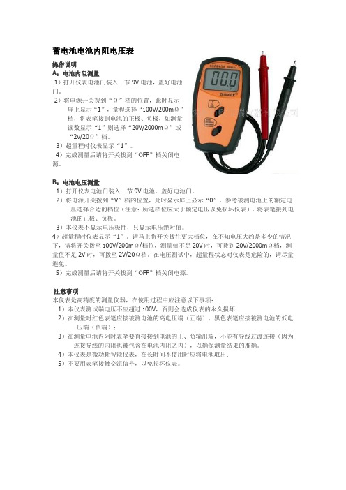
蓄电池电池内阻电压表操作说明A:电池内阻测量1)打开仪表电池门装入一节9V电池,盖好电池门。
2)将电源开关拨到“Ω”档的位置,此时显示屏上显示“1”,量程选择“100V/200mΩ”档,将表笔接到电池的正极、负极,如测量读数显示“1”则选择“20V/2000mΩ”或“2v/20Ω”档。
3)超量程时仪表显示“1”。
4)完成测量后请将开关拨到“OFF”档关闭电源。
B:电池电压测量1)打开仪表电池门装入一节9V电池,盖好电池门。
2)将电源开关拨到“V”档的位置,此时显示屏上显示“0”,参考被测电池上的额定电压选择合适的档位(注意:所选档位应大于额定电压以免损坏仪表),将表笔接到电池的正极、负极。
3)本仪表不显示电压极性,只显示电压绝对值。
4)超量程时仪表显示“1”。
请马上将开关拨往更大档位,在不知电压大约是多少的情况下,请将开关拨至100V/200mΩ/档位,测量值不足20V时,可拨到20V/2000mΩ档,测量值不足2V时,可拨至2V/20Ω档。
在电压测试中,超量程状态对仪表是危险的,请尽量避免。
5)完成测量后请将开关拨到“OFF”档关闭电源。
注意事项本仪表是高精度的测量仪器,在使用过程中应注意以下事项:1)本仪表测试端电压不应超过100V,否则会造成仪表的永久损坏;2)在测量时红色表笔应接被测电池的高电压端(正端),黑色表笔应接被测电池的低电压端(负端);3)在测量电池内阻时表笔要直接接到电池的正、负输出端,不能有导线过渡连接(因为连接导线的内阻也被包含在电池内阻之内),以确保测量结果的准确。
4)本仪表是微功耗智能仪表,在长时间不使用时应将电池取出;5)不要用表笔接触交流信号,以免损坏仪表。
数字式照度计一、各部名称和功能:◆液晶显示器:32/1位液晶显示器,最大读值1999,可显示测量范围。
◇TES-1332-"LUX","H","20,000","×10"(读值乘以10),"×100"(读值乘以100)和"BT"◆读值锁定开关:按HOLD开关一次,出现"H"符号,即能恒久锁LCD之数值,不能做照度测量;再按一次HOLD开关,取消HOLD功能并重新测量照度。
3B SCIENTIFIC 4 LED 波长测量仪手册说明书

3B SCIENTIFIC ® PHYSICS1Bedienungsanleitung09/15 THL/ALF1 Feststehender Zeiger2 Analysator3 Sichtöffnung4Messkammer mit Messzy-linder und Polarisator5 LED-Umschalter6 Steckernetzgerät∙Direktes Hineinblicken in die geöffnete Mess-kammer auf die hell leuchtenden LED’s vermei -den.∙ Das Gerät nur mit dem zugehörigen Ste-ckernetzgerät 12V DC betreiben.∙Bei sichtbaren äußeren Schäden des Netz-gerätes oder des Polarimeters istein weite-rer Betrieb unzulässig.Das Polarimeter mit 4 LED dient zur Bestim-mung des Drehwinkels und der Drehrichtung von polarisiertem Licht durch eine optisch aktive Substanz in Abhängigkeit der Wellenlänge, der Probendicke und der Probenkonzentration.Das Polarimeter ist mit einer Beleuchtungsein-richtung aus vier monochromatischen Leuchtdi-oden bestückt. Das von der eingeschalteten Leuchtdiode ausgehende Licht wird von einem Polarisator, der sich unter der Aufnahme für den Messzylinder in der Messkammer befindet, line-ar polarisiert.Im Analysator befindet sich ein zweiter Polarisa-∙Lichtwellenlänge durch Verschieben des23B Scientific GmbH ▪ Rudorffweg 8 ▪ 21031 Hamburg ▪ Deutschland ▪ Technische Änderungen vorbehalten © Copyright 2015 3B Scientific GmbHHinweis:100 ml Flüssigkeit im Messzylinder entsprechen einer Schichtdicke von 1,9 dm, 75 ml – 1,43 dm, 50 ml – 0,96 dm und 25 ml – 0,44 dm.∙ Drehwinkel für die verschiedenen LEDsmessen.∙ Im nächsten Schritt bei gleicher Konzentrati-on Schichtdicke auf 1,43 dm (75 ml) verrin-gern und die Messung wiederholen.∙ Weitere Messungen mit Schichtdicken von0,96 dm (50 ml) und 0,44 dm (25 ml) durch-führen.∙ Anschließend Zuckerlösungen (20 g, 30 gund 40 g in 100 ml) herstellen und analog zur ersten Messreihe Drehwinkel messen. ∙ Werte in einer Tabelle erfassen und denDrehwinkel in Abhängigkeit der Konzentrati-on und der Schichtdicke für jede Farbe gra-fisch darstellen.6.2 Bestimmung des spezifischen Drehwin-kels von Saccharose Der spezifische Drehwinkel []α ist eine Stoff-konstante und ergibt sich aus folgender Glei-chung bei bekannter Wellenlänge des Lichts λ und Temperatur T :[]l c T ⋅α=αλ(1) α = gemessener Drehwinkelc = Konzentration c des gelösten Stoffes l = Schichtdicke der LösungLiteraturangaben beziehen sich meistens auf die gelbe Natrium D-Linie (λ = 589 nm) und eine Temperatur von 20 °C.∙ Zuckerlösung (50 g in 100 ml) herstellen.Dazu 50 g Zucker abwiegen, in ca. 60 cm 3 destilliertem Wasser auflösen und im Mess-zylinder auf 100 cm 3 auffüllen.∙ Schichtdicke abmessen und Messzylinder indie Messkammer einsetzen.∙ Drehwinkel bei gelbem Licht bestimmen.∙ Spezifischen Drehwinkel nach Gleichung 1errechnen und mit Literaturwert vergleichen.Literaturwerte für spezifische Drehwinkel []20D α Saccharose +66,5°, D-Glucose +52,7°, D-Fructose-92,4°. (Werte aus Aebi, Einführung in die prakti-sche Biochemie, Karger 1982)6.3 Inversion von SaccharoseMit Säure lässt sich Saccharose in D-Glucose und D-Fructose spalten, dabei werden beide Bestandteile in gleichen Maßen frei. Die Rechts-drehung wird geringer bis der Drehwinkel schließlich negativ wird. Diesen Vorgang nennt man Inversion. Das Glucose-Fructose-Gemisch heißt deshalb Invertzucker und ist z.B. ein Be-standteil von Kunsthonig.∙ Zuckerlösung (30 g in 100 ml) herstellen.Dazu 30 g Zucker abwiegen, in ca. 60 cm 3 destilliertem Wasser (50° C) auflösen.∙ Vorsichtig (Schutzbrille) 15 ml 25 %ige Salz-säure hinzufügen.∙ Lösung im Messzylinder auf 100 cm 3 auffül-len und in die Messkammer stellen.∙ Sofort eine Stoppuhr in Gang setzen undden Drehwinkel bestimmen.∙ In Abständen von 5 Minuten erneut denDrehwinkel messen und alle Messwerte in einer Tabelle notieren.∙ Nach 30 Minuten die Messreihe beendenund die Inversionskurve zeichnen.6.4 Konzentrationsmessung bei bekanntemspezifischen Drehwinkel am Beispiel Rohrzucker in Cola∙ Messzylinder mit 100 ml Cola befüllen.∙ Drehwinkel und Drehsinn mit Hilfe der gel-ben Diode bestimmen.∙ Zuckergehalt durch Umstellung der Glei-chung 1 errechnen.[]l c ⋅αα=⎥⎦⎤⎢⎣⎡3cm g (2)。
LED光电测试仪说明书
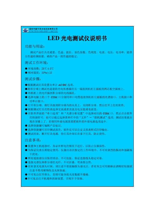
LED光电测试仪说明书功能与用途:测试产品灯具光通量、色温、波长、显色指数、色纯度、电流、电压、电功率,提供全性能检测依据。
确保产品一致性能的稳定。
测试工作环境:●环境指数:23℃±5℃●相对湿度:55%±25测试步骤:●根据测试灯具设置功率计AC/DC选项。
●将积分球上测试光通量的光电传感器的另一端接到机柜左面板的两芯航空插座上。
●将机柜上的光纤插到积分球的光线插孔。
●选择电脑上的三个COM口分别用串口电缆连接到机柜左面板的光谱接口、主机接口和功率计接口。
●打开积分球,将灯具接到积分球内的夹具上,关闭积分球。
然后打开上位机软件;●根据测试灯具的性质选择交流或者直流及电压值或电流值。
●在软件界面的“串口选项”和“光谱分析设置”中选择对应的COM口,然后点击软件的快捷即可,也可以通过选择菜单栏中的“文件”→“联机测试”选项,测试结果就出现在屏幕上了。
若使用外部电源需要把软件的外部电源选项选中。
●选择快捷键可编辑产品标识。
●选择快捷键可打印测试报告,软件还可以自定义报表样式打印输出。
●测试结束,断开灯具电源,待灯具冷却后在拿下灯具,防止烫伤。
注意事项:●装置和主机连接时,务必在断电的情况下进行,以防止仪器损伤。
●为保证仪表长期稳定使用,仪器应该在指定的工作环境中,不可有剧烈的振动和强磁场干扰处。
●所有连接部分应保持清洁、不可拉扯,保证连接线头稳定可靠。
●连接光谱仪和积分球的光纤,不可折叠,弯曲要自然。
●在卸拿光电探头时候,请注意不要接触探头感光区,若有灰尘可用棉棒沾酒精轻轻擦拭注意不得用硬物伤及光探表面。
●不可私自打开探头,否则可能导致光度数据不准确。
●不可私自打开机箱和拆卸装置,否则不予保修。
LS说明书
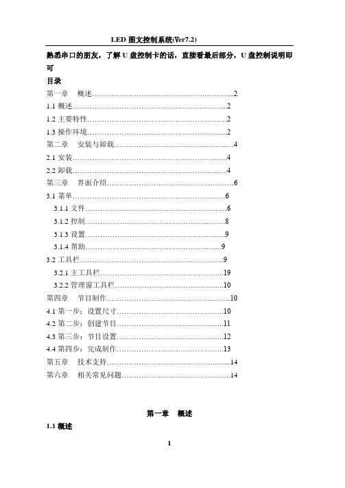
熟悉串口的朋友,了解U盘控制卡的话,直接看最后部分,U盘控制说明即可目录第一章概述 (2)1.1概述 (2)1.2主要特性 (2)1.3操作环境 (2)第二章安装与卸载 (4)2.1安装 (4)2.2卸载 (4)第三章界面介绍 (6)3.1菜单 (6)3.1.1文件 (6)3.1.2控制 (8)3.1.3设置 (9)3.1.4帮助 (9)3.2工具栏 (9)3.2.1主工具栏 (19)3.2.2管理窗工具栏 (10)第四章节目制作 (10)4.1第一步:设置尺寸 (10)4.2第二步:创建节目 (11)4.3第三步:节目设置 (12)4.4第四步:完成制作 (13)第五章技术支持 (14)第六章相关常见问题 (14)第一章概述1.1概述LED图文控制系统是由联胜电子科技公司为图文控制系统专业制作的集编辑、模拟和控制为一体的专业软件。
它不仅安全、稳定、实用而且便于各类人群的学习和使用。
由于其高可靠性和稳定性,它被广泛运用于各个领域。
本软件其根据人机交互原理设计使其结构合理、便于使用和维护,界面简洁而不单调,功能强大却不紊乱,处处显示出以人为本的特点。
最为重要的是它具有功能上的可扩展性。
1.2主要特性节目的播放是以页的方式进行的,页的数量根据LED条屏的尺寸的不同而各异。
其控制方式通常采用串口通讯,包括单机版的RS232以及服务器版的RS485网络通讯。
1.3操作环境操作系统:中/英文Windows/XP;硬件配置:CPU: 奔腾300MHz或以上内存:64M或以上第二章安装与卸载2.1 安装安装LED图文控制系统,可按照如下步骤进行:双击“setup”文件,在弹出的安装向导对话框中,系统显示界面:单击下一步,系统将自动进行安装。
)系统自动完装完毕后,会在您的电脑桌面上自动生成一个快捷方式图标双击该图标直接运行程序。
2.2卸载LED图文控制系统软件为您提供了一个自动卸载功能选择,以删除控制系统的所有文件、程序组以及快捷方式等。
机器视觉数字式LED光源控制器使用说明书
机器视觉数字式LED光源控制器使用说明书安全事项1.在第一次安装和使用本产品之前,请您务必先仔细阅读本使用说明书。
2.使用本产品之前,请确认输出规格(电压、电流、端子定义)与所用LED 光源的规格是否匹配。
3.请确保输入交流电源的地线可靠接地,以避免可能导致的财产损失或人身伤害。
4.连接光源线缆时务必断开输入电源。
通电前请仔细检查输入输出线缆是否连接正确,确保本产品可靠工作。
5.请勿在易燃易爆的环境下操作,请保持产品表面的清洁和干燥。
6.如果发现以下任何一种情况,或者对产品的安全有所顾虑,应停止使用本产品并断开它与电源及其他线缆的连接,以减低造成人身伤害和财产损失的风险。
并请及时向供应商获取技术支持和售后服务。
6.1电源线、电源插座、端子、开关、按键等损坏;6.2有过热、烟雾、火花或者起火现象;6.3产品发出爆裂声或者有异味;6.4产品内部进水;6.5产品由高处跌落或者外壳有损伤;6.6按照使用说明书操作时产品不能正常工作。
7.除非得到本公司的许可和技术支持,否则请勿尝试自行维修产品。
产品简介本产品是为驱动机器视觉LED光源而设计的可编程远程数字控制器。
其具有以下几种功能:256级亮度调节功能,计算机通信控制功能(RS232接口),触发功能(软件触发和硬件触发),自动保存亮度设置等级,前面板带有数字显示,可手动调节亮度并设有防止误操作的解锁键。
通过RS232接口将光源控制器与计算机相连,即可通过软件远程对LED光源实现256级亮度调节功能,控制LED 光源的亮灭,也可通过外部触发信号(高、低电平信号)以硬件方式远程控制LED光源的亮灭,这种触发工作方式可极大地延长LED光源的使用寿命,尤其适用于复杂高端的机器视觉设备使用。
1.技术参数1.1 机械参数1.1.1外壳材料:钢板、前面板贴彩色复合材料1.1.2外壳颜色:黑色1.1.3外形尺寸:168*131*90(L*W*H)1.1.4重 量:1.2 电气参数1.2.1通 道 数:41.2.2输入电压:100-240VAC ~50/60Hz1.2.3输出电压:DC24V1.2.4输出电流:四个通道同时满载输出:第一、二通道最大电流1000mA,第三、四通道最大电流500mA。
欧司朗光电半导体有限公司LED的测量、校准和测量不确定度说明书

Document技术应用文章编号:AN135欧司朗光电半导体有限公司 LED 的测量、校准和测量不确定度应用说明适用于:欧司朗光电半导体有限公司的所有 LED摘要随着近期 LED 市场的快速增长及其应用的发展,LED 已变得越来越普遍。
目前可以在许多新的照明应用中发现它们。
这些新应用对 LED 的测量提出了越来越严格的要求。
因此,准确性和精确度成为 LED 光学测量的关键指标。
LED 的辐射度量、光度量和色度量通常由光学测量获得。
本技术应用文章主要介绍 LED 的测量,并提供光学测量、校准和测量不确定度的基本知识。
作者:Retsch Stefanie / Ng Kok Fei目录A. 光学特性 (2)辐射度测定 (2)光度测定 (3)色度测定 (3)B. 测试设备和度量 (4)C. 校准程序 (6)波长校准 (6)光谱校准 (6)绝对校准 (6)D. 测量设置 (7)平均 LED 强度 (7)光通量 (8)测量条件(一般) (10)E. 测量不确定度 (12)F. 参考标准 (13)G. 潜在的测量差异来源 (14)H. 环境温度和驱动电流的相关性 (16)I. 参考资料 (19)A. 光学特性1辐射度测定辐射度测定是测量电磁辐射的能量和物理特性的科学,其频谱覆盖了从紫外 (UV)到红外 (IR) 光的整个范围。
辐射度测定与人眼对亮度和颜色的敏感度无关。
1 [1] CIE 127:2007,章节 2.1.光度测定光是电磁辐射光谱中的人眼可见部分。
光度测试是对能被人眼感知的可见光能量的测量。
每个辐射度量都能对应到考虑了人眼明视觉函数 V(λ) 曲线的光度量,其中 V(λ) 表示人眼的明视觉感知曲线,是人眼在 380 nm 至 780 nm 的波长范围内的光谱响应函数(图 1)。
2图 1:人眼响应曲线或相对光谱光视效率曲线 V(λ)色度测定3色色度测定描述人眼对颜色的感知。
为了对颜色进行定量与定性描述,国际照明委员会 (CIE) 于 1931 年定义并确立了三色刺激 XYZ 系统。
LED光色电参数测试机操作规范
浙江博旭照明科技有限公司测试设备操作规程测试设备名称规格型号生产厂家操作部门光色电参数测试机3112型杭州星谱光电科技有限公司技术/质检LED光色电参数测试机操作规范1 仪器组成及功能a、3112型LED光色电参数测试机主要由主机、智能电参数测量仪UI2008、变频稳压电源、数控直流电源60V/5A、2m及300mm光通积分球、PC计算机、打印机、光纤等组成。
b、LED光色电参数测试机测各种光源的光谱功率分布、色品坐标、相关色温、显色指数、色容差、色偏差、红色比和主波长,以及电压、电流、功率、功率因素、光通量、发光效率、紫外辐射量等参数。
2 仪器运行检查1、首先打开系统电源开关,再逐一打开仪器电源开关;2、各仪器显示数据正常,表明系统正常;3、测试系统与电脑串行口连接线是否正常;测试系统与积分球的光纤连接是否正常:测试系统与积分球的光纤连接是否正常;3 测试产品a、首先打开测试系统电源开关;b、再逐一打开各仪器电源开关,并将电源电压调节到被测光源的额定电压;c、打开积分球,装上被测光源:按下输出电压按钮,此时光度计上显示被测试光源的光通量;d、关闭积分球:将系统与PC计算机进行数据连接;e、打开电脑,用鼠标双击电脑桌面上测试系统图标;f、进入软件后,按照要求对被测光源进行增益大小进行选择和预热;g、预热结束后仪器自动进行信号采样:(采样过程中,光谱信号不能溢出,否则需要重新选择增益大小,再次测量)h、测量结束后,色品坐标、相关色温、显色指数、色容差等主要参数及相对光谱分布直接在屏幕上;i、将测试数据保存并进行打印或存档;4 关闭仪器a、测试结束,先关闭仪器电源后再关闭系统电源;在确认无电压显示的情况下,取出被测光源,确保安全编制审核批准文件编号版次日期。
LED光学测试系统IS机操作说明书
5.3.1测试前根据所测项目换相应光纤,测试光通在光谱仪上插入标有0076145i1光纤,测试光强在光谱仪上插入标有0076145E1光纤,并且打开积分球开口或光强探头。
5.3.2将测试治具连接线可根据颜色对应连接keithley电源插孔。
5.3.3打开相应测试软件,在菜单栏 输入电流值,按enter键,若需要改变电压值,应先在菜单栏tool-unlock输入密码,然后点击parameter,再点击current source,在voltage compliancs输入电压值,按两次ok退出即可完成电流及电压的设置。
3.1.2按保养项目对IS机光电分析测量系统进行定期保养,并记录于《设备仪器日常定期保养卡》中。3.1.3每天来自IS机光电分析测量系统进行点检。
3.1.4对IS机光电分析测量系统进行内部校准。
3.2设备管理员
3.2.1联系人员对电脑操作系统进行备份。
3.2.2由设备管理员对IS机光电分析测量系统的使用说明书、光盘、标准灯以及其他配件等进行保管,以及对相关的电子版资料进行备份。
5.3.7测试过程中,测试软件的常见参数设置如表3,这些参数如果因特殊要求进行了修改,应立即重启软件,才能重新开始测试。
5.4点检
5.4.1点检时间每日上午8点;
5.4.2点检使用已制备好的点检样品5pcs薄杯2835器件。点检时需要使用黑色2835不挡光夹具(编号为:TS2835E),点检电流为100mA;
3.2.3安排设备维修及外部校准事宜。
四、保养项目:
4.1检查机台开关是否连接好。
4.2上班前对设备及周围环境进行6S保养。
五、操作步骤:
5.1工作环境
温度25℃±2℃,湿度40%RH~60%RH,如温湿度达不到要求,通过调节空调温度、打开抽湿机、加湿机等调节温湿度,达到要求的条件。
led显示屏控制系统使用手册
LED显示屏控制系统使用手册南京德普达电子技术有限公司2010-10-18特别说明:感谢您对本公司的信任和支持。
为了保证您的使用过程顺利进行,请您在使用本公司产品以前仔细阅读本技术支持手册。
目录第一章LED控制系统硬件部分 (6)第一节概述 (6)1.1.1同步系统快速使用流程图解 (6)1.1.2 DBT-Q2007、DBT-Q2009控制系统种类 (10)第二节 DBT-Q2007/DBT-Q2009控制系统性能综述 (10)1.2.1 功能描述 (10)1.2.2 DBT-Q2007、DBT-Q2009硬件认识 (11)1.2.3DBT-Q2007、DBT-Q2009软件认识 (16)1.2.4 DBT-Q2009接收卡主要性能指标 (24)1.2.5 错误检测功能 (26)1.2.6 附加功能 (30)第三节温湿度传感器 (32)1.3.1 连接示意图 (32)1.3.2 传感器在DBT-Q2007同步系统中的使用 (32)第四节电源控制板 (34)1.4.1 实物图 (34)1.4.2 2009多功能板 (35)第二章异步控制系统 (39)第一节 DBA-9.0异步控制系统 (39)2.1.1 系统概述............... 错误!未定义书签。
2.1.2 功能特点 (39)2.1.3 技术参数 (40)2.1.4 发行包清单 (41)2.1.3 硬件认识 (41)2.1.3 使用方法介绍 (43)第二节 DBA-7.0异步控制系统 (52)2.2.1 硬件认识 (52)2.2.2 功能特点 (52)2.2.3 软件介绍及使用说明 (52)第三节视频处理器 (63)2.3.1 安全注意事项 (63)2.3.2 硬件连接 (64)2.3.3 系统连接示意图 (64)2.3.4 键盘按键说明 (65)2.3.5 操作案例 (68)第三章多媒体节目与播放 (70)第一节概述 (70)3.1.1 功能特点 (70)3.1.2 运行环境 (70)第二节安装与卸载 (70)3.2.1 安装 (70)3.2.2 卸载 (73)第三节使用详解 (74)3.3.1 节目组成 (74)3.3.2 界面窗口介绍 (74)3.3.3 功能介绍 (76)第四节节目素材编辑 (90)3.4.1 项目栏操作 (90)3.4.2 添加节目素材 (92)3.4.3 素材属性介绍 (92)3.4.4 举例说明 (101)3.4.5 后续说明 (101)第五节如何播放VCD/DVD/CD (102)3.5.1 直接播放 (102)3.5.2 在节目中播放 (102)第六节如何播放视频 (102)3.6.1 新建节目窗 (102)3.6.2 设置视频输入窗 (103)第七节如何播放幻灯片 (103)3.7.1 播放 (103)3.7.2 停止播放 (104)第八节如何播放字幕、通知 (105)3.8.1 打开通知管理窗 (105)3.8.2 设置通知管理窗 (105)3.8.3 播放/停止通知显示 (105)第九节体育比分管理 (105)3.9.1 打开体育比分管理 (105)3.9.2 设置体育比分管理 (106)3.9.3 播放/停止体育比分 (106)第十节定时播放 (107)3.10.1 打开定时指令表 (107)第十一节网络控制 (108)3.11.1 远程实时显示屏管理 (108)第十二节后台播放 (109)3.12.1 启动后台播放 (109)3.12.2 取消后台播放 (110)第十三节多屏组合 (112)3.13.1 进入多屏组合同步 (112)第十四节软件设置 (114)3.14.1 打开软件选项设置 (114)第四章附件 (117)第一节常用显卡的设置 (117)4.1.1 ATI-AGP/PCI系列显卡 (117)4.1.2 ATI PCI-E显卡使用手册 (117)4.1.3 NVIDIA系列显卡 (121)第二节通讯线制作 (123)4.2.1 国际标准型 (123)4.2.2 特别说明 (125)第五章常见问题 (127)第一节同步主控 (127)5.1.1 联接中断 (127)5.1.2 无信号输出 (127)第二节异步主控 (127)5.2.1 没有正常启动 (127)5.2.2 无法正常发送内容 (127)第一章LED控制系统硬件部分第一节概述1.1.1同步系统快速使用流程图解◆外置式同步控制系统连接示意图:◆进入控制软件:◆设置LED控制设备对话框具体描述:◆发送卡设置部分【屏体显示】调整屏体的亮度,范围1-256。
中山市木林森电子有限公司 E5730UG35 LED产品说明书

型号Model:E5730UG35日期Date:2020-4-23部门Department:RD版本Edition:A/0承认Acceptance▇批量生产Batch production□初步试样Initial sample□客户专用设计Customer Special Design 设计编号Design Number:MLS批准Approval审核Audit制作production客户会签Customersignature客户意见Customercomment地址:广东省中山市小榄镇龙山工业区木林森大道1号Address: XiaoLan town LongShan industrial zone Mulinsen road no. 1,Zhongshan City, Guangdong Province总机(switchboard):*************E-mail:*************目录Contents产品介绍(Product Introduction) 3 光电参数(Photoelectric Parameters) 4 电性曲线(Electrical Curve) 5 Bin等级(Bin Level) 6 实验标准(Experimental Standard) 7 包装规格(Packing Specification) 8 使用说明(Instructions For Use) 10 储存方式(Storage) 13 硫化标准(Vulcanization Experiments) 14简述(Description):平面发光二极管(Flat LED)封装尺寸(Package Dimensions)胶体(Colloid)材质(Material)发光颜色(Color)透明胶体Water Clear AlGaInP 绿色Green备注(Remarks):1、所有尺寸单位为毫米All dimensions are in millimeters2、未注明公差为±0.1毫米(除非另有说明)Tolerance of + or – 0.1mm (unless otherwise noted)3、规格若有变更恕不另行通知Specifications subject to change without prior notice温度为25℃时的最大参数值( Absolute Maximum Rating Value Temperature at 25℃)参数(Parameters) 极限参数(Maximum Rating)单位(Units)功耗(Power) 120 mW 顺向直流电(Forward Current)40 mA反向电压(Reverse V oltage) 6 V 正向脉冲电流≦10ms,工作周期=1/10(PulseForward Current(tp≦10ms,Duty cycle=1/10))45 mA温度为25℃时的光电特性参数( Optical Parameters Temperature at 25℃)参数Parameter符号Symbols最小值Min标准值Typical最大值Max单位Units测试条件Testing Conditions光强度(Luminous Intensity)Iv 200 ﹍3000 Mcd IF=20mA 发光角度(Viewing Angle)2θ1/2﹍120 ﹍Deg IF=20mA 正向电压(Forward voltage)VF 2.8 --- 4.0 V IF=20mA 反向电流(Reverse Current)IR 0 ﹍ 1 uA VR=6V 结温(Junction temperature)Tj ﹍﹍120 ℃IF=20mA 热阻(Thermal Resistance)T Sol﹍﹍20 ℃/W IF=20mA 备注(Remarks):1、此发光亮度为根据人眼对发光亮度的感应曲线之模拟发光强度符合CIE(国际光委会组织)。
LI-COR LIDAR-LITE V4 LED 光学距离传感器操作手册与技术规范说明书

LIDAR-LITE V4 LED OPERATION MANUAL AND TECHNICAL SPECIFICATIONS SpecificationsDevice DimensionsMounting OptionsCable tie: You can secure the device to your application using a3.6 mm (0.14 in.) wide cable tie. You should route the cabletie through the channel in the center of the device.Double-sided tape: You can secure the bottom of the device toyour application using double-sided tape. For best results,you should select a tape that has a high-strength bond.Labeling RequirementsThe LIDAR-Lite v4 LED device is an FCC-certified transmitter. Ifyou are integrating the device with another product, you mustensure the FCC ID is visible from the outside of your product.You are responsible for meeting any other labeling requirementsimposed by the FCC rules and any rules related to thecompliance of your end product.ConnectionsLIDAR-Lite v4 LED Connection DiagramThe through-holes on the LIDAR-Lite v4 LED device arearranged in 2 rows of 5 holes each, with a 2 mm pitch betweeneach connection.NOTICEThe LIDAR-Lite v4 LED maximum signal level is 3.3 V. A signalgreater than 3.3 V will damage the device.August 2019 ATOperational InformationTechnologyThis device measures distance by calculating the time delay between the transmission of a near-infrared light and itsreception after reflecting off of a target, using the known speed of light.The LIDAR-Lite v4 LED contains an nRF52840 SoC from Nordic Semiconductor. This SoC pairs an ARM Cortex-M4 processor with 1 MB of flash memory and 256 KB of RAM. The included 2.4GHz multiprotocol radio and S340 SoftDevice support Ultra Low Power (ULP) wireless technologies, including ANT and Bluetooth ®5 LE.The LIDAR-Lite v4 LED comes preloaded with an application that allows the developer to communicate with the device using several methods. An I2C interface allows the device to beconnected to an external micro-controller, or it can be controlled and operated wirelessly using the ANT wireless protocol in accordance with the ANT Ranging Profile.The LIDAR-Lite v4 LED also comes preloaded with a Bluetooth LE secure DFU bootloader, which enables wireless software updates using a Bluetooth LE capable device.Theory of OperationWhen the device takes a measurement, it first performs a receiver adjustment routine, correcting for changing ambient light levels and allowing maximum sensitivity.The device sends a reference signal directly from the transmitter to the receiver. It stores the transmit signature, sets the time delay for “zero” distance, and recalculates this delay periodically after several measurements.Next, the device initiates a measurement by performing a series of acquisitions. Each acquisition is a transmission of the main light signal while recording the return signal at the receiver. If there is a signal match, the result is stored in memory as a correlation record. The next acquisition is summed with theprevious result. When an object at a certain distance reflects the light signal back to the device, these repeated acquisitionscause a peak to emerge, out of the noise, at the corresponding distance location in the correlation record.The device integrates acquisitions until the signal peak in the correlation record reaches a maximum value. If the returned signal is not strong enough for this to occur, the device stops at a predetermined maximum acquisition count.Signal strength is calculated from the magnitude of the signal record peak and a valid signal threshold is calculated from the noise floor. If the peak is above this threshold, the measurement is considered valid and the device will calculate the distance. If the peak is not above the threshold, it will report 1 cm. When beginning the next measurement, the device clears the signal record and starts the sequence again.InterfaceInitializationWhen you turn on or reset the device, it performs a self-test sequence and initializes all registers with default values. After roughly 22 ms, you can take distance measurements using theI2C interface, the mode control pin, or a wireless ANT connection.I2C InterfaceThis device has a 2-wire, I2C-compatible serial interface. It can be connected to an I2C bus as a slave device, under the control of an I2C master device. It supports 400 kHz Fast Mode data transfer.The I2C bus operates internally at 3.3 Vdc. Internal 13 kiloohm pull-up resistors ensure this functionality and allow for a simple connection to the I2C host.The device has a 7-bit slave address with a default value of 0x62. The effective 8-bit I2C address is 0xC4 write and 0xC5 read. The device does not respond to a general call. Support is not provided for 10-bit addressing. The device auto-increments the register address with successive reads or writes within an I2C block transfer. This is commonly used to read the two bytes of a 16-bit value within one transfer. See Obtaining Measurements from the I2C Interface , page 2.For a list of all available control registers, see Control Register List , page 5.For more information about the I2C protocol, see I2C Protocol Information , page 4.Obtaining Measurements from the I2C InterfaceYou can obtain measurement results from the I2C interface.1Write 0x04 to register 0x00.2Read register 0x01.3Repeat step 2 until bit 0 (LSB) goes low.4Read two bytes from 0x10 (low byte 0x10 then high byte 0x11) to obtain the 16-bit measured distance in centimeters.SettingsYou can configure the device with alternate parameters for the distance measurement algorithm. You can use this algorithm to customize performance by enabling configurations that allow speed, range, and sensitivity options. See the full control register list (Control Register List , page 5) for additional settings.Configurable I2C AddressYou can change the I2C address from its default to any 7-bit value. Before you can configure the secondary I2C address, you must first enable flash storage (0xEA). After you configure the secondary I2C address, the address persists if you turn off the device. You can use this process to run multiple devices on a single bus by enabling a device, changing its address, and then enabling the next device. Before you can change the I2Caddress, the I2C communications bus must read the UNIT_ID and write it back to the device in a single five-data-bytetransaction with the new I2C address as the fifth byte. Software template functions for configuring the I2C address are available at https:///garmin/.Mode Control PinsThe mode control pins can be used to trigger distancemeasurements and check the status of the LIDAR-Lite v4 LED. These connections are not required. These pins can provide a simpler and faster method of controlling the device, and they are intended to be used in conjunction with the I2C interface. For more information, go to https:///garmin/.DRA FTTriggering and Reading Distance Measurements 1Toggle the TRIGGER pin.2Wait for the MONITOR pin to go low.3Read two bytes from 0x10 (low byte 0x10, then high byte 0x11) to obtain the 16-bit measured distance in centimeters.NOTE: If you need to take distance measurements as quickly as possible, you can reverse steps 2 and 3 so the LIDAR-Lite v4 LED device takes a distance measurement while performing the I2C register read. When this occurs, theLIDAR-Lite v4 LED device is in the process of measuring the distance while the registers are read. The distance returned is the previously triggered measurement.ANTANT is a practical wireless network protocol running in the 2.4 GHz ISM band. Designed for ultra-low power, ease of use,efficiency, and scalability, ANT easily handles peer-to-peer, star, tree, and mesh topologies. Other ANT capable devices canconnect to the LIDAR-Lite v4 LED to control it, receive data from it, and configure it wirelessly. ANT messages are sent andreceived from the LIDAR-Lite v4 LED in accordance to the ANT ranging profile.For more details about the ANT ranging profile and thecapabilities and workings of the ANT wireless protocol, see ANT Ranging Profile and ANT Message Protocol and Usage at https:///garmin/.Connecting Wirelessly Using ANTBefore you can connect to the LIDAR-Lite v4 LED using ANT, you must complete these tasks.•Install Windows 7 Service Pack 1 or higher on your PC •Install .Net Framework 4.5 or higher on your PC•Install Visual C++ 2008 SP1 Redistributable Package or higher on your PC•Purchase a Garmin ®ANT USB-m stick1Connect the USB ANT stick to your computer.2Download and install the Garmin ANT demo PC application on your computer (https:///garmin/) .3Configure and connect the PC application to the LIDAR-Lite v4 LED device as specified in the readme file that is included with the Garmin ANT demo PC application.Activating the Bluetooth LE BootloaderNOTE: If you are installing a custom unsigned application to the LIDAR-Lite v4 LED, you should first test and debug the custom application using a J-Link debugging probe before you perform wireless updates.The LIDAR-Lite v4 LED device comes preloaded with aBluetooth LE bootloader that allows you to update the device software wirelessly. You can use the Nordic Secure DFU bootloader to install an official update signed by Garmin, or a developer can use that bootloader to install a custom, unsigned application.1Disconnect power from the LIDAR-Lite v4 LED device.2Ground the boot pin (GPIO B).3Connect power to the LIDAR-Lite v4 LED device.The Bluetooth LE bootloader starts advertising as "LLV4 DFU Mode."Updating the Firmware Using the Bluetooth LE Bootloader You can use the Bluetooth bootloader to update the LIDAR-Lite v4 LED firmware using a smartphone equipped with Bluetooth LE or a PC equipped with an nRF52 DK or nRF52840 dongle. The firmware is contained in a file called DFU.zip.1Copy the DFU.zip file to a smartphone or PC.NOTE: You can use the DFU.zip file provided by Garmin or a custom DFU.zip file.2Using the nRF Connect or nRF Toolbox app, start the firmware upgrade using the DFU.zip file you copied.3After the DFU process reaches 100%, verify the new application runs correctly.For more information about how to update the nRF52840 using the Nordic secure DFU bootloader, go to https:// /garmin/.DRA FTI2C Protocol InformationThe sensor module has a 7-bit slave address with a default value of 0x62 in hexadecimal notation. The effective 8 bit I2C address is 0xC4 write, 0xC5 read. The device will not respond to a general call.The last NACK in the read is optional, but the formal I2C protocol states that the master shall not acknowledge the last byte.I2C Protocol OperationThis protocol description uses the term master to refer to thehost controller, and the term LIDAR device to refer to theLIDAR-Lite v4 LED device acting as a slave on the I2C bus.When working with the I2C serial bus protocol, the LIDARdevice operates as follows.1The master initiates data transfer by establishing a startcondition, which consists of a high-to-low transition on theSDA line while SCL is high.2The master sends an address byte, which consists of the 7-bit slave address.3The master sends a read/write bit with a zero state, which indicates a write request. A write operation is used as the initial stage of both read and write transfers.4If the slave address corresponds to the LIDAR device address, the LIDAR device responds by pulling SDA low during the ninth clock pulse. This operation is considered the acknowledge bit. At this stage, all other devices on the bus remain idle while the selected LIDAR device waits for data to be written to or read from its shift register.5Data transmits over the serial bus in sequences of nine clock pulses (eight data bits followed by an acknowledge bit).These transmissions must occur on the SDA line during the low period of SCL and remain stable during the high period of SCL.6The master sends an 8-bit data byte following the slaveaddress, which loads the I2C control register on the LIDAR device with the address of the first control register to be accessed.7The master requests a read operation from the LIDAR device or sends a write operation to the LIDAR device.Read OperationAfter the master establishes communication with the LIDAR device, you can obtain a reading from the LIDAR device.1The first data frame sets the address of the desired read register.2The master sends a stop bit at the completion of the first data frame.3The master initiates a new start condition, which consists of the slave I2C device address with the read bit set (one state).4The LIDAR device sends an acknowledge bit to the master when it receives a valid address.DRA FT5The master reads one or more data bytes in succession. The internal device address pointer auto increments with each byte access.6The master strobes the acknowledge bit following each data byte except for the final byte in the transfer before sending the stop condition.7After the read cycle is done, the master sends a stop condition to complete the operation.Write OperationAfter the master establishes communication with the LIDAR device, writing to the LIDAR device operates as follows.1The master sends one or more 8-bit data blocks to the LIDAR device. The internal device address pointer auto increments with each byte access.2The LIDAR device sends an acknowledge bit to the master when it receives and writes a valid data byte.3After the write cycle is done, the master sends a stop condition to complete the operation.Control Register ListNOTE: Unless otherwise noted, all registers contain one byte and are read and write.0x00 0x010x050x100x110x160x170x180x190x1A0x1B0x1C0x300x520x720x730xE00xE10xE20xE30xE40xE50xE60xEA0xEB0xECAppendixReprogramming the nRF52840 SoCNOTICEReprogramming the nRF52840 System on Chip (SoC) removes all pre-programmed factory software. The device comespreprogrammed with a unique ANT ID to ensure each device can be uniquely identified over the ANT wireless protocol. When reprogramming the device, special precautions should be taken to preserve the ANT ID value. See https:///garmin/ for information about accessing and retaining the ANT ID value.The LIDAR-Lite v4 LED device comes preprogrammed from the factory with a Bluetooth LE secure DFU bootloader for receiving wireless software updates. When reprogramming the nRF52840, the bootloader is removed. If you require abootloader after reprogramming the device, you can follow the Bluetooth LE Secure DFU Bootloader reference design in the Nordic nRF5 SDK. If a boot pin is required, you should configure it to one of the exposed GPIOs (LIDAR-Lite v4 LED Connection Diagram , page 1).Before you can reprogram the device, you must connect it to a compatible debugging probe.The header on the LIDAR-Lite v4 LED device provides access to the nRF52840 SoC. You can reprogram the nRF52840 SoC to suit the individual needs of your project. Softwaredevelopment should be completed using the C programming language and the Nordic nRF5 SDK. For more information about the capabilities of the nRF52840, go to /nrf52840.•For information about setting up a LIDAR-Lite v4 LEDdevelopment environment, go to https:///garmin/.•For support in using the nRF5 SDK and reprogramming the nRF52840 SoC, go to https:///.10-pin J-Link WiringYou should connect the 10-pin J-Link debugging probe to the LIDAR-Lite v4 LED device as shown in the diagram and table below.NOTE: A 10-pin J-link debugging probe cannot supply power to the LIDAR-Lite v4 LED device. Connections 1 and 2 are connected to the device from an external power supply. The power supply and debugging probe should share a commonground at pin 2 on the LIDAR-Lite v4 LED device.20-pin J-Link WiringYou should connect the 20-pin J-Link debugging probe to theLIDAR-Lite v4 LED as shown in the diagram and table below.DRAStandard Arduino ®DUE I2C WiringThe LIDAR-Lite v4 LED maximum signal level is 3.3 V. A signal greater than 3.3 V will damage the device.You should connect the Arduino DUE and the LIDAR-Lite v4 LED as shown in the diagram and table.NOTE: You must splice the ground wires so all components share a common ground. These components include the power supply, the programmer, the microcontroller operating I2C, andany GPIOs.TroubleshootingProduct SupportContact your authorized Garmin Reseller for troubleshooting information related to your device and its specific application.Go to for general help and information, such as product manuals, specifications, and frequently asked questions.The I2C is not responsive while the device is powered onGPIO B is used as a boot pin to start the LIDAR-Lite v4 LED Bluetooth LE bootloader. If GPIO B is grounded when the device is powered on, the bootloader is enabled and I2C and ANT functionality are disabled.Verify GPIO B is not grounded.I cannot connect my device to the Garmin PC simulator•Ensure the ANT network key is configured correctly.◦If the LIDAR-Lite v4 LED device still has the defaultapplication installed from the factory, verify that you have the Garmin developer key selected.◦If you have reprogrammed the device and you are using the public network key, verify that you have the public network key selected.•Verify that you have the same RF frequency selected on both the LIDAR-Lite v4 LED device and the Garmin PC simulator.•Verify that you have the correct channel parameters selected.TIP: You can set wildcards for the channel parameters to connect to any device. On the PC simulator, if you set the device number and transmission type to zero, the Garmin PCsimulator connects to a device with any device number and transmission type.Can I use a microcontroller with 5 V signaling?The LIDAR-Lite v4 LED device is tolerant to only 3.3 V. If you need to use a 5 V system, such as the Arduino Uno, you must use a logic level converter to protect the I/O drivers in the LIDAR-Lite v4 LED device. Garmin does not endorse or recommend using a microcontroller with 5 V signaling.© 2019 Garmin Ltd. or its subsidiariesGarmin , the Garmin logo, and ANT are trademarks of Garmin Ltd. or its subsidiaries, registered in the USA and other countries.Arduino is a registered trademark of Arduino AG. The BLUETOOTH word mark and logos are owned by the Bluetooth SIG, Inc. and any use of such marks by Garmin is under license. J-Link is a trademark of SEGGER Microcontroller GmbH. Nordic Semiconductor is a trademark of Nordic Semiconductor ASA.DRTDRA FT。
光学平台控制系统操作说明书

Number
Meaning
Contents
3n9 SPC ALARM: n AXIS PULSE COD- The n axis pulse coder has a fault. ER
D The details of serial pulse coder alarm No.3n9
The details of serial pulse coder alarm No. 3n9 are displayed in the diagnosis display (No.760 to 767, 770 to 777) as shown below.
It was attempted to select or delete in the background a program being selected in the foreground. (Note) Use background editing correctly.
NOTE Because it uses the background editing function, a background editing alarm may be issued during MDI operation B.
3n3 APC alarm: nth–axis framing
nth–axis APC framing error. Failure in data transmission. Possible causes include a faulty APC, cable, or servo interface module.
STB : the serial pulse coder encountered a communication error. The pulse coder, feedback cable, or feedback receiver circuit is defective.
LED测试仪操作说明书
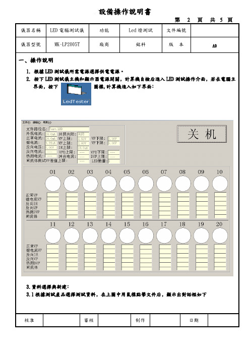
儀器名稱LED電腦測試儀功能Led燈測試文件編號儀器型號MK-LP2005T 廠商銘科版本A0一﹑操作說明1.根據LED測試儀所需電源選擇供電電源。
2. 按下LED測試儀主機和顯示器電源開關﹐計算機自檢后進入LED測試操作介面﹐若在電腦主界面﹐按下圖標,計算機進入如下界面﹕3.資料選擇與新建﹕3.1根據測試產品選擇測試資料﹐在上圖中用鼠標點擊文件后﹐顯示出對話框如下核准審核制作日期儀器名稱LED電腦測試儀功能Led燈測試文件編號儀器型號MK-LP2005T 廠商銘科版本A03.2在上圖中﹐用鼠標點擊“打開”顯示對話框如下3.3根據測試產品﹐選擇所需資料﹐用鼠標點擊“打開”即可。
核准審核制作日期儀器名稱LED電腦測試儀功能Led燈測試文件編號儀器型號MK-LP2005T 廠商銘科版本A03.4重復3.1操作﹐出現對話框后﹐用鼠標點擊“新建”﹐出現下圖對話框﹕3.5根據測試條件選擇測試項目﹐現我司LED只需測試外觀電流﹑正常VF測試﹑微電流VF測試和逆向電流測試﹐根據SOP要求設置相對應參數﹐按確認后﹐儀器彈出如下對畫框﹕儀器名稱LED電腦測試儀功能Led燈測試文件編號儀器型號MK-LP2005T 廠商銘科版本A03.6用鼠標點擊“是”﹐儀器顯示如下對話框﹕在文件名處﹐輸入產品名稱﹐按“保存”即可存檔4.聲音設定:4.1在計算機桌面雙擊我的電腦點擊”D”盤聲音設定報警聲音選擇所需報警聲音﹐按下復制返回到“C”盤 Program Files Led Tester 按粘貼后并修改文件名為Fail或PASS。
即聲音設定完成。
5.校正﹕若校正誤差大﹐在測試界面﹐按Ctrl+F8,即調出隱藏之“測試值調整”如下圖﹐根據偏差大小修正即可。
核准審核制作日期儀器名稱LED電腦測試儀功能Led燈測試文件編號儀器型號MK-LP2005T 廠商銘科版本A06.測試﹕6.1根據測試產品調出資料﹐連接測試治具后﹐按下踏板開始測試。
灯检机操作
灯检仪SOP类别: 操作规程 1/31. 目的:建立安瓿注射液异物自动检查机的标准操作规程,确保设备正常运转,保证设备使用的安全性、有效性。
2. 范围:适用于JAZ1-20/300安瓿注射液异物自动检查机的操作。
3. 责任人:设备维修人员、操作人员。
4. 规程:4.1 批量检查前的准备与检查:检查机器内清洁卫生情况4.1.1 检查电源连接是否正常4.1.2 开启各电源开关4.1.3 打开电脑的ups工控机电源开关,当屏幕显示无信号字幕后按启动按钮,系统启动4.1.4 打开照明开关,取出左右检测区各六个摄像头盖和六个光源的UV镜盖,并将左右检测区的各六个光源的UV镜擦拭干净。
4.1.5 分别检查机器左右检测区内部关键机械部位情况(包括进瓶网带及下面2根滚轴、进瓶拨轮及进瓶挡块、进瓶大圆弧栏栅、66个支撑体表面、出瓶拨轮及小圆弧栏栅、绞龙、分瓶器等)看机器内部是否正常。
66个支撑体表面是否平整。
刹车片是否有效。
4.1.6 将主机与网带旋钮旋为0,双击“各电机调试”按钮,“各电机调试”程序开启,再点击“主电机与旋瓶电机运转”按钮,将主机调至慢速,用双指测试法检查旋瓶座轴承是否转动灵活正常,刹车是否正常,检查结束后,再点击“点击停止”按钮,电机停止运转。
4.1.7 然后检查剔瓶动作:分别交替点击剔瓶动作及电机停止运转两到三次,看分瓶器是否摆动及摆动角度与出瓶栏栅是否对齐,关闭程序。
4.1.8 开启左检测区“灯检机”程序,选择检测规格,点击“系统调试”按钮,点击“摄像头1”按钮,然后点击“机器运转”按钮,慢慢旋转主机按钮,在显示器上观察摄像头1图像质量,点击“关闭摄像头”按钮。
摄像头2、3、4、5、6的操作同“摄像头1”。
确保六个摄像头的图像清晰,图像位置为中间稍稍偏左,再点击“机器停止”按钮。
点击“调试结束”按钮,再点击“退出系统“按钮。
4.1.9 点击“主电机开启”按钮,慢慢旋动主机按钮至最快,观察光源是否对准通光孔,检查完毕,点击“电机停止”按钮,关闭各运转电机,关闭程序。
LED光色电综合测试系统作业指导书
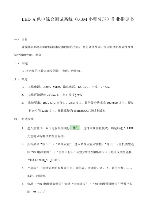
LED光色电综合测试系统(0.3M小积分球)作业指导书一、 目的让操作员熟练准确的掌握本仪器的操作方法,避免硬件故障,保证测试的准确性及维持仪器的性能、寿命。
二、 用途LED光源的实验室光度测量:光度、色度值。
三、 概述1、工作电源:220V,50Hz,输出电压:DC 30V,电流:0~5A。
2、工作环境温度25℃±2℃,相对湿度≤75%3、系统要求:RS-232-C串行口,USB接口,显示器分辨率在800×600以上,硬盘剩余空间128M以上,操作系统为WindowsXP及以上版本。
四、 测试步骤1、进入主窗口:双击电脑桌面图标,选择常规测量模式,确定后进入LED光色电分析测试系统主界面。
2、点击菜单“操作”→“系统设置”,进入系统设置对面框。
“通讯”→主机类型选择“WY电源主机”→“主机串行口”设置对应仪器的串行口→光谱仪类型选择“HAAS2000_V1_USB”。
3、“显示”→选择需要的参数显示值,如色温、光通量、VF、IF、显色指数、x,y、备注、时间等。
4、选项→“WY电源调节模式”选择“快速模式”→“WY电源通讯模式”设置“多机(9Bits)。
”5、“确定”后退出→点击菜单“操作”→“设置最大输出电压”设置合适的待测LED光源的最大驱动电压;6、“确定”后退出→点击菜单“操作”→“修正系数K”设置“光通量修正系数”。
7、返回主窗口,从右图中选择“使用光谱仪色参数”→设置正确的工作电流→“积分时间”设置“自动积分”→“光度量程档位”选择“自动”→“设置”选择“快速测量模式”。
8、将样品装夹在专用夹具上放入积分球→在菜单栏单击图标,启动测试模式→单击“测试[F3]”启动测试。
9、主窗口将显示当时样品的光色电参数值及光谱图。
10、测试完毕后,点击菜单栏上的“保存”按钮将保存原始文件,光标移到图标将下拉显示“设置自动保存Excel文件名及位置”后单击即可命名文件及设置保存位置。
- 1、下载文档前请自行甄别文档内容的完整性,平台不提供额外的编辑、内容补充、找答案等附加服务。
- 2、"仅部分预览"的文档,不可在线预览部分如存在完整性等问题,可反馈申请退款(可完整预览的文档不适用该条件!)。
- 3、如文档侵犯您的权益,请联系客服反馈,我们会尽快为您处理(人工客服工作时间:9:00-18:30)。
5.3.5将测试治具推入积分球开口或光强探头(推入光强探头时要时治具与探头通过卡槽固定),点击 ,再单击Measure或键盘上的F8即测试一次。当测试时出现“嘀嘀”的声音时,需等待10s左右后再次测试;
5.3.6测试完成后,在数据显示处单击鼠标右键,选择“export”,保存数据,数据命名按实验室样品命名规范确定。
≤1.5%
≤2.0%
表1光通/光强点检限值
5pcs器件色坐标偏差绝对值的平均值
5pcs器件色坐标偏差绝对值的最大值
≤0.0010
≤0.0015
表2色坐标点检限值
光谱仪参数
积分时间(Integration Time)
最小信号水平(Minimum signal level)
最大积分时间(Max. integration time)
Use density filter
自动积分(Auto Ranging)
50%
1s
√
电参数
Source
Flow Time
Settling Time
Turn off afer Measurement
Current Source
Fix:0ms
0ms
√
备注
若修改了如上任一参数,请重启软件后再进行测试。
表3标准机参数设置
5.5发光角度测试
5.5.1在光谱仪上插入标有0076145G1光纤;
5.5.2在CSD 315上按下Main Switch及Power开关;
5.5.3打开LEDGON软件,参数设置见5.3.3;
5.5.4打开暗箱门,利用配件螺丝刀拧松探头口,取出相应治具按正负极方向放入样品;
5.5.5点击图标 ,待测试探头移至正向朝外时,即可放入夹具(保证线安装在相应位置使暗箱在关闭时能够紧密闭合);
页数
共7页
E.C.N
七、附件
7.1附件一:设备仪器日常定期保养卡
7.2附件二:测试机点检记录表
7.3附件三:设备使用登记表
版别
修订日期
文件修订内容
备注
A/0
2017-9-13
新制定
/
針对其工程变更項目內容加注其处理对策。
处理方式
项目代码
处理对策
a
b
c
代号a.旧材料处理方式b.生产线上半成品c.旧库存
变更注记
版别
A/0
2017年9月13日
5.5.8点击 ,在 输入316mm,点击OK即可进行测试;
5.5.9测试完成后保存测试数据见5.3.6,也可点击Save as保存测试原始状态。
5.6校准
5.6.1定标参考《实验室MSA SOP》;
5.6.2每年进行一次计量,计量过后进行一次确认。
六、பைடு நூலகம்意事项
6.1本设备要指定的人员才可操作。
6.2光通光纤接到测试设备的输入口处,安装光纤时必须小心,不要折叠光纤,不要过度弯曲光纤(弯曲后的直径要不小于40cm)。
5.3光强/光通测试
5.3.1测试前根据所测项目换相应光纤,测试光通在光谱仪上插入标有0076145i1光纤,测试光强在光谱仪上插入标有0076145E1光纤,并且打开积分球开口或光强探头。
5.3.2将测试治具连接线可根据颜色对应连接keithley电源插孔。
5.3.3打开相应测试软件,在菜单栏 输入电流值,按enter键,若需要改变电压值,应先在菜单栏tool-unlock输入密码,然后点击parameter,再点击current source,在voltage compliancs输入电压值,按两次ok退出即可完成电流及电压的设置。
一、目的:
使操作者作业规范化、标准化,作业有章可循,保证LED光学测试系统IS机光电分析测量系统的正确使用和管理,以及保证测试的稳定性和可靠性。
二、适用范围:
适用于型号2425-100W-sourceMeter(以下称IS机)的LED光电色测试系统。
三、权责:
3.1检测员
3.1.1按此文件依相应实验项目进行作业。
5.5.6点击 ,测试探头移至测试区域,再将测试治具用连接线与keithley电源连接好,关闭暗箱门;
5.5.7使用自动积分时间,点击 ,测试观察Minimum signal level值是否在75±5%之间,换成手动积分 ,若不满足条件修改积分时间,待测试时Minimum signal level值在此范围内即可;
3.2.3安排设备维修及外部校准事宜。
四、保养项目:
4.1检查机台开关是否连接好。
4.2上班前对设备及周围环境进行6S保养。
五、操作步骤:
5.1工作环境
温度25℃±2℃,湿度40%RH~60%RH,如温湿度达不到要求,通过调节空调温度、打开抽湿机、加湿机等调节温湿度,达到要求的条件。
5.2启动和预热
6.3每次测试结束,必须把积分球/光强探头的测试端口封闭。
6.4测试员更换测试端口时,不能让积分球白色涂层面板沾上灰尘,不可划花。
6.5当测试发光角度时暗箱夹具卡槽出现卡动时,旋转夹具卡槽致1/2左右处,方可回复正常。
6.6禁止将易燃易爆品放入设备。
6.7使用设备前需要在《设备使用登记表》上进行登记,只有经过培训的人员才能进行设备的操作。
5.3.7测试过程中,测试软件的常见参数设置如表3,这些参数如果因特殊要求进行了修改,应立即重启软件,才能重新开始测试。
5.4点检
5.4.1点检时间每日上午8点;
5.4.2点检使用已制备好的点检样品5pcs薄杯2835器件。点检时需要使用黑色2835不挡光夹具(编号为:TS2835E),点检电流为100mA;
3.1.2按保养项目对IS机光电分析测量系统进行定期保养,并记录于《设备仪器日常定期保养卡》中。
3.1.3每天对IS机光电分析测量系统进行点检。
3.1.4对IS机光电分析测量系统进行内部校准。
3.2设备管理员
3.2.1联系人员对电脑操作系统进行备份。
3.2.2由设备管理员对IS机光电分析测量系统的使用说明书、光盘、标准灯以及其他配件等进行保管,以及对相关的电子版资料进行备份。
5.2.1连接光纤。如测试光通,将标有光通的光纤插入波长仪左侧的开口,定位销在正上方,缓慢旋转保护盖固定光纤,如测试光强或发光角度,则将标有光强或发光角度的光纤按照同样的方法插入波长仪开口位置。
5.2.2按顺序先后打开光谱仪、keithley电源和电脑。
5.2.3 IS机预热至少0.5h。
5.2.4如测试光通,则选择 Flux,如测试光强,则选择 ,如测试发光角度,则选择 。
5.4.3操作步骤参考5.3
5.4.4检测员使用5pcsLED器件在IS机上测试,将测试数据输入《光学测试机点检记录表》中,如每个器件光通/光强、色坐标与基准值的偏差绝对值满足表1和表2的所有条件,才判定合格。
5pcs器件光通/光强偏差百分比绝对值的平均值
5pcs器件光通/光强偏差百分比绝对值的最大值