ESP8266-12 WiFi模块用户手册V1.0
esp8266-01wifi模块用户手册v1.0

ESP8266 WiFi模块用户手册_ 术语和缩写 (4)k 产品简介 (5)二 捱遊 (5)产品特性 (5)模块封装....模块基本参数 硬件介绍 功耗二射频指标 ............................................................................................................................................................................................. 12 二A± ...................................................................................................................................................................................................... 13 二WiFi 天线 ................................................................................................................................................................................................... 14 二 推荐炉温曲线 .. (14)乙 功能描述 (15)二主要功能 ..................................................................................................................................................................................................... 15 二工作模式 ..................................................................................................................................................................................................... 15 ・ 应用领域 ..................................................................................................................................................................................................... 15 二AiCloud .................................................................................................................................................................................................... 15 L全功能测试版介绍 .............................................................................................................................................................................................. 16 二测试步骤 ..................................................................................................................................................................................................... 17 二 基砂AT 指令 (20)测试AT (20)二 WiFi 功能AT 指令 (20)选择WiFi 应用模式:AT+CWM0DE (20)列出当前可用接入点:AT+CWLAP (21)加入接入点:AT+CWJAP (21)退出接入点:AT+CWQAP (22)设置AP 模式下的参数:AT+CWSAP (22)TCPIP AT 指令 (23)建立 TCP/UDP 连接:AT+CIPSTART (23)获得 TCP/UDP 连接状态:AT+CIPSTATUS (23)启动多连接:AT+CIPMUX (24)发送数据:AT+CIPSEND (25)关闭 TCP/UDP 连接:AT+CIPCL0SE (25)6 7 8 11获取本地IP地址:AT+CIFSR (26)配置为服务器: (27)选择 TCPIP 应用模式:AT+CIPMODE (30)设置服务器主动断开的超时时间:AT+CIPST0 (30)设置波特率:AT+CI0BAUD (30)4. 产品试用 (31)表格目录表格1 术语和缩写4表格2 模块技术规格7表格3 Pin脚定义10表格4 功耗数据11表格5 射频指标12 &图目录图2 模块管脚排列图 (8)图3 天线图 (13)图4 V/iFi射频参考电路图 (14)图5 推荐回流曲线图 (14)图6 全功能测试板板正面视图 (16)术语和缩写表格1 术语和缩写1.产品简介1.1.(1.2.概述ESP8266是一款超低功耗的UART-WiFi透传模块,拥有业内极富竞争力的封装尺寸和超低能耗技术,专为移动设备和物联网应用设计.可将用户的物理设备连接到Wi-Fi无线网络上,进行互联网或局域网通信,实现联网功能。
esp8266 技术参考 说明书
3.2.1.
平台介绍 ......................................................................................................................13
第9章
I2C 接口口说明
描述 I2C 的功能、master 接口口和使用用示例例。
第 10 章
I2S 接口口说明
描述 I2S 的功能、模块配置和接口口函数说明。
第 11 章
UART 接口口说明
描述 UART 的功能、硬件资源、参数配置、配置中断、中断处理理
函数示例例流程和屏蔽上电打印。
第 12 章
PWM 接口口说明
附录
附录
GPIO 寄存器器、SPI 寄存器器、UART 寄存器器、定时器器寄存器器。
描述 SDIO 的功能、DEMO 实现方方案、ESP8266 端及 STM32 端
软件说明。
描述 SPI 的功能、SPI 主/从机协议格式和 API 函数说明。
描述 SPI 的功能、从机协议格式、从机状态定义与中断线行行行为和
应用用场景 1 参数配置 .....................................................................................................8
2.3.2.
应用用场景 2 参数配置 .....................................................................................................9
1.3. 串串行行行外设接口口(SPI/HSPI) .....................................................................................................1
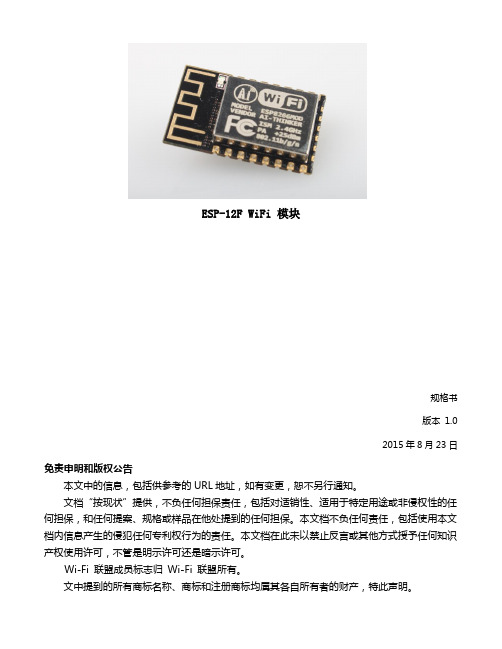
ESP8266 安信可ESP-12F WIFI模块规格书
规格书版本1.02015年8月23日免责申明和版权公告本文中的信息,包括供参考的URL地址,如有变更,恕不另行通知。
文档“按现状”提供,不负任何担保责任,包括对适销性、适用于特定用途或非侵权性的任何担保,和任何提案、规格或样品在他处提到的任何担保。
本文档不负任何责任,包括使用本文档内信息产生的侵犯任何专利权行为的责任。
本文档在此未以禁止反言或其他方式授予任何知识产权使⽤许可,不管是明示许可还是暗示许可。
Wi-Fi 联盟成员标志归Wi-Fi 联盟所有。
文中提到的所有商标名称、商标和注册商标均属其各自所有者的财产,特此声明。
注意由于产品版本升级或其他原因,本手册内容有可能变更。
深圳市安信可科技有限公司保留在没有任何通知或者提示的情况下对本手册的内容进行修改的权利。
本手册仅作为使用指导,深圳市安信可科技有限公司尽全力在本手册中提供准确的信息,但是深圳市安信可科技有限公司并不确保手册内容完全没有错误,本手册中的所有陈述、信息和建议也不构成任何明示或暗示的担保。
目录1. 产品概述 (2)1.1. 特点 (3)1.2. 主要参数 (4)2. 接口定义 (5)3. 外型与尺寸 (7)4. 功能描述 (9)4.1. MCU (9)4.2. 存储描述 (9)4.3. 晶振 (9)4.4. 接口说明 (10)4.5. 最大额定值 (11)4.6. 建议工作环境 (11)4.7. 数字端口特征 (11)5. RF 参数 (12)6. 功耗 (13)7. 倾斜升温 (14)8. 原理图 (15)9. 产品试用 (16)1.产品概述ESP-12F WiFi 模块是由安信可科技开发的,该模块核心处理器ESP8266 在较小尺寸封装中集成了业界领先的Tensilica L106 超低功耗32 位微型MCU,带有16 位精简模式,主频支持80 MHz 和160 MHz,支持RTOS,集成Wi-Fi MAC/ BB/RF/PA/LNA,板载天线。
ESP8266 固件下载协议 V1.2 应用指南说明书

Byte 0 1 2~3
4~7 8~n 8 9
Data type
Table 2-1. Packet Header Format Request
Response
Type
Always 0x00.
Always 0x01.
2.2. Packet Body...............................................................................................................................4
3. Firmware Image Format ........................................................................................................5 A. Appendix - Programming Examples .....................................................................................6
1.2. Download Procedure .................................................................................................................2
2. Transmission Protocol ...........................................................................................................3 2.1. Packet Header ...........................................................................................................................3
ATK-ESP8266WIFI用户手册_V1.0

ATK-ESP8266WIFI⽤户⼿册_V1.0⾼性能UART-WIFI 模块ATK-ESP8266 WIFI ⽤户⼿册修订历史版本⽇期原因V1.002015/6/10第⼀次发布User Manual⽬录1.特性参数 (1)2.使⽤说明 (2)2.1模块引脚说明 (2)2.1安信可ESP8266-12F WIFI模块 (3)2.2模块使⽤说明 (4)2.2.1 功能说明 (4)2.2.1.1 透传模式 (4)2.2.2 使⽤前准备 (4)2.2.3 硬件连接 (4)2.2.4 指令结构 (5)2.2.3 基础AT指令 (5)2.2.3.1 AT (5)2.2.3.2 AT+RST (6)2.2.3.3 AT+GMR (6)2.2.3.4 ATE (6)2.2.3.5 AT+RESTORE (6)2.2.3.6 AT+UART (6)2.2.4 WIFI功能AT指令 (7)2.2.4.1 AT+CWMODE (8)2.2.4.2 AT+CWJAP (8)2.2.4.3 AT+CWLAP (9)2.2.4.4 AT+CWQAP (9)2.2.4.5 AT+CWSAP (9)2.2.4.6 AT+CWLIF (10)2.2.4.7 AT+CWDHCP (10)2.2.4.8 AT+CW AUTOCONN (11)2.2.4.9 AT+CIPSTAMAC (11)2.2.4.10 A T+CIPAPMAC (11)2.2.4.11 A T+CIPSTA (12)2.2.4.12 A T+CIPAP (12)2.2.5 TCP/IP⼯具箱AT指令 (12)2.2.5.1 AT+CIPSTA TUS (13)2.2.5.2 AT+CIPSTART (13)2.2.5.3 AT+CIPSEND (14)2.2.5.4 AT+CIPCLOSE (14)2.2.5.5 AT+CIFSR (15)2.2.5.6 AT+CIPMUX (15)2.2.5.7 AT+CIPSERVER (16)2.2.5.8 AT+CIPMODE (16)2.2.5.9 AT+CIPSTO (16)2.2.5.10 A T+CIUPDA TE (17)2.2.5.11 A T+PING (17)2.2.6 基本AT指令测试 (17)2.2.6.1 AT+RST 重启模块,如图2.2.6.1.1 (18)2.2.6.2 AT+GMR 查看版本信息,如图2.2.6.2.1 (19)2.2.7 单连接client,透传模式 (19)2.2.8 多连接server (23)3 结构尺⼨ (26)4 其他 (27)1.特性参数ATK-ESP8266是ALIENTEK推出的⼀款⾼性能的UART-WiFi(串⼝-⽆线)模块,ATK-ESP8266板载ai-thinker公司的ESP8266模块,该模块通过FCC,CE认证,可直接⽤于产品出⼝欧美地区。
低功耗WIFI芯片ESP8266规格书

桹ⷧ㘶Ⓟ⣷㘴㟅Ⓙ䤓庆㻑㈏㈏㢾浧抮庆㻑᧨力 APB 㲰⧦㘴㟅Ⓙ䤓㈏㈏㢾幎桽⹓ⷧ⣷䤓 庆㻑ᇭ APB 㲰⧦⏔㇢屲䪐⣷᧨⇕♹♾ⅴ幎桽 ESP8266 㲰⧦␔♾冥䲚䤓⹓ⷧ⣷ᇭ䟀ℝ♠抐 ⦿⧏ₜ⚛᧨APB 庆㻑♾厌Ⓙ才㡯兎䟄㘴㟅⣷ᇬSI/SPIᇬ㧉 SDIOᇬGPIOᇬUARTᇬ ⸭㢅㢅朮(RTC)ᇬMAC 㒥㟿ⷦ⪉サᇭ
Ҁ䪛ؑ、ᢰ
2013 ᒤ 12 ᴸ 09 ᰕ
ESP8266 802.11bgn 㤉厌ℶ❐
1
グϻ
⃟曺㤉厌℡勣♿ಧಧESCP 㕴㦘浧㊶厌㡯兎 SOC᧨全䲊┷♿幍帰サ㧴䰞檂᧨⸒ ⅴ㦏⇝㒟㦻㙟∪㦏⮶⸭䞷㊶᧨ WiFi ┮厌⏴␅Ⅵ侊兮㙟∪㡯棟♾厌ᇭ
ሴ仁 balun
ᔰޣ
ሴ仁 ᧕᭦ ሴ仁 ਁሴ
VCO
12 | P a g e
Ҁ䪛ؑ、ᢰ
2013 ᒤ 12 ᴸ 09 ᰕ
ESP8266 802.11bgn 㤉厌ℶ❐
8
8.1
CPUȡႈט়ᣕओ
CPU
扨㷍唾䓖⏴ℕ₹怔⇝┮䘖 32 ⇜㈽⨚ CPU᧨サ㦘 16 ⇜位丏㲰㆞ᇭ♾ⅴ抩扖ⅴₚ㘴 ♲扭㘴年 CPU᧶
䘎᧕ᆈۘ᧗ࡦಘǃҏਟԕ⭘ᶕ䇯䰞ཆ᧕䰚ᆈⲴ㕆⸱ RAM/ROM ᧕ਓ(iBus) ਼ṧ䘎᧕ᆈۘ᧗ࡦಘⲴᮠᦞ RAM ᧕ਓ(dBus) 䇯䰞ᇴᆈಘⲴ AHB ᧕ਓ JTAG 䈳䈅᧕ਓ
↯抐 802.11n, MCS7, POUT =+14dBm 㘴㟅 802.11b, ▔栎 1024 ⷦ唑, -80dBm 㘴㟅 802.11g, ▔栎 1024 ⷦ唑, -70dBm 㘴㟅 802.11n, ▔栎 1024 ⷦ唑, -65dBm 侊兮㈔㧉㲰㆞ 䂀ㄵ䧰䦯 唑厌㲰㆞ DTIM 1 唑厌㲰㆞ DTIM 3 ␂㧉
2A-ESP8266__IOT_SDK_User_Manual__CN_v1.0.1
ESP8266 ⺟母板上跳线设置为 MTDO:0,GPIO0:0,GPIO2:1,进入入下载模式。
操作步骤如下:
• 如下绿色色显示示区域,选择要烧录的 bin 文文件 ➝ 填写烧录地址 ➝ 勾选待烧录的选项。
Espressif Systems Confidential
2/12
Friday, April 17, 2015
" "&TQSFTTJG4ZTUFNT "
&414%,6TFS.BOVBM
Table of Contents
1. 前言言...............................................................................................................4
Espressif Systems Confidential
4/12
Friday, April 17, 2015
" "&TQSFTTJG4ZTUFNT "
&414%,6TFS.BOVBM
• 设置 COM 口口和波特率。
• 点击 "START" 开始下载。 • 下载完成后,将⺟母板断电,修改跳线为运行行模式,上电正常运行行。
更多ESP8266的信息,请访问:/ 新手手指南位于BBS /viewforum.php?f=21
2. 开发工工具
以下列出建议使用用的串口口工工具和烧录工工具,客户也可以选择使用用其他同样功能的工工具。串口口工工具, 用用于打印信息,进行行调试;烧录工工具,用用于下载软件到 flash 中。
Arduino---ESP8266WIFI模块

Arduino---ESP8266WIFI模块⽬录⼀:Arduino安装(内容截图如下:最简单⽅法)选⽤NodeMCU 1.0即可⼆:简单测试void setup() {// put your setup code here, to run once:pinMode(LED_BUILTIN,OUTPUT); //测试灯}void loop() {// put your main code here, to run repeatedly:digitalWrite(LED_BUILTIN,LOW);delay(1000);digitalWrite(LED_BUILTIN,HIGH);delay(1000);}LED_BUILTIN中builtin是内建意思,为内建LED灯,可直接⽤于测试三:引脚对应引脚编号对应数字D016D15D24D30D42D514D612D713D815D93D101四:简单使⽤案例:⽆线控制LED开关#include <ESP8266WiFi.h> //引⼊模块#ifndef STASSID#define STASSID "Tenda_064E38"#define STAPSK "YM123456789"#endifconst char* ssid = STASSID;const char* password = STAPSK;// Create an instance of the server// specify the port to listen on as an argumentWiFiServer server(80); //开启板⼦的80端⼝void setup() {////在波特率为9600~38400之间,波特率的增长倍数与传输速率的增长倍数基本相同,但是在波特率⼤于192000以上时,传输速率基本没有任何提⾼。
ESP8266串口wifi模块使用手册

ESP8266串口wifi模块使用手册
一、模块引脚介绍
正常使用只需要VCC,GND,URXD,UTXD,CH_PD这5个io就可以,其中CH_PD正常使用时接高电平。
其他接口一般用于模块烧写固体是用到。
模块出厂已经烧有固体,波特率为115200。
二、模块与407开发板(高配版)V3.1连接
由于wifi模块接口与网络芯片DP83838公用IO口,所以在使用wifi模块时,需要把P5,上图红色圈出来的短路帽全部拆掉,不要接。
三、实验操作与现象
1、P5短路帽全部拆掉
2、板子上电,下载配套的例程程序
3、板子断电,插上wifi模块
4、板子上电后,代码运行配置wifi模块工作在服务器
5、此时手机wifi搜索,可搜索到名为“qiming_wifi”的热点,连接此热点,密码为:0123456789
6、打开“启明WIFI”app,输入IP: 192.168.4.1 端口号5000
7、点击“连接”,连接成功后手机APP就可以控制开发板了第5、6步可以在程序中设置用户自己所需参数。
esp8266 教程

esp8266 教程ESP8266教程:连接WiFi网络步骤一:准备工作1.1 确保你已经具备以下物品:- ESP8266模块- 电脑- USB转串口模块- 杜邦线1.2 安装USB驱动程序在使用ESP8266之前,我们需要先安装USB转串口模块所需的驱动程序。
根据你所使用的转接模块型号,下载并安装相应的驱动程序。
步骤二:连接硬件2.1 将ESP8266与USB转串口模块连接起来。
使用杜邦线将ESP8266的VCC引脚连接到USB转串口模块的VCC引脚,将GND引脚连接到GND引脚,将TX引脚连接到RX引脚,将RX引脚连接到TX引脚。
2.2 将USB转串口模块连接到电脑的USB接口上。
步骤三:编写代码3.1 打开Arduino IDE,新建一个代码文件。
3.2 导入ESP8266库在Arduino IDE中,点击"工具"->"管理库",搜索并安装ESP8266库。
3.3 编写代码接下来,我们开始编写代码。
以下是一个简单的示例,用于连接WiFi网络。
```cpp#include <ESP8266WiFi.h>const char* ssid = "YourWiFiNetworkName";const char* password = "YourWiFiNetworkPassword";void setup() {Serial.begin(115200);WiFi.begin(ssid, password);while (WiFi.status() != WL_CONNECTED) {delay(1000);Serial.println("Connecting to WiFi...");}Serial.println("Connected to WiFi!");}void loop() {// 这里可以添加你的代码逻辑}```备注:将"YourWiFiNetworkName"替换成你的WiFi网络名称,将"YourWiFiNetworkPassword"替换成你的WiFi网络密码。
ESP8266-08-WiFi模块用户手册V1.0知识讲解

E S P8266-08-W iF i模块用户手册V1.0ESP8266 WiFi模块用户手册V1.0目录术语和缩写 (4)1.产品简介 (5)1.1.概述 (5)1.1.1产品特性 (5)1.1.2模块封装 (6)1.1.3模块基本参数 (6)1.2.硬件介绍 (7)1.3.功耗 (10)1.4.射频指标 (11)1.5.尺寸 (13)1.6.WiFi 天线 (14)1.7.推荐炉温曲线 (14)2.功能描述 (15)2.1.主要功能 (15)2.2.工作模式 (15)2.3.应用领域 (16)2.4.AiCloud (16)3.全功能测试版介绍 (17)3.1.测试步骤 (18)3.2.基础AT指令 (22)3.2.1 测试AT (22)3.3.WiFi功能AT指令 (22)3.3.1 选择WiFi应用模式:AT+CWMODE (22)3.3.2列出当前可用接入点:AT+CWLAP (23)3.3.3 加入接入点:AT+CWJAP (23)3.3.4 退出接入点:AT+CWQAP (23)3.3.5设置AP模式下的参数:AT+CWSAP (24)3.4.TCPIP AT指令 (25)3.4.1建立TCP/UDP连接:AT+CIPSTART (25)3.4.2获得TCP/UDP连接状态:AT+CIPSTATUS (25)3.4.3启动多连接:AT+CIPMUX (26)3.4.4发送数据:AT+CIPSEND (27)3.4.5关闭TCP/UDP连接:AT+CIPCLOSE (27)3.4.6获取本地IP地址:AT+CIFSR (28)3.4.7配置为服务器: (29)3.4.8选择TCPIP应用模式:AT+CIPMODE (32)3.4.9设置服务器主动断开的超时时间:AT+CIPSTO (32)3.4.10设置波特率:AT+CIOBAUD (32)4.产品试用 (33)表格目录表格 1 术语和缩写4表格 2 模块技术规格7表格 3 Pin脚定义10表格 4 功耗数据11表格 5 射频指标12图目录图 2 模块管脚排列图 (8)图 3 尺寸图 (13)图 4 WiFi射频参考电路图 (14)图 5 推荐回流曲线图 (15)图 6 全功能测试板板正面视图 (17)术语和缩写表格 1 术语和缩写1.产品简介1.1.概述ESP8266是一款超低功耗的UART-WiFi 透传模块,拥有业内极富竞争力的封装尺寸和超低能耗技术,专为移动设备和物联网应用设计,可将用户的物理设备连接到Wi-Fi 无线网络上,进行互联网或局域网通信,实现联网功能。
WIFI模块EPS8266使用详述

用的这款各引脚功能:来至厂家提供的资料GPIO0 默认是工作模式(不接线)。
如果接了低电平就是下载模式(给模块刷固件!!),所以可以不接线,当然也可以接高电平。
反正一开始连接的时候CH_PD 必须为高电平。
其余的可以不接。
如果电脑的wifi 上显示了你的wifi 信号说明模块已经工作。
注意默认的波特率是115200!!!!!!设置好串口调试助手的波特率,再贴张图片吧防止亲们忘。
PIN FunctionDescription 1 URXD 1)UART_RXD ,接收;2)General Purpose Input/Output :GPIO3;2UTXD 1)UART_TXD ,发送;2)General Purpose Input/Output :GPIO1;3)开机时禁止下拉; 5RESET (GPIO 16) 外部Reset 信号,低电平复位,高电平工作(默认高); 6GND GND 8VCC 3.3V ,模块供电; 9 ANT WiFi Antenna11 GPIO0 1)默认WiFi Status :WiFi 工作状态指示灯控制信号;2)工作模式选择:上拉:Flash Boot ,工作模式;下拉:UART Download ,下载模式;12 ADC ADC ,输入范围:0V-1V ;13 GPIO15 下拉:工作模式;14 CH_PD 1)高电平工作;2)低电平模块供电关掉;15GPIO21)开机上电时必须为高电平,禁止硬件下拉;2)内部默认已拉高记得输入各种AT指令,勾选上“发送新行”些内部信息)然后输出READY!代表系统正系统启动后,系统会输出一堆乱码(其实不是乱码,系统启动后输出一常对于后面的操作--先提个醒,如果连接wifi出现连接不上的问题,可以发送AT+RESTORE 恢复出厂设置或刷固件先看秦时明月;;;;;;终于做好了,android客服端软件,(记得加权限,网络,和wifi。
ESP8266用户手册

ESP8266用户手册ESP8266是一种广泛使用的无线模块,由Espressif Systems开发,被广泛使用于物联网和嵌入式设备的应用。
ESP8266的设计目标是为IoT应用提供连接便捷、底层可编程性和低成本的方案,它采用了Tensilica的L106 Diamond系列的32位大小端MCU。
由于其强大的功能和易于使用性,ESP8266已经成为了DIY电子爱好者的最爱。
本文将详细介绍ESP8266用户手册,以帮助新手更好地使用该模块。
1. 硬件介绍ESP8266是一款集成了Wi-Fi的芯片,它与主控芯片之间通过串行通信进行交互。
ESP8266的主体尺寸为16mm x 24mm,并且它的引脚和结构都是十分紧凑的。
ESP8266通常工作在3.3V的电压下,但是如果需要与5V的主控芯片进行通信,就需要进行电平转换。
2. 软件介绍在软件方面,ESP8266支持多种开发平台和语言。
目前,ESP8266最受欢迎的开发平台是Arduino IDE,用户可以通过该平台进行快速的开发工作。
此外,ESP8266也支持其他语言和开发平台,例如Python、Lua等。
3. WiFi模式ESP8266支持三种WiFi模式: STA模式、AP模式和STA+AP 模式。
STA模式是指将ESP8266作为一个WiFi的客户端连接到一个现有的WiFi网络,AP模式是指将ESP8266作为一个WiFi热点使其它设备可以连接到它,STA+AP模式是指将ESP8266同时作为WiFi客户端和WiFi热点。
4. AT指令ESP8266可以通过AT指令进行控制。
当我们要将ESP8266作为单片机处理时,我们可以使用AT指令来控制它的各种功能。
AT指令通常以“AT”开头,其后跟着具体的指令。
例如,AT+GMR是一个用来获取ESP8266固件版本信息的指令。
5. 固件升级在使用ESP8266过程中,我们可能需要升级不同版本的固件以获取新的功能和修复BUG。
亿佰特(Ebyte)-低功耗WiFi模块(ESP8266)智能家居物联网改造应用方案

E103-W01-IPX使用手册V1.01.模块介绍 (2)1.1.特点简介 (2)1.2.基本用法 (3)1.3.电气参数 (3)1.4.电气特性 (3)2.功能简述 (4)2.1.引脚定义 (4)2.2.模块功耗 (5)2.3.应用原理图 (5)3.快速入门 (6)3.1.模块作为Client与TCP服务器连接 (6)3.2.模块作为AP建立TCP SERVER与PC无线连接 (15)3.3.Smart Config使用 (17)3.4.PWM的使用 (18)3.5.GPIO的使用 (19)3.6.ADC的使用 (20)3.7.修改串口波特率 (20)4.组网说明 (21)4.1.组网角色 (21)4.2.组网模型 (21)5.AT指令 (23)6.定制合作 (24)7.关于我们 (25)1.模块介绍1.1.特点简介E103-W01是一款超高性价比的100mW(20dBm)串口转Wi-Fi模块,贴片小体积封装,陶瓷天线与IPX并存,工作在2.4~2.4835GHz频段。
模块可使用串口进行数据收发,降低了无线应用的门槛。
E103-W01模块是基于Espressif公司的ESP8266EX芯片研发。
模块集成了透传功能,即拿即用,支持串口AT指令集,服务器AT指令集,用户通过串口即可使用网络访问的功能,广泛应用于穿戴设备、家庭自动化、家庭安防、个人保健、智能家电、配饰与遥控器、汽车、照明、工业互联网等领域。
E103-W01模块支持标准的IEEE802.11b/g/n协议和完整的TCP/IP协议栈,支持STA/AP/STA+AP工作模式、支持SmartConfig、串口透传、IO口控制、开机透传、PWM输出、AD检测等功能,简单配置后便可以非常便利的实现网络访问功能,最大限度减少开发者的工作和项目开发时间。
典型应用:模块特点:√无线抄表√210ms开机透传,掉线自动连接√无线传感√多种波特率√智能家居√支持SmartConfig配置功能√工业遥控及遥测√支持TCPServer、TCPClient、UDP√智能楼宇及智能建筑√三种工作模式STATION、AP、STATION&AP√高压线监测√支持14mA低功耗数据接收√环境工程√支持串口透明传输√高速公路√支持多种加密方式√小型气象站√支持模块串口AT指令配置√自动化数据采集√支持可配置4路PWM输出√消费电子√内置看门狗,永不死机√智能机器人√参数记忆,掉电保存√路灯控制√1路10位精度ADC1.2.基本用法1.3.电气参数1.4.电气特性2.功能简述2.1.引脚定义2.2.模块功耗参数最小值典型值最大值单位Tx802.11b,CCK11Mbps,POUT=+17dBm165170180mA Tx802.11g,OFDM54Mbps,POUT=+15dBm135140150mA Tx802.11n,MCS7,POUT=+13dBm115120130mA Rx802.11b,1024bytes包长,-80dBm182023mA Rx802.11g,1024bytes包长,-70dBm535665mA Rx802.11n,1024bytes包长,-65dBm535665mA 部分睡眠131518mA睡眠0.80.9 1.1mA深度睡眠91011uA关机0.40.50.6uA 2.3.应用原理图注意:供电电源必须保证在3.0V~3.6V,为保证模块能稳定工作,建议外部选择电流大于300mA的LDO。
迪文WIFI模块使用指南 V1.1说明书

RMA 报警 保留
0x401 0x404
3 D2=需要上传的 RMA 变量存储器字地址。
D1 : D0=需要上传的 RMA 变量存储器字长度。 12 保留。
高字节=0x5A 表示设备描述有效。
设备描述 (设备描述)
0x410
0x411 0x413 0x414 0x416
低字节=设备描述文本的编码方式和长度。 1
每个 Buffer 固定占 2304 个字(0x900)空间,顺序往后排。
5A
单个 Buffer 定义(前 512 字节是控制接口,后面 4KB 是数据):
00
0x44A
D0:0x5A 表示启动一次这个 buffer 的远程升级,CPU 处理后清零。
08
D1:远程升级空间选择,0x00-0x03,4 个远程升级空间之一。
0x430
RMA 自动刷新服务器的时间间隔,0x0000-0xFFFF,单位为 0 . 1 秒。 1 0x0000 表示不需要自动刷新。
推荐值 5AA5
全 00 全 00
5A45
00000001 0001 自定义
DGUS2_T5UID1
012C
设备描述 (RMA 映射)
设备描述 (远程升级)
0x431 0x432
迪文 WIFI 模块使用指南 V1.1
1. 概述
为了让迪文智能液晶屏轻松方便的连接互联网,迪文架设了自己的云服务器,并在 DGUS 系统之上,将连接 互联网的接口进行整合,这样以后开发带网络功能的智能迪文屏将会非常简单方便。
目前支持的液晶屏平台有 T5UID1、T5UID2 以及 T5L_ASIC。支持的产品有 86 盒产品、网络屏等。 迪文 WIFI 方案优势主要体现在以下三个方面: 1、开发效率 基于 DGUS 架构,单机功能实现后,单片机零代码即可实现配网和数据上传。工程师只需要对数据地址做好 规划即可。将复杂的 JSON 协议解析放在云端处理,节省单片机资源,提高开发效率。客户可以将精力集中在产品 核心功能上。 2、稳定性 方案已经将主芯片(GUI)、WIFI 模块、MQTT 服务器之间协议打通,形成 UI+IOT 集成式解决方案,减少客户 开发的环节数,减少沟通成本,降低开发中的不确定性,使整个方案稳定性提升。 3、成本 WIFI 模块作为迪文物联网解决方案一环,面对不同行业数万家客户,形成规模优势。直接和 WIFI 芯片原厂合 作,保证成本优势。
ESP8266 WiFi模块参数配置指南说明书
ESP8266 Phy Init Bin Parameter Configuration GuideVersion 1.0Espressif SystemsCopyright © 2018About This Guide This guide provides the parameter configuration for ESP8266 phy init bin.Release NotesDate Version Release notes2018.12V1.0Initial releaseDocumentation Change NotificationEspressif provides email notifications to keep customers updated on changes totechnical documentation. Please subscribe at https:///en/subscribe.CertificationDownload certificates for Espressif products from https:///en/certificates.Table of Contents....................................................................................... 1.Structure of ESP8266 Phy Init Bin 1.................................................................................... 2.Check Bits for ESP8266 Phy Init Bin 2.......................................................................................... 3.Version of ESP8266 Phy Init Bin 3............................................................................................... 4.Selection of Crystal Oscillator 4.......................................................................................................... 5.Six Levels of TX Power 5.......................................................................................... 6.TX Power for Various Data Rates 6.................................................................................................................... 7.TX Power Limits 7..........................................................................................7.1.Value Range of the TX Power Limits 77.2.Parameters for the TX Power Limits 7................................................................................................................................................................................................................. 8.RF Calibration 91. Structure of ESP8266 Phy Init Bin 1.Structure of ESP8266 Phy InitBin ESP8266 phy init bin is comprised of a 128-byte phy init data as shown in Table 1-1:Table 1-1. Structure of ESP8266 Phy Init BinName Sizephy init data128 bytes2. Check Bits for ESP8266 Phy Init Bin 2.Check Bits for ESP8266 PhyInit Bin The check bits for ESP8266 phy init bin are stored in byte zero of phy init data, and therelevant parameter is Init_bin_magic with default value of 0x5. The check bits are used forverifying the data location in ESP8266 phy init bin. If the parameter value is the same asthe default value when reading data, it is assumed that data are stored correctly inESP8266 phy init bin.Table 2-1. Check Bits for ESP8266 Phy Init BinLocation in phy init data Parameter Name Default Value Description0Init_bin_magic5For check3. Version of ESP8266 Phy Init Bin3.Version of ESP8266 Phy InitBinThe version information of ESP8266 phy init bin is stored in byte 1 of phy init data.For example, ESP8266_esp_data_bin_v08.bin represents Version 08, which is stored inbyte 1 as 0x8.Table 3-1. Version of ESP8266 Phy Init BinLocation in phy init data Parameter Name Default Value Description1Init_bin_version8phy init bin version4. Selection of Crystal Oscillator 4.Selection of Crystal OscillatorThe parameter crystal_sel allows you to select a crystal oscillator. The available options aregiven in Table 4-1. Currently, ESP8266 mainly supports 26 MHz and 40 MHz crystaloscillators.Table 4-1. Selection of Crystal OscillatorLocation in phy init data Parameter Name Default Value Description48crystal_sel10: 40 MHz crystal oscillator 1: 26 MHz crystal oscillator 2: 24 MHz crystal oscillator5. Six Levels of TX Power 5.Six Levels of TX PowerTX power can be switched between six levels. The indexes for the six levels are thenumbers from 0 to 5 at the end of the parameter names. For example, the index fortxpwr_qdb_0 is 0, representing the maximum TX power. From txpwr_qdb_0 totxpwr_qdb_5, the TX power decreases progressively.Default TX power settings can be found in Table 5-1.Table 5-1. Six Levels of TX PowerLocation in phy init data Parameter Name Default Value Unit Actual TX Power34txpwr_qdb_0780.25 dB19.5 dBm35txpwr_qdb_1740.25 dB18.5 dBm36txpwr_qdb_2700.25 dB17.5 dBm37txpwr_qdb_3640.25 dB16 dBm38txpwr_qdb_4600.25 dB15 dBm39txpwr_qdb_5560.25 dB14 dBm6. TX Power for Various Data Rates 6.TX Power for Various DataRates You can choose from any of the six TX power levels for different data rates. The columnDefault value in Table 6-1 contains the TX power index.Table 6-1. TX Power for Various Date RatesLocation in phy init data Parameter Name Data rate/mode DefaultValueDescription40txpwr_index_0MCS0, 1 Mbit/s, 2 Mbit/s, 5.5 Mbit/s, 11 Mbit/s,6 Mbit/s, 9 Mbit/s0Select txpwr_qdb_041txpwr_index_1MCS1, 12 Mbit/s0Select txpwr_qdb_0 42txpwr_index_2MCS2, 18 Mbit/s1Select txpwr_qdb_1 43txpwr_index_3MCS3, 24 Mbit/s1Select txpwr_qdb_1 44txpwr_index_4MCS4, 36 Mbit/s2Select txpwr_qdb_2 45txpwr_index_5MCS5, 48 Mbit/s3Select txpwr_qdb_3 46txpwr_index_6MCS6, 54 Mbit/s4Select txpwr_qdb_4 47txpwr_index_7MCS75Select txpwr_qdb_596txpwr_index_11b_en802.11b00: use txpwr_index_0 toset TX Power for 802.11b1: use bytes 97 and 98 toset TX Power for 802.11b97txpwr_index_11b_01 Mbit/s,2 Mbit/s0Select txpwr_qdb_098txpwr_index_11b_15.5 Mbit/s, 11 Mbit/s0Select txpwr_qdb_07. TX Power Limits7.TX Power LimitsThe TX power limits have been set mainly to limit the maximum powers for channels 1, 11,13 and 14 in order to conform to the certification test results.7.1.Value Range of the TX Power LimitsThe TX power limits are set against the six levels. The value range of the limits is [0:5],which includes the values presented in Table 7-1.7.2.Parameters for the TX Power LimitsThe parameters for the TX power limits are specified in Table 7-2. For example, if the valueof byte 78 is set to 2, the bytes 30-33 are enabled to configure the maximum TX powers for channels 1, 11, 13 and 14.Table 7-1. Values of the TX Power Limits ValueTX Power Limit (Unit: 0.25 dB)0txpwr_qdb_01txpwr_qdb_12txpwr_qdb_23txpwr_qdb_34txpwr_qdb_45txpwr_qdb_5Table 7-2. Parameters for the TX Power Limits Location inphy init data Parameter name Default value Description78fcc_enable 00: disable bytes 30-331: reserved2: enable bytes 30-33 to set maximum TXpower30mpwr_chan10Set the maximum TX power for 802.11 b/g/n mode at channel 1, range [0:5]. 0xf8 isan invalid parameter.31mpwr_chan110Set the maximum TX power for 802.11 b/g/n mode at channel 11, range [0:5]. 0xf8is an invalid parameter.7. TX Power Limits32mpwr_chan130Set the maximum TX power for 802.11 b/ g/n mode at channel 13, range [0:5]. 0xf8 is an invalid parameter.33mpwr_chan140Set the maximum TX power for 802.11 b/ g/n mode at channel 14, range [0:5]. 0xf8 is an invalid parameter.8. RF Calibration 8.RF CalibrationThe values of the parameter RF_calibration are shown in Table 8-1. To ensure better RFperformance, it is recommend to set RF_calibration to 3, otherwise the RF performancemay become poor.Table 8-1. Parameter of RF CalibrationLocation inphy init dataParameter name Default value Description114RF_calibration30 & 1: only used for setting TX power 2: No RF calibration3: Conduct all RF calibrationDisclaimer and Copyright NoticeInformation in this document, including URL references, is subject to change without notice.THIS DOCUMENT IS PROVIDED AS IS WITH NO WARRANTIES WHATSOEVER,INCLUDING ANY WARRANTY OF MERCHANTABILITY , NON-INFRINGEMENT, FITNESS FOR ANY PARTICULAR PURPOSE, OR ANY WARRANTY OTHERWISE ARISING OUT OF ANY PROPOSAL, SPECIFICATION OR SAMPLE.All liability, including liability for infringement of any proprietary rights, relating to use of information in this document is disclaimed. No licenses express or implied, by estoppel or otherwise, to any intellectual property rights are granted herein.The Wi-Fi Alliance Member logo is a trademark of the Wi-Fi Alliance. The Bluetooth logo is a registered trademark of Bluetooth SIG.All trade names, trademarks and registered trademarks mentioned in this document are property of their respective owners, and are hereby acknowledged. Copyright © 2018 Espressif Inc. All rights reserved.Espressif IoT Team。
ESP-12F无线网络模块详细说明中文

ESP -12F WIFI模块规格说明书ESP-12F WIFI模块规格说明书版本 1.02015年8月23日免责申明和版权公告本文中的信息,包括供参考的URL地址,如有变更,恕不另行通知。
文档“按现状”提供,不负任何担保责任,包括对适销性、适用于特定用途或非侵权性的任何担保,和任何提案、规格或样品在他处提到的任何担保。
本文档不负任何责任,包括使用本文档内信息产生的侵犯任何专利权行为的责任。
本文档在此未以禁止反言或其他方式授予任何知识产权使⽤许可,不管是明示许可还是暗示许可。
Wi-Fi 联盟成员标志归 Wi-Fi 联盟所有。
文中提到的所有商标名称、商标和注册商标均属其各自所有者的财产,特此声明。
注 意由于产品版本升级或其他原因,本手册内容有可能变更。
深圳市安信可科技有限公司保留在没有任何通知或者提示的情况下对本手册的内容进行修改的权利。
本手册仅作为使用指导,深圳市安信可科技有限公司尽全力在本手册中提供准确的信息,但是深圳市安信可科技有限公司并不确保手册内容完全没有错误,本手册中的所有陈述、信息和建议也不构成任何明示或暗示的担保。
ESP-12F规格说明书目录1.产品概述 (2)1.1.特点 (3)1.2.主要参数 (4)2.接口定义 (5)3.外型与尺寸 (7)4.功能描述 (9)4.1.MCU (9)4.2.存储描述 (9)4.3.晶振 (9)4.4.接口说明 (10)4.5.最大额定值 (11)4.6.建议工作环境 (11)4.7.数字端口特征 (12)5.RF 参数 (12)6.功耗 (13)7.倾斜升温 (14)8.典型应用原理图 (15)ESP-12F规格说明书1.产品概述ESP-12F WiFi 模块是由安信可科技开发的,该模块核心处理器 ESP8266 在较小尺寸封装中集成了业界领先的 Tensilica L106 超低功耗 32 位微型 MCU,带有 16 位精简模式,主频支持 80 MHz 和 160 MHz,支持 RTOS,集成 Wi-Fi MAC/ BB/RF/PA/LNA,板载天线。
ESP8266-DevKitS用户指南说明书

ESP8266-DevKitSUser GuideVersion 1.0Espressif SystemsCopyright © 2020About This Guide This user guide provides information on ESP8266-DevKitS-development board.Release NotesDate Version Release notes2020.02V1.0Initial release.Documentation Change NotificationEspressif provides email notifications to keep customers updated on changes totechnical documentation. Please subscribe here.CertificationDownload certificates for Espressif products from here.Tables of Contents ................................................................................................................................ 1.Overview 1.......................................................................................................... 2.Functional Description 2............................................................................................................ 3.How to Flash a Board 4................................................................................................................3.1.Hardware Preparation 4.........................................................................................................................3.2.Hardware Setup 4..........................................................................................................................3.3.Software Setup 4................................................................................................................. 4.Board Dimensions 5.............................................................................................................. 5.Hardware Reference 6............................................................................................................................5.1.Block Diagram 65.2.Power Supply Options 6...........................................................................................................................................................................................................................................5.3.Header Blocks 6A.Appendix—Learning Resources 8.........................................................................................................................................................................................................A.1.Must-Read Documents 8................................................................................................................A.2.Must-Have Resources 91. Overview 1.OverviewESP8266-DevKitS is Espressif’s flashing board designed specifically for ESP8266. It can beused to flash an ESP8266 module without soldering the module to the power supply andsignal lines. With a module mounted, ESP8266-DevKitS can also be used as a minidevelopment board like ESP8266-DevKitC.ESP8266-DevKitS supports the following ESP8266 modules:-ESP-WROOM-02-ESP-WROOM-02D-ESP-WROOM-02U2. Functional Description 2.Functional DescriptionFigure 2-1. ESP8266-DevKitSThis chapter introduces key components, interfaces and controls of ESP8266-DevKitSdevelopment board:•Spring PinsConnect and fix the module. These spring pins fit castellated holes on the module.• 2.54 mm Female HeadersConnect to jumper wires and other development boards. For description of femaleheaders, please refer to 5.3 Header Blocks.•USB-to-UART BridgeA single chip USB-UART bridge provides up to 3 Mbps transfers rates.2. Functional Description •LDO5V-to-3.3V Low dropout voltage regulator (LDO).•Boot ButtonDownload button. Holding down the Boot button and pressing the EN button initiates the firmware download mode. Then users can download firmware through the serial port.•Micro USB Port/Micro USB ConnectorUSB interface. Power supply for the board and the communication interface betweena computer and the board.•EN ButtonReset button. Pressing this button resets the system.•Power On LEDTurns on when the USB or power supply is connected to the board.3. How to Flash a Board 3.How to Flash a Board 3.1.Hardware Preparation• 1 x ESP8266 module of your choice• 1 x USB 2.0 cable (Standard-A to Micro-B)• 1 x PC loaded with Windows, Linux or Mac OS3.2.Hardware SetupPlease mount a module of your choice onto your ESP8266-DevKitS according to thefollowing steps:•Gently put your module on the ESP8266-DevKitS board. Make sure that castellated holes on your module are aligned with spring pins on the board.•Press your module down into the board until it clicks.•Check whether all spring pins are inserted into castellated holes. If there are some misaligned spring pins, place them into castellated holes with tweezers.3.3.Software SetupFor step-by-step introductions, please refer to ESP8266 Quick Start Guide.Note:1.To flash binary files, the ESP32 chip should be set to UART boot mode. This can be done either by theflash tool automatically, or by holding down the Boot button and tapping the EN button.2.After binary files have been flashed, please reset or power up your ESP32 module again to run theflashed application (this step is executed automatically by the flash tool by default).4. Board Dimensions 4.Board DimensionsFigure 4-1. Board Dimensions5.Hardware Reference 5.1.Block DiagramFigure 5-1. ESP8266-DevKitS Block Diagram5.2.Power Supply OptionsThere are three mutually exclusive ways to provide power to the board:•Micro USB port, default power supply•5V and GND header pins•3V3 and GND header pinsIt is advised to use the first option: micro USB port.5.3.Header BlocksTable 5-1. Header BlockLocation Label SignalL1G GNDL23V3VDD 3V3L33V3VDD 3V3L4EN CHIP_ENL5G GNDL614GPIO14L712GPIO12L813GPIO13L915GPIO15L102GPIO2L110GPIO0L12G GNDL135V External 5VL14G GNDL15G GNDR1G GNDR216GPIO16R3G GNDR4TX U0TXDR5RX U0RXDR6G GNDR74GPIO4R8RST EXT_RSTBR95GPIO5R10ADC To TOUT after a voltage divider R11G GNDR12G GNDR13G GNDR14G GNDR15G GNDA.Appendix—LearningResources A.1.Must-Read Documents•ESP8266-DevKitS Reference DesignDescription: This zip package include ESP8266-DevKitS schematics, PCB layout,gerber and BOM files, and spring design files.•ESP8266 Quick Start GuideDescription: This document is a quick user guide to getting started with ESP8266. Itincludes an introduction to the ESP-LAUNCHER, how to download firmware on to theboard and run it, how to compile the AT application, structure and the debuggingmethod of RTOS SDK. Basic documentation and other related resources for theESP8266 are also provided.•ESP8266 SDK Getting Started GuideDescription: This document takes ESP-LAUNCHER and ESP-WROOM-02 as examplesto introduce how to use ESP8266 SDK. The contents include preparations beforecompilation, SDK compilation and firmware download.•ESP-WROOM-02 DatasheetDescription: ESP-WROOM-02 is a SMD module that integrates ESP8266EX. Themodule has been adjusted to get the best RF performance.•ESP-WROOM-02D/ESP-WROOM-02U DatasheetDescription: ESP-WROOM-02D and ESP-WROOM-02U are ESP8266EX-basedmodules developed by Espressif. Compared with ESP-WROOM-02, the RFperformance of ESP-WROOM-02D and ESP-WROOM-02U are optimized.•ESP-WROOM-02 Reference DesignDescription: This zip package includes ESP-WROOM-02 hardware downloadingresources, manufacturing specifications, BOM and schematics.•ESP-WROOM-02D/ESP-WROOM-02U Reference DesignDescription: This zip package includes ESP-WROOM-02D and ESP-WROOM-02Umodule reference design resources, including schematics, PCB layout, gerber files andBOM lists.•ESP-WROOM-02 PCB Design and Module Placement GuideDescription: The ESP-WROOM-02 module is designed to be soldered to a host PCB.This document compares six different placements of the antenna on a host board andprovides notes on designing PCB.•ESP8266 Hardware ResourcesDescription: This zip package includes manufacturing specifications of the ESP8266board and the modules, manufacturing BOM and schematics.•ESP8266 AT Command ExamplesDescription: This document introduces some specific examples of using Espressif ATcommands, including single connection as a TCP Client, UDP transmission andtransparent transmission, and multiple connection as a TCP server.•ESP8266 AT Instruction SetDescription: This document provides lists of AT commands based onESP8266_NONOS_SDK, including user-defined AT commands, basic AT commands,Wi-Fi AT commands and TCP/IP-related AT commands. It also introduces thedownloading of AT firmware into flash.•TCP/UDP UART Passthrough Test DemonstrationDescription: This guide is intended to help users run a TCP & UDP passthrough test onthe ESP8266 IoT platform.•FAQA.2.Must-Have Resources•ESP8266 SDKsDescription: This website page provides links to the latest version of ESP8266 SDK andthe older ones.•ESP8266 ToolsDescription: This website page provides links to the ESP8266 flash download tools andESP8266 performance evaluation tools.•ESP8266 App•ESP8266 Certification and Test Guide•ESP8266 BBS•ESP8266 ResourcesDisclaimer and Copyright NoticeInformation in this document, including URL references, is subject to change without notice.THIS DOCUMENT IS PROVIDED AS IS WITH NO WARRANTIES WHATSOEVER,INCLUDING ANY WARRANTY OF MERCHANTABILITY , NON-INFRINGEMENT, FITNESS FOR ANY PARTICULAR PURPOSE, OR ANY WARRANTY OTHERWISE ARISING OUT OF ANY PROPOSAL, SPECIFICATION OR SAMPLE.All liability, including liability for infringement of any proprietary rights, relating to use of information in this document is disclaimed. No licenses express or implied, by estoppel or otherwise, to any intellectual property rights are granted herein.The Wi-Fi Alliance Member logo is a trademark of the Wi-Fi Alliance. The Bluetooth logo is a registered trademark of Bluetooth SIG.All trade names, trademarks and registered trademarks mentioned in this document are property of their respective owners, and are hereby acknowledged. Copyright © 2020 Espressif Inc. All rights reserved.Espressif IoT Team。
Handson Technology ESP8266 NodeMCU WiFi开发板用户手册说明书
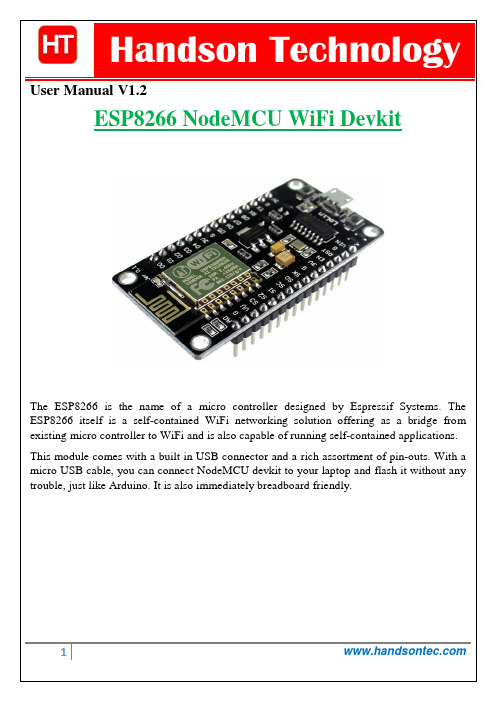
User Manual V1.2The ESP8266 is the name of a micro controller designed by Espressif Systems. The ESP8266 itself is a self-contained WiFi networking solution offering as a bridge from existing micro controller to WiFi and is also capable of running self-contained applications. This module comes with a built in USB connector and a rich assortment of pin-outs. With a micro USB cable, you can connect NodeMCU devkit to your laptop and flash it without any trouble, just like Arduino. It is also immediately breadboard friendly.Table of Contents1. Specification: (3)2. Pin Definition: (3)3. Using Arduino IDE (3)3.1 Install the Arduino IDE 1.6.4 or greater (4)3.2 Install the ESP8266 Board Package (4)3.3 Setup ESP8266 Support (5)3.4 Blink Test (7)3.5 Connecting via WiFi (9)4. Flashing NodeMCU Firmware on the ESP8266 using Windows (12)4.1 Parts Required: (12)4.2 Pin Assignment: (12)4.3 Wiring: (13)4.4 Downloading NodeMCU Flasher for Windows (13)4.5 Flashing your ESP8266 using Windows (13)5. Getting Started with the ESPlorer IDE (15)5.1 Installing ESPlorer (15)5.2 Schematics (18)5.3 Writing Your Lua Script (18)6. NodeMCU GPIO for Lua (22)7. Web Resources: (22)ing Arduino IDEClick ‘File’ -> ‘Preferences’ to access this panel. Next, use the Board manager to install the ESP8266 package.Click ‘Tools’ -> ‘Board:’ -> ‘Board Manager…’ to access this panel.Scroll down to ‘ esp8266 by ESP8266 Community ’ and click “Install” button to install the ESP8266 library package. Once installation completed, close and re-open Arduino IDE for ESP8266 library to take effect.Setup ESP8266 SupportWhen you've restarted Arduino IDE, select ‘Generic ESP8266 Module’ from the ‘Tools’ -> ‘Board:’ dropdown menu. Select 80 MHz as the CPU frequency (you can try 160 MHz overclock later)Find out which Com Port is assign for CH340 Select the correct Com Port as indicated on ‘Device Manager” Note: if this is your first time using CH340 “ USB-to-Serial ” interface, please install the driver first before proceed the above Com Port setting. The CH340 driver can be download from the below site:Once the ESP board is in bootload mode, upload the sketch via the IDE, Figure 3-2.Figure3-1: Connection diagram for the blinking testFigure 3.2: Uploading the sketch to ESP8266 NodeMCU module.The sketch will start immediately - you'll see the LED blinking. Hooray!Connecting via WiFiOK once you've got the LED blinking, let’s go straight to the fun part, connecting to a webserver. Create a new sketchconst char* host ="";void setup(){Serial.begin(115200);delay(100);// We start by connecting to a WiFi networkSerial.println();Serial.println();Serial.print("Connecting to ");Serial.println(ssid);WiFi.begin(ssid, password);while(WiFi.status()!= WL_CONNECTED){delay(500);Serial.print(".");}Serial.println("");Serial.println("WiFi connected");Serial.println("IP address: ");Serial.println(WiFi.localIP());}int value =0;void loop(){delay(5000);++value;Serial.print("connecting to ");Serial.println(host);// Use WiFiClient class to create TCP connectionsWiFiClient client;const int httpPort =80;if(!client.connect(host, httpPort)){Serial.println("connection failed");return;}// We now create a URI for the requestString url ="/projects/index.html";Serial.print("Requesting URL: ");Serial.println(url);// This will send the request to the serverclient.print(String("GET ")+ url +" HTTP/1.1\r\n"+"Host: "+ host +"\r\n"+"Connection: close\r\n\r\n");delay(500);// Read all the lines of the reply from server and print them to Serial while(client.available()){String line = client.readStringUntil('\r');Serial.print(line);}Serial.println();Serial.println("closing connection");}That's it, pretty easy right ! This section is just to get you started and test out your module.ESP8266 Module Breadboard Friendly with Header ConnectorESP8266 Module Breadboard FriendlyPL2303HX USB-UART Converter CableSome Male-to-Female Jumper WiresESP8266 Pin DescriptionCH_PD Pull high, connect to Vcc +3.3VVcc Power Supply +3.3VTXD Connect to RXD (white) of PL2303HX USB-Serial converter cable RXD Connect to TXD (Green) of PL2303HX USB-Serial converter cable GPIO0 Pull low, connect to GND pinGND Power Supply groundPress the button “Flash” and it should start the flashing process immediately, showing the Module MAC address if After finishing this flashing process, it should appear a green circle with a check icon at lower left corner.Your ESP8266 module is now loaded with NodeMCU firmware.Here’s a rundown of the features the ESPlorer IDE includes:Syntax highlighting LUA and Python code.Code editor color themes: default, dark, Eclipse, IDEA, Visual Studio.Undo/Redo editors features.Code Autocomplete (Ctrl+Space).Below the Code Window, you have 12 buttons that offer you all the functions you could possible need to interact with your ESP8266. Here’s the ones you’ll use most: “Save to ESP” and “Send to ESP”.5.3 Writing Your Lua ScriptBelow is your script to blink an LED.lighton=0pin=4gpio.mode(pin,gpio.OUTPUT)Right now you don’t need to worry how this code works, but how you can upload it to your ESP8266.Look at the top right corner of your ESPlorer IDE and follow these instructions: Press the Refresh button.Select the COM port for your FTDI programmer.Select your baudrate.Click Open.Copy your Lua script to the code window (as you can see in the Figure below):Congratulations, you’ve made it! The blue LED at the upper right corner should be blinking every 2 seconds!6. NodeMCU GPIO for LuaThe GPIO(General Purpose Input/Output) allows us to access to pins of ESP8266 , all the pins of ESP8266 accessed using the command GPIO, all the access is based on the I/O index number on the NoddMCU dev kits, not the internal GPIO pin, for example, the pin ‘D7’ on the NodeMCU dev kit is mapped to the internal GPIO pin 13, if you want to turn ‘High’ or ‘Low’ that particular pin you need to called the pin number ‘7’, not the internal GPIO of the pin. When you are programming with generic ESP8266 this confusion will arise which pin needs to be called during programming, if you are using NodeMCU devkit, it has come prepared for working with Lua interpreter which can easily program by looking the pin names associated on the Lua board. If you are using generic ESP8266 device or any other vendor boards please refer to the table below to know which IO index is associated to the internal GPIO of ESP8266.Nodemcu dev kit ESP8266 Pin Nodemcu devkitESP8266 PinD0 GPIO16 D7 GPIO13D1 GPIO5 D8 GPIO15D2 GPIO4 D9 GPIO3D3 GPIO0 D10 GPIO1D4 GPIO2 D11 GPIO9D5 GPIO14 D12 GPIO10D6 GPIO12D0 or GPIO16 can be used only as a read and write pin, no other options like PWM/I2C are supported by this pin.In our example in chapter 5 on blinking the blue LED, the blue LED in connected to GPIO2, it is defined as Pin4 (D4) in Lua script.7. Web Resources:•ESP8266 Lua Nodemcu WIFI Module•ESP8266 Breadboard Friendly Module•ESP8266 Remote Serial WIFI Module•PL2303HX USB-UART Converter Cable。
- 1、下载文档前请自行甄别文档内容的完整性,平台不提供额外的编辑、内容补充、找答案等附加服务。
- 2、"仅部分预览"的文档,不可在线预览部分如存在完整性等问题,可反馈申请退款(可完整预览的文档不适用该条件!)。
- 3、如文档侵犯您的权益,请联系客服反馈,我们会尽快为您处理(人工客服工作时间:9:00-18:30)。
ESP8266 WiFi模块用户手册目录术语和缩写 ................................................................................................................ 错误!未定义书签。
1. 产品简介 .................................................................................................................... 错误!未定义书签。
. 概述 .................................................................................................................... 错误!未定义书签。
产品特性 .................................................................................................... 错误!未定义书签。
模块封装 .................................................................................................... 错误!未定义书签。
模块基本参数 ............................................................................................ 错误!未定义书签。
. 硬件介绍 ............................................................................................................ 错误!未定义书签。
. 功耗 .................................................................................................................... 错误!未定义书签。
. 射频指标 ............................................................................................................ 错误!未定义书签。
. 尺寸 .................................................................................................................... 错误!未定义书签。
. WiFi 天线........................................................................................................... 错误!未定义书签。
. 推荐炉温曲线 .................................................................................................... 错误!未定义书签。
2. 功能描述 .................................................................................................................... 错误!未定义书签。
. 主要功能 ............................................................................................................ 错误!未定义书签。
. 工作模式 ............................................................................................................ 错误!未定义书签。
. 应用领域 ............................................................................................................ 错误!未定义书签。
. AiCloud ................................................................................................................ 错误!未定义书签。
3. 全功能测试版介绍 .................................................................................................... 错误!未定义书签。
. 测试步骤 ............................................................................................................ 错误!未定义书签。
. 基础AT指令 ...................................................................................................... 错误!未定义书签。
测试AT ................................................................................................................... 错误!未定义书签。
. WiFi功能AT指令.............................................................................................. 错误!未定义书签。
选择WiFi应用模式:AT+CWMODE ....................................................................... 错误!未定义书签。
列出当前可用接入点:AT+CWLAP .............................................................. 错误!未定义书签。
加入接入点:AT+CWJAP ............................................................................................ 错误!未定义书签。
退出接入点:AT+CWQAP........................................................................................... 错误!未定义书签。
设置AP模式下的参数:AT+CWSAP ........................................................... 错误!未定义书签。
. TCPIP AT指令 ..................................................................................................... 错误!未定义书签。
建立TCP/UDP连接:AT+CIPSTART ........................................................... 错误!未定义书签。
获得TCP/UDP连接状态:AT+CIPSTATUS ................................................. 错误!未定义书签。
启动多连接:AT+CIPMUX ......................................................................... 错误!未定义书签。
发送数据:AT+CIPSEND ............................................................................. 错误!未定义书签。
关闭TCP/UDP连接:AT+CIPCLOSE ........................................................... 错误!未定义书签。
获取本地IP地址:AT+CIFSR ..................................................................... 错误!未定义书签。
配置为服务器: ........................................................................................ 错误!未定义书签。
选择TCPIP应用模式:AT+CIPMODE ........................................................ 错误!未定义书签。
设置服务器主动断开的超时时间:AT+CIPSTO ....................................... 错误!未定义书签。
设置波特率:AT+CIOBAUD ..................................................................... 错误!未定义书签。
4. 产品试用 .................................................................................................................... 错误!未定义书签。
