有毒气体检测仪(霍尼韦尔PHD6)
gastech PHD6 使用说明书

H2S
0-200 PPM 1 PPM
35 100 15 1** <20sec
PH3 0-20 0.1 PPM 0.3
0.3
Duo-Tox CO
0-999 PPM 1 PPM
Duo-Tox H2S
0-200 PPM 1 PPM
10 20 100 35 <20sec
15 10 <20sec
HCN 0-100 0.2 PPM 2.4 4.7 4.7 4.7
PID sensor option
PID sensor monitors for hundreds of known VOCs.
Electrochemical sensor options
Choose from 13 different electrochemical toxic gas sensors.
PHD6
gas detection designed for support
SPECIFICATIONS Specifications subject to change without notice
5 Sensor ports and 18 sensor choices
With 18 sensor choices, including PID, IR-CO2, IR-CH4, conventional LEL, oxygen and 15 different toxic gas sensors including Duo-Tox, the PhD6 can be configured for just about any use.
Li-Ion battery pack runs for up to 22 hrs. Alkaline battery packs also available.
BW Technologies by Honeywell 的气体检测仪说明书

Certificate of Compliance Certificate:1730355 Master Contract: 157918 Project:70024685 Date Issued: April 05, 2015Issued to: BW Technologies by Honeywell2840 2nd Ave SECalgary, Alberta T2A 7X9CANADAAttention: Stephen Uliasz The products listed below are eligible to bear the CSA Mark shownwith adjacent indicators 'C' and 'US' for Canada and US or with adjacent indicator 'US' for US only or without either indicator for Canada only.Issued by: Gary BendenGary BendenPRODUCTS4828 01 - SIGNAL APPLIANCES - Combustible Gas Detection Instruments - For Hazardous Locations 4828 02 - SIGNAL APPLIANCES - Toxic Gas Detection Instruments - For Hazardous Locations4828 81 - SIGNAL APPLIANCES - Combustible Gas Detection Instruments - For Hazardous Locations -Certified to U.S. Standards4828 82 - SIGNAL APPLIANCES - Toxic Gas Detection Instruments - For Hazardous Locations -Certified to U.S. StandardsClass I, Division 1; Groups A, B, C and/or D; T4GasAlertMicroClip XT Portable Gas Detector, MC2-XWHM-a-bb-cc Temperature Code T4 @ -20°C ≤ Ta ≤ +58°C; Multi-gas detectors for monitoring up to four gasses simultaneously and continuously i.e. Oxygen[deficiency/enrichment], Combustibles, Carbon Monoxide and Hydrogen sulphide ; Intrinsically Safe when powered by a non user replaceable Narada Lithium Polymer battery Part Number: NL503759.GasAlertMicroClip XL Portable Gas Detector, MCXL-XWHM-a-bb Temperature Code T4 @ -20°C ≤ Ta ≤ +50°C; Multi-gas detectors for monitoring up to four gasses simultaneously and continuously i.e. Oxygen[deficiency/enrichment], Combustibles, Carbon Monoxide and Hydrogen sulphide ; Intrinsically Safe when powered by a non user replaceable Narada Lithium Polymer battery Part Number: NLP883759LT20.Certificate:1730355 Project:70024685Master Contract:157918 Date Issued:April 05, 2015GasAlertMicroClip X3 Portable Gas Detector, MCX3-XWHM-a-bb Temperature Code T4 @ -20°C ≤ Ta ≤+50°C; Multi-gas detectors for monitoring up to four gasses simultaneously and continuously i.e. Oxygen [deficiency/enrichment], Combustibles, Carbon Monoxide and Hydrogen sulphide ; Intrinsically Safe when powered by a non user replaceable Narada Lithium Polymer battery Part Number: NLP883759LT20.APPLICABLE REQUIREMENTSCSA Standard C22.2 No. 0-2010 General Requirements Canadian Electrical Code Part II.CSA Standard C22.2 No. 152-M1984 Combustible Gas Detection InstrumentsCSA Standard C22.2 No. 157-92 Intrinsically Safe and Non-Incendive Equipment for Use in HazardousLocationsUL Standard 913, Seventh Edition Intrinsically Safe Apparatus and Associated Apparatus for use in ClassI, II, III, Division 1, Hazardous (Classified) LocationsANSI/ISA-12.13.01-2000 Performance Requirements for Combustible Gas DetectorsMARKINGSThe manufacturer is required to apply the following markings:•Products shall be marked with the markings specified by the particular product standard.•Products certified for Canada shall have all Caution and Warning markings in both English and French. Additional bilingual markings not covered by the product standard(s) may be required by the Authorities Having Jurisdiction. It is the responsibility of the manufacturer to provide and apply these additional markings, where applicable, in accordance with the requirements of those authorities.Marking On Main Unit:(1)Submittor's name, trademark, or the CSA file number (adjacent the CSA Mark).(2)Catalogue / Model designation.(3)Date code / Serial number traceable to month and year of manufacture.(4)Hazardous Location designations, Class I, Division 1; Groups A, B, C and/or D; T4 (May beabbreviated Cl. I Gr. A, B, C, D T4).(5)The symbol “Exia” and the words “Intrinsically Safe”, and “Sécurité Intrinsèque”.(6)“Read and understand manual” and “Lire et comprendre le manuel”.(7)C22.2 No 152, S12.13.(8)The CSA Mark with or without the “c” and/or “us” qualifiers.(9)Temperature Code Rating, T4.(10)Ambient Temperature Range -20°C ≤ Ta ≤ +58°C, or -20°C ≤ Ta ≤ +50°C, as applicable.(11)Optional Hazardous Location designations, Class I, Zone 0, IIC.(12)WARNING: Battery must be charged in a non-hazardous area and may only be replaced by themanufacturer. (May be in user manual).(13)WARNING: SUBSTITUTION OF COMPONENTS MAY IMPAIR INTRINSIC SAFETY. (May bein User Manual).Supplement to Certificate of ComplianceCertificate:1730355 Master Contract:157918The products listed, including the latest revision described below,are eligible to be marked in accordance with the referenced Certificate.Product Certification HistoryProject Date Description70024685 Apr 5 2015 Update of Report 1730355 to include addition of a new modelGasAlertMicroClip X3 and additionally include a crystal component changeto the GasAlertMicroClip XT/XL.70018883 Feb 27 2015 Update to Report 1730355 to include firmware change for modelsGasAlertMicroClip XT and XL.2710384 Jul 21 2014 Update to report 1730355 to add new model GasAlertMicroClip XL;MCXL-XWHM-a-bb; Temperature Code T4 @ -20°C # Ta # +50°C;Powered by Part Number: NLP883759LT20.2689722 Feb 28 2014 Update report to cover removing GasAlertMicroClip, Lithium Polymerbatteries (Varta PLF 503759, PLF 503759D, PLF 503759C, BYD SL503759), Micropel 40-CITY TECHNOLOGY; revising drawings to includefuse, resistors and transistors changes.2618343 Jul 25 2013 HAZ 130139: Update to Report1730355 to cover revised firmware (rev.40F).2451746 Aug 31 2011 Update report 1730355 to add test confirmation for revised internal lowbattery alarm operating parameter.2305825 Dec 15 2010 Update to report 1730355 to include new battery and alternate O2 sensorwhich results in the creation of the Gas Alert Micro Clip XT.2249935 Jan 12 2010 Update to Report 1730355 to include alternate vibrator motor.2102246 Nov 28 2008 Update to report 173055 to add new battery.2033112 May 1 2008 Update of report 1730355 to allow the product to be built at BWT Calgaryand at Systems Sensor de Mexico in Juarez.1888493 Mar 22 2007 Update to Report 1730355 to include new battery1816037 Oct 6 2006 Update to Report 1730355 to include brown out chip, MicroPel 75 sensorand new battery (includes performance testing).1773170 Apr 21 2006 Update to report 1730355 to correct order number, upgrade firmware and addalternate components1730355 Dec 8 2005 GasAlertMicroClip Portable Gas Detector for use in Hazardous Locations。
霍尼艾格在线VOC气体检测仪

产品描述在线式VOC气体检测仪HNAG1000-VOC适用于各种环境中的二甲苯体浓度和泄露实时准确检测,采用进口电化学传感器和微控制器技术. 响应速度快,测量精度高,稳定性和重复性好等优点. 防爆接线方式适用于各种危险场所并兼容各种控制报警器 PLC DCS等控制系统可以同时实现现场报警预警 4-20mA标准信号输出继电器开关量输出; 完美显示各项技术指标和气体浓度值; 同时具有多种极强的电路保护功能有效防止各种人为因素不可控因素导致的仪器损坏;产品特点●本安电路设计,防爆认证,二级防雷、防静电,防雷和防静电能力超过国家标准,抗高强度脉冲浪涌电流冲击。
高可靠性和稳定性。
●符合EMI、EMC标准,通过国标测试及CMC计量器具许可认证。
GB 3836.1—2010 《爆炸性气体环境用电气设备通用要求》GB 3836.2—2010 《爆炸性气体环境用电气设备隔爆型“d”》GB 3836.4—2010 《爆炸性气体环境用电气设备本质安全型“i”》●标准总线RS485和4~20mA标准信号同时输出,1组继电器开关量输出,可选频率输出200-1000Hz 、Hart协议信号、1~5V输出、无线传输(10-50公里或不限距离)。
可以有线或无线远程实时监控,将数据上传到手机或通过局域网、互联网传输到环保局、其他监控中心、监控设备、监控电脑,通过免费上位机软件或气体报警控制器实时监控现场的浓度。
●兼容各种二次表、数据采集模块、PLC、DCS系统,可直接驱动电磁阀、风机、报警器等设备,也可以通过驱动中间继电器来驱动大功率设备。
●标配红外遥控器,可以实现在危险场合免开盖操作,比如:修改报警点、浓度校准、零点校准、消音、恢复出厂、进入菜单、●2.5寸高清彩屏(TF)显示实时浓度、温度、湿度、●自动跟踪零点防止漂移,温度补偿、多级校准,能同时符合国标和各个地区的地方、省级计量局标准产品参数。
霍尼韦尔气体侦测器设置气体浓度单位
霍尼韦尔气体侦测器设置气体浓度单位
摘要:
1.霍尼韦尔气体检测仪的概述
2.气体浓度单位的介绍
3.气体浓度单位之间的换算关系
4.气体检测仪在安全监控中的应用
正文:
霍尼韦尔气体检测仪是一种用于检测环境中气体浓度的设备,具有广泛的应用。
在工业生产、环境监测、安全防护等领域都能看到它的身影。
气体检测仪能够检测的气体种类繁多,包括可燃性气体、有毒气体、氧气等。
气体浓度单位是描述气体在空气中所占体积比例的一种衡量标准。
常见的气体浓度单位有PPM、mgm3、%VOL 和%LEL。
PPM 表示百万分之体积,是气体检测仪的常用浓度单位。
mgm3 表示气体的质量浓度单位,mgm3 和PPM 之间有换算公式。
%VOL 表示体积浓度,和PPM 表示的意义同样,只不过表示高浓度时使用此单位。
%LEL 表示气体的爆炸下限单位,当可燃性气体浓度达到100%LEL 时,遇到电火花就会发生爆炸。
不同的气体的爆炸下限值不一样,例如氢气4%VOL100%LEL,甲烷5%VOL100%LEL。
PPM 和mgm3 之间的换算关系为(PPM22.4 乘以mgm3,再除以气体分子量)。
在安全监控中,气体检测仪起到了重要的作用。
例如,在化工厂、石油化工、燃气站等易燃易爆场所,气体检测仪能够实时监测可燃性气体的浓度,一旦浓度超标,就能及时发出警报,避免事故的发生。
此外,气体检测仪还可以
用于监测室内空气质量,保障人们的身体健康。
总的来说,霍尼韦尔气体检测仪在设置气体浓度单位方面具有丰富的经验和技术积累。
Midas中文版资料
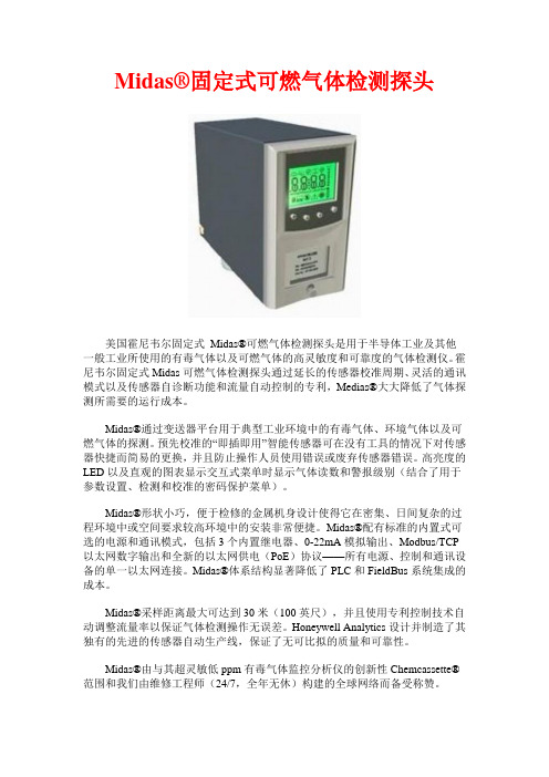
Midas®固定式可燃气体检测探头美国霍尼韦尔固定式Midas®可燃气体检测探头是用于半导体工业及其他一般工业所使用的有毒气体以及可燃气体的高灵敏度和可靠度的气体检测仪。
霍尼韦尔固定式Midas可燃气体检测探头通过延长的传感器校准周期、灵活的通讯模式以及传感器自诊断功能和流量自动控制的专利,Medias®大大降低了气体探测所需要的运行成本。
Midas®通过变送器平台用于典型工业环境中的有毒气体、环境气体以及可燃气体的探测。
预先校准的“即插即用”智能传感器可在没有工具的情况下对传感器快捷而简易的更换,并且防止操作人员使用错误或废弃传感器错误。
高亮度的LED以及直观的图表显示交互式菜单时显示气体读数和警报级别(结合了用于参数设置、检测和校准的密码保护菜单)。
Midas®形状小巧,便于检修的金属机身设计使得它在密集、日间复杂的过程环境中或空间要求较高环境中的安装非常便捷。
Midas®配有标准的内置式可选的电源和通讯模式,包括3个内置继电器、0-22mA模拟输出、Modbus/TCP 以太网数字输出和全新的以太网供电(PoE)协议——所有电源、控制和通讯设备的单一以太网连接。
Midas®体系结构显著降低了PLC和FieldBus系统集成的成本。
Midas®采样距离最大可达到30米(100英尺),并且使用专利控制技术自动调整流量率以保证气体检测操作无误差。
Honeywell Analytics设计并制造了其独有的先进的传感器自动生产线,保证了无可比拟的质量和可靠性。
Midas®由与其超灵敏低ppm有毒气体监控分析仪的创新性Chemcassette®范围和我们由维修工程师(24/7,全年无休)构建的全球网络而备受称赞。
仪器特点:•可用于40多种气体,并带有两年延长保质期•带有内置“电子标定”证书的智能传感器夹头•内置1、2级警报以及故障用继电器•以太网供电(PoE)通讯和供电平台•键盘接口和远程网络浏览器接口•连接到任意变送器的热裂解器和LonWorks接口可选模块•密码保护菜单管理功能用于维护系统完整性•高亮度LED和直观图标显示、超大背光式LCD显示屏•工厂校准的传感器可减少频繁的真实气体测试•带有故障和状态报告的格力的0-22mA模拟输出•ModBus/TCP以太网通讯方式可便捷地连接到控制和报警系统以达到控制连接以及进行服务•可到30米取样距离的强有力的采样泵系统(2年使用寿命)•交互式训练模拟器工具•CE标记的用于全面抗电磁干扰•Reflex®传感器工作状态检查以改善探测器工作安全可靠性•TempraSure®TM温度补偿基数(视情况而定)•浏览传感器历史的状态记录•确认气体泄漏以避免误报警的专利技术可探测气体:仪器参数:•发送器尺寸(带有传感器的机组):120毫米高,63毫米宽,150毫米厚•发送器重量(带有传感器的机组):0.8千克•(低温版)热解器尺寸:70毫米高,63毫米宽,83毫米厚•(低温版)热解器重量:0.41千克•(高温版)热解器尺寸:113毫米高,101毫米宽,140毫米厚•(高温版)热解器重量:1.25千克•操作电压:24V DC 标称+/-10%•以太网供电操作电压:36-57VDC(经由PoE),48V DC 标称•发送器部件功耗:约5.0瓦•带有热解器(可选件)的功耗:小于12.95瓦•可视类输出:警报、电源和故障等以及带有气体读数和结果的背光液晶显示器•继电器输出:分别用于警报1、警报2和故障的3个继电器,额定值:1.0A@30VDC或0.5A@125VAC;可配置的NO(常开)或NC(常闭),上锁或未上锁•模拟输出:2路绝缘的0-22mA•数字通讯:标准,ModBus/TCP以太网;以太网供电(PoE),可选LonWorks •服务端口:RS 232C/PPP协议•欧洲认证:CE标记;符合EN 50270:1990(类型2)和EN 55011:2000•环境认证:经ETL审核批示UL 61010B和CSA-C22.2 No. 1010.1-92•性能认证:设计符合UL 2075(未决的2004)•电器认证:IEEE 802.3af-2003•流率:500毫升/分钟•运输时间:最大2-30秒•性能:LDL•取样管道长度:长达30米(100英尺),带有FEP管道,具体取决于气体类型•取样环境点监测:推荐在线空气过滤器•取样排气管长度:长达30米(100英尺)•样品管道:6.35毫米外径(1/4英寸)×3.18毫米(1/8英寸),FEP,最长30米(100英尺),具体取决于气体类型•排气管道:6.35毫米外径(1/4英寸)×3.18毫米(1/8英寸),FEP,30米(100英尺)•带有传感器的机组的操作温度:0-40摄氏度•4-20mA/DC电源/继电器的接线要求:最大14AWG•数字化接线要求:屏蔽CAT 5电缆或等同物,RJ 45连接器•仪器显示器及显示介面:带分离测量部件、流率条形图和其它标象指示器的4位字母数字显示屏;4按钮薄膜键盘•远程界面:可透过以太网或其它总线系统访问的PC/PDA网络浏览器•发送器部件保修:1年•传感器夹头保修:标准,1年;带有扩展保修项目:2年•帮浦的预期寿命:大于2年•安装方法:使用在后机身上预先钻好的两个孔进行墙面安装•安装材料:带油漆罩面的钢铁盒氟F20-4.0ppm锗烷GeH40-0.8ppm 六氟丁乙烯C4F60-40ppm 氢(%爆炸下限(LEL))H20-100% LEL 氢(ppm)H20-1000ppm溴化氢HBr0-8.0ppm氯化氢HCl0-8.0ppm氰化氢HCN0-20ppm氟化氢HF0-12ppm 氟化氢(低浓度的)HF0-2.0ppm硫化氢H2S0-40ppm 硫化氢(高浓度的)H2S0-100ppm 甲烷(%爆炸下限(LEL)) CH40-100% LEL 甲基氟CH3F0-60ppm二氧化氮NO20-12ppm一氧化氮NO0-100ppm三氟化氮NF30-40ppm八氟环戊烯C5F80-40ppm氧气能力&缺氧O20-25% vol臭氧O30-0.4ppm磷化氢PH30-1.2ppm氢氧化磷POH30-0.4ppm硅烷SiH40-20ppm 硅烷(低浓度的)SiH40-2.0ppm 二氧化硫SO20-8.0ppm六氟化硫SF60-8000pm四氟化硫SF40-0.4ppm正硅酸乙酯TEOS0-40ppm六氟化钨WF60-12ppm 六氟化钨(低浓度的)WF60-2.0ppmTiger2015-01-22。
霍尼韦尔6df6g压力传感器说明书
霍尼韦尔6df6g压力传感器说明书【实用版】目录1.霍尼韦尔压力传感器概述2.霍尼韦尔压力传感器的性能特点3.霍尼韦尔压力传感器的应用领域4.霍尼韦尔压力传感器的使用方法与注意事项5.霍尼韦尔压力传感器的优缺点分析正文一、霍尼韦尔压力传感器概述霍尼韦尔压力传感器是一款由霍尼韦尔公司生产的高品质压力传感器,具有高精度、高稳定性、高可靠性等特点。
它可以将压力信号转化为标准电信号,用于测量流体、气体等介质的压力变化,广泛应用于工业、汽车、医疗、航空等领域。
二、霍尼韦尔压力传感器的性能特点1.高精度:霍尼韦尔压力传感器具有很高的测量精度,可以准确地测量压力变化,满足各种应用场景的需求。
2.高稳定性:霍尼韦尔压力传感器具有很好的稳定性,可以在长时间内保持测量精度,减少误差。
3.高可靠性:霍尼韦尔压力传感器具有较高的可靠性,可以在恶劣的环境下正常工作,降低故障率。
4.响应速度快:霍尼韦尔压力传感器具有较快的响应速度,可以实时测量压力变化,提高系统的响应速度。
5.抗干扰能力强:霍尼韦尔压力传感器具有较强的抗干扰能力,可以有效抵抗各种干扰信号,保证测量结果的准确性。
三、霍尼韦尔压力传感器的应用领域霍尼韦尔压力传感器广泛应用于工业、汽车、医疗、航空等领域,具体包括:1.工业自动化:用于流程控制、生产过程监测、设备运行状态检测等。
2.汽车行业:用于汽车发动机控制系统、刹车系统、油压检测等。
3.医疗行业:用于医疗设备、监护仪、呼吸机等。
4.航空航天:用于飞行控制系统、飞机发动机控制等。
四、霍尼韦尔压力传感器的使用方法与注意事项1.使用方法:将霍尼韦尔压力传感器与被测介质相连接,通过信号线连接到控制系统,即可实现压力信号的测量。
2.注意事项:(1)在安装时,应确保传感器与被测介质的接触良好,避免出现漏气现象。
(2)使用过程中,应注意保护传感器,防止受到机械损伤或腐蚀。
(3)在接线时,应确保接线牢固,避免线松动造成信号丢失。
霍尼韦尔XT-4四合一检测仪参数

霍尼韦尔XT-4四合一检测仪参数
霍尼韦尔BW XT-4气体检测仪
一、产品介绍
坚固耐用的GAMAX-XT可以可靠地监测最多四种有毒气体,它将直观的单按钮界面操作与一体化采样泵结合起来。
防篡改、用户可调节选项允许自定义该仪器,以适合您的应用。
采用新的智能泵技术后,进入受限空间和远程采样的容易程度是大的。
降低泵阻塞的几率,并提高了远程采样结果的精度。
二、产品参数
1、测量范围: H2S:0-200ppm CO:0-1000ppm O2:0-30.0%VOL 可燃气体:0-100%LEL
2、尺寸重量:13.1×7.0×15.2厘米,316克
3、环境条件:温度 -20—50℃、湿度10—100%相对湿度(非凝结)
4、报警:视觉、振动、声音(95dB),低限、高限、STEL、TWA、超限,电量不足、泵。
5、测试:视听警报在启动仪器时激活,视听警报在传感器故障时、电池电量不足时、泵和电路故障时发出警报。
6、电池寿命:0℃时13小时,20℃时10小时,6小时即可充满电。
7、泵吸:20米处提取样本。
8、等级:IP66/67
三、产品特点
1、LCD可不间断的实时显示气体浓度
2、小巧而轻便的设计,佩戴感觉很舒适
3、防水
4、简单的自动校准程序
5、启动时对传感器、电池状态、线路完整性以及声光报警进行全功能自检
6、明亮的广角可视警报光柱
7、内置式防震外罩
聚创环保为您提供全面的技术支持和完善的售后服务!。
气体检测仪说明书- Honeywell Analytics 气体检测仪说明书- GasAlertMi

H2S, CO, O2, LELMulti-gas made simpleThe easy to wear, slim and compact GasAlertMicroClip providesaffordable protection from atmospheric gas hazards and extendedbattery life, especially in cold weather. The GasAlertMicroClip featuresvisual compliance at a glance with the flashing, green IntelliFlash™. Easyone-button operation reduces training time and lets workers focus onthe job at hand. For simple, cost-effective management of your records,calibration and bump testing, choose BW’s MicroDock II automatic testand calibration system and Fleet Manager II software.Meets ACGIH 1 ppm H2S TWA recommendations.Visit to download the latest Fleet Manager IIupdate.Standard Package Contents• Detector complete with specified sensor(s), stainless steel alligator clipand concussion-proof housing• Rechargeable battery• Wall outlet charging adaptor• Calibration/test cap and hose• Manual• Multi-language CD manualGeneral SpecificationsGasAlertMicroClip XL GasAlertMicroClip X3Size 4.4 x 2.4 x 1.2 in. /11.3 x 6.0 x 3.1 cm 4.4 x 2.4 x 1.2 in. / 11.3 x 6.0 x 3.1 cmWeight 6.7 oz. / 190 g 6.3 oz. / 179 g Temperature-4 to +122°F / -20 to +50°CTypical battery life18 hours (recharges in less than 6 hours)Note: Battery is guaranteed to have 12 hour runtime during warranty periodunder normal operating temperature of 4°F / -20°C to 122°F / 50°C. Ingress Protection IP68Certifications andapprovals n Class I, Div. 1, Gr. A, B, C, DATEX:X g II 1 GEx ia IIC T4 GaIECEx:Ex ia IIC T4 GaX: European ConformityWarranty Full two-year (GasAlertMicroClip XL) orthree-year (GasAlertMicroClip X3) warranty including all sensorsOrder NumberGasAlertMicroClip 4-Gas Detector GasAlertMicroClip XL GasAlertMicroClip X3GasAlertMicroClip 3-Gas Detector GasAlertMicroClip XL GasAlertMicroClip X3GasAlertMicroClip 2-Gas Detector GasAlertMicroClip XL GasAlertMicroClip X3GasAlertMicroClip 1-Gas Detector GasAlertMicroClip XL GasAlertMicroClip X3Note: To order a unit with black housing, change order number component "-Y-" to "-B-".GasAlertMicroClip Region CodesGas LegendMicroDock IIAutomatic test and calibrationstation (see MicroDock II sectionfor additional information)Confined Space KitOrder NumberCarrying & Protective Accessories Order NumberSampling & Testing EquipmentOrder NumberNote: For complete list of Sampling & Testing Equipment, please refer to the full Price List or contact Honeywell Analytics.Power Options and Spares Order Number *For regions outside North America replace “-NA” with: “-EU” for Europe, “-UK” for United Kingdom and “-AU” for Australia/China.Deluxe Confined Space KitMC-CK-DLOrder detector and calibration gas separately.Test CapMC-TC-1Auxiliary Filter KitMC-AF-K1Easily attaches in the fieldto protect the internal filterManual Aspirator Pump KitMC-AS01For remote sampling; complete with probe,hose, aspirator pump and adaptor capBlack Leather PVC CaseMC2-LC-1Datalogging AccessoriesOrder NumberMicroDock IIOrder NumberReplacement Sensor ScreensOrder NumberReplacement SensorsOrder NumberFor a full list of calibration and testing equipment, please refer to the full Price List or contact Honeywell Analytics.IR Connectivity KitGA-USB1-IRUse for data download andinstrument set-up optionsVehicle Power Adaptor 12-24 V dcGA-VPA-1Direct-Wire Power Adaptor 12-24 V dcGA-PA-3Multi-Unit Power AdaptorGA-PA-1-MC5-NA*Simultaneously charges five detectorsMulti-Unit Cradle ChargerMC2-C01-MC5Simultaneously charges five detectorsNote: Please refer to the instrument’s documentation (shipped with the product or available at ) for complete instructions on common service procedures. Improper servicing or maintenance may affect warranty eligibility. Honeywell assumes no liability for damages resulting from improper servicing or maintenance.LegendService PartsOrder Number Note: Please refer to the instrument’s documentation (shipped with the product or available at ) for complete instructions on common service procedures. Improper servicing or maintenance may affect warranty eligibility. Honeywell assumes no liability for damages resulting from improper servicing or maintenance.How to Replace a Sensor1. With detector OFF , use No. 1 Phillips screwdriver to remove 6screws from back enclosure (E)2. Lift back enclosure (E) straight up3. Use No. 1 Phillips screwdriver to remove 2 screws from backof PCB (D)4. Lift PCB (D) together with battery and sensors (C, G, H, I)straight up5. Remove sensors (C, G, or H) by sliding out or sensor (I) bypulling straight up from PCB (D)6. Insert new sensor (C, G, H, I) into PCB (D)7. Replace PCB (D) and 2 screws and hand-tighten until firm 8. Replace back enclosure (E)9. Replace 6 screws in back enclosure (E) andhand-tighten until firmHow to Replace the Sensor Screen1. With detector OFF , use No. 1 Phillips screwdriver to remove 6screws from back enclosure (E)2. Lift back enclosure (E) straight up3. Use No. 1 Phillips screwdriver to remove 2 screws from backof PCB (D)4. Lift PCB (D) together with battery and sensors (C, G, H, I)straight up5. Remove sensor screen (J) from front enclosure (B)6. Insert new sensor screen (J) into front enclosure (B)7. Replace PCB (D) and 2 screws and hand-tighten until firm 8. Replace back enclosure (E)9. Replace 6 screws in back enclosure (E) andhand-tighten until firm。
霍尼韦尔氢气检测仪安全操作及保养规程

霍尼韦尔氢气检测仪安全操作及保养规程仪器简介
霍尼韦尔氢气检测仪是专门用于检测氢气浓度的仪器,其检测原理基于电化学传感器,可广泛用于氢燃料电池车、氢气气瓶、氢气发生器和实验室等领域。
安全操作
1.在操作前,必须保证仪器已充足充电或接入电源,并进行
自检后方可使用。
2.操作前要先查阅本使用手册,了解相关操作步骤及注意事
项。
3.打开仪器电源开关并等待一段时间后,待电池电量显示正
常后即可进行测量。
4.对于不同应用场景,选择不同的气体类型进行测量,如氢
气、氢气/二氧化碳。
5.检测仪的探头必须放置在测量范围内,根据测量需求选择
是否使用吸气管或延长探头。
6.检测时应尽量减少杂质干扰,如烟雾、污染物等。
7.检测过程中如发现异常情况,应立即停止操作并进行相关
维修或更换。
保养规程
1.使用完毕后,应关闭电源开关,尽量减少电池损耗。
2.检测仪使用后应定期进行维护及校准,建议一年一次或根
据使用频率进行调整。
3.检测仪外壳使用时应注意避免磨擦及碰撞,保持表面干净,
不使用时应放置于干燥通风处。
4.检测仪使用前应先查看是否有明显损坏或老化的零部件,
及时更换或修理。
5.电池使用寿命为2-3年,如发现电量衰减明显应及时更换
或充电。
6.探头使用寿命为12个月,如发现指示不准或无法读取应及
时更换探头。
7.请勿私自拆卸或改造检测仪,如需维修请联系相关售后服
务。
结语
以上就是霍尼韦尔氢气检测仪的安全操作及保养规程,使用者在使
用仪器时务必遵守相关规定,保证仪器的良好使用效果。
霍尼韦尔 侦测污染气体的指南书 ( 空气质量监测系统指南书 )说明书

This step-by-step guide describes set-up procedures to help provide a safe parking garage while minimizing energy costs associated with ventilation and heating.2In parking structures, CO and NO 2 are two of the most abundant airborne contaminants and poses significantsafety concerns. The CO and NO 2 levels must be controlled or ventilated when concentrations approach unsafe levels.Various gas monitors are available for use in parking structureapplications. The specifics of the design determine what type of monitor or monitoring system best suits the application. This detailed, easy-to-use guideline assists the design engineer in the selection of an optimal gas detection solution.Codes and StandardsStep 1: Determine the reason(s) why you want to detect the presence of carbon monoxide.• Safety: In any facility where people are working or the public and tenants may be active, there must be due diligence on the part of the owner to assure a safe breathing environment.• Economics: To provide fresh air in a facility where vehicles are present, a pre-determined air change per hour is required. This can be expensive for a number of reasons:1) The electrical energy required to run the fans can be high.2) The fans run continuously which incurs wear and shortens motor life.3) The frequency of required maintenance is higher for belt and lubrication services.4) The heat loss in a garage is higher with the high volume of air changes.• Aesthetics: In private facilities, the outside fan noise and loss of heat within the garage can affect tenant satisfaction.Step 3 : Building codes and carbon monoxide monitoring• International Mechanical Code - Section 403.5 Public garages - Mechanical ventilation systems for public garages are not required to operate continuously where the system is arranged to operate automatically upon detection of a concentration of carbon monoxide of 25 ppm by approved detection devices.• Uniform Building Code - Section 705 - In allparking garages…automatic CO sensing devices may be employed to modulate the ventilation system to maintain a maximum average of CO of 50 ppm during any eight-hour period, with a maximum average concentration not greater 200 ppm for a period not exceeding one hour…• State, municipal and other building codes - Most state, and local municipal buildingcodes recognize and recommend using carbon monoxide monitors in enclosed parking garages. If the building code in your area does not have any provisions for CO monitoring, do not forget that carbon monoxide is still a very dangerous gas to personal health and safety. Therefore, the use of common sense by design engineers is still the best “building code” to use.Step 2 : What the ASHRAE handbook says about carbon monoxide detection in parking garages:• “The operation of automobiles presents two concerns. The most serious is the emission of carbon monoxide, with its own risks.”• “The second concern is the presence of oil and gasoline fumes…the ventilation required to dilute carbon monoxide to acceptable levels will also control the other contaminants satisfactorily.”• “To conserve energy, fan systems should be controlled by carbon monoxide meters with multiple fan or variable speed stages for larger systems, if permitted by local codes. In multi-level parking garages or single-level structures of extensive area, independent fan systems, each under individual control, are recommended.”• “The ventilation system in parking garages, in general, moves large quantities of air throughlarge openings without extensive ductwork. These conditions, in addition to the highly reverberant nature of the space, contribute to high noiselevels.”The 301C is able to monitor up to 96 hardwired transmitters and has a series of relays which can activate alarms and/or ventilation equipment as required.• Carbon monoxide poisoning is a form of asphyxiation. Carbon monoxide combines with hemoglobin, the oxygen-carrying constituent of blood, 210 times more readily than does oxygen. Carboxyhemoglobin is then formed. Carbon monoxide lowers the oxygen carrying capacity of blood and interferes with necessary gaseous exchange functions.• Human health effects can vary significantly based on overall state of health, sex, age and weight.• Many studies have shown that the CO content in exhaust gases of individual vehicles varies greatly. This variation is caused by such factors as the age of the vehicle, carburetor adjustment or injector condition, quality of fuel, engine horsepower, level of maintenance, and differing driving habits of motorists.• Levels of carbon monoxide in garages vary depending on:1) Number of cars running2) Length of travel and operation time of cars in the garage3) Emission rate of vehicle4) Acceptable contaminant level within a given facility Sequence of OperationStep 5: Carbon monoxide alarm levels andrecommended sequence of operation• First alarm level:1) Set at low concentration. See Table 2 forrecommended low alarm level).2) Gas monitoring system shall be able to actuateexhaust fans and outside air intake devices tobring the carbon monoxide level down to anacceptable level.3) Optional: if the parking structure is equippedwith either two-speed fans or with a second setof fans, only the first speed of fans or the first setof fans should be actuated.• Second alarm level:1) Set at high concentration. See Table 2 forrecommended high alarm level).2) Ventilation equipment previously actuatedat low level in the parking garage shall remainoperational.3) Optional: if the parking structure is equippedwith either two-speed fans or with a second setof fans, they should be activated at full speed orall fans should be activated.4) Activation of strobe light (red) and horn mightbe required.5) People might be required to evacuate theparking garage.The E3Point utilizes cutting edge technology in orderto accurately and reliably monitor carbon monoxideand Nitrogen Dioxide (diesel fumes) levels.Step 7: Interlock of the mechanical ventilation with the carbon monoxide monitoring systemThe CO monitoring system shall activate the mechanical ventilation by using either:• Dry contacts through magnetic starters• Dry contacts through motor control center (MCC)• Dry contacts and/or analog outputs (4-20 mA) through the Building Management System (BMS)• Analog outputs (4-20 mA) modulating the speed of the fans through variable frequency drives (VFD)The carbon monoxide monitoring system must be capable of activating both the exhaust fan(s) and the air intake device(s) such as outside air louvers/ dampers and make up air unitsEquipment Selection and Location: Central Panel and Output ModuleStep 8: Monitoring System Selection• Stand-alone monitors: These are usually single points for smaller applications (small number of monitoring points). They are real-time reading with a limited amount of outputs and no moving parts (less maintenance).• Network monitoring system: These are for multiple sensing points usually being largerapplications. They are real-time reading withseveral programmable outputs and no movingparts (less maintenance)Step 9: Gas detection central panel and relaymodule• Must be located out of reach of the generalpublic.• Preferably located inside or close to the motorcontrol center or in connecting offices.• The controller shall allow programmable alarmlevels through relays.• Addressable transmitters are daisy-chainedthrough a RS-485 communication protocol to thecontroller.• The controller module and programming shouldbe accessible only by using the proper password.• Shall be capable of averaging / zoning.• Optional 4-20mA / digital input card to allow fan’scurrent sensor to be connected to the controller.Step 10: Self-test diagnostics withmalfunction warning• Not all monitors on the market offer thesefeatures.• These features insure protection at all times.• Checks operating status of the monitor itself.Step 11: Output signals• Alarm relay output: At least two are required (lowand high levels).• Failure relay output: Only one is required (indicatemonitor failure).• Analog output: provides one 4-20 mAper output sensor or provides the highestconcentration, the lowest concentration or theaverage concentration of CO for a group ofsensors (normally interlocked with The BuildingManagement System).Step 13: Quantity of sensors and plan locationThe quantity of sensors is determined by the following rules of thumb:1) The radius of coverage is 15.2 m (50 feet) per carbon monoxide monitor or 2,310 sq.m (7,580 sq.ft).2) Use open interior support columns as much as possible to maximize the radius of coverage not walls.3) Each level of the parking structure must be totally covered without overlapping the coverageof the sensors. See Figure 2.Step 14: Height of sensorsThe relative density of carbon monoxide compared to air of carbon monoxide is 0.957 (AIR =1). The carbon monoxide will disperse evenly in the air. The carbon monoxide monitors must be located as specified by your region’s building code. If not specified contact your local Honeywell Analytics representative.AccessoriesStep 15: Audible and visual alarm devices • In general, the mechanical ventilation should be able to evacuate the carbon monoxide out of the parking structure fast enough to maintain the level below 200 ppm. The following are examples where the carbon monoxide level may reach concentrations above 200 ppm:1) Retrofit of a garage where the ventilation system is not adequate2) During a major event such as a sporting event or concert where people are leaving the parking garage within a very short period of time 3) Some local codes don’t allow carbon monoxide concentrations above 100 ppm. It might be difficult even for the best mechanical ventilation systems to keep the level that low.• For all of the above mentioned reasons, an audible and/or visual alarm might be required to notify the proper personnel to take corrective actions including possibly evacuating the parking structure.• Audible and visual alarm devices must beinstalled in a way to warn workers about high CO levels• Among the best suitable places for alarm devices are ticket booths and parking garage supervisor/operator offices • The selection depends on the type of facility and the purpose of the alarm.Visual1) Flashing beacons (stackable beacons can be used when multiple visual alarms are required)2) The recommended status mode colors for beacons (stackable or individual) include: Blue: Carbon monoxide monitoring system malfunctionAmber: Low carbon monoxide concentration Red: High carbon monoxide concentration Audible3) The sound level should vary depending on the location of the audible alarm and its purpose 4) The audible alarm can be integrated with the beacons or remote annunciators or can be separateStep 16: Warning signs• Warning signs should clearly identify the meaning of all system status from visual and audible alarm devices.• Warning signs should be located close to every alarm devices.• The signs should be at least 40 cm square (16 in. square).• Black engraved letters on white bond.Step 17: Special environment and accessories Depending on the parking structures, special requirements may include:• Nema 4X enclosures: essential when sensors are exposed to dust, dirt, light splashing.( “X” designates resistance to corrosive agents.)• Splash Guard: (ECLAB) Provides enhancedprotection from water hose spray (when washing cars or parking garage walls).• Low temperature assembly: special treatment should be applied to the electronic component of the sensors to insure proper functioning of the unit even at low temperature (rated to -20º Celsius or -4º Fahrenheit).Closeout ProceduresStep 18: Start-up and commissioningEngage a factory-authorized service representative to perform the following:1) Inspect field-assembled components,equipment installation, and electrical connections for compliance with requirements.2) Test alarm set points of the carbon monoxide monitoring system with calibration gases and verify sequence of operation.3) Prepare a written report to record testprocedures, test results and corrective actions if required.4) Report should also cover the requirements for accessories like adequacy of alarm types, signs and protective equipment.5) Repair or replacement of malfunctioning units should be performed at the manufacturer’s factory.Step 19: Demonstration and TrainingUtilize a factory-authorized service representative to train owner’s maintenance personnel to adjust, operate, trouble shoot, calibrate and maintain the carbon monoxide monitoring system.Step 20: Calibration1) Calibration intervals must comply with manufacturer’s recommendations.2) Calibration kits should be provided at the date of delivery of the gas detection system.3) Owner may consider using factory-authorized service representative to maintain and calibrate the gas monitoring system periodically.Energy Savings AnalysisStep 21: Energy saving calculations — electrical fan motorsThe capital and operating cost of a carbon monoxide monitoring system versus the energy and maintenance of running the ventilation at higher volumes can be an important decision factor. Time of Day Fan SchedulingSome manufacturers are offering a time switch in their CO monitoring system or some designs are actuating the ventilation system based on the time of the day even if the garage is equipped with a CO monitoring system.• The CO monitoring system is detecting the presence of CO and is actuating ONLY when needed • Many of the benefits of a CO monitoring system are defeated by over-riding it with a time switch. Diesel Exhaust MonitoringNitrogen dioxide (NO 2) is the major contaminant to be considered in the design of a ventilation system when diesel-powered vehicles will be present.• Detection of nitrogen dioxide is done where a significant quantity of diesel engines typically are located such as train stations, bus and truck maintenance garages, rapid transit authorities, car dealerships, ambulance bays, loading docks and diesel-powered vehicle parking structures.APN069_v5 1/15© 2015 Honeywell AnalyticsH W A 6086Honeywell Analytics Lines of Business。
霍尼伟尔气体侦测器中文说明书
HoneywellAnalytics©2004 Honeywell Analytics Issue 1 12/2004 MIDAS-A-001目录1 目录 22 概述 53 产品概述 5 3.1 主机架 6 3.1.1 显示器模块 63.1.2 泵模块 7 3.1.3 传感器暗盒腔 73.2 安装托架底座 73.2.1 安装托架 73.2.2 终端模块 73.3 传感器盒 83.3.1 偏致传感器盒 83.4 机壳 84 默认配置 95 安装95.1 探测器的安装和定位 105.2 机械安装 115.3 样品和排气管道计算 125.4 在线过滤器 135.5 本地化探测器选购件 145.6 电气安装 155.7 电连接 17 5.8 改装主机架 185.9 安装传感器盒 196 探测器启动程序 197 总体操作 21 7.1 正常操作模式 217.1.1 重置报警、故障和维护故障 227.2 浏览模式 227.2.1 浏览模式菜单概述 237.3 设置、校准和测试模式概述 247.3.1 设置菜单概述 247.3.2 校准菜单概述‘CAL’ 267.3.3 测试菜单概述‘ tESt’ 278浏览、设置、校准和测试模式子菜单的导向的详细程序 288.1 浏览模式 288.1.1 复查软件‘SW’ 288.1.2 复查报警‘ ALm’ 298.1.3 复查故障‘ FLt’ 298.1.4 复查校准 ‘ CAL’ 298.1.5 复查日期和时间‘timE’ 298.1.6 复查探测器地址‘ nEt’ 308.1.7 复查事件标识‘ Hi St’ 308.2 设置、校准和测试模式 308.2.1 设置菜单‘ SEt’ 318.2.2 设置报警‘ ALm’ 318.2.3 设置故障‘ FLt’ 348.2.4 设置校准间距 ‘ CAL’ 348.2.5 设置日期和时间 ‘timE’ 558.2.6 设置地址‘ nEt’ 358.2.7 设置密码 ‘ PWd’ 368.3 校准菜单‘CAL’ 368.3.1 零点校准 ‘ 0CAL’ 368.3.2 间距校准‘ SPAn’ 378.3.3 流量校准‘ FLoW’ 388.3.4 mA 校准 ‘mA 4-20’ 388.4 测试菜单‘ tESt’ 398.4.1 颠簸测试 ‘ bUmP’ 398.4.2 报警/故障测试‘ Si m’ 398.4.3 禁止状态‘ I nH’ 409 常规维护 41 9.1 传感器盒的更换 419.1.1 传感器盒的安装/更换 419.2 泵的更换 43 9.3 重新组装探测器 469.4 过滤器的更换 4610 热解器模块选项 4710.1 安装热解器模块 4810.2 重新组装MIDAS® 探测器 4911 模拟输出模块 51 11.1 安装模拟模块 5111.2 重新组装MIDAS® 探测器 5212 找出故障并诊断 5313 REFLEX®ٛ5414 内置的网络服务器 5414.1 物理的网络组件 5414.2 网络设置 5414.3 运行网络浏览器 5415 典型安装拓扑 5615.1 常规安装 57 15.2 Modbus/TCP 安装 5715.3 通过以太网供电(POE) 的安装 5716 订购信息 58 16.1 MIDAS® 发送器 5816.2 MIDAS®热解器 5816.2 MIDAS® 热解器 5816.3 MIDAS® 模拟输出模块5816.4 MIDAS®插入式传感器盒(标准保修期) 5916.5 MIDAS®插入式传感器盒(延长保修期)6016.6 完整的MIDAS®气体探测器套件 6116.7 附件及备件 6117 一般规格 6218 校准及颠簸测试 6319 保证声明6720 软件菜单叙述图表 6920.1 高级6920.2 浏览模式7020.3 复查软件的信息、报警、故障及气体校准7120.4 复查日期/时间和网络7220.5 复查事件日志7320.6 设置模式7420.7 设置报警、故障及气体校准 7520.8 设置日期/时间和网络7620.9 设置密码7720.10 校准模式7820.11 校准气体零点及间距7920.12 校准——流量校准 8020.13 校准——4-20 mA 8120.14 测试模式8220.15 测试颠簸、报警/故障模拟 8320.16 测试禁止8421 联系详情 852 概述作为一个提取式气体取样系统,MIDAS气体探测器能在本地或从一个远程点提取一个样品到位于探测器机架内的传感器盒。
Honeywell Searchline Excel Plus 气体检测仪说明书
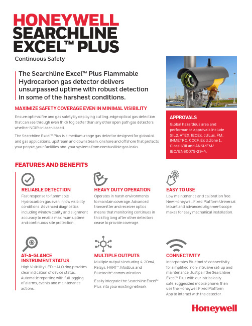
HONEYWELL SEARCHLINE EXCEL™ PLUS Continuous SafetyFEATURES AND BENEFITSRELIABLE DETECTIONFast response to flammable Hydrocarbon gas even in low visibility conditions. Advanced diagnostics including window clarity and alignment accuracy to enable maximum uptime and continuous site protection.HEAVY DUTY OPERATION Operates in harsh environmentsto maintain coverage. Advanced transmitter and receiver optics means that monitoring continues in thick fog long after other detectors cease to provide coverage.AT-A-GLANCE INSTRUMENT STATUSHigh Visibility LED HALO ring provides clear indication of device status. Automatic reporting with full logging of alarms, events and maintenance actions.EASY TO USELow maintenance and calibration free.New Honeywell Fixed Platform UniversalMount and advanced alignment scopemakes for easy mechanical installation. MULTIPLE OUTPUTSMultiple outputs including 4-20mA,Relays, HART®, Modbus andBluetooth® communicationEasily integrate the Searchline Excel™Plus into your existing network.APPROVALSGlobal hazardous area andperformance approvals includeSIL2, ATEX, IECEx, cULus, FM,INMETRO, CCCF, Ex d, Zone 1,ClassII/III and ANSI/FM/IEC/EN60079-29-4.The Searchline Excel™ Plus FlammableHydrocarbon gas detector deliversunsurpassed uptime with robust detectionin some of the harshest conditions.MAXIMIZE SAFETY COVERAGE EVEN IN MINIMAL VISIBILITYEnsure optimal fire and gas safety by deploying cutting-edge optical gas detectionthat can see through even thick fog better than any other open path gas detectorswhether NDIR or laser-based.The Searchline Excel™ Plus is a medium-range gas detector designed for global oiland gas applications, upstream and downstream, onshore and offshore that protectsyour people, your facilities and your systems from combustible gas leaks.CONNECTIVITYIncorporates Bluetooth® connectivityfor simplified, non-intrusive set-up andmaintenance. Just pair the SearchlineExcel™ Plus with our intrinsicallysafe, ruggedized mobile phone; thenuse the Honeywell Fixed PlatformApp to interact with the detector.Honeywell Searchline Excel TM Plus T echnical SpecificationsSee product manual for full specifications.Honeywell Searchline Excel TM Plus Accessories, Spares and System Part Numbers*******************。
Honeywell Vertex C有毒气体检测系统说明文件说明书
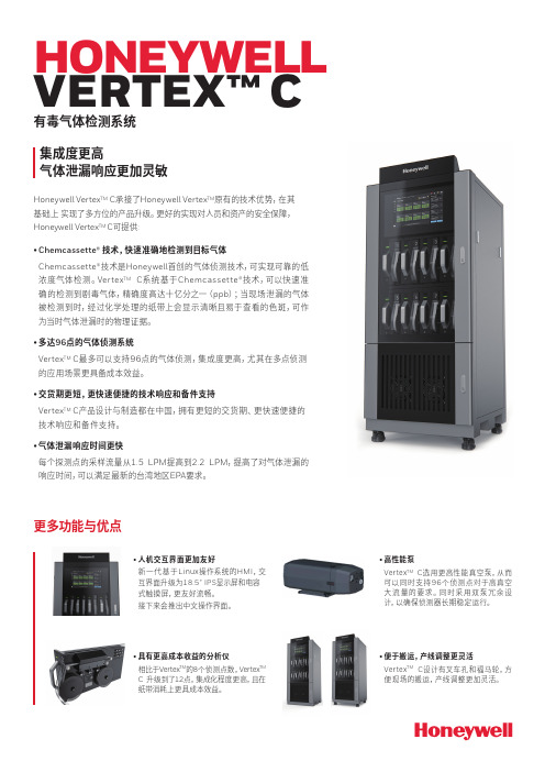
HONEYWELL VERTEX™ C 有毒气体检测系统集成度更高 气体泄漏响应更加灵敏Honeywell Vertex TM C 承接了Honeywell Vertex TM 原有的技术优势,在其基础上 实现了多方位的产品升级。
更好的实现对人员和资产的安全保障, Honeywell Vertex TM C 可提供: • Chemcassette® 技术,快速准确地检测到目标气体Chemcassette®技术是Honeywell 首创的气体侦测技术,可实现可靠的低浓度气体检测。
Vertex TM C 系统基于Chemcassette®技术,可以快速准确的检测到剧毒气体,精确度高达十亿分之一(ppb );当现场泄漏的气体被检测到时,经过化学处理的纸带上会显示清晰且易于查看的色斑,可作为当时气体泄漏时的物理证据。
• 多达96点的气体侦测系统Vertex TM C 最多可以支持96点的气体侦测,集成度更高,尤其在多点侦测的应用场景更具备成本效益。
• 交货期更短,更快速便捷的技术响应和备件支持Vertex TM C 产品设计与制造都在中国,拥有更短的交货期、更快速便捷的技术响应和备件支持。
• 气体泄漏响应时间更快每个探测点的采样流量从1.5 LPM 提高到2.2 LPM ,提高了对气体泄漏的响应时间,可以满足最新的台湾地区EPA 要求。
更多功能与优点•人机交互界面更加友好新一代基于Linux 操作系统的HMI ,交互界面升级为18.5” IPS 显示屏和电容式触摸屏,更友好流畅。
接下来会推出中文操作界面。
• 便于搬运,产线调整更灵活Vertex TM C 设计有叉车孔和福马轮,方便现场的搬运,产线调整更加灵活。
• 高性能泵Vertex TM C 选用更高性能真空泵,从而可以同时支持96个侦测点对于高真空大流量的要求。
同时采用双泵冗余设计,以确保侦测器长期稳定运行。
• 具有更高成本收益的分析仪相比于Vertex TM 的8个侦测点数,Vertex TMC 升级到了12点,集成化程度更高,且在纸带消耗上更具成本效益。
Honeywell iSeries 智能气体传感器诊断测试说明书
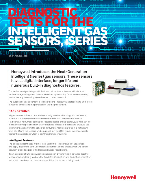
DIAGNOSTIC TESTS FOR THE INTELLIGENT GAS SENSORS, iSERIESTechnical NoteHoneywell introduces the Next-Generationintelligent (iseries) gas sensors. These sensorshave a digital interface, longer life andnumerous built-in diagnostics features.The iseries’ intelligent diagnostic features help enhance the overall instrumentperformance, making them smarter and safer by indicating faults and monitoringhealth, thereby decreasing downtime and cost of ownership.The purpose of this document is to describe the Predictive Calibration and End-of-lifefunctions, and outline the principles of the diagnostic tests.BACKGROUNDAll gas sensors drift over time and eventually need recalibrating, and the amountof drift is strongly dependent on the environment that the sensor is used in.Traditionally, instrument developers, fleet managers or end users would work out forthemselves by experience how often they need to recalibrate sensors, or would use recommendations from the sensor or instrument manufacturer as it is not knownwhat conditions the sensors are being used in. This often results in unnecessarilyfrequent recalibrations which is costly and time consuming.Intelligent FeaturesThe iseries platform uses internal tests to monitor the condition of the sensorand apply algorithms both to compensate for drift and to predict when the sensoraccuracy exceeds a predefined limit and needs recalibrating.It can also predict when it is wearing out and can give warning in advance that thesensor needs replacing. As both the Predictive Calibration and End-of-life indicationuse predictions based on the environment that the sensor is being used.Definition of Diagnostic TestsPredictive Calibration: The calibration process can be very tedious, costly and a time-consuming process. With this function, sensors can predict in advance whenits accuracy is becoming too poor to give a reliable reading. This function helps to identify exactly when a recalibration is required.The sensor can estimate the time to recalibration up to six months in advance. Recalibration intervals will be typically at least twice as long as for conventional sensors and will adapt depending on the environment – with sensors used in more benign environments needing less frequent calibrations than those in aggressive ones.The user can configure the accuracy limit of the sensor, and this will determine the interval at which the calibration is needed. In other words, the tighter the accuracy value, the more frequent calibration needed.The user can therefore trade off accuracy against recalibration interval. There is also a configurable built in fixed interval recalibration countdown timer for applications where legislation requires calibration at certain intervals.End-of-Life: The lifespan of a sensor depends mostly on the environmental conditions at which the sensor is exposed. With this function, the sensor can predict in advance when its sensitivity is falling too low to give a reliable and accurate reading. When the End-of-life function is triggered, the sensor automatically warns the instrument via a set of fault flags sent together with the gas reading. If the fault is detected the instrument can warn the user to stop using the sensor.How was the design of the sensor optimised?Honeywell engineers performed finite element analysis of the water management and electrolyte distribution within sensors and gained an extensive understandingof the optimum designs for retaining the electrolyte in the right place at the right concentration.Subsequently, safety operating area charts were developed based on a combination of fundamental physical theory, modelling and experimental verification to show how sensors will perform and withstand over the full temperature, humidity and time.To validate that the sensor will last in real-world applications, an environmental database was obtained. The database contains hundreds of locations around the world, with temperature and humidity data for 10 years with two hourly resolution. The knowledge of use cases for sensors was combined, for example time spent indoors and outdoors, charging to provide input data on the actual conditionssensors are exposed to in the real world. This information was fed into the models to predict how long sensors will last and how their performance will change in real world conditions, and to assist us in optimising the sensor design for maximum performance and life.The environmental performance data was generated by storing sensors in a rangeof environmental conditions over a two-year period. There were more than 8000 individual gas responses recorded for each gas typeDuring this period, the sensors were tested to generate different databases corresponding to the performance of the sensor at particular environments.The resulting predictive algorithm keeps track of the electrolyte concentration and environmental conditions over time and extrapolates this data with a linear regression in order to accurately predict when does the sensor need to be calibrated or when does the sensor is about to reach its lifespan.How does the predictive model for EoL and Predictive Calibration works?To estimate the EoL and Predictive Calibration, a 30-day time period is defined. During this period, the sensor will keep track of the environmental changes. The model works under the assumption that the sensor will be exposed to similar conditions.For instance, if the sensor has been in an extremely hot and dry environment, the predicted model will calculate the corresponding water loss as if the conditions remained the same; giving warning to the user in order to prevent further dry out. Figure 1 shows how the electrolyte concentration and predicted electrolyte concentration vary for a sensor in an extreme environment. The environment chosen corresponds to a challenging environment for the sensor to survive: during winter, outdoor temperatures can be -40°C or less, and in a heated unhumidified buildingor car, the relative humidity can be extremely low due to the very low water content of the cold outside air. Therefore, a sensor which spends part of the day indoors and part outdoors (a typical ‘field worker’ use case) not only gets very dry in winter but is also expected to function at very low temperatures.A perfect prediction (theoretical) would follow the dashed black line. In other words, the predicted days to recalibration would be exactly equal to the actual days to recalibration.The solid black line shows the true electrolyte concentration, which gets dry (high concentration) each winter but recovers to some extent each summer. The yellow line shows how the concentration has been predicted. The historical relative humidityis calculated from the average of another 30 days prior to that. As the prediction is made over a longer time, it becomes less accurate, mainly because the historical environmental conditions become less representative of the future conditions. How often does the sensor updates the EoL and Predictive Calibration?The diagnostic test runs automatically every 24 hours. However, the test is only performed when the sensor is in sleep mode, so it is highly recommended to change the sensor to sleep mode whenever it is not in use (otherwise the End of Life and Predictive Calibration estimations will not be updated/recalculated, leading to non-accurate results).The sensor needs to be in sleep mode at least two minutes per day, so it can update the EoL and Predictive Calibration values.What technique is used for the diagnostic tests?For this test, a smart indicative gadget is used as a diagnostic electrode. Thenan electrochemical technique called square wave voltammetry is applied to the electrode.The technique is a linear potential sweep voltammetry that uses a combined staircase potential and a square wave, which has the advantage of having better peak definition and location than conventional cyclic voltammetry or staircase voltammetry.The diagnostic test is performed to determine the electrolyte concentration of the sensor.Figure 2. Diagnostic TestingHow and when the End-of-Life and Predictive Calibration are flagged?The error and faults can be transmitted to the instrument every time it requests a gas reading from the sensor. For additional information about the gas reading format consult get data pack command (0x30) in the User’s Manual.Predictive Calibration alarm consists of two different parameters, and the • Thealarm will be triggered when either the countdown or the accuracy threshold are reached (whichever is triggered first):o The Predictive Calibration estimation will depend on the requested accuracy of the sensor. This parameter can be configured by the user: the tighter theaccuracy value, the more frequently the calibration.o Additionally, a countdown timer can be set by the user. This period can reflect the time required to calibrate the sensor, which may vary depending on thespecified standard or applications.• Likewise, the End-of-life is flagged when either the countdown or the future prediction algorithm conditions are met (whichever is triggered first):o The predicted End-of-Life algorithm is flagged when the sensor detects less than 50% of its initial sensitivity or when the electrolyte concentrationis above or below its limit. The sensitivity estimation is constantly updatedand its calculation is based on the measure at the minimum temperatures atwhich the sensor has been exposed to.o Along with this, there is a five-year countdown timer. The alarm is flagged after the sensor has reached its expected lifespan.How accurate are the End-of-life andPredictive Calibration functions?The predictive model for End-of-life and time to calibrationis highly accurate if the environmental conditions remainadequately constant.An analogy to this is the ETA (estimated time to arrival) in a car’s GPS system, which is based on previous average speed. If you travel at a constant speed, the ETA will count down linearly and be quite accurate over long distances. However, if you speed up or slow down the ETA could increase of decrease significantly throughout the journey. Similarly, if a sensor is kept in constant conditions, the future prediction based on historical conditions should predict a long way into the future quite accurately, and as a result the time to end of life or recalibration would decrease linearly over time. If the sensor is put into a more aggressive environment, then its predicted time to EOL/ recalibration will start to drop rapidly, whereas if a sensor that has been running in aggressive (e.g. dry) conditions is transferred to more benign conditions, the time to end of life or recalibration prediction may even increase over time.Other diagnostic tests:Just like the End-of-life and Predictive Calibration flags, the sensor can warn the instrument about other possible errors and failures that may appear on a sensor whenever a gas reading command is requested. These flags could also be used to indicate to the end user what type of maintenance is required, for example if the sensor warns that its electrolyte is getting too dry or wet the instrument could advise the user to store it in a suitable humidity environment to recover it.The following table shows the possible failures that the sensor may encounter along with their corresponding automatic detection methods:002717-2-EN | 2 | 08/21HoneywellAdvanced Sensing Technologies 830 East Arapaho Road Richardson, TX 75081FOR MORE INFORMATIONHoneywell Advanced Sensing Technol-ogies services its customers through a worldwide network of sales offices and distributors. For application assistance, current specifications, pricing, or the nearest Authorized Distributor, visit /ast or call:USA/Canada +302 613 4491Latin America +1 305 805 8188Europe +44 1344 238258Japan +81 (0) 3-6730-7152Singapore +65 6355 2828Greater China+86 4006396841WARRANTY/REMEDYHoneywell warrants goods of itsmanufacture as being free of defective materials and faulty workmanship during the applicable warranty period. Honeywell’s standard product warranty applies unless agreed to otherwise by Honeywell in writing; please refer to your order acknowledgment or consult your local sales office for specific warranty details. If warranted goods are returned to Honeywell during the period ofcoverage, Honeywell will repair or replace, at its option, without charge those items that Honeywell, in its sole discretion,finds defective. The foregoing is buyer’s sole remedy and is in lieu of all other warranties, expressed or implied, including those of merchantability and fitness for a particular purpose. In no event shall Honeywell be liable for consequential, special, or indirect damages.While Honeywell may provide application assistance personally, through ourliterature and the Honeywell web site, it is buyer’s sole responsibility to determine the suitability of the product in the application.Specifications may change without notice. The information we supply isbelieved to be accurate and reliable as of this writing. However, Honeywell assumes no responsibility for its use.。
有毒气体检测仪霍尼韦尔PHD

Honeywell PHD6智能型检测气体:LEL,O2,CO/H2S,PID,NO美国霍尼韦尔PHD6多气体检测仪是由霍尼韦尔提供的最先进的多气体检测仪;这是我们制造的配置最全的气体探测器,有5个探测器埠、6个气体通道和超过19个可选传感器,包括电化型、LEL、PID和红外式等各种型号;Honeywell制造的PHD6多气体检测仪可靠而精良,同时也保持了客户所期待的使用方便的特性;日常检测操作可完全通过模式Mode 键进行控制;状态显示器带有易于识别的图示,用户可快速查看包括时间、校准状态等的各项信息;植入式便捷导航功能表使高级用户能对探测器进行现场配置;PHD6多气体检测仪采用耐冲击聚碳酸酯框架结构,同时带有多模橡胶,结构坚固又便于操作;它采用可互换的碱性或锂离子充电电池组,电力可达24小时之久;其中包括一个气体手动采集工具包,并有气体采集电动泵备选;为了节约校准成本,并实现自动记录保存功能,Honeywell一起发布了IQ6 Express Dock及PHD6产品;IQ6 Dock能在一分钟内校准普通的PHD6多气体检测仪配置,既减少了工时,又降低了校准气体成本;如果你很重视保存以前的记录,IQ6 Dock能为您提供自动记录保存功能;PHD6多气体检测仪主要特征:•原装进口,品质保证,防护等级;IP65;•一体式电动泵,泵吸式和扩散式可随时切换•5个传感器埠和19个可选传感器•屏幕显示具备翻转功能;•可选PID传感器量程0-2000ppm,分辨率:•可选IR CO2传感器•可选电化传感器其中H2S传感器量程0-200ppm,分辨率;•可选LEL传感器,LEL传感器读数可显示为LEL百分比或CH4的体积百分比;•可选IR CH4传感器,IR CH4 传感器读数显示为1 –10000 PPM并能自动换算成%/V ol.•经久耐用•电池组: 采用可互换的碱性或锂离子充电电池组,电力可达24小时之久;锂离子电池组,可用电池组充电器进行反复充电;•双声报警使其脱颖而出•可视报警,报警方式:声、光、震动报警,特别具有防水报警,可防止仪器被液体侵蚀;•状态栏内图示易于辨识•IQ Dock兼容性•直观的功能表驱动式仪器配置•嵌入式IrDA埠便于下载•100英尺采样测试,超长距离采样一体泵,以适用于不同应用环境:最大软管长度为100英尺30米;•采样探针:采样探针手柄包括防潮装置和过滤装置,具有防水汽和气体颗粒污染物功能,用以去除可能损坏仪器的污染物;•1米处百次跌落测试,跌落测试报告:1米跌落测试>100次,具有测试报告;。
霍尼韦尔气体检测仪气体浓度单位

霍尼韦尔气体检测仪气体浓度单位霍尼韦尔气体检测仪是一种先进的装置,用于测量各种气体的浓度。
它采用了先进的传感器技术,可以准确地测量不同气体的浓度,并将结果显示在仪器的屏幕上。
在使用霍尼韦尔气体检测仪时,我们首先需要了解一些重要的概念和单位。
气体浓度是指气体分子在单位体积内的数量。
常见的气体浓度单位有毫克/立方米、百分比(%)和部分百万(ppm)。
毫克/立方米是指单位体积内气体分子的质量,通常用于测量一些有毒气体的浓度。
百分比是指气体在混合物中所占的百分比,常用于测量氧气和二氧化碳的浓度。
部分百万是指气体分子在百万分之一的单位体积内的数量,常用于测量一些微量气体的浓度,例如一氧化碳和甲烷。
霍尼韦尔气体检测仪可以根据用户的需要,将测量结果转换为不同的单位。
这意味着,无论我们需要测量哪种气体的浓度,都可以通过设置仪器来选择合适的单位。
除了测量气体浓度,霍尼韦尔气体检测仪还可以提供其他相关信息,如温度和湿度。
这些信息对于评估环境质量和安全性非常重要。
例如,在工业环境中,高温和湿度可能导致某些气体的浓度增加,从而增加了化学反应的风险。
通过同时测量温度和湿度,我们可以更好地了解环境的条件,并采取适当的措施来保护工作人员的安全。
在使用霍尼韦尔气体检测仪时,我们还应该注意一些注意事项。
首先,正确使用和校准仪器非常重要。
定期对仪器进行校准可以确保测量结果的准确性和可靠性。
其次,仪器应与气体接触的地方保持干净和干燥。
如果有灰尘、污垢或湿气存在,可能会导致仪器故障或不准确的测量结果。
最后,如果测量结果显示有害气体的浓度超过了安全标准,我们应该立即采取相应的措施,如通风、戴上呼吸器或者撤离危险区域。
总结而言,霍尼韦尔气体检测仪是一种非常有用的装置,它可以准确地测量各种气体的浓度。
我们只需设置合适的单位,并遵循正确的使用和校准步骤,就能获得可靠的测量结果。
此外,注意环境的温度和湿度,并且遵守相应的安全标准,可以确保我们的工作环境安全可靠。
有毒气体探测器标准
有毒气体探测器标准
1、可测量H2S、CO、SO
2、O2、O
3、C2H2、C2H3O 、C3H3N、 CL2、CLO2 、HCL、HCN、NO、NO2、H2、NH3、Br2、HBr、HCL、HCN 、HF 、CH3OH 、CH3SH 、COCL2、 PH3 、SIH4 、C4H6O2、 C2H3CL 、C2H5OH C2H5SH 等六十多种对有毒气体。
2、精巧的结构设计使仪器防护等级真正达到IP67,具有顶级的防水性能。
3、外壳新型化学材料及新型成型技术的应用,使仪器同时具备了极强的电磁屏蔽,及抗震抗摔抗酸碱腐蚀的特点。
4、独特的一键式操作,有效避免了使用人员误操作,以及普通一键式仪器维护人员设置繁琐的问题,使日常使用及参数设置更加简洁方便。
5、复位功能及OK模式的人性化设计,能最大限度的保障仪器长期正常工作。
6、鳄鱼夹、腰带夹以及独特的挂绳方式的同时供应,更利于仪器各种复杂环境的使用。
7、开机全自检,保证电路、传感器和电池正常工作;开机自动归零,保证每一次检测准确无误。
8、两级可调整的气体浓度报警,STEL及TWA报警。
9、1100 mAh大电池电量,电池10年长储存寿命。
霍尼韦尔气体侦测器原理
霍尼韦尔气体侦测器原理霍尼韦尔气体侦测器原理随着人们对空气质量和安全的要求越来越高,气体检测技术也逐渐得到广泛应用。
而霍尼韦尔作为国际知名的工业控制和自动化领域的领先企业,其独特的气体侦测器原理无疑成为了人们翘首期盼的话题。
1、气体侦测器基本原理气体侦测器的基本原理是使用物理、化学或电学的方式检测环境中是否存在特定气体。
在传感器中,感受到气体后,会产生一些可以被读取和测量的信号。
例如,电学类型的气体侦测器可通过探测器内的电极检测气体,从而产生电信号。
这些信号可以在屏幕上显示或通过传输到外部系统进行进一步处理。
2、热导型气体侦测器原理霍尼韦尔的气体侦测器中,热导型气体侦测器是一种很重要的类型。
它的工作原理基于导体的电阻随温度的变化而改变。
气体侦测器传感器由热物体和测量元件组成。
这个测量元件是一个微小的电阻器,电阻随温度的变化而变化。
当气体抵达传感器的热体部分时,气体吸收了一部分热,使热体温度降低。
由于传感器电阻与温度成反比例关系,因此当热体的温度下降时,电阻值将增加。
通过将该微小电阻器连接到一些简单的电路中,可以将电阻值转换为电信号,并提供给用户。
3、燃气探测器原理燃气探测器是另一种常见的霍尼韦尔气体检测器,其运行原理基于检测可燃气体的存在。
在燃气探测器中,探测器中的传感器测量气体的配比,并在该配比达到危险水平时发出警告或控制可燃气体释放。
其中,燃气探测器使用的传感器可以分为半导体传感器和热导传感器。
两种传感器皆需与电路连接,以将检测到的信息转化为电信号,并通过警报或其他控制机制提醒用户。
4、光学型气体探测器原理最后,光学型气体探测器是一种可检测特定气体存在的技术,其工作原理基于将光辐射反射在气体中并测量反射量。
通过光学检测器检测光反射量中的变化,可以确定气体是否存在。
此类传感器的准确性和稳定性较高,适用于严格监测条件下的空气质量控制。
5、小结总而言之,霍尼韦尔气体侦测器基于热导、光学、电学等原理实现气体的检测与预警,广泛应用于化工、能源、电子等工业领域,并满足不同用户的需求。
霍尼韦尔四合一气体检测仪说明书
霍尼韦尔四合一气体检测仪说明书霍尼韦尔四合一气体检测仪是一款先进、高效、精准的气体检测设备,广泛应用于石油化工、能源、环保、安防等领域。
本文将为您介绍该产品的详细性能和使用方法,让您能够更好地了解和使用这一设备。
一、产品特点:1.四合一检测:本仪器可同时检测氧气含量、可燃气体浓度、二氧化碳浓度和有毒气体浓度,可以满足多种检测需求,大大提高工作效率。
2.高灵敏度:本仪器配备高灵敏度的气体传感器,可以快速、准确地检测到各类有害气体,确保工作人员的安全。
3.多种报警方式:当气体浓度达到警戒值时,本仪器会自动报警,提醒工作人员及时采取应急措施。
同时,本仪器通过声音、震动、光线等多种方式报警,更加科学合理。
4.防爆设计:本仪器符合防爆设计标准,可以在爆炸性环境下安全使用,保障使用者的生命安全。
二、使用方法:1.开机:长按开机键3秒,显示屏亮起,进入检测状态。
开机时,在通风良好的场所让仪器自检,确保传感器正常工作。
2.检测:根据需要选择检测气体类型,将仪器靠近检测区域,等待检测结果。
3.报警:当气体浓度达到警戒值时,本仪器会自动报警,并在显示屏上显示警报类型和警报值。
此时,应立即采取应急措施,保证工作人员安全。
4.关闭:长按关闭键3秒,显示屏熄灭,仪器关闭。
三、注意事项:1.本仪器仅供专业人士使用,未经训练者不得使用。
2.在使用前应检查传感器是否正常工作,确保准确性。
3.本仪器不可用于检测空气含氧量,如需检测空气含氧量,请使用专业氧气检测仪。
4.本仪器在使用时应注意安全,避免破损和撞击。
5.在长期不使用时,应将本仪器放置在干燥、通风良好的环境中,并进行定期维护。
综上所述,霍尼韦尔四合一气体检测仪是一款先进、高效、精准的气体检测设备,可以广泛应用于工业、环保、安防等领域。
通过合理使用和维护,能够提高工作效率,保障工作人员的安全。
希望本文对您有所帮助!。
霍尼韦尔气体侦测器设置气体浓度单位

霍尼韦尔气体侦测器设置气体浓度单位
摘要:
I.引言
- 简要介绍霍尼韦尔气体侦测器
II.气体浓度单位设置
- 单位设置的重要性
- 常用气体浓度单位介绍
- 霍尼韦尔气体侦测器如何设置单位
III.设置单位的方法
- 具体操作步骤
- 注意事项
IV.总结
- 概括文章内容
- 强调单位设置的重要性
正文:
霍尼韦尔气体侦测器是一种广泛应用于工业生产、环境保护、公共安全等领域的气体检测设备。
在使用过程中,正确设置气体浓度单位是非常重要的,因为它直接关系到检测结果的准确性。
气体浓度单位包括体积浓度(PPM)、质量浓度(mg/m3)等。
不同的应用场景和目的,需要选择不同的单位。
例如,在环保领域,通常使用质量浓度单位来衡量污染物的排放量;而在工业生产中,体积浓度单位更为常用。
霍尼韦尔气体侦测器设置气体浓度单位的步骤如下:
1.打开侦测器,进入主界面。
2.在主界面上,找到“设置”选项,点击进入。
3.在设置菜单中,找到“单位”选项,点击进入。
4.在单位设置页面,选择需要设置的气体浓度单位,如体积浓度(PPM)或质量浓度(mg/m3)。
5.确认设置后,点击“保存”按钮,完成单位设置。
在设置单位时,需要注意以下事项:
1.根据实际应用场景和需求,选择正确的气体浓度单位。
2.确保侦测器的设置与实际使用环境相符,以获得准确的检测结果。
- 1、下载文档前请自行甄别文档内容的完整性,平台不提供额外的编辑、内容补充、找答案等附加服务。
- 2、"仅部分预览"的文档,不可在线预览部分如存在完整性等问题,可反馈申请退款(可完整预览的文档不适用该条件!)。
- 3、如文档侵犯您的权益,请联系客服反馈,我们会尽快为您处理(人工客服工作时间:9:00-18:30)。
Honeywell PHD6
智能型(检测气体:LEL,O2,CO/H2S,PID,NO)
美国霍尼韦尔PHD6多气体检测仪是由霍尼韦尔提供的最先进的多气体检测仪。
这是我们制造的配置最全的气体探测器,有5个探测器埠、6个气体通道和超过19个可选传感器,包括电化型、LEL、PID和红外式等各种型号。
Honeywell制造的PHD6多气体检测仪可靠而精良,同时也保持了客户所期待的使用方便的特性。
日常检测操作可完全通过模式( Mode ) 键进行控制。
状态显示器带有易于识别的图示,用户可快速查看包括时间、校准状态等的各项信息。
植入式便捷导航功能表使高级用户能对探测器进行现场配置。
PHD6多气体检测仪采用耐冲击聚碳酸酯框架结构,同时带有多模橡胶,结构坚固又便于操作。
它采用可互换的碱性或锂离子充电电池组,电力可达24
小时之久。
其中包括一个气体手动采集工具包,并有气体采集电动泵备选。
为了节约校准成本,并实现自动记录保存功能,Honeywell一起发布了IQ6 Express Dock及PHD6产品。
IQ6 Dock能在一分钟内校准普通的PHD6多气体检测仪配置,既减少了工时,又降低了校准气体成本。
如果你很重视保存以前的记录,IQ6 Dock能为您提供自动记录
保存功能。
PHD6多气体检测仪主要特征:
•原装进口,品质保证,防护等级;IP65。
•一体式电动泵,泵吸式和扩散式可随时切换
•5个传感器埠和19个可选传感器
•屏幕显示具备翻转功能;
•可选PID传感器(量程0-2000ppm,分辨率:0.1ppm)
•可选IR CO2传感器
•可选电化传感器(其中H2S传感器量程0-200ppm,分辨率;0.1ppm)
•可选LEL传感器,LEL传感器读数可显示为LEL百分比或CH4的体积百分比。
•可选IR CH4传感器,IR CH4 传感器读数显示为1 –10000 PPM并能自动换算成%/Vol.
•经久耐用
•电池组: 采用可互换的碱性或锂离子充电电池组,电力可达24小时之久。
锂离子电池组,可用电池组充电器进行反复充电。
•双声报警使其脱颖而出
•可视报警,报警方式:声、光、震动报警,特别具有防水报警,可防止仪器被液体侵蚀。
•状态栏内图示易于辨识
•IQ Dock兼容性
•直观的功能表驱动式仪器配置
•嵌入式IrDA埠便于下载
•100英尺采样测试,超长距离采样一体泵,以适用于不同应用环境:最大软管长度为100英尺(30米)。
•采样探针:采样探针手柄包括防潮装置和过滤装置,具有防水汽和气体颗粒污染物功能,用以去除可能损坏仪器的污染物。
1米处百次跌落测试,跌落测试报告:1米跌落测试>100次,具有测试报告。
