DC-DC转换器中应用MLCC电容应考虑的问题
MLC电容器常见缺陷的规避方法
MLC电容器常见缺陷的规避方法因其小尺寸、低等效串联电阻(ESR)、低成本、高可靠性和高纹波电流能力,多层陶瓷(MLC)电容器在电源电子产品中变得极为普遍。
一般而言,它们用在电解质电容器leiu 中,以增强系统性能。
相比使用电解电容器铝氧化绝缘材料时相对介电常数为10 的电解质,MLC 电容器拥有高相对介电常数材料(2000-3000)的优势。
这一差异很重要,因为电容直接与介电常数相关。
在电解质的正端,设置板间隔的氧化铝厚度小于陶瓷材料,从而带来更高的电容密度。
温度和DC 偏压变化时,陶瓷电容器介电常数不稳定,因此我们需要在设计过程中理解它的这种特性。
高介电常数陶瓷电容器被划分为2 类。
图1 显示了如何以3 位数描述方法来对其分类,诸如:Z5U、X5R 和X7R 等。
例如,Z5U 电容器额定温度值范围为+10 到+85℃,其变化范围为+22/~56%。
再稳定的电介质也存在一定的温度电容变化范围。
图1:2 类电介质使用3 位数进行分类。
注意观察其容差!当我们研究偏压电容依赖度时,情况变得更加糟糕。
图2 显示了一个22μF、6.3 伏、X5S 电容器的偏压依赖度。
我们常常会把它用作一个3.3 伏负载点(POL)稳压器的输出电容器。
3.3 伏时电容降低25%,导致输出纹波增加,从而对控制环路带宽产生巨大影响。
如果您曾经在5 伏输出时使用这种电容器,则在温度和偏压之间,电容降低达60%之多,并且由于2:1 环路带宽增加,可能产生一个不稳定的电源。
许多陶瓷电容器厂商都没有详细说明这一问题。
图2:注意电容所施加偏压变化而降低陶瓷电容器的第二个潜在缺陷是,它们具有相对较小的电容和低ESR。
在频域和时域中,这会带来一些问题。
如果它们被用作某个电源的输入滤波电容器,。
dcdc电路 输入电容 mlcc 替代 电解
dcdc电路输入电容 mlcc 替代电解下载温馨提示:该文档是我店铺精心编制而成,希望大家下载以后,能够帮助大家解决实际的问题。
dcdc电路输入电容mlcc 替代电解该文档下载后可定制随意修改,请根据实际需要进行相应的调整和使用,谢谢!并且,本店铺为大家提供各种各样类型的实用资料,如教育随笔、日记赏析、句子摘抄、古诗大全、经典美文、话题作文、工作总结、词语解析、文案摘录、其他资料等等,如想了解不同资料格式和写法,敬请关注!Download tips: This document is carefully compiled by the editor. I hope that after you download them, they can help you solve practical problems. The document dcdc电路输入电容 mlcc 替代电解 can be customized and modified after downloading, please adjust and use it according to actual needs, thank you!In addition, our shop provides you with various types of practical materials, suchas educational essays, diary appreciation, sentence excerpts, ancient poems, classic articles, topic composition, work summary, word parsing, copy excerpts, other materials and so on, want to know different data formats and writing methods, please pay attention!DCDC转换器是现代电子设备中常见的电源管理电路,其功能是将来自电源输入端的直流电压转换为输出端所需的不同直流电压。
中压高容MLCC的设计及性能

中压高容MLCC的设计及性能中压(Mid-Voltage)高容(High Capacitance)多层陶瓷电容(MLCC)是一种具有较高电容值和较高工作电压的多层陶瓷电容器。
它们通常用于需要在中压范围内实现高电容值的应用,例如电源模块、DC/DC 转换器和电机驱动器等。
1.材料选取:中压高容MLCC通常采用的材料是高介电常数的陶瓷材料,如镗制陶瓷材料(例如Ba0.5Sr0.5TiO3)或压制陶瓷材料(例如X7R)。
这些材料具有较高的介电常数和较低的介质损耗,能够实现高电容值和较低的电容器损耗。
2.结构设计:中压高容MLCC通常采用多层结构,通过多个陶瓷层和金属电极的叠层组合来实现较高的电容值。
通常采用的结构有外部电极型和内部电极型。
外部电极型是通过在陶瓷层的两侧分别涂覆金属电极来获取电容值,而内部电极型是通过将金属电极涂覆在多个陶瓷层之间的分隔层上来获取电容值。
3.尺寸和层数:中压高容MLCC的尺寸和层数也会影响其电容值和工作电压。
增加陶瓷层数可以增加电容值,但会增加电容器的尺寸。
同时,增加层数也会增加电容器的工作电压,因为每个陶瓷层可以承受一定的电压。
因此,设计中需要平衡电容值、尺寸和工作电压之间的关系。
4.陶瓷厚度:陶瓷层的厚度也会影响中压高容MLCC的性能。
较厚的陶瓷层可以增加电容值,但会增加电容器的尺寸。
因此,在设计中需要根据具体需求选择合适的陶瓷厚度。
1.电容值:中压高容MLCC的电容值是评估其性能的一个重要指标。
较高的电容值可以满足应用对高电容值的需求。
2.工作电压:中压高容MLCC的工作电压范围是另一个重要的性能指标。
它表示电容器可以承受的最高电压,工作电压需要根据应用需求来选择。
3.温度特性:中压高容MLCC的温度特性(通常使用TCR来评估)表示在不同温度下电容值的变化范围。
具有较低的温度特性的电容器可以在不同温度环境下保持稳定的电容值。
4.电容器损耗:电容器损耗是指电容器在工作过程中的能量损耗。
MLCC使用注意事项
MLCC微观结构特点(2)
2、高精密智能化印刷叠层技术 国际最先进Roll to Roll高精度成型印刷叠层方 式 智能化Mark点识别高精度定位叠层 重轧压丝网与与图形控制技术: 印刷重复度≦15 μ m ,厚度精度±7% 叠层精度±30 μ m ( 100~300层)
MLCC微观结构特点(3)
3、在等静压叠片时需要施加巨大的压力,使 多层陶瓷膜片紧密结合在一起,在等静压过程 会产生一定的扭曲、变形,这样就产生较大的 内应力。 4、内电极与陶瓷介质膜片热胀系数差异很大, 这样在烧结、冷却过程又增加内应力。 5、外电极与内电极的结合靠烧渗结合,这样 的结合力存在各向异性。 6、外电极与瓷体热胀系数差异较大,焊接时 的热应力会使外电极与瓷体结合处产生裂纹。
MLCC微观结构特点(4)
四、MLCC的机械性能特点:
1、机械强度:硬而脆,这是陶瓷材料的机械 强度特点。这也是陶瓷材料应用的局限性,人 们必须了解陶瓷的特点,并扬长避短。 2、热脆性:MLCC内部应力很复杂,所以耐 温度冲击的 能力很有限。因此焊接时必须预 热,要求预热温度与焊接温度的温差不超过 150℃
MLCC使用注意事项
-BBK
一、MLCC的微观结构(1)
MLCC (Multi-Layer Ceramic Chip Capacitor) 片式多层陶瓷电容器的英文缩写
MLCC的微观结构(2)
二、MLCC工艺过程简介
三、MLCC微观结构特点(1)
1、超薄的介质膜片 超薄陶瓷膜片流延技术相适应的抗还 原介质粉体材料 超细、高纯、液相合成(化学法) 介质厚度:7~ 15μ m,D50:0.7 μ m 介质厚度:2~ 6μ m,D50:0.3μ m 最新研究开发报道: D50:70 nm
MLCC 使用过程中的注意事项
MLCC使用过程中的注意事项: 5.1 电路设计: 5.1.1 工作温度: a. 电容器使用过程中避免超过其上限类别温度。
b. 表面温度以及自加热温度应该低于电容器的上限类别温度。
5.1.2 工作电压: 电容器的工作电压必须低于其额定电压。
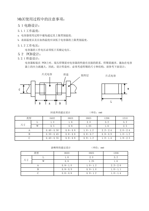
5.2 PCB设计: 5.2.1 焊盘设计: 电容器贴装在PCB上时,端头焊锡量对电容器的性能有直接的联系。
焊锡量越多,施加在电容器上的应力就越大。
因此,设计焊盘时,必须考虑焊锡的尺寸和结构,请参考下面设计: 回流焊的建议设计 (单位:mm) 类型 0402 0603 0805 1206 1210 L 1.0 1.6 2.0 3.2 3.2 尺寸 W 0.5 0.8 1.25 1.6 2.5 A 0.40~0.50 0.6~0.8 1.0~1.2 2.2~2.4 2.0~2.4 B 0.35~0.45 0.6~0.8 0.6~0.7 0.8~0.9 1.0~1.2 C 0.45~0.55 0.6~0.8 0.8~1.2 1.0~1.4 1.8~2.3 波峰焊的建议设计 (单位:mm) 类型 0603 0805 1206 L 1.6 2.0 3.2 尺寸 W 0.8 1.25 1.6 A 0.8~1.0 1.0~1.2 2.2~2.6 B 0.8~0.9 0.9~1.0 1.0~1.1 C 0.6~0.8 0.9~1.2 1.0~1.4 片式电容焊盘阻焊层片式电容弯曲扭曲5.2.2 电容器在PCB上的布局设计: 机械应力根据电容器在PCB上的位置不同而变化。
请参考下面的设计方案: 施加在电容器上的应力大小如下: A>B=C>D>E 注意:不要弯曲或扭曲PCB,否则电容器会发生断裂。
请参考下面的例子: a. 应该避免的情况: b. 建议的操作方式: 5.2.3 焊锡的应用以及焊接方式: a. 以下的焊接方式应该避免: b. 请参考以下的焊接方式: 5.3 自动化设计的注意事项: 如果安装头调整得过低,会产生过高的应力,导致电容器断裂。
mlcc电容击穿短路原因
mlcc电容击穿短路原因MLCC电容是一种多层陶瓷电容器,具有小体积、大容量、高稳定性等特点,在电子设备中被广泛应用。
然而,有时候我们会遇到MLCC电容击穿短路的情况,导致电子设备无法正常工作。
本文将探讨MLCC电容击穿短路的原因。
了解MLCC电容的结构对于理解击穿短路原因非常重要。
MLCC电容由多个层状电极和介质层组成,电极和介质层交替叠加形成多层结构。
电极通常由银或铜制成,而介质层则由陶瓷材料制成,如二氧化钛或氧化铝。
MLCC电容的击穿短路主要有以下几个原因:1. 动态电压异常:MLCC电容通常用于电子设备的滤波和解耦电路中,其工作电压范围广泛。
然而,当电容器承受超过其额定电压的过电压时,就会发生击穿现象。
过电压可能由于供电电源的故障、电路设计错误或其他因素引起。
因此,确保电容器所承受的电压不超过其额定值是避免击穿短路的重要措施。
2. 温度变化:温度的变化对MLCC电容的性能有很大影响。
当电容器在高温环境下工作时,陶瓷材料会膨胀,可能导致电容器内部应力的集中和破裂。
相反,当电容器在低温环境下工作时,陶瓷材料会收缩,可能导致电容器内部结构的破坏。
因此,在设计电子设备时,应考虑适当的温度范围以避免击穿短路。
3. 设计和制造缺陷:MLCC电容的设计和制造缺陷也可能导致击穿短路。
例如,电极与陶瓷材料之间的黏结可能不够牢固,导致电容器内部结构的不稳定性。
此外,电容器的表面涂层如果不均匀或存在缺陷,也可能导致击穿短路。
因此,在选择和使用MLCC电容时,应选择质量可靠的产品,并确保其符合相关的标准和规范。
4. 电压梯度:电容器的电压梯度是指电容器两个电极之间的电位差。
当电压梯度超过电容器的承受能力时,就会发生击穿短路。
电压梯度的大小与电容器的尺寸和结构有关。
较大的电容器通常能够承受更高的电压梯度,而较小的电容器则容易发生击穿短路。
因此,在设计电子设备时,应根据实际需求选择合适尺寸的电容器,并确保电压梯度在可接受范围内。
MLCC贴片电容选择及应用问题
MLCC贴片电容选择及应用问题MLCC(片状多层陶瓷电容)现在已经成为了电子电路最常用的元件之一.MLCC表面看来,非常简单,可是,很多情况下,设计工程师或生产、工艺人员对MLCC的认识却有不足的地方.以下谈谈MLCC选择及应用上的一些问题和注意事项。
MLCC虽然是比较简单的,但是,也是失效率相对较高的一种器件.失效率高,一方面是MLCC结构固有的可靠性问题,另外还有选型问题以及应用问题。
由于电容算是“简单”的器件,所以有的设计工程师由于不够重视,从而对MLCC的独有特性不了解.在理想化的情况下,电容选型时,主要考虑容量及耐压两个参数就够了.但是对于MLCC,仅仅考虑这两个参数是远远不够的。
使用MLCC,不能不了解MLCC的不同材质和这些材质对应的性能.MLCC的材质有很多种,每种材质都有自身的独特性能特点.不了解这些,所选用的电容就很有可能满足不了电路要求.举例来说,MLCC常见的有C0G(也称NP0)材质,X7R材质,Y5V材质.C0G的工作温度范围和温度系数最好,在-55°C至+125°C的工作温度范围内时温度系数为0 ±30ppm/°C.X7R次之,在-55°C至+125°C的工作温度范围内时容量变化为±15%.Y5V的工作温度仅为-30°C至+85°C,在这个工作温度范围内时其容量变化可达-22%至+82%.当然,C0G、X7R、Y5V的成本也是依次减低的.在选型时,如果对工作温度和温度系数要求很低,可以考虑用Y5V的,但是一般情况下要用X7R的,要求更高时必须选择COG的.一般情况下,MLCC厂家都设计成使X7R、Y5V材质的电容在常温附近的容量最大,但是随着温度上升或下降,其容量都会下降。
仅仅了解上面知识的还不够.由于C0G、X7R、Y5V的介质的介电常数是依次减少的,所以,同样的尺寸和耐压下,能够做出来的最大容量也是依次减少的.有的没经验的工程师,以为想要什么容量都有,选型时就会犯错误,选了不存在的规格.比如想用0603/C0G/25V/3300pF的电容,但是0603/C0G/25V的MLCC一般只做到1000pF.其实只要仔细看了厂家的选型手册,就不会犯这样的错误.另外,对于入门不久的设计工程师,对元件规格的数序(E12、E24等)没概念,会给出0.5uF之类的不存在的规格出来.即使是有经验的工程师,对于规格的压缩也没概念.比如说,在滤波电路上,原来有人用到了3.3uF的电容,他的电路也能用3.3uF的电容,但他有可能偏偏选了一个没人用过的4.7uF或2.2uF的电容规格.不看厂家选型手册选型的人,还会犯下面这种错误,比如选了一个0603/X7R/470pF/16V的电容,而事实上一般厂家0603/X7R/470pF的电容只生产50V及其以上的电压而不生产16V之类的电压了。
dcdc输入电容导致的问题

dcdc输入电容导致的问题
DCDC电路中,如果输入电容配置不当,可能会导致以下问题:
1. 输入电压波动:输入电容的主要作用是平滑输入电压,避免电压的突变和噪声对转换器的影响。
如果输入电容的容值不够大,在负载变化或电源波动时,输入电压的波动可能会增加。
这可能会导致输出电压的不稳定,甚至可能导致转换器无法正常工作。
2. 系统稳定性问题:输入电容容值不足可能导致输入电压的纹波增加,甚至可能影响到整个系统的稳定性。
3. 降低系统工作效率:输入电容容值不足可能会导致输入电压的纹波增加,这可能会降低系统的工作效率。
4. 输出电压纹波增加:输出电容的主要作用是输出电压的稳定和滤波。
如果输出电容的容值不足,可能会导致输出电压的纹波增加,使得负载的电压稳定性下降,这对于某些对电压稳定性要求较高的应用而言,可能会造成严重的问题。
因此,合理选择和配置输入电容是确保DC-DC转换器正常运行的重要环节。
MLCC常见问题及解决途径
MLCC常见问题及解决途径
陈增生
【期刊名称】《电子工艺技术》
【年(卷),期】2006(27)6
【摘要】近年来,片式陶瓷电容越来越多地应用于电子产品中,而不合理的设计、不恰当的操作方法,使产品在高低温循环、应力筛选等试验后,常常出现片式陶瓷电容失效现象.分析了电容失效的原因,并针对出现的问题,提出改进措施,以提高产品质量.【总页数】4页(P336-338,343)
【作者】陈增生
【作者单位】中国电子科技集团公司第三十六研究所,浙江,嘉兴,314033
【正文语种】中文
【中图分类】TM5
【相关文献】
1.初中英语词汇教学常见问题及解决途径探析 [J], 韦爱素
2.合编教材策划中的常见问题及解决途径 [J], 孙静
3."新工科"背景下,地方应用型高校的大学生创新能力培养模式常见问题及解决途径[J], 周石磊;罗晓;岳琳;吕鹏翼
4.农村土地承包经营管理的常见问题及解决途径 [J], 姚荔明
5.企业人力资源规划的常见问题及解决途径分析 [J], 吴维芳
因版权原因,仅展示原文概要,查看原文内容请购买。
mlcc电容降压
mlcc电容降压MLCC电容是一种多层陶瓷电容器,常用于电路中的降压功能。
在这篇文章中,我将介绍MLCC电容的工作原理、优势以及在降压电路中的应用。
让我们来了解MLCC电容的工作原理。
MLCC电容由多个金属电极和陶瓷层组成。
这些金属电极分别与电源和负载连接,通过陶瓷层的绝缘性质,实现电荷的储存和释放。
当电流通过MLCC电容时,电容器会储存电荷并产生电场,这样就形成了一个电压降。
当负载需要电流时,电容器会释放储存的电荷,从而降低电压。
MLCC电容在降压电路中具有许多优势。
首先,MLCC电容的体积小,重量轻,可以方便地集成到各种电子设备中。
其次,MLCC电容的响应速度快,能够快速地储存和释放电荷,适用于高频电路。
此外,MLCC电容的可靠性高,具有较长的使用寿命和稳定的性能。
最重要的是,MLCC电容的成本相对较低,适合大规模生产和应用。
MLCC电容在降压电路中有着广泛的应用。
在直流-直流(DC-DC)降压电路中,MLCC电容常用于滤波器和稳压器中。
滤波器通过将高频噪声滤除,提供纯净的直流电压。
稳压器则通过控制电容器的充放电过程,稳定输出电压。
此外,在交流-直流(AC-DC)转换器中,MLCC电容也可以用于降压和滤波功能。
除了常规的降压电路,MLCC电容还可以应用于一些特殊的领域。
例如,在LED驱动电路中,MLCC电容可以用于电源滤波和稳压,确保LED的正常工作。
在电动汽车和太阳能系统中,MLCC电容可以用于能量转换和储存,提高能源利用率。
在使用MLCC电容进行降压时,我们需要注意一些问题。
首先,选择合适的电容值和额定电压是非常重要的。
电容值过小会导致电压降低不足,而电容值过大则会增加电路的体积和成本。
其次,要合理设计电路板布局,减小电容器与其他元件的干扰。
此外,温度也会影响MLCC电容的性能,因此需要考虑散热和温度补偿措施。
MLCC电容在降压电路中扮演着重要的角色。
它具有体积小、响应速度快、可靠性高和低成本等优势,适用于各种电子设备和应用领域。
DCDC转换器如何选择电感与电容
DCDC转换器如何选择电感与电容DC-DC转换器是一种将直流电压转换为不同电压级别的器件。
在选择电感和电容时,需要考虑转换器的工作频率、功率要求、效率、体积、成本等因素。
接下来将从这些方面详细介绍如何选择电感和电容。
1.工作频率:工作频率是选择电感和电容的关键因素之一、转换器的工作频率通常为几十千赫兹到几兆赫兹,不同频率的转换器对电感和电容的要求也不同。
一般来说,工作频率较高的转换器需要使用低电感值和小电容值的元件,而工作频率较低的转换器则需要使用高电感值和大电容值的元件。
2.功率要求:转换器的功率要求是选择电感和电容的另一个关键因素。
功率要求高的转换器通常需要使用高电流承受能力的电感和电容,以保证转换器的稳定性和可靠性。
此外,功率要求高的转换器还需要考虑元件的能量损耗、温升等因素,以确保转换器的高效率运行。
3.效率:效率是转换器的重要指标之一,也是选择电感和电容的重要考虑因素。
较高的效率意味着转换器的能量损耗较小,因此在选择电感和电容时应考虑其损耗等效系列电阻和损耗等效并联电阻等参数。
通常选择较低电感值和小电容值的元件可以提高转换器的效率。
4.体积:转换器的体积是另一个需要考虑的因素。
较小体积的转换器往往需要较小的电感和电容。
因此,在选择电感和电容时应考虑其尺寸和重量,以满足转换器体积小、重量轻的要求。
5.成本:成本是选择电感和电容的重要考虑因素之一、较大电感值和较大电容值的元件通常成本较高,而较小电感值和较小电容值的元件成本相对较低。
在选择电感和电容时,应根据转换器的成本预算,选择性价比高的元件。
综上所述,选择适合的电感和电容需要综合考虑工作频率、功率要求、效率、体积和成本等因素。
需要注意的是,不同转换器的特性和要求有所差异,因此在选择电感和电容时应根据具体的应用场景进行综合考虑,并多进行实验验证。
MLCC电容器使用注意事项

板分割工艺
应使用夹具或某种设备(圆刀分切机、刨刀式分切机 等)进行印刷电路板裁切,以避免在电路板上出现机 械应力。 对单侧贴装手工分板注意着力点如下:
组装注意
以下动作都可能产生板弯曲从面导致电容 裂纹:
•应力移动 •贴装其他元件 •将带引线的元件插在电路板上 •安装/拆下插座 •拧紧螺钉
PCB板焊盘设计
选择适当安装位置和方向,使电路板弯折时施加在该电容器上的应力 最小。
PCB板焊盘设计
选择适当安装位置和方向,使电路板弯折时施加在该电容 器上的应力最小。
PCB板焊盘设计
选择适当安装位置和方向,使电路板弯折时施加在该电
容器上的应力最小。
焊接工艺
元件突然受热,会降低其机械强度。原因是较大的温度变化会导致
内部变形。为防止造成机械损坏,应对元件和PCB板进行预热。
焊接工艺
1206及以上大规格不推荐波峰焊.
ΔT≤1修
最佳焊料量
焊料量过大,则在弯曲或其他应力条件下存在很大的断裂机率。
烙铁头形状 如何使用烙铁
≤ ø3mm直径烙铁头。过 程中需要防止烙铁直接 接触元件,尤其对陶瓷 体的接触。 应使用ø0.5mm或更细的
PCB板焊盘设计
(1)所用焊料量的大小会影响芯片抗机械应力的 能力,会导致电容器破碎或开裂。设计基板时, 须慎重考虑焊盘的大小和配置,这些对组成基 板的焊料的量有着决定的作用。 (2)如果不止一个元件被连续焊接在同一基板或 焊盘上时,焊盘的设计应可以使每个元件的焊 接点被阻焊区隔离开。
PCB板焊盘设计
PCB板弯曲引起的电容裂纹,在焊接后手工 分板过程和测试、装配过程中产生的。工业标准 集团和生产商现有的弯曲标准规范是以前为引线 型陶瓷电容做的,但PCB弯曲度或挠度经常超出 片式电容器的承受范围。
逆变器内高压mlcc的作用
逆变器内高压mlcc的作用逆变器内高压MLCC的作用随着可再生能源的快速发展和应用,逆变器作为将直流能源转换为交流能源的关键设备之一,广泛应用于太阳能发电、风能发电等领域。
而在逆变器中,高压多层陶瓷电容器(MLCC)扮演着重要的角色。
本文将从多个方面介绍高压MLCC在逆变器内的作用。
高压MLCC在逆变器中起到了储能的作用。
逆变器在运行过程中,需要将输入的直流电能转换为交流电能,而这个转换过程是间断的。
在直流电能输入过程中,高压MLCC会吸收并储存一部分电能,然后在转换过程中释放出来,以平衡电能的间断性,确保交流电能的稳定输出。
通过高压MLCC的储能作用,逆变器可以提供更加稳定的电能输出,提高电能的利用效率。
高压MLCC在逆变器中还可以起到电压滤波的作用。
逆变器在运行过程中,输入电流会产生一定的涟漪电压,这会对电能输出的稳定性产生影响。
通过在逆变器内部设置高压MLCC,可以有效地减小电压涟漪,降低电能输出的波动,提高逆变器的工作稳定性和输出质量。
高压MLCC还可以用于电流滤波。
在逆变器中,由于电能的转换过程不可避免地会产生一定的电流涟漪,这会影响到逆变器的工作效率和输出质量。
通过在逆变器内部设置高压MLCC,可以将电流涟漪降低到较低的水平,保证逆变器的电流输出稳定,提高逆变器的工作效率。
高压MLCC还具有抑制电磁干扰的能力。
由于逆变器内部存在高频电压和电流,会产生一定的电磁干扰。
而高压MLCC具有良好的高频特性和电磁屏蔽性能,能够有效地抑制电磁干扰的产生和传播,保证逆变器的正常工作和输出的电能质量。
高压MLCC还具有体积小、重量轻等优点,适合在逆变器中的紧凑空间内使用。
由于逆变器通常需要在较为狭小的空间内进行安装,高压MLCC的小体积和轻重量使得其在逆变器中的布局更加灵活方便,有助于提高逆变器的整体性能和可靠性。
总结起来,高压MLCC在逆变器内起着储能、电压滤波、电流滤波和抑制电磁干扰等多重作用。
MLCC常见问题及解决途径
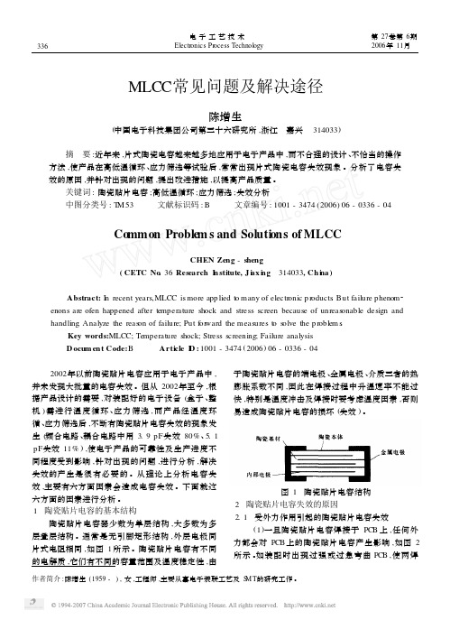
陶瓷贴片电容器少数为单层结构 ,大多数为多 层叠层结构 。通常是无引脚矩形结构 ,外层电极同 片式电阻相同 ,如图 1 所示 。陶瓷贴片电容有不同 的电解质 ,它们有不同的容量范围及温度稳定性 ,由
于陶瓷贴片电容的端电极 、金属电极 、介质三者的热 膨胀系数不同 ,因此在焊接过程中升温速率不能过 快 ,特别是温度冲击及焊接时要考虑温度因素 ,否则 易造成陶瓷贴片电容的损坏 (失效 ) 。
[ 3 ] 白秀茹. 典型的密封式电子设备结构热设计研究 [ J ]. 电子机械工程 , 2002, 18 (4) : 36 - 38.
[ 4 ] Sussan Crum. A ttaching heat sinks to components [ J ]. EP&P, 1997 (1) : 42 - 46.
[ 5 ] Crowe G. Thermal analysis and op tim ization of a small,
high density de power system by finite element analysis ( FEA ). Proc [ J ]. IEEE Int Energy, 1996 ( 10 ) : 718 -
图 3 电容破损
图 4 电容断裂 (3)由于陶瓷贴片电容端头 (本体与电极 )结合 力不良的质量问题 ,经焊接 、温冲 、调试等外力作用 等过程 , 容易引起金属电极脱落 ,即本体与电极脱 离如图 5所示 。 2. 2 焊接操作不当引起的失效 2. 2. 1 电烙铁手工焊接操作不当或返工 电烙铁焊接所带给陶瓷贴片电容的热冲击是很 普遍的 。焊接时会产生热冲击 ,如果操作者将烙铁 尖端直接接触电容电极 ,就会出现热冲击引起陶瓷 贴片电容器本体的微裂 ,一段时间后陶瓷贴片电容 就会失效 。原则上陶瓷贴片电容一般应由 SM T专
MLCC常见故障分析
MLCC常见故障分析MLCC指多层[或叠层]陶瓷电容器, 由于生产成本较其它电容器低,ESR[等效串联电阻]和ESL[等效串联电感]极低,因此,被广泛使用在各类高频电路.它的产量占电容器总产量的70%以上. 进些年MLCC的技术进步非常快, 其体积容量比已经接近钽电容器的水平.由于其独特的无极性结构非常适合滤波使用,因此,在微电子电路上的应用范围不断扩大.大有代替部分体积容量比较低的片式钽电容器的势头.尽管其在高频特性上优点突出,但其弱点也经常导致使用出现问题; 例如在-55-+125度的极限温度内其容量变化率较大,不能满足使用温度变化幅度过大,滤波精度要求高的电路. 另外,由于叠层厚度的增加导致产品的机体变的更'脆',在焊接上板冷却后非常容易出现由于电路板热应力导致的叠层裂纹,出现裂纹的产品在常温时漏电流变大,在电路板温度升高时漏电流反而降低,因此,查找原因非常困难.当通过的电流很大时,一样可以突然出现发热导致的电击穿现象,有时候甚至还会出现烧板现象.导致MLCC焊接后叠层出现裂纹的根本原因,是高温焊接后冷却过程中线路板和MLCC机体不同的膨胀率, 因为MLCC的基材是氧化物组成的陶瓷材料,因此,其非常脆,也就是说在叠层较薄时非常容易在极微小的热应力下断裂. 其容易断裂的比列随容量的增加而增加,因为,容量高的MLCC,其叠层数量越多,而且每层厚度也更薄,目前最薄的叠层厚度已经达到1微米左右.使用此类产品,必须非常注意产品与焊接温度曲线及焊接材料和电路板材料间的选择问题, 稍微有一点的热应力就有可能导致部分MLCC的部分叠层出现断裂.出于对MLCC较大容量产品的对热应力导致的失效比列增加的担心,按照美军电子元件使用规定,军用MLCC的叠层厚度不能小于10微米,也就是说一定容量的MLCC产品,体积过小的产品不容许在军用电子电路中使用. 因为其非常容易出现在温度变化过大时突然断裂而导致失效率增加.实际上,上述原因导致的失效比比皆是, 特别是在民用电子产品上,由于过度追求小体积导致的此类问题已经导致电路可靠性大幅度降低, 出现的问题非常多.为了解决此问题,美国一家公司开发了一种端子涂敷了导电高分子聚合物的MLCC, 此产品主要解决的问题就是MLCC产品耐热应力差的缺点.可悲的是我国生产的此类产品在质量等级上与国外公司的差距仍然在扩大,而在向用户提供产品时,多数生产厂家都对此缺点避而不谈, 从而使许多用户对因此问题导致的失效率问题越来越多.。
电容使用注意事项与失效解决方案
电容使用注意事项与失效解决方案一、电容使用注意事项1. 选择适当的电容类型和参数在选择电容之前,需要根据电路的需求来确定适当的电容类型和参数。
常见的电容类型包括陶瓷电容、铝电解电容和钽电解电容等。
不同的电容类型具有不同的特性和应用范围,因此需要根据具体的电路设计来选择合适的电容。
2. 注意电容的额定电压和电流在使用电容时,需要注意其额定电压和电流。
超过电容的额定电压或电流可能导致电容失效或损坏。
因此,需要确保电容的工作电压和电流不超过其额定值。
3. 避免电容短路电容在使用过程中可能出现短路现象,这会导致电路故障或电容损坏。
为了避免电容短路,可以采取以下措施:- 在电容两端加入合适的保险丝或保护电路,以防止电容短路时造成过大的电流流过电容。
- 在安装电容时,确保电容的引线之间没有短路或接触到其他导体。
4. 注意电容的极性某些类型的电容具有极性,如铝电解电容和钽电解电容。
在使用这些电容时,需要注意其正负极性,否则可能会导致电容损坏或电路故障。
在安装电容时,应确保正极与正极相连,负极与负极相连。
5. 避免过热和过电压过热和过电压是电容失效的常见原因之一。
为了避免过热和过电压,可以采取以下措施:- 在电容两端加入合适的散热器,以提高电容的散热能力。
- 使用合适的电压稳压器或过压保护装置,以防止电容过电压。
二、电容失效解决方案1. 电容短路当电容发生短路时,可能会导致电路故障或电容损坏。
解决电容短路问题的常见方法包括:- 检查电容引线之间是否存在短路或接触到其他导体,如果存在短路,需要修复或更换电容。
- 检查电容两端的保险丝或保护电路是否正常工作,如果保险丝熔断或保护电路触发,需要修复或更换保险丝或保护电路。
2. 电容损坏电容可能因为过热、过电压或其他原因而损坏。
解决电容损坏问题的方法包括:- 检查电容是否超过了其额定电压或电流,如果超过,需要更换电容并确保新电容符合电路需求。
- 检查电容是否过热,如果过热,可以在电容两端加入散热器或提高散热条件。
2. mlcc常见技术问题及解决方案 (4)2

2. Ⅱ类陶瓷介质老化特性 Ⅱ类陶瓷介质(包括X7R、X5R及Y5V特性类)的 电容器使用的是铁电体材料。当温度低于居里温 度时,介质的立方晶体结构转为四方相,其对称 性降低,晶体点阵中的离子会连续移动到势能较 小的位置,引起电容量按对数规律随时间不断地 减小,这一现象称为Ⅱ类陶瓷介质材料的老化现 象,一般引用老化常数来表示,X7R/X5R材质的 老化常数约-1%~-2%, Y5V材质的老化常数约3%~-4%。
㈡电容本身不良原因 a.料孔太大或太窄; b.纸带偏薄,模具打孔磨损太大,纸带孔偏小 卡料; c.纸带受潮,膨胀的纸带会缩小料孔的空间; d.下盖带过粘,下盖带烙铁头温度过高,致使 下盖带粘附力过强(产品编带后放置过久); e.上盖带中途断掉,致使中途抛料; f.产品外观有缺陷.
上锡不良
• MLCC自身方面: 端头氧化等。 • 客户端生产不良: 预热不足;焊锡温度过低或温度不均 传送速度过快、过慢 热风速率太大 焊盘PAD氧化或基板受潮 锡膏选型兼容不好、锡膏失效、锡膏印刷厚度太薄 焊盘设计过大、过小与产品不匹配 产品贴装移位
客户端上板后测试电容容量不良 (端头脱落、剥落) PCB组装调试、整机组装及运输过程中轻微 撞击及人为操作不当等产生较强的机械应 力冲击而造成的。
脱落、剥落实例
抛料(行业标准≤0.3%,具体依设备定)
㈠ 客户端不良原因
a.Feeder选用不当; b.Feeder上料盘装载不当规范; c.吸嘴(nozzle)清洗不清洁, 真空压力不足; d.吸嘴吸取中心未校正,吸料时发生偏移; e.开机时未机械归零; f.PCB的表面不平整; g.元件数据库相应参数长、宽和厚设置不当; h.相机镜面脏污; i.作业员操作不当(未按上料流程作业).
MLCC老化特性如下图所示:
陶瓷电容器(MLCC)设计注意事项
5.2.2 过度清洗时
1) 过度清洗可能会破坏MLCC的端电极的连接,导致电容器电性能不良。 2) 当用超声波清洗时,输入过高的超声波能量会对贴片电容器的本体与端
电极间的连接产生影响。为了避免这些,请注意以下事项:
功率: 20W/L max 频率: 40kHz max. 清洗时间: 5 分钟 max.
手工焊接方法
溫度 (℃) 功率 (W) 烙鐵直徑(mm) 300 max. 20 max. Φ3.0 max.
2)电烙铁与MLCC本体直接接触,极易导致MLCC开裂。勿使烙铁与端电极接触。
正确的手工烙铁焊接方法:通过烙铁加热焊锡丝,让焊锡丝熔融后将MLCC端 电极与焊盘焊接在一起。
注意事项(5)─清洗
[注意] 由于电介质损耗,当在电容器两端施加交流电压时,电容器产会产生自发热,特
别是在高频接近电容器的自谐振频率时会生极高的热量,以致损坏电容器自身贴 装制品。
所设计的电路应保证电容器表面温度包括自发热所引起的温度须低于电容器所 允许的最大工作温度。
1.2 工作电压
1) 端子间的工作电压必须低于额定电压。当在电容器上同时施加交流与直 流电压时其最大峰值电压必须低于额定电压;同样地当交流或脉冲尖峰 信号峰值须低于额定电压。
2) 即使在满足低于额定电压的条件下,若在电容上反复施加高频交流电压或 脉冲电压,电容器的信赖性也会因此被削减。
3) 减小输入电压的额定值将会大大降低失效率,因为失效率与电压的3次方成 比例, 即额定电压为UR的制品在工作电压为UW时其失效率按(UW/UR)3的比 例降低。
注意事项(2)---PCB Lay-Out设计
PCB设计总原则
总的原则是在设计PCB Layout时,要考虑到在贴片、焊接、分 板、测试、装配、运输等各制程中MLCC尽可能受到较小的应力作用, 确保MLCC在使用过程中不会损坏。
mlcc 电容漏电流
mlcc 电容漏电流
电容漏电流是指电容器在直流(DC)工作条件下,由于电介
质的不完全绝缘或其它因素引起的电荷的渗透、扩散等现象引起的电流。
电容器是被用来储存电荷的设备,根据电容的定义,当电压施加在电容器两端时,电荷会在电容器的两个电极之间积聚。
在直流工作条件下,由于电介质的不完全绝缘,部分电荷会从一个电极穿越电介质进入另一个电极,形成漏电流。
这是由于电介质的导电性造成的,它可以是由于电介质的导电污染、缺陷、潮湿等原因引起的。
电容漏电流的大小与电压、电容器内部结构、电介质材料等因素相关。
当电容器的电压较高时,漏电流较大。
同时,电介质材料的质量和纯度也会影响电容器的漏电流。
为了减小电容漏电流,可以采取以下措施:
1.选择高品质的电容器,以避免电介质的质量问题。
2.降低工作电压,使用合适的电压等级的电容器。
3.在设计电路时,考虑合理的保护措施,如使用适当的绝缘材
料或采取补偿电路等。
4.定期检测电容器的漏电流,及时更换老化或漏电的电容器。
需要注意的是,漏电流并非一定是不可避免的,通过合理的设计和选用合适的电容器,可以将漏电流控制在可接受范围内。
【经验分享】MLCC相关的问题(一)
【经验分享】MLCC百问百答(一)MLCC即是多层陶瓷电容片式,是电子信息产品不可或缺的基本组件之一。
我国MLCC 的生产起步在80年代初,行业早期主要是在外资企业的带动下发展起来的,近年来国内企业在技术上实现突破,行业国产化成效显著,并推动了MLCC产量迅速增长。
目前,MLCC的应用领域已从手机、电脑、电视机等消费电子领域,逐步拓展到新能源发电、新能源汽车、节能灯具、轨道交通、直流输变电、三网融合、高清电视、机顶盒、手机电视等多个行业。
对于这个悄悄活跃在人们生活中的元件你又知道多少呢,易容网编辑整理了关于MLCC行业诸多问题及答案如下:1.什么是MLCC?答:MLCC是英文Multi-layerceramiccapacitors的简称,中文意思是多层陶瓷电容.MMuliple多LLayers层次CCeramic陶瓷CCapacitor电容器2.MLCC由哪些材料组成?答:MLCC主要由绝缘体材料和电极材料组成,绝缘体材料主要使用陶瓷,其包括TiO2(二氧化钛)、BaTiO3(钛酸钡)、CaZrO3(锆酸钙)等,电极材料一般选用AgPdalloy(银钯合金).3.MLCC是结构如何构成的?答:基本构造是将陶瓷和内部电极交相重叠,具体参见下图1.图1:MLCC结构图4.MLCC有哪些参数?答:MLCC的常用的参数有容值,容差,材质,尺寸(厚度),额定电压,耐电压,DF 值,IR值。
5.MLCC有哪些用途或类型?答:根据MLCC的制作工艺和参数,在各个电子领域都有相对应的用途和分类,一般有普通型陶瓷贴片电容,Q值高或高频型陶瓷贴片电容,逆转型陶瓷贴片电容,排容型陶瓷贴片电容,汽车级陶瓷贴片电容,微波型陶瓷贴片电容,低等效电感类的陶瓷贴片电容,降低噪声功能的陶瓷贴片电容,防止短路设计的陶瓷贴片电容,三端子类的陶瓷贴片电容,安规类的陶瓷贴片电容等等.6.根据MLCC的结构可以计算它的容值吗?如何计算?答:可以计算,计算公式C=K×[(S×n)/t]这里,C=电容量,K=介电常数,n=介电层层数,S=电极面积,t=介电层厚度7.MLCC是如何生产制造的?参见下图2.图2:MLCC制造工序8.MLCC和其它电容比较有哪些好处?答:MLCC是相交重叠两端电镀的结构,原材料丰富,结构简单,价格低廉,而且电容量范围较宽(一般有几个PF到上百μF),损耗较小,电容量温度系数可根据要求在很大范围内调整,和其它的电容器相比具有体积小、容量大、耐热性好、适合批量生产、价格低等优点,迎合了当今“更轻、更薄、更节能“的设计理念.9.全世界有多少生产MLCC的生产商?都在哪里?答:全世界大约有20多家MLCC生产商,经常使用的生产商如下:日本:京瓷(KYOCERA)、村田(MUTATA)、丸和(Maruwa)、TDK、太阳诱电(TAIYO).韩国:三星(SAMSUNG).美国:基美(KEMET)、AVX.台湾:达方(DARFON)、禾伸堂(HEC)、国巨(YAGEO)、华新科(WALSIN).大陆:宇阳(EYANG)、风华高科(FENGHUA).10.目前全世界尺寸最小的MLCC有多小?是那家公司制造的?答:目前全世界尺寸最小为008004(公制为0201),其L*W=0.25mm*0.125mm,由日本村田公司制造.更多问题及解答请时刻关注易容网资讯内容更新……。
- 1、下载文档前请自行甄别文档内容的完整性,平台不提供额外的编辑、内容补充、找答案等附加服务。
- 2、"仅部分预览"的文档,不可在线预览部分如存在完整性等问题,可反馈申请退款(可完整预览的文档不适用该条件!)。
- 3、如文档侵犯您的权益,请联系客服反馈,我们会尽快为您处理(人工客服工作时间:9:00-18:30)。
1Use of MLCC CapacitorsApplication NoteOctober 2005Multi-layer ceramic chip (MLCC) capacitors are used quite often in dc-dc converter input and output filters instead of tantalum or aluminum electrolytics. MLCC’s have low ESR, low ESL, and low cost. They also have no major reliability problems associated with them. All these properties make them suitable for powermanagement applications. There are still, however, some issues to consider when using these capacitors in dc-dc converter circuits. Some ceramic capacitors can lose a lot of their value under certain conditions. This lost capacitance can degrade the transient response of a dc-dc converter, or it can even make the control loop of the converter unstable.First of all, we only recommend using C0G, X7R, or X5R dielectrics. Since C0G capacitors are not available except for lower values, X7R and X5R become the only suitable choice for most cases. We stronglyrecommend against using Y5V or any similar dielectrics in the input and output of a dc-dc converter. These capacitors will lose up to 90% of their value in many typical operating conditions.The capacitance per unit volume of the X7R/X5R dielectrics has increased quite a bit in the past few years. However, you should be careful about using the components with the highest capacitance densities. These capacitors lose a lot of their value at the higher frequencies where most dc-dc converter circuits operate. They lose even more capacitance when dc bias is applied to them.Table 1 compares some typical X7R/X5R capacitor values in various case sizes made by a major manufacturer. We first measured the capacitor value with no dc bias at frequencies >100kHz using a network analyzer, and found the higher the capacitance density, the lower will be the value at high frequencies. Next, we examined the manufacturer’s curves regarding the drop in capacitance at dc as a function applied bias voltage, and found again that the higher density capacitor values drop faster with dc bias.NominalVoltage Measured Value % Capacitance DropCap Value Case Size Thickness Rating at 0V DC Bias (Typical)freg>100kHz 3V DC Bias 5V DCBias10uF 0603 0.8mm 6.3V 5.2uF 45% 67%0805 1.25mm 10V 7uF 20% 40%1206 1.6mm 10V 10uF 5% 12%1210 2mm 25V 10uF 2% 5%22uF 0805 1.25mm 6.3V 12uF 33% 55%1206 1.6mm 6.3V 19uF 15% 33%1210 2.5mm 16V 19uF 1% 8%47uF 1206 1.6mm 6.3V 35uF 33% 60%1210 2.5mm 6.3V 43uF 12% 28%1812 2.5mm 6.3V 47uF 10% 20%Table 1: Comparison of various ceramic cap values and case sizesRev 1.2 – October 2005 2Use of MLCC CapacitorsFor example, neglecting the initial part-to-part tolerance and temperature effects, a 10uF/10V/1206 capacitor used in the input or output filter of a high-frequency dc-dc converter will actually be 9.5uF at 3V or 8.8uF at 5V. However, an 0805 capacitor with the same value and ratings can be as low as 5-6uF at 3V and 4-5uF at 5V, assuming that the frequency and bias voltage effects are cumulative. This is quite a difference in capacitance from the nominally designed value.Based on the results shown in Table 1, we believe the optimum footprint for a 10uF capacitor is 1206, and for a 47uF capacitor is 1210. The 1812 footprint works slightly better than the 1210 for the 47uF, but we don’t feel the small improvement is worth the added space and cost. For a 22uF capacitor the optimum footprint could be either 1206 or 1210 depending on the application.Sometimes the designer may just want to get the maximum capacitance in a limited available footprint. If, for example, there is only room for a 1206 capacitor, the 47uF part will still have the most capacitance even if it loses a larger percentage of its value than the 22uF or the 10uF parts. In other applications, the product cost may also impact the chosen footprint. For example, if a 1210, 22uF capacitor is significantly more expensive than a 1206, then the 1206 component may be preferred even with the larger capacitance drop.The third column in Table 1 shows the thickness (height) of each component. Manufacturers sometimes make the same capacitance and footprint in various heights. This is sometimes done to accommodate different voltage ratings. If the application allows, choose the thickest component available for a given capacitance and footprint. The taller capacitors have thicker dielectric layers that will not degrade as much with bias voltage or with frequency. All the components shown in Table 1 are the tallest available capacitors at the time of this writing.It should be noted that the conclusions drawn in this design note are based on our measurements andobservations on a small sample of parts as of this writing. In fact, the effect of frequency on capacitance cannot even be found in most manufacturers datasheets including the one used in this study. As technology improves in the future, the recommended optimum footprint for a specific value capacitor may become smaller.Nevertheless, the issues raised here will still be applicable, and dc-dc converter design engineers should always pay attention to them.。
