ICEM surf 中文教程
ICEM中文版Tutorial_Manual

由yzmylh提供,版权所有……Ansys icemcfd 5.1 tutorial部分内容粗略翻译及理解,水平有限,如有问题或建议请联系liqingliang@,不胜感激。
感谢redhong等众多网友提供的资料和帮助,本人正在学习cfx,希望大家多多交流。
ANSYS ICEMCFD 5.1使用手册1. ANSYS ICEMCFD图形用户界面ANSYS ICEMCFD网格编辑器的标准化图形用户界面,提供了一个完善的划分和编辑数值计算网格的环境。
另外,自从ANSYS ICEM CFD 将相应的CAD模型(同样可以生成和编辑)与网格划分链接起来以后,网格编辑器允许用户在修改CAD模型后快速再生成新的网格。
对于为一个模型生成的网格可以被再次链接到一个新的CAD模型上,节约了重新划分网格的时间。
网格编辑器界面包括三个窗口:ANSYS ICEM CFD 主窗口模型的树状目录ANSYS ICEM CFD 信息窗口1.1:ANSYS ICEM CFD 主窗口除了图形显示区,在它的上部设置了一排按钮提供操作菜单,这些菜单包括:几何,网格,块,网格编辑,输出和post processing工具。
窗口的右上角有一串功能菜单,它们与以上这些菜单的选择无关。
文件:文件菜单提供许多与文件管理相关的功能,如:打开文件、保存文件、合并和输入几何模型、存档工程,这些功能方便了管理ANSYS ICEM CFD工程。
在这个菜单里有用的功能包括:新建工程、打开工程、保存工程、另存为、关闭工程、改变工作地址、几何菜单、网格属性、参数、结果、输入几何模型、输入网、输出几何模型和退出。
带有特殊标记的功能按钮包含有子菜单,可以通过点击看到。
编辑:菜单包括回退、前进、命令行、网格转换小面结构、小面结构转化为网格、结构化模型面。
视图:菜单包括合适窗口、放大、俯视、仰视、左视、右视、前视、后视、等角视、视图控制、保存视图、背景设置、镜像与复制、注释、加标记、清除标记、网格截面剖视。
ICEM Surf -Shape Diagnoses中英帮助文档

11.8.1
Shape Diagnoses – Reflection 形状分析—反射
Course of reflection and highlight lines 反射和高光线课程
Reflection lines are created with this diagnosis allowing an exact evaluation of surfaces. 用这种诊断方式创建的放射线能精确的评估曲面。
折弯不能接受。因为它们表示诊断线不连续。
The diagnostic line is continuous at the patch matching. However, not the curvature continuity at the patch edge point is decisive, but the continuous course of the curve across several patches. 已匹配片的诊断线应该是连续的。但并不由匹配边上的点是否曲率曲面上的点。由 反射角得到放射线和曲面法向。 b)在光源方向上,光线将以同样 的角度被反射。光源位于从曲面点 到指定距离的直线段上。 2.计算反射线上更多的反射点 不 a)光源会被三角化 懂 b)曲面上更多的点也会被从光源按 eye 指定的距离计算。这些点构成反射 point 线。
11
Z Y X
反射分析原理 11.8.1.3 Principle of the reflection diagnosis
light source in X direction
light source in Z direction
杆状光源沿径向发出光线。每一 条光线都通过指定或计算反射在 曲面上。 反射线是条从曲面点到观察点的 一条直线。观察点由Display –
ICEM中文帮助文档

量。 • 允许将三维扫描数据直接生成的高质量模型通过中间格式或直接接口输
出其他系统中。
1.7. ICEM 可视化显示(ICEM Visualisation)和 ICEM 反求工程的 主要命令
统一模型:通过 ICEM 逆向工程模块可实时的将曲面模型投影到参考数据上,实 时调节曲面数据与 CAD 数据的偏差,在保证曲面连续(G1 连续)的同时可定义 固定几何体(Fixed geometry)
辅助曲面数据:应用 ICEM 逆向工程模块的曲面造型工具可将诸如边界、半径定 长或变长的圆角,剖面图和回转体添加到曲面模型中,可通过定义偏置距离实体 化原始曲面。还可 以反射到地面上和/或环境中的窗户上。反射能随着模型的移动而动态的改变。
透明度:曲面可以定义为透明的或者是半透明的。这样就可以通过挡风玻璃观察 汽车内部的人,比如说。也可以用来显示复杂的装配视图。
模型导航器:ICEM Vis 可以使用户从内部和外部用不同视角动态的观察模型。 观察设备包括:动态摄像, 角度摄像, 检查模式, 视图区域合聚焦设定。
1.3. ICEM Visualisation(ICEM Vis)
ICEM Vis 是一个标准的软件包,可以构建逼真的三维 CAD 模型,这些模 型可由 ICEM Surf 软件(汽车业界首选的曲面造型软件)及其 他商业工程软件或是两 者集成的软件所产生。它可以非常快捷、容易的生 成高质量的具有逼真效果的 静态 CAD 曲面模型和具有可视化效果的动态模型 ,也作为现场演示以及模型评
1.2. ICEM Surf
ICEM Surf 包括了创建、建模、分析和几何图形的实时显示等功能。特 别是在 曲面的可视化设计中得到了很好的应用,包括汽车、摩托车、商务车、农业和建 筑用车,以及体育用品和耐用消费品等诸多领域。
ICEM Surf 4.12 软件分享及详细图文安装教程
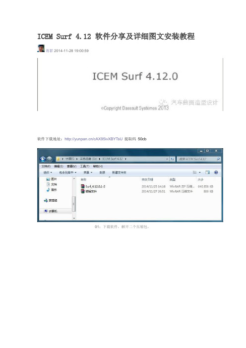
ICEM Surf 4.12 软件分享及详细图文安装教程蒋群2014-11-28 19:00:59软件下载地址:/cAX95ivXBYTsU提取码50cb01:下载软件,解开二个压缩包。
02:运行Setup。
03:选择Next下一步。
04:设置好需要安装的目录,选择Next下一步。
05:点击Next 下一步06:点击Yes 下一步继续。
07:点击OK 完成安装。
08:接下来完成破解部分的工作。
09:破解文件目录。
10:把lic win_b64二个文件,放到软件安装目录(win_b64替换原来的win_b64)。
11:打开安装目录下的license,进行修改lic设置12.完成license修改lic设置,然后保存帮助文件的使用方法。
14:如果help帮助文件读取失败,把win系统自带IE设置成默认浏览器,就能够读取了,或者找到软件安装目录下的:icemsurf-4.12.0\manual\english\index 也能打开help。
出错问题。
如:不能正常启动或读取License失败,请留言吧,我会在线提供协助!分享到微信推荐4人喜欢喜欢回应推荐喜欢2015-03-09 21:10:40 单车盼盼可以问下icem surf的版本问题嘛?哪个版本是最新的呀,怎么看到4.8版本的还是以前的?2015-03-12 19:34:02 蒋群 (使无力变成有力)可以问下icem surf的版本问题嘛?哪个版本是最新的呀,怎么看到4.8版本的还是以前的?单车盼盼ICEM surf目前最新版本是4.12.2015-04-24 22:54:34 熊子11步中替换的号码前面用红线盖住了。
还是就是改成495?2015-05-02 18:29:59 蒋群 (使无力变成有力)11步中替换的号码前面用红线盖住了。
还是就是改成495?熊子你自己的Mac 地址2015-06-04 18:19:19 autoAnti不管是多少次都是提示The desired vendor daemon is down 求助啊2015-08-01 13:26:49 蒋群 (使无力变成有力)不管是多少次都是提示The desired vendor daemon is down 求助啊autoAnti重装系统,换成win7 64位的。
ICEM CFD 中文教程

Example on using commercial software“ICEM CFD 5.1”Flow around a circular cylinderYTwo Dimensional problemsFlow around a circular cylinderProblem DescriptionAir flows across a cylinder with the uniform velocity in the wind tunnel. The length of the wind tunnel (fluid domain) has 25m long and 10 m height. The diameter of cylinder is 1m .Assumption and Boundary Conditions: 1. 2 dimensional problems 2. Steady state condition 3. The uniform flow velocity 4. No Heat transfer5. Neglect the gravitational force6. Constant air densityPre-processing stageIn this stage, we implement the “ICEM CFD” to perform the pre-processing work. The basic steps as follow:1. Establish geometry model2. Block the parts3. Generation the O grid4. Mesh the model and check quality of mesh5. Extrude the mesh6. R eset the BC’s (boundary conditions)7. Output toCreating Geometry1. Open ICEM CFDDouble Click the “ICEM CFD” Icon , afterwards, you can see the interface of the ICEM CFD.InletOutlet5DCylinderWall (SideB) Fluid domain5D20DWall (SideA)Open File>New Project…:2. Creating Geometry:A.PointsClick button “C reate Point ” and then click button “Explicit Coordinates ”Set the points in Cartesian coordinate system(X, Y, Z) with( X=0, Y=0, Z=0 ) respectively.Click “Apply” button and see the screen: a point is createdA tree widget can be seen at left of the screen (A) and (B)A BThe same method creates other points:X=-5; Y=5, -5X=20; Y=5, -5B.Draw line (curve)First of all see the tree widget, open Model>Geometry>Points by right buttonSelect Show Point Names and you can see the name ofeach point like the figure showed.Now you can create curvesClick button “Create/Modify Curve”Click button “Create Curve”Note: the left corner of the black screen: Select locationswith left button, middle=done, right=cancelSelect points by using left button of the mouse.Change the name of the Part with “INLET”:A BSelect and with left button (A),And draw a line with middle button “done”(B) and the INLET part is created in the tree widget.The same steps draw the curves named “OUTLET, SIDEA, SIDEB” with the 7and 8, and , POINTS.05 and respectively.We will see the line and the tree widgetDraw the cylinderClick button“Circle or arc from Center point and 2 points on plane ”.Set the Part with name “CYLINDER”Click button and select points “POINTS.00,POINTS.01, POINTS.03” with left button respectively(A).A BDraw the cylinder by middle button (B).See tree widget:Close Points name Use button to fit the window.Set the body and material.Click button “Create Body”Choose button “Mater ial Point”and select“Selected surfaces” in the “By Topology” menu.Change the name of the part with “FLUID”; open theShow Point Name of the tree widget and use selectand .The same way change the part name with “CYLINDER”and select and .Close Show Point Name and open the tree widget:Open the bodies and you can seeAt last, open the File>Geometry>Save Geometry As…Give it the name with “cylinder_2d”. Click “save”.Now we begin to block the model.Click button “Create Block”See the first one , choose the part with “FLUID”,from the pull down menu select “FLUID”And set the Initialize Blocks type with “2D Planar”Click “Apply” button.A BWe will see that the colors of figure are changed. From (A) to (B)See the tree widget: Model>BlockingThen create some assistant points with button “CreatePoint”{Y=0X=-0.45,-0.4,-0.35,-0.3,-0.25,-0.2,-0.15,-0.1,-0.5, 0.5,0.1, }{X=0}Now begin to block the regionClick button “Split Block”Then select button “Split Block”See the split method, select “Prescribed point”Use the put down menu to select the Prescribed point,Use the button firstly select the Edge “INLET” andsecondly select the Point “POINTS.03”.We will see the block line in the vertical direction of theINLET.Zoom the fiure.The same way we draw other block lines.From the to POINTS.04”See the tree widgetSelect the “Blocking” and select “Index Control”Model>Blocking: Index Control (using right button of the mouse) We can see at the right corner of the screenBy using button and we set I min=2 and see the figure The same way we set I max =3 , J min=2 , J max=3And the screen shown thatThe same way block again from to POINTS.44”:(A)(B)(C)A B CAfter block.See the tree widget: Model>Parts>VORFN :using the right button select “Add to Part”. Click button “Blocking Material”, Add Blocks to PartUsing select blocking regions and we can seeZoom the block regions (A).Select the blocks in the cylinder or attached the cylinder (B)(C).Using the middle button to set it OK , and you can see blow (D).Click button “Associate”ABD CSelect the associate edge to curve “Associate Edge toCurve”buttonUsing the choose the edge and curveChoosing edge:Select curves:Middle button:CBASet O gridClick button “Split Block”Click “Ogird Block”buttonSelect theSee the tree widget: Open Model>Parts>VORFNOpen the VORFN (A)AUsing button to selectin or attached the cylinder (B)(C)(D).B CD EUsing middle button to click “Apply”(E)Close “VORFN” from the tree widget (F)F GClick the “Reset”(G)Mesh the edgesClick button “Set Curve Mesh Size”Using button to select Curve(s):Choose Method with “Element count”Set the Number with 100 and click Apply.See the tree: close the Model>Geometry>points, and theModel>Blocking>edgesUsing right button to select Model>Geometry>Curves:Curve Node Spacing (by using right button)The same way set the “INLET” and “OUTLET” withnumber 100, the “SIDEA” and “SIDEB” with number 250.Click button “Pre-Mesh Params”Choose Blocking >Pre-Mesh ParamsClick button “Update Sizes” and keep default,Then click ApplySee tree open Model>Blocking>Pre_Mesh: Project faces(by using right button)And we will see a menuClick Yes.Now we will see the mesh of the model.Zoom it see the local partClose Geomery>Points and curves, and Blocking>Edges.Then open File>Mesh>Load from BlockingOpen File>Mesh>Save Mesh As…: and set the name with “cylinder_2d”Open File>Blocking>Save Blocking As…: Save block with the name “cylinder_2d”Check the quality of the meshClick button “Display Mesh Quality”Click ApplyWe can see no negatives mesh.Extrude meshClick button “Extrude Mesh”Use to select Elements:Method 1Click button “Select items in a part” and a menu appears:Click “All” and “Accept”Method 2A BPut the left button and drag it to select all the regions (A)(C). Click middle button to accept (B)Give the New volume part name “FLUID2D”, new side part name “SIDE”, new top par name “TOP”And set the Spacing type>spacing with ”, then ApplyCSo the mesh change a height in the Z direction (D)DBox ZoomE FClick button “Shaded Full Display”(E)(F) Check the quality of the extrude meshSee the tree widget:Close top “TOP” (B) Close “FLUID” (C)A BSet the new boundary conditionsSee the tree widget:Model>Parts: Create Part (by using the right button)Click “Create Part by Selection ” button From the pull down menu of the Part: select the “CYLINDER ” Using and left button drag the regionUsing middle button accepts it, so a new CYLINDER boundary condition has been set (C).CBACThe same way set the INLET, OUTLET, SIDEA and SIDEB boundary conditions. INLETThe Whole Boundary Conditions See the tree widget: CA BA Open Model>Parts>FLUID(B)B Open Model>Parts>TOP(C)CSix kinds of patterns Click File>Mesh>Save Mesh As… And save the new mesh with name “cylinder_2d_extrude”.Output the mesh file to CFXClick button “Select solver ” and choose “CFX-5” Click “Okay ”C B FE D AClick button “Write input”Keep default and click “Done”Then the Domain selection appearsKeep the Selected domains with “cylinder_2d_extrude.uns” and click “Done”.Now we will see the created files in working directions:From these files, we must note that only the file named “cfx5” can be inputted in to .1 The mesh is finished.Other examples:。
ICEMsurf一般控制功能

ICEM® Surf 4.3.0Reference ManualTechnologiesICEM Surf的一般控制功能2.1启动和关闭ICEM SurfWindows平台可以启动ICEM Surf 在Windows NT中由Start – Programs. Recovery?ICEM Surf 将重新启动你又可以直接的进行你的工作,恢复你的数据。
Cancel icemsurf?出现下面的信息:Recovery wanted in the next ICEM Surf session? (y/n)• yICEM Surf 将在下一次启动时提供现在退出时的数据状态。
• n原始数据的更改将丢失。
在恢复数据后,在继续工作前,你应该保存你恢复的状态。
2功能窗口2.1设置功能参数和选项:在功能窗口设置功能参数和选项,将使用下面的元素:按钮标记框一个标记框有多个标记框组成,这些按钮被独立的开关切换。
Radio Box /单选按钮一个单选按钮由很多关联的单选按钮组成。
只能有一只按钮能进行开关切换。
Popup Menu/弹出菜单Text Field/文字区域在文字区域你可以输入文字和数字并且能够用键盘和鼠标编辑它们.有两种类型的文字区域可用:o动态区域: 输入不被确认将被执行。
o非动态区域: 输入必须用Enter, Ctrl + M或者Ctrl + J确认。
下面的标记在文字区域可能用到:滑块手柄工具条可以用鼠标操纵滑块以设置一个值。
滑块由一个水平的(或竖直的)工具条和一个用于移动工具条的手柄组成。
如果相应的值在文字区域用数字设置,则手柄将自动位于该数字相应的位置。
滚轮滚轮可以用鼠标旋转以设置相应的数字。
选择列表标题标签如窗口顶部的标签,其文字不能更改。
移动帮助当鼠标指针移动到按钮上面,那么移动帮助可用。
具有一个简单功能说明的窗口出现。
2.2 窗口脚本的标准功能在功能窗口的下面的区域,此标准功能在所有的窗口都具有相同的意思。
ICEM入门教程(基础部分整理)
ICEMCFD /AI*Environment 特性?
几何 创建/修复/简化 强大的网格工具 – – – 从CAD模型、带网格的CAD模型、网格模型生成四面体网格 面网格, patch 依赖, patch 不依赖, 射, 结构/非结构 六面体网格雕塑, 非结构, 结构, 四边形网格拉伸 映
•
网格编辑
– – – – –
2013-8-17
CFD FEA FSI (CFD + FEA) CFX Workbench
5
不同应用
• FEA 版本
– 前后处理包括加载, 约束和属性标签栏, 与 FEA 求解器例如ANSYS, ABAQUS, LS-DYNA 和NASTRAN协同工作.
• CFD 版本
– 前后处理但不包括加载, 约束和属性标签栏,包含棱柱网格生成工具. 为100多种 CFD求解器输出网格 .
•
• • •
ቤተ መጻሕፍቲ ባይዱ
六面体网格雕塑 非结构/结构
边界条件 输出支持100多种求解器 后处理
•
… 其它…
2013-8-17 8
广泛的 CAD 支持
• 三维实体
– – – – – IGES ACIS Parasolid DWG/DXF GEMS
SolidWorks
Pro/Engineer
• 小平面(三角面)数据
.prj
• 主要文件类型:
– Tetin 文件(.tin) – 几何及网 格参数 – Domain 文件(.uns) – 网格文件 – Attribute 文件(.fbc) – 网格参数 和边界 – Parameter 文件(.par) – 参数
2013-8-17 28
.tin
ICEM-曲面的创建-02

ICEM_surf——创建曲面ERICLEI 的修改会实时显现在屏幕上。
如下图:OFFSET对话框:OFFSET对话框是用来设置融合曲面的边界线在原始曲面上的位置,默认选项为ISO-CURVE,该对话框中的其它设置很少用到,建议保持默认设置,对其它选项稍作了解即可对话框中各项含义如下:__EDGE 1 表示融合曲面的第一条边界线,B(BEGIN的缩写)表示边界线的起点,E (END)表示边界线的终点——这些选项是用来定义融合边界线在原始曲面上的位置的具体选项,意义如下(以下的说明是以第一条边界线(EDGE 1)为例,对于第二条边界线(EDGE 2)同样适用):——系统默认设置,选择此项用户可进入上述的SHAPE对话框对融合曲面的边界线位置进行定义——用户可直接输入融合曲面边界线偏离原始曲面边界线的具体数值——进入该项后,系统会要求用用户选择一个中心点,然后再输入融合曲面边界线在原始曲面边界线上的偏移量,系统会以所选择的中心点为基准来作出融合曲面,此项与LINEAR选项的不同之处就在多了一个计算基准的中心点——该项与VARIABLE选项不同之处在于它允许用户选择多个原始曲面边界线上的点,并分别输入在这些点的位置处融合曲面边界线相对于原始曲面边界线的偏移量,系统会依据这些数据来作出融合曲面FACE建面该功能用来剪切曲面,用户可选择一条或多条曲面边界线或曲线或量测线或诊断线来剪切曲面,这些用来修剪曲面的几何体不一定要求在曲面上,在进行剪切时也可按照用户所选择的工作平面来进行投影剪切。
下图是选择一条曲面上的曲线来修剪曲面,若只是用一条曲线来修剪曲面则该曲线必须能够将曲面分成二部分才能进行FACE用户选择用来剪切曲面的几何体也可以多于一个,且这些几何体不要求首尾相连但最起码应能与曲面的边界或是其自身构成一个封闭的区域将曲面分为二个或二个以上的部分,系统会视用户所选择的希望保留下的区域作出相应的剪切。
如下图所示:下图是选择四条曲线来剪切曲面的情形:下面是另外四条曲线对曲面进行剪切后的效果,请注意与上图不同之处在于有二条曲线的端点在曲面的边界上,所以在选择曲面保留区域时比前者有更多的选择。
ICEM_CFD 基础入门教程 操作界面 中文
• 许多分支允许通过双击获 取选项
11
模型树: Parts
• Parts 分枝包含加载的文件中所有的parts 列表 • 对于活动的parts 所有的网格单元和几何类型将显示在图
形窗口
– 除非 “Subsets” (子集)激活 (见下一节)
• Create Part(创建): 右击弹出选项:
– 简便的限制数据显示 – 更易于使用 • 消隐特定的实体
在选择模式, 按 F9 切换到动态 取消 模式; 再按 F9 切换回来
多边形
选择全部
选择可见部分
7
热键
选择实体(点、线、面、体、网格)时, 可以使用热键:
– a – 选择全部 – v – 所有可见 – m –切换框选择和多变形选择区域模式,在如下两种模式间切换:
工作流程 16
新工程
1 2
17
读入/导入几何
• 如果几何是其它 CAD或neutral 格式 选择 “File > Import Geometry > . . . “ 选择相应的 CAD File (ICEM 自动创建*.tin 文件)
• 如果几何已转为ICEM 格式 (*.tin), choose “File > Geometry > Open Geometry . . . “ 选择 .tin 文 件
Mesh Size Controls
生成网格
网格尺寸控制
Shell, Tet, Prism, Hexa (old gui) 面、四面体、棱柱体、六面体(老界面)
Create Connectors Create Elements
创建连接
创建单元
20
ICEM教程

ICEM教程第一篇:ICEM教程根据自己的体会写的操作说明。
一.非结构化网格的一般步骤:1,导入几何体(Ug中定义family,输出tin文件)2,检查体:Repair Geometry(有时需要补面),给边界面取名。
检查体时,如果出现黄线,就说明几何体有问题,红色、蓝色线为正常的。
3,生成body,(非结构化网格必须依据body生成,流通区域建立body,如果要算热态的,固体区域也要生成body;有几个封闭区域生成几个body,且其名称必须不同。
)4, 设置全局网格(global mesh setup< global mesh size>,< set up periodicity>)。
在Global Mesh Setup 设置参数。
为了加密孔上的网格,要用Curvature/Proximity Based Refinement。
Refinement为近似圆时的多边形的边数。
5,设置周期边界网格,周期面上的网格必须一致,所以必须在设置周期面之后才能计算网格(compute mesh)。
使用mesh sizes for parts命令。
周期面必须要定义base(回转轴的基点),Angle (扇形面的角度),在这里旋转轴与ug中的模型有关,如果ug中不是以三个基准轴的话,就要自己找点(用Geometry的做点法来定)。
6,计算网格Compute Mesh。
7,display mesh quality,如果网格质量不行,可以在局部区域使用creat mesh density命令加密网格。
8,smooth Elements Globaly,Smoothing iterations一般选择25次,Up to quality一般为0.4 9,choose slovr 10.边界条件可以选择在fluent中设置(设置边界条件Boundary Conditions),直接输入网格二.一些操作技巧:要查看内部网格,可以点中mesh再单击右键,选择cut planes; creat mesh density,如果设置的尺寸不对,需要修改,点中Geometry下拉菜单中的density再单击右键,选择modify density。
ICEMsurf中文教程
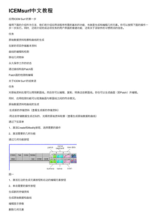
ICEMsurf中⽂教程应⽤ICEM Surf 的第⼀步借⽤下⾯的介绍作为引⾔,我们将介绍应⽤该程序所需的基本的功能,也就是⽣成和编辑⼏何元素。
你可以按照下⾯的操作⼀步⼀步执⾏。
同时,还将介绍完成这项任务的⽤户界⾯的普通功能,还有关于该软件的习惯⽤法的信息。
任务原始数据资料轮廓和曲线的⽣成在新的项⽬存储基本资料曲线的编辑和检测移动⼏何物体永久保存⼯作的状态通过曲线构造Patch⾯Patch⾯的检测和编辑关于ICEM Surf 的结束语任务对原始资料处理可以得到断⾯线。
然后你可以编辑、复制、转换这些断⾯线。
你也可以⽣成曲⾯(即Patch)并编辑。
同时,应⽤检测功能可以检测曲⾯与断⾯线之间的符合情况。
原始数据资料和曲线的⽣成·⽣成新的存储资料(查看⽣成新的存储资料)·⽤这些存储数据⽣成近似的、光顺的原始资料轮廓(查看⽣成原始数据和曲线)通过下拉菜单1、激活Create和Modify按钮,选择需要的操作2、激活需要的⼏何功能通过⼏何功能按钮图⼀1、激活左边的⽣成元素按钮和右边的编辑元素按钮2、单击需要的操作按钮⽣成新的存储资料⽣成原始数据和曲线编辑显⽰参数删除⼏何元素⽣成新的存储资料1、单击 File – New2、在Save Current Data Base?对话框中确定“yes”or“no”,如果需要重新建⽴⽂档选择“no”。
⼀个新的空⽩资料将作为当前存储资料。
⽣成原始数据和曲线1、在功能菜单中(侧边)单击XZ平⾯,作为视图和⼯作平⾯2、单击按钮"Create Raw Data"3、单击Express在视图范围内按住右键拖动光标延轨迹线⽣成Create Data数据。
4、单击Smooth将Raw Data 转换成Curve线并光顺。
5、如果需要可以在Step Size中修改步距值,贴接曲线贴和Raw Data的程度,默认值是25。
原始数据轮廓以控制点多边形显⽰图⼆编辑显⽰参数1、单击Display2、设置⾥⾯的参数为显⽰还是关闭删除⼏何元素数据类型Molecule Type Atom TypeSurfacePatches and FacesCurveCurve segmentsRaw Data Contour Raw data segments Point Set Points Scan SetScans图三存储数据编辑和检测曲线你可以应⽤Create - Raw Data - Express, Smooth曲线,这时曲线轮廓、曲线和控制点多边形都会显⽰在屏幕上(如图⼆)。
ICEMCFD中文入门教材

ICEMCFD中文入门教材MSC.Sinda.v2008.R1-ISO 1CD(热流分析)MSC.Sofy.v2007.R1-ISO 1CD(通用有限元前后处理器)MSC.Superforge.v2005.MP1-ISO 1CD(功能强大的3D锻造制程模拟分析工具,能有效地用来观察比较钢模与锻造程序制程的不同,对各种制程特性的影响,包括:材料流动、最后工件的形状与机械性质、多余材料区(material flash region)等,以期能用最省的材料、最短的时程,得到机械性质最符合预期的锻造产品,适用于冷锻和热锻分析)MSC.SuperForm.v2005-ISO 1CD(体积成型工艺过程仿真专用软件)MSC.FEA.AFEA.v2006.R1-ISO 2CD(有限元分析)MSC.Easy5.v2008.R1-ISO 1CD(一整套工程师们模拟系统的概念设计和验证工具,用于宇航、汽车和其他工业领域。
分析工具如非线性仿真、稳态分析、线性分析、控制系统设计、数据分析和测绘等均可用于测试系统级的部件如:阀门、激振器、热交换器、齿轮、离合器、发动机、气体力学、飞行动力学和其他系统)MSC.Easy5.v2008.R1.Unix-ISO 1CDMSC.MARC.v2005.R3-ISO 1CDMSC.Marc.2005.R2.Final -ISO 2CDMSC Marc 2005 Amd for Linux 1CDMSC Marc With Mentat v2003-ISO 1CDMSC.Marc v2005 培训教程MSC.MARC 资料(marc中文基本手册+MARC中文资料)MSC MARC 有限元实例分析教程MSC.RobustDesign.v2004.R3.5-ISO 1CD(Software仿真产品中的概率设计产品,它能够高效地处理多变量)MSC Working model 2D 2004 v7.0 1CD(一个概念设计工具,可以对机械系统进行仿真以代替模糊、耗时而不准确的抽象计算)MSC 系列教程MSC Patran 、Nastran & Marc 原厂培训 1CD专业提供CAD/CAM/CAE/CFD/GIS/EDA/AI/FEM软件QQ:627655105联系邮件:**********************************@MSN:**********************HKS 产品:Abaqus v6.8.1 Win32 & Win64-ISO 1DVD(最新版,不需要安装Exceed)Abaqus.v6.8.1.Linux32-ISO 1DVDAbaqus.v6.8.1.Linux.64Bit-ISO 1DVDAbaqus v6.6中文培训资料Abaqus v6.5 英文用户手册Abaqus有限元软件6.4版入门指南(中文版)Abaqus/Standard 有限元简体中文入门电子书Abaqus Explicit 有限元简体中文入门电子书Abaqus/Exercise Workshop Cougar(学习资料)Abaqus/Umat Micromechanical Models (英文版资料)Abaqus/Lectures Liflutter (ABAQUS原厂培训资料)Abaqus 使用手册(中文)ABAQUS 使用解答(中文)CRANES产品:Cranes NISA v15.1-ISO 3CD(综合FEA有限元分析)CAD Translators for Cranes NISA v15.1 1CD(CAD数据转换工具)ESAComp产品:ESAComp v3.0 for WinXP 1CD(复合材料结构设计的专用软件)Lammps 2001 源代码 1CDNIST-Refprop v7.0 1CD(计算物性的软件)Wien2k 1CD二元合金相图 Binary Alloy Phase Diagrams-ISO 1CD(软件版)材料力学计算软件3.4Flow Science产品:Flow 3D 9.3 Win32-ISO 1CD(完全解密,压铸模拟软件)Flow 3D 9.3.1 Update Only 1CDFlow 3D 9.3 Win64-ISO 1CDFlow 3D 原版教程Flow 3D 英文资料Flow 3D 初级入门教程FlowVision v2.30 1CDDDS产品:FEMtools.v3.3.Win32 1CD(振动灵敏度分析软件)FEMtools.v3.3.Win64 1CDNetwork Analysis Inc产品:Sinda/G.Application.Suite.v2.6 Working-ISO 1CD(有限差分析器软件)MAGNA产品:FemFat v4.6B 1CD(用于对部件进行疲劳测试的软件。
icem surf

icem surfIcem Surf — A Comprehensive Guide to Automotive Surface ModelingIntroductionIn the automotive industry, surface modeling plays a crucial role in the design and development of vehicles. One of the most powerful and widely used software for automotive surface modeling is Icem Surf. Developed by DassaultSystèmes, Icem Surf provides automotive designers and engineers with the tools needed to create, control, and visualize complex surface geometry. This document aims to provide a comprehensive guide to Icem Surf, covering its features, benefits, and usage in automotive surface modeling.1. Overview of Icem SurfIcem Surf is a standalone software package that focuses on surface modeling and refinement. It allows designers to create and manipulate 3D surface geometry with high precision and accuracy. Its powerful tools enable the creation of complex curves, surfaces, and class-A quality models. IcemSurf supports various data formats and can seamlessly integrate with other CAD (Computer-Aided Design) software.2. Features and Benefits of Icem Surf2.1. Advanced Surface Modeling ToolsIcem Surf provides a wide range of advanced surface modeling tools that enable designers to create smooth and accurate surface geometry. These tools include curve creation and editing, surface patching, blending, filleting, and global geometry manipulation. With these tools, designers have full control over the surface characteristics, allowing them to create complex and sophisticated designs.2.2. Class-A Surface QualityOne of the key benefits of Icem Surf is its ability to produce class-A quality surfaces. Class-A surfaces refer to highly polished, reflection-free surfaces that are visually appealing and free from any manufacturing defects. Icem Surf ensures that the surface quality meets the stringent requirements of automotive manufacturers, resulting in high-quality designs.2.3. Visualization and AnalysisIcem Surf provides powerful visualization and analysis tools that allow designers to evaluate and analyze the surface geometry. These tools include real-time rendering, lighting, shading, and reflection analysis. Designers can visually inspect the model from various angles, check for surface imperfections, and make necessary adjustments to achieve the desired result.2.4. Integration with CAD SystemsIcem Surf seamlessly integrates with various CAD systems, enabling designers to transfer data between different software platforms. This integration ensures smooth collaboration between design teams and streamlines the design process. Designers can import existing CAD models into Icem Surf for further refinement or export the final surface geometry back to the CAD system for further design or manufacturing processes.3. Workflow in Icem SurfThe workflow in Icem Surf typically consists of several stages, including data preparation, surface modeling, refinement, and analysis. Here is an overview of the typical workflow in Icem Surf:3.1. Data PreparationIn the data preparation stage, designers import the 3D data (e.g., point cloud, scan data, or CAD model) into Icem Surf. They clean and prepare the data by removing any unwanted noise or imperfections. This stage is crucial as it sets the foundation for the subsequent surface modeling and refinement processes.3.2. Surface ModelingIn the surface modeling stage, designers create the initial surface geometry using various tools available in Icem Surf. They define the curves, patches, and surfaces to form the desired shape. It involves manipulating the geometry to achieve the desired design intent, ensuring smooth transitions and accurate dimensions.3.3. RefinementAfter the initial surface modeling, the refinement stage involves fine-tuning the surface geometry to meet the class-A surface requirements. Designers analyze and adjust the surface curvature, smoothness, and continuity, ensuring that the design represents the desired aesthetic and functional qualities.3.4. Analysis and VisualizationIn the analysis and visualization stage, designers evaluate the surface geometry using various real-time rendering and analysis tools. They inspect the model from different viewing angles, check for any surface defects or imperfections, and make necessary adjustments to improve the overall quality and aesthetics of the design.4. ConclusionIcem Surf is a powerful tool for automotive surface modeling, providing designers with the ability to create, control, and visualize complex surface geometry. Its advanced tools, class-A surface quality, and seamless integration with CAD systems make it a preferred choice for automotive design teams. WithIcem Surf, designers can create visually appealing and high-quality surface models that meet the stringent requirements of the automotive industry.。
ICEM10中文教程E3-WS-HVACV10-中文

9/9/05
ANSYS ICEMCFD V10
E3-7
读取六面体网格和四面体网格
读取六面体网格
–
#1
Workshop
File -> Mesh -> Open Mesh 或是使用 Open Mesh 图标 当出现提示时选择Merge
• 这里仅仅是把网格放到了同 一个文件里,节点并没有联 接起来
• 这样避免将Hex_Part部分中的曲线过滤掉
– – – –
其他选项接受默认值,单击 Apply
#5
许多曲线被过滤 掉
#6
#7
只有表示主要特 征的曲线保留了 下来
ANSYS ICEMCFD V10
Inventory #002277
9/9/05
E3-5
设置网格尺寸
#1
Workshop
#3 #2 #4
• 但出现提示时保存项目
#4
– –
#5 #6
#7
小技巧: 光顺的选项可以得到最好的四面 体网格。但是,如果如果你希望将大 部分的四面体转化成六面体, 设置的 global max size 和 the surface max size 的值时一样的话,那么不要选择 smooth transition. 稍后,你可以将12 个四面体转化成1个六面体。
9/9/05
ANSYS ICEMCFD V10
E3-14
其他可以进行的操作
Workshop
Prisms
Pyramids Very Regular Tetras
Hex -> Tet 转化
– 最好使用由octree方法生成的四面体网格进行此操作 这样的网格比较 “规整” (直角)
icemsurf教程
-The spine consist of one or several connected curve segments, and must be tangent
continuous,.
-The profiles are along the spine curve by the local coordinate system, defined by the
ICEM surf Training Surfaces
*Surface Creation - Profiles
指定軌跡(spine)與截面(profile)做掃出
- a profile surface is created by dragging one or several profile curves along a spine curve.
ICEM surf Training Surfaces
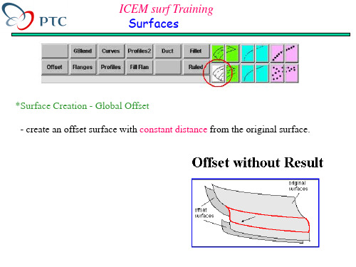
*Surface Creation - Global Offset - create an offset surface with constant distance from the original surface.
ICEM surf Training Surfaces
Priority is set to Tangent : y-axis = surface normal z-axis is determined by the tangent of the spine curve
Priority is set to Vector : y-axis = surface normal x-axis is determined by the vector
Priority is set to Vector : x-axis = connection to the corresponding point on the second curve y-axis is determined by the vector
ICEM CFD 中文PPT教程 F2-WS1-TubeGlinkaV10

9/16/05
ANSYS AI*Environment V10
Inventory #002281
E2-7
缝合焊缝
#1
#3 #4
#9
9/16/05
定义单元尺寸:
#2
– Mesh -> Define Connectors -> Seam Weld
– 接受默认选项 Seam connector name
#6
9/16/05
ANSYS AI*Environment V10
注意: 黄线为独立的线, 在壳模型 里需要用到
注释: 在这个模型里拓扑已经建好 了, 但还需要打开线元素的显示选 项。
Inventory #002281
E2-4
设定网格尺寸
#1 #2
Workshop
#3 #5
给定单元尺寸:
– Mesh -> Set Curve Mesh Size – 采用 General模式, 以及 select curves(s) 拾取, 采用“a”
热键选择所有线 或者从几何工具栏里选择所有图标。
#6
9/16/05
#4
– 设置 Maximum Element size 为 6 – 默认: 接受其他默认选项 – 按下 Apply.
显示单元尺寸: – 右键单击 Curves – 打开 Curve node Spacing 或 Curve Element Count
9/16/05
ANSYS AI*Environment V10
Inventory #002281
E2-6
首先延伸面
#1
Workshop
- 1、下载文档前请自行甄别文档内容的完整性,平台不提供额外的编辑、内容补充、找答案等附加服务。
- 2、"仅部分预览"的文档,不可在线预览部分如存在完整性等问题,可反馈申请退款(可完整预览的文档不适用该条件!)。
- 3、如文档侵犯您的权益,请联系客服反馈,我们会尽快为您处理(人工客服工作时间:9:00-18:30)。
应用ICEM Surf 的第一步
借用下面的介绍作为引言,我们将介绍应用该程序所需的基本的功能,也就是生成和编辑几何元素。
你可以按照下面的操作一步一步执行。
同时,还将介绍完成这项任务的用户界面的普通功能,还有关于该软件的习惯用法的信息。
任务
原始数据资料轮廓和曲线的生成
在新的项目存储基本资料
曲线的编辑和检测
移动几何物体
永久保存工作的状态
通过曲线构造Patch面
Patch面的检测和编辑
关于ICEM Surf 的结束语
任务
对原始资料处理可以得到断面线。
然后你可以编辑、复制、转换这些断面线。
你也可以生成曲面(即Patch)并编辑。
同时,应用检测功能可以检测曲面与断面线之间的符合情况。
原始数据资料和曲线的生成
·生成新的存储资料(查看生成新的存储资料)
·用这些存储数据生成近似的、光顺的原始资料轮廓(查看生成原始数据和曲线)
通过下拉菜单
1、激活Create和Modify按钮,选择需要的操作
2、激活需要的几何功能
通过几何功能按钮
图一
1、激活左边的生成元素按钮和右边的编辑元素按钮
2、单击需要的操作按钮
生成新的存储资料
生成原始数据和曲线
编辑显示参数
删除几何元素
生成新的存储资料
1、单击 File – New
2、在Save Current Data Base?对话框中确定“yes”or“no”,如果
需要重新建立文档选择“no”。
一个新的空白资料将作为当前存储资料。
生成原始数据和曲线
1、在功能菜单中(侧边)单击XZ平面,作为视图和工作平面
2、单击按钮"Create Raw Data"
3、单击Express
在视图范围内按住右键拖动光标延轨迹线生成Create Data数据。
4、单击Smooth
将Raw Data 转换成Curve线并光顺。
5、如果需要可以在Step Size中修改步距值,贴接曲线贴和Raw
Data的程度,默认值是25。
原始数据轮廓以控制点多边形显示
图二
编辑显示参数
1、单击Display
2、设置里面的参数为显示还是关闭
删除几何元素
数据类型
Molecule Type Atom Type
Surface
Patches and Faces
Curve
Curve segments
Raw Data Contour Raw data segments Point Set Points Scan Set
Scans
图三
存储数据
编辑和检测曲线
你可以应用Create - Raw Data - Express, Smooth曲线,这时曲线轮廓、曲线和控制点多边形都会显示在屏幕上(如图二)。
·冻结当前工作状态
·编辑曲线(查看编辑曲线控制点),通过检测查看调整的效果(查看曲线的检测)
·关闭曲线检测(查看关闭曲线检测),通过调整控制点使曲线与原始资料靠近(查看使曲线贴和原始资料)
·删除原始资料(查看删除个别的原始资料)
冻结当前工作状态
曲线的曲率检测
1、单击Diagnos
2、激活Diagnoses对话框中的Curvature
3、在Scaling中输入50
4、单击Curve按钮
5、下面的信息栏中出现Pick Segments/Edges.信息,选择曲线
或边界。
可以选择一个或几个参数进行检测。
1)鼠标单击需要显示的元素
2)通过键盘微调或框选。
6、进行其他操作前取消该操作
1)单击ok
2)单击鼠标中键
显示曲线的曲率检测结果
图四
你可以在Diagnosis – Curvature对话框中编辑参数,重新显示结果,直到确认。
编辑曲线控制点
1、单击"Modify Curve Segment"
2、单击CtrlP
3、在Control Point对话框中选中Express
4、选取曲线
5、选取控制点
选取控制点时按住左键不动
6、拖动控制点到一新的位置放开左键
如果必要,在调整控制点时候打开Diagnosis – Curvature改变曲率比例数值,显示曲率的调整效果。
图五
关闭曲率检测对话框
1、关闭Diagnosis – Curvature对话框
2、在Diagnoses对话框中单击按钮On/Off关闭显示
3、关闭Diagnoses对话框
在任何时候都可以单击On/Off来显示或消隐去率。
调整曲线使与原始资料贴和
1、关闭曲率显示
2、Ctrl + R刷新屏幕显示
3、编辑控制点使与原始资料贴和
4、通过改Order改变曲线控制点
曲线与原始资料贴和示意图
图六
移动和复制几何体
1、单击图标Move
2、单击按钮Transl
3、拾取元素
4、输入移动参数
Duplicate选中表示复制几何体,否则移动几何体。
旋转和转换几何体
1、按住Alt键(或者Shift键)
2、按住鼠标左键旋转几何体
3、按住鼠标中键平移几何体
图七
通过曲线构造Patch面
1、单击"Create Patch"
2、单击Curves
3、拾取边界选择两条曲线
4、在对话框中Selection (Object)选ok确定所选取线
5、Edges对话框中单击ok,关闭该对话框
两条线做的patch面
图八
检测和编辑Patch面
·删除做面用到的曲线
·渲染Patch面,旋转平移光源
·编辑Patch面的控制点,检查曲率参数
·关闭渲染模式,对Patch面切断面线,编辑Patch面,直到与原始资料断面线误差在允许值范围内,且光顺。
渲染Patch面
1、单击Display
2、关闭Selected复选框,打开或关闭Shading复选框。
3、确认设置后单击OK,关闭Display对话框
4、利用鼠标左键和右键旋转或平移光源
编辑Patch面的控制点
1、单击"Modify Patch"
2、单击CtrlP
3、激活Express
4、拾取曲面
5、设置U、V值。
对Patch面切X、Y、Z断面线
1、激活Sections功能键
2、对三个方向切线
3、关闭对话框
图九
关闭ICEM Surf 程序
1、选择File – Quit
2、在Terminate ICEM Surf对话框中单击DB Save
3、单击ok
4 . 1几何建模步骤
利用"Unified Modeling"模块建模
图十
4.2下面的步骤是应用"Unified Modeling"模块进行建模
1、
图十一
·选择物体
图十二
·生成物体
生成闭合Array
曲线
图十三
·定义显示属性
图十四
4.3编辑几何体和参考体
1、
图15 2、改变Order值
图16
2、Segmenting or dividing curves, patches, and faces
3、gmenting, dividing, refining, and filtering raw data
4、光顺曲线
5、光顺原始数据
6、动态光顺scans
7、编辑Face面
7、为face面定义拓扑关系
4.4 1、
定义几何体和参考体
定义拓扑关系执行拓扑
诊断定义物体刚度
定义几何体与参考体关系
图2、
定义拓扑关系
既产生拓扑关系又相贴合
图4.4.2
3、 执行拓扑诊断
图4.4.3
4、
定义刚度
图4.4.4 5、几何体与参考体之间定义关系
图4.4.5
4.5
1、。
