超声波水表使用手册
超声波水表使用说明
超声波水表使用说明第一部分:引言超声波水表是一种应用超声波技术进行水量测量的智能仪表。
相比传统的机械水表,超声波水表具有精确度高、反应速度快、维护方便等优点。
本文将详细介绍超声波水表的使用方法和注意事项。
第二部分:超声波水表的安装超声波水表的安装需要遵循以下步骤:1. 清除安装位置的杂物和污垢,并确保安装位置平整稳固。
2. 将超声波水表与水管连接,确保连接处无漏水现象。
3. 打开水源,检查水表是否正常工作。
第三部分:超声波水表的使用方法超声波水表的使用方法如下:1. 用干净的布擦拭超声波水表的外壳,确保表面干净无尘。
2. 打开水龙头,水流经过超声波水表时,水表将开始工作并进行测量。
3. 超声波水表会自动记录水流量,并在表面显示当前的用水量。
4. 可以通过按键或旋转盘来切换显示模式,例如显示总用水量、流速等。
第四部分:注意事项在使用超声波水表时,需要注意以下事项:1. 避免超声波水表长时间暴露在阳光直射下,以防止温度过高影响其正常工作。
2. 定期清洁超声波水表,以防止灰尘和污垢堆积影响测量精度。
3. 如发现超声波水表异常,如显示不正常或测量值异常等情况,应及时联系专业人员进行检修或更换。
4. 注意超声波水表的防水性能,避免水流进入内部造成损坏。
第五部分:总结超声波水表是一种高精度、快速响应的水表,使用方法简单,但仍需注意安装和使用过程中的细节。
合理使用超声波水表可以提高水资源的利用效率,减少浪费,为环境保护和节能做出贡献。
超声波水表的使用说明包括安装、使用方法和注意事项等方面。
通过正确的安装和使用,我们可以充分利用超声波水表的优势,实现对水资源的有效管理和节约使用。
希望本文对超声波水表的使用者有所帮助。
TDS-100超声波流量计说明书

§1.1 引言 (1)§1.2 工作原理 (1)§1.3 主板电气原理框图 (2)§1.4 特点 (2)§1.5 性能参数 (3)§1.6 用途 (4)二产品介绍 (5)§2.1 变送型超声波流量计/热量计 (5)§2.2 经济型超声波流量变送器 (6)§2.3 超声波流量/热量变送模块 (7)§2.4 固定分体式超声波流量计/热量计 (8)§2.5 一体管段式超声波流量计/热量计 (9)三本地显示及操作 (11)§3.1 本地段式LCD显示及操作 (11)§3.2 本地LCD显示器显示内容一览表 (12)§3.3 本地显示状态代码及故障判断 (12)四并口及串口键盘显示及操作 (14)§4.1 并口键盘 (14)§4.2 串口键盘 (14)§4.3 按键功能 (14)§4.4 窗口操作 (14)§4.5 菜单分类 (16)§4.6 菜单一览表 (16)§4.7 菜单窗口详解 (19)§4.8 菜单设置特别说明 (44)五传感器安装 (46)§5.1 开箱检查 (46)§5.2 供电电源及电缆线 (46)§5.3 安装必备条件 (46)§5.4 快速输入管道参数步骤 (48)§5.5 外缚式传感器的安装方法 (50)§5.6 插入式传感器的安装方法 (52)§5.7 管段式传感器的安装方法 (56)§5.8 用户自备外缚传感器参数及其输入 (59)§5.9 通电 (59)§5.10检查安装 (59)六热量测量 (61)§6.1概述 (61)§6.2 PT100电阻的接线 (61)§6.3有关温度测量的一些菜单说明 (61)§6.4温度测量子系统的标定 (62)§6.5有关热量测量量值的输出 (63)七故障解析 (63)九输入输出回路及其使用 (67)§9.1怎样使用4-20mA电流环输出 (67)§9.2怎样输出模拟电压信号 (68)§9.3这样使用频率信号输出 (68)§9.4怎样输出累积脉冲 (68)§9.5怎样产生输出报警信号 (68)§9.6怎样使用蜂鸣器 (69)§9.7怎样使用OCT输出 (69)§9.8怎样使用继电器输出 (70)§9.9怎样连接压力信号和液位信号(模拟输入) (70)§9.10模拟输入的校准 (70)§9.11联网时模拟输入量的读取 (71)十质量保证及服务维修支持 (72)§10.1质量保证 (72)§10.2公司服务 (72)§10.3产品升级 (72)§10.4技术咨询 (72)十一附录 (73)§11.1常用液体声速和粘度 (73)§11.2常用材料声速 (73)§11.3水中声速表(1标准大气压下) (74)一概述§1.1 引言欢迎您使用大连正工仪表设备有限公司研制生产的新一代TDS-100系列超声波流量计/超声波热量计/流量变送器。
WATERINFORMATION(超声波水表说明书)

WATERINFORMATION(超声波水表说明书)CUTE-LV SERIES ULTRASONICWATER METERPRODUCT INTRODUCTIONCHANGZHOU CUTE INTELLIGENT CO.,LTD1、OverviewCUTE serial ultrasonic water meter module is the core part to work with the base meter to measure and display the water flow.CUTE serires ultrasonic water meter with the M-BUS interface, The staff can read the meter data at any time by the remote reading management system with the M-BUSinterface and other device.2、Function and Characteristic 2.1 Under voltage warning;2.2 Automatic error correction tech;2.3 Temperature sensor cut and short circuit warning; 2.4 Flow sensor failure warning;2.5 High definition and wide temperature LCD; 2.6 Wide range ratio;2.7 Lithium battery life is more than 6+1;2.8 Can read the meter data by infrared tool at the spot; 2.9 With the M-BUS interface;3、Usage instruction1.The water meter operated by the menu, can change the work condition and display contents by the button on panel;There are 4 menu, the default is main menu, the change flow is as below:Means the long press time >2s;1) Main menu: normal condition; 2) Error menu 【E 】3) Information menu 【I 】 4) Verification program 【F 】The screen is off when stand by, press the button to awake the meter and enter the m ain menu, which show the accumulated flow(above figure), long press to change menu and read the data you need, the screen will be off after 3 minutes without any operation except the verification program 【F 】.Main MenuMain menuxxxxx.xxx m 3【E 】【I 】【F 】Error menu operation 【E 】Press<2s Long press>2sXXXXX.XXX m 3XX.XXX m 3/h AccumulationXXXXXXXX hDN20X.X.X.X.X.XXXInstant flowWork timeTypeFull screen 【E 】1 XX.XX.XX Battery fault (date)Accumulated timeInformation Menu 【I 】Verifivcation Menu 【F 】Press<2sLong press >2s【F 】 XXX.XXXXX m 3FXXX.XXXXX m 3/h F℃ XX.XX Zero clearWater temperature 瞬流 Instant flowAccumulated flow5 XX.XX.XX S6 XX.XX.XX S7 XX.XX.XX STranducer fault flow in (date)Tranducer fault flow out (date)换能器故障出水端发生日期(年月日)8 XX.XX.XXS7 XXXXXXX h8 XXXXXXX hXXXXXX XXXXXXXXXXr XX d -xx.xx.xx Y M D xx.xx.xx H M S 【I 】Main add Second addEditionPresent datePresnet time Last month Readingr-xx.xx.xx Y M DXXXX.XXX m 3Last 2 months Reading4、Characteristics:Accumulated volume definition 0.001m 3 (working )0.00001m 3(verifying )Present flow definition 0.001 m 3/h (working ) 0.001 m 3/h (verifying ) Measure range Q 3/Q 1=400 Quiescentcurrent < 6uABattery life > 6+1 year LCD digits 8Max accumulatedtime4.2x109 hoours (work time>99999999, only display the last 8 valid digits )Max accumulated flow4.2x109m 3 (flow>99999.999 m 3 ,only display the last 8 valid digits )Accuracy class II class5、Failure analysis and solution No. Problem Cause Solution 1 Battery fault Under vlotage or bad connection Check the connector, changethe battery;2 Vacant pipe fault No water or not full in the pipe Fill the pipe full andeliminate the bubble3 Reflux fault The inflow and outflow reverse Adjust the inflow andoutflow4 Surpass range ratio The present instant flow is too high Lower the flow or change themeter 5 Water temperature Water temperature fault Lower the temperature orchange the meter 6 EE fault EE storage invalid Change the PCB 7 Transducer Inflow Change or reinstall thePress<2s Long press>2s 按大于2秒Remark :Under the verification menu, the accumulated flow and heat can be zero clear automatically, when the flow rate is 0,,if detect the flow rate in pipe is higher than the set point, zero clear the present accumulated data; When can't make zero clearunder some extrem conditio, which can be done by manual;Exit the verification menu without any operation in 2 hours;transducer8 Transducer OutflowChange or reinstall thetransducer6、PCB connector and outlineNote :Please read the documents carefully before using the products; If any qutstion, please don ’t hesitate to contact with us;Special instruction for the verification mode(1).Enter the verificaiton modeAfter turning on the water meter, press the button until seeing the 【F 】,then press again to see the below content :Accumulation Flow0.00000 m3ButtonLCDBattery connectorMain menuKW·h 【E 】【I 】【F 】Verification(2).Menu clausePress the button every time, you will see the caluse in order, please see thedetails in page 6;(3).NoteUnder the verification mode, the accumulated flow can be zero clear automatically,when the flow rate is 0, it will be zeroclear and start a new flow inspect automatically;。
LRW-2000 双声道超声波水表说明书

LRW-2000 双声道超声波水表
1. 概述
§ 1.ห้องสมุดไป่ตู้ 引言
LRW-2000 系 列 水 表 是 依 据 中 国 国 家 水 表 标 准 GBT/778.1-2007 、 国 际 水 表 标 准 ISO4064-1:2005,IDT 等标准研发生产的产品。
该水表采用了公司最新开发的特有的超声波传播相位与时差测量技术,具有精度高,耗 电小、测量量程比宽、稳定可靠等显著特点。
5. 怎 样 使 用 ........................................................ - 24 -
§ 5.1 怎样修改计量单位 ....................................................................................... - 24 § 5.2 怎样修改累积量的小数点位置 ..................................................................... - 24 § 5.3 怎样重新设定年月日时分秒星期几 .............................................................. - 24 § 5.4 怎样确认水表是否工作完全正常(利用工作状态码快速诊断问题所在) ..... - 24 §5.5 怎样使用标定用专用窗口............................................................................. - 24 § 5.6 怎样使用内置的定量控制器 ......................................................................... - 25 § 5.7 怎样修改分时累积器的时间点 ..................................................................... - 26 § 5.8 怎样修改通讯地址 ....................................................................................... - 27 §5.9 怎样重新设定 M-BUS 第二地址................................................................... - 27 § 5.10 怎样修改红外通讯速率 .............................................................................. - 27 §5.11 怎样修改 RS485/M-bus 通讯速率 ............................................................. - 28 -
超声波水表使用说明
超声波水表使用说明超声波水表是一种先进的计量设备,通过超声波技术实现对水流量的精确测量。
本文将为您详细介绍超声波水表的使用方法和注意事项,以确保您能正确、方便地使用超声波水表。
一、安装与连接1. 在安装超声波水表之前,请确保水表安装位置没有任何障碍物,并且具备稳定的水流条件。
2. 将超声波水表安装在水管上,确保连接口紧固,并使用密封胶垫进行密封,以防止漏水。
3. 连接超声波水表与数据采集设备或智能终端,确保连接稳定可靠。
二、使用方法1. 打开水源后,超声波水表会自动开始工作。
您可以通过观察显示屏上的数据来实时了解水流量。
2. 您可以通过按下水表上的按键来切换显示屏上的信息,如总累计流量、瞬时流量、温度等。
3. 如果需要查看更多详细信息或进行设置,您可以使用数据采集设备或智能终端连接超声波水表,并通过对应软件进行操作。
4. 超声波水表具有自动检测功能,当出现故障或异常情况时,水表会自动报警,并显示相应的错误代码。
请及时联系售后服务。
三、注意事项1. 在使用超声波水表之前,请阅读并理解产品说明书。
确保您具备基本的操作知识和安全意识。
2. 超声波水表应安装在通风良好的环境中,避免阳光直射、高温、潮湿等影响测量精度的条件。
3. 定期清洁超声波水表的显示屏和外壳,确保清晰可见,并避免灰尘或污物进入水表内部。
4. 超声波水表具有较高的精度和灵敏度,请避免碰撞或摔落,以免影响正常使用。
5. 如需维修或更换超声波水表,请联系正规渠道的售后服务,切勿自行拆卸或修理。
总结:超声波水表是一种先进的计量设备,通过超声波技术实现对水流量的精确测量。
在安装和使用超声波水表时,我们需要注意安装位置、连接稳固、操作方法以及日常维护等方面的事项。
只有正确、规范地使用超声波水表,我们才能准确地了解和管理水资源的使用情况,做到节约用水、科学用水。
如果在使用过程中遇到问题或需要维修,应及时联系售后服务,切勿私自拆卸或修理。
通过正确使用超声波水表,我们可以更好地保护环境、节约资源。
超声波水表使用手册范本

超声波水表使用手册感选用TPP-70SW系列超声波水表。
TPP-70SW系列超声波水表是基于超声波时差法原理设计而成的性能卓越的超声波测流产品。
本公司对TPP-70SW系列超声波水表拥有完整的、独立的知识产权。
使用过程中如有任何问题,欢迎来电来函。
执行标准:生产标准:中华人民国国家标准GB/T778-2007《封闭满管道中水流量的测量,饮用冷水水表和热水水表》检定标准:中华人民国国家计量检定规程JJG162-2009《冷水水表》重要提示:1、使用前请详尽阅读使用手册,并妥善保管使用手册,以备查阅;2、本产品为精密测量仪器,在安装与使用过程中尽量远离干扰源,选择合理的安装位置,并避免严重撞击、碰撞;3、本产品出厂前均经过严格的质量检测,严禁非规性操作或私自拆卸,否则后果自负;4、显示图案、提示等均为窗口操作提示,并不能作为产品检定依据;5、产品检定,请选择符合国家计量要求,正规的流量检定装置,并严格按照规操作;6、TPP-70SW会不定期进行升级,产品实际功能与本手册不一致时,请以实际产品为准或向厂家咨询;7、出现错误提示时,请及时联系厂家或经销商,否则会造成流量损失。
一、产品特点:专门用于小区分户或其它场所的小口径用水的精准计量;最小可测流速仅为0.003m/s,真正实现滴水计量;可实现正反流量的双向计量;双行同屏显示,完整的提示功能,方便查询、诊断;机身可自由近360度旋转,方便用户查阅;小体积微功耗设计,实际使用寿命10年以上;优良的线性度,在满量程围,线性一致,无须多点校正;完美的软件扩展功能,可满足不同用户的定制要求;多种计量单位可选,满足不同国家的用户需求;二、产品外形尺寸公称直径(mm) L(mm) H(mm) W(mm) 连接螺纹DN15 110 68.5 90.5 G3/4B DN20 130 85 90.5 G1B DN25 175 93.5 90.5 G1 1/4B三、产品技术参数特性技术参数可测介质水及其它均质液体且充满被测管段准确度等级优于2级最大允许工作压力 1.6Mpa公称通径DN15-DN25工作环境温度:-15~55℃;湿度≤100%(RH)温度等级T30/T50, 出厂默认为T30上游流场敏感度等级U10下游流场敏感度等级D5气候和机械环境安全等级C类电磁兼容性等级E1数据存贮EEPROM/FLASH存储数据数据通讯RS485/红外工作电源 3.6V锂电池,寿命10年防护等级IP68本地显示双行显示9位累积量、4位瞬时流量及流量单位、状态提示符四、流量围公称直径 (mm) 量程比(Q3/Q1)R 始动流量(L/H)最小流量 Q1 (L/H) 分界流量 Q2 (L/H) 常用流量 Q3 (m³/H ) 过载流量Q4 (m³/H ) DN15 400 6.25 10 2.5 3.125 DN20 400 10 16 4 5 DN2540015.7525.26.37.875五、窗口操作用磁棒触碰磁感应区即可实现显示窗口的切换、循环。
WATER INFORMATION(超声波水表说明书)
CUTE-LV SERIES ULTRASONICWATER METERPRODUCT INTRODUCTIONCHANGZHOU CUTE INTELLIGENT CO.,LTD1、OverviewCUTE serial ultrasonic water meter module is the core part to work with the base meter to measure and display the water flow.CUTE serires ultrasonic water meter with the M-BUS interface, The staff can read the meter data at any time by the remote reading management system with the M-BUSinterface and other device.2、Function and Characteristic 2.1 Under voltage warning;2.2 Automatic error correction tech;2.3 Temperature sensor cut and short circuit warning; 2.4 Flow sensor failure warning;2.5 High definition and wide temperature LCD; 2.6 Wide range ratio;2.7 Lithium battery life is more than 6+1;2.8 Can read the meter data by infrared tool at the spot; 2.9 With the M-BUS interface;3、Usage instruction1.The water meter operated by the menu, can change the work condition and display contents by the button on panel;There are 4 menu, the default is main menu, the change flow is as below:Means the long press time >2s;1) Main menu: normal condition; 2) Error menu 【E 】3) Information menu 【I 】 4) Verification program 【F 】The screen is off when stand by, press the button to awake the meter and enter the m ain menu, which show the accumulated flow(above figure), long press to change menu and read the data you need, the screen will be off after 3 minutes without any operation except the verification program 【F 】.Main MenuMain menuxxxxx.xxx m 3【E 】 【I 】 【F 】Error menu operation 【E 】Press<2s Long press>2sXXXXX.XXX m 3XX.XXX m 3/h AccumulationXXXXXXXX hDN20X.X.X.X.X.XXXInstant flowWork timeTypeFull screen 【E 】1 XX.XX.XX Battery fault (date)Accumulated timeInformation Menu 【I 】Verifivcation Menu 【F 】Press<2sLong press >2s【F 】 XXX.XXXXX m 3FXXX.XXXXX m 3/h F℃ XX.XX Zero clearWater temperature 瞬流 Instant flowAccumulated flow5 XX.XX.XX S6 XX.XX.XX S7 XX.XX.XX STranducer fault flow in (date)Tranducer fault flow out (date)换能器故障 出水端 发生日期(年月日)8 XX.XX.XXS7 XXXXXXX h8 XXXXXXX hXXXXXX XXXXXXXXXXr XX d -xx.xx.xx Y M D xx.xx.xx H M S 【I 】Main add Second addEditionPresent datePresnet time Last month Readingr-xx.xx.xx Y M DXXXX.XXX m 3Last 2 months Reading4、Characteristics:Accumulated volume definition 0.001m 3 (working ) 0.00001m 3(verifying )Present flow definition 0.001 m 3/h (working ) 0.001 m 3/h (verifying ) Measure range Q 3/Q 1=400 Quiescentcurrent < 6uABattery life > 6+1 year LCD digits 8Max accumulatedtime4.2x109 hoours (work time>99999999, only display the last 8 valid digits )Max accumulated flow4.2x109m 3 (flow>99999.999 m 3 ,only display the last 8 valid digits )Accuracy class II class5、Failure analysis and solution No. Problem Cause Solution 1 Battery fault Under vlotage or bad connection Check the connector, changethe battery;2 Vacant pipe fault No water or not full in the pipe Fill the pipe full andeliminate the bubble3 Reflux fault The inflow and outflow reverse Adjust the inflow andoutflow4 Surpass range ratio The present instant flow is too high Lower the flow or change themeter 5 Water temperature Water temperature fault Lower the temperature orchange the meter 6 EE fault EE storage invalid Change the PCB 7 Transducer Inflow Change or reinstall thePress<2s Long press>2s 按大于2秒Remark :Under the verification menu, the accumulated flow and heat can be zero clear automatically, when the flow rate is 0,,if detect the flow rate in pipe is higher than the set point, zero clear the present accumulated data; When can't make zero clear under some extrem conditio, which can be done by manual;Exit the verification menu without any operation in 2 hours;transducer8 Transducer OutflowChange or reinstall thetransducer6、PCB connector and outlineNote :Please read the documents carefully before using the products; If any qutstion, please don ’t hesitate to contact with us;Special instruction for the verification mode(1).Enter the verificaiton modeAfter turning on the water meter, press the button until seeing the 【F 】,then press again to see the below content :Accumulation Flow0.00000 m3ButtonLCDBattery connectorMain menuKW·h 【E 】 【I 】 【F 】Verification(2).Menu clausePress the button every time, you will see the caluse in order, please see thedetails in page 6;(3).NoteUnder the verification mode, the accumulated flow can be zero clear automatically,when the flow rate is 0, it will be zero clear and start a new flow inspect automatically;。
wPrime 280W-R超声波水表用户手册和安装指南说明书
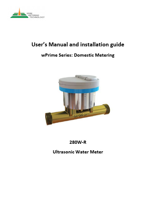
User’s Manual and installation guide wPrime Series: Domestic Metering280W-RUltrasonic Water Meter1.General information (3)1.1.Introduction: (3)1.2.General Safety: (3)1.3.Unpacking and Package Contents: (4)2.Technical Information (5)2.1.Automatic Meter Reading: (5)2.2.Built-in Time-Keeper (5)2.3.Battery Specifications (5)2.4.Product Measurement Method (5)2.5.Specifications (6)3.Operation (8)3.1.Built-in Battery (8)3.2.Power On (8)3.3.Menu Windows (8)4.Installation (10)4.1.Installation Directions (10)4.2.Site Selection: (10)4.3.Installation Position and Location: (10)4.4.Operations Check (12)5.Troubleshooting (13)5.1.Powers-On Errors (13)5.2.Other Problems and Solutions (13)6.Interface/Communication (15)6.1.Pulse Output (15)6.2.M-Bus/BACnet Output (15)6.3.Analog Output 4-20mA (17)6.4.Modbus Output (17)6.5.Wireless Output (19)1.General information1.1. Introduction:Thank you for your purchase of the 280W-R. One of the most prominent meters in the wPrime series, the 280W-R is an ultrasonic water meter that uses advanced technology based on the ultrasonic transit time principle. The water meter does not have moving parts; therefore there is no need to worry about maintenance and replacing worn out parts. In addition, the accuracy remains constant over time.The 280W-R is suitable for both commercial and industrial applications. The meter features a remote read-out (pulse, M-Bus, RS485 output, BACnet or Wireless). When equipped with an M-Bus module, the water meter can be networked through a two-wire bus to a central location for integrated resource management. An optional concentrator and data acquisition software make the whole system installation and integration easy. Spire Metering provides a complete AMR (automatic meter reading) solution as well.1.2.General Safety:Before installing your new 280W-R please consider the following:•Read this instruction guide carefully and follow the factory directions.•Injury or damage may occur if the user doesn’t read and understand this installation guide.•Consider handling and lifting instructions to avoid damage.•Never hold and transport the meter by the electronics box, but instead only by the flanged or threaded joint•Assembling and dismantling should be performed only when there is no pressure in the pipe •Beware of sharp edges•After installation, the tightness must be verified by pressurizing with cold water•Use the meter only under the specified operating conditions. When conducting the pressure test, make sure the pressure does not exceed 2.5MPa. Otherwise, dangers may arise and will void the warranty•The 280W-R water meter is not certified for use in hazardous environments. The local site safety codes and regulations must be observed.•The 280W-R water meter contains Lithium batteries. Please check to see if they’re working before using the water meter. The batteries must be recycled or disposed of properly.1.3.Unpacking and Package Contents:Your new 280W-R meter has been fully tested and calibrated. After carefully unpacking please inspect the meter for shipping damage. You should also have the following:•The 280W-R meter (flowcell body and the integral electronic display).•The installation Guide.•Certificate of calibration.2.Technical Information2.1.Automatic Meter Reading:AMR is a system that can be used for MBS (building management) or other networks. When equipped with a connection module, multiple 280W-Rs can be networked through a two-wire bus to a central location for integrated resource management. Spire Metering Technology provides an entire system of AMR solutions, making the system installation and integration very easy.The SpireCapture TM system is a cutting-edge fixed AMR system which integrates both wired and wireless AMR/AMI technologies. It can accommodate a variety of metering networks, such as M-Bus, Pulse, RF wireless, GSM/GPRS, BACnet module, and TCP/IP. The data center software communicates with those networks through a standardized platform, which allows you to start with a simple AMR system and gradually expand to a larger metering system.2.2.Built-in Time-KeeperA time-keeper is integrated into the 280W-R meter. The time-keeper remains operating as long as the battery is alive. In case of battery failure, the time-keeper will not keep running, and the time data will be lost. The user must re-enter the proper time values after the battery failure is recovered. The user can also set the date and time as desired.2.3.Battery SpecificationsLithium-Thionyl Chloride type batteryNominal Capacity: 19 AhNominal Voltage: 3.6VMax Recommended Continuous Current: 100mAMax Pulse Current Capability: 200mAOperating Temperature Range: -55°C (131°F) to 85°C (185°F)2.4.Product Measurement MethodThe measurement principal is based on ultrasonic transit time technology. The sensors, located in the meter’s body, send and receive the ultrasonic signal. The transit-time difference is processed by a strong signal processing signal in order to display the flow velocity and the volume.The ultrasonic water meter is a battery-powered precision flow meter designed for bidirectional flow measurement of water. The water meter can be used for a wide range of applications.2.5.SpecificationsNotes:• Default pipe joint is BSP threading.• NPT threading is available upon request.• L is flow sensor length. L1 is the total length of flow sensor plus extension pieces. • Weight includes extension piece. It may vary. Please contact us for exact measure. • 1m3/h is about 4.4GPM.• Dimension H, Φ1 and Φ2 are for reference only. Please contact us for exact measure.ApprovalsOIML R49, ISO 4064, NSF61-G, MID BElectrical DataPower Supply: Battery, 3.6V, LithiumReplacement Interval: >10 years at tBAT<30°C (86°F) based on one remote reading perday.Power Consumption: <0.1WBackup Power Supply: Internal SuperCapCommunication Interface: M-Bus (default). Optional: RF 433MHz or RF 868MHzwMBus*, RF 470MHz long range, Encoder or ModbusCE approval: EN61326-1:2006Electromagnetic Class: E2Accuracy / MPE (Maximum Permissible Error)MPE according to ISO 4064: 2005 or OIML R49±2 in the range Q2 ≤Q < Q4; ±5 in the range Q1 ≤Q ≤Q2 [for T ≤ 30ºC (85ºF)]±3 in the range Q2 ≤Q < Q4; ±5 in the range Q1 ≤Q ≤ Q2 [for T > 30ºC (85ºF)]Dynamic Range: 250 (For others please contact SpireMT)Mechanical DataMetrological Class: 2 (according to ISO 4064: 2005 or OIML R49) Environmental Class: B / CEnvironmental Temp: 0 ~ 60°C (32 ~ 140°F)Permissible Flow Temp: 0.1 ~ 60°C (35 ~ 140°F) for long term and up to 85°C (185°F) for<24 hours.Enclosure Protection: IP68Integrator Detachable: NoPressure: PN16Pressure LossThe pressure loss of a flow sensor is proportional to the square on the flow: Δp = k x Q2Here Δp is pressure loss, Q is volume flow rate and k is the coefficient.The DN15 (½”) meter has k=0.067 and Δp less than 0.48bar at Q3.The DN20 (.”) meter has k=0.019 and Δp less than 0.27bar at Q3The DN25 (1”) meter has k=0.006 and Δp less than 0.23bar at Q3.The pressure loss for all sizes meet the ISO 4064: 2005, OIML R49 standards.3.Operation3.1.Built-in BatteryThe instrument operates from the built-in Lithium battery, which is long-lasting… up to 10 years of operating time. For more details about the battery please refer to the battery specifications section 2.3. If your 280W-R is connected to an outside power source, such as M-Bus, the meter will not use the battery but instead draw power directly from the M-Bus.Due to transport regulations, the battery might be deactivated by an insulating strip, which must be removed completely in order to activate the meter. If a replacement battery is needed, please contact your representative or Spire Metering. If the meter needs to be sent by air freight, then the battery will be removed prior to shipping.For safety precautions, the batteries should not be opened, come into contact with water, or be exposed to temperatures above 80 °C (176°F). Batteries should be disposed of at proper collection centers.3.2.Power OnFirst, make sure to activate the battery and that the display will turn on. If the meter LCD is on, the meter is active already and no further action is needed. Generally, there should be no error messages, and the water meter will cycle between the total volume and the flow rate.The flow measurement program will always operate in the background of the user interface. This means that the flow measurement will keep running regardless of any user window browsing or viewing.Once it is turned on, the 280W-R will keep on running until its battery runs out. There is no need to turn off the device when not in use; the display will turn off by itself to save the battery.3.3.Menu WindowsThe user interface of this 280W-R water meter has several windows displays that can be viewed. The water meter calculates the results and updates the display constantly. The menus are displayed in loop-fashion. The following values can be displayed:•Total Volume (m3)•Flow rate (m3/h)•Serial number (ID)These are the top layer (A1-layer) of the menu display structure. On the second layer (A2-layer) of this structure, more information can be seen. To go from the A1-layer to the A2-layer, the user will need factory software tool change the LCD display. On the A2-layer, the following menus are displayed:•Total Volume with High Resolution (5 decimals)•The current time•The error code•Factory data 1•Factory data2, followed by meter size•Meter size•Factory data3•Factory data4•Flow rate (m3/h)Note: Factory Data 4 and Factory Data 5 are the calibration coefficients for Q1 (normal flow rate), Q2 (0.2 times normal flow rate), Q3 (0.1 times normal flow rate), and Q4 (minimum flow rate).Example: If Menu Factory Data 4 shows 626C 63CE, then the coefficient for Q1is626C (Hex) or 25196 (Dec), and the coefficient for Q2 is 63CE (Hex) or 25550 (Dec). Similarly, this applies to Factory Data 5.4.Installation4.1.Installation DirectionsThe water meter body should be completely full at all times for proper flow measurements. When this is not the case, it will show a loss of signal and the meter will not measure. The signal will be restored as soon as the pipe is full again.FLOW DIRECTION: The 280W-R is a one directional water meter. Note the indicating arrow for forward flow. Even though the meter can measure the reverse flow, however, the accuracy for reverse flow measurement is not guaranteed.Spire Metering recommends keeping the lid closed in case of direct sunlight exposure. However, no direct damage will occur while the lid is open temporarily.Do not expose the meter to excessive vibration. To prevent this from occurring, support the connection pipe spools on both ends of the water meter.To avoid measuring errors and malfunctioning of the flow meter due to air or an empty pipe, please observe the following precautions:• Installation of the flow meter should be at the lowest point of the system, if possible, since air will be built at the highest point of a system.• If possible, maintain positive back pressure in meter outlet piping.• In order to avoid cavitation, always install control valves downstream of the flow meter and never install the flow meter on a pump suction side.4.2.Site Selection:Find a suitable location for connecting the flow cell (the “tube” part of the device where water flows through) to the pipeline.•Do not install the meter within 0.5m of an AC power line or a high-frequency radiation source.•It is highly recommended to have a 5D straight pipe run upstream and 2D straight pipe run downstream, where D stands for pipe diameter.•When two or more water meters are installed closely, make sure they are distanced by 5D or more.•Do not install where back flow or pressure fluctuations may occur. An alternative is to install a non-return valve to prevent the backflow. We do offer easy-to-install insertion****************************************************************.•When using a wrench, hold the metal part of the sensor.•When connecting to a pipe line, use an O-ring for the sealing. Make sure the O-ring is centered at the joining point. Otherwise, it could generate flow disturbance, thusdegrade the meter accuracy•The meter sensor can be installed vertically or horizontally: When it is installed vertically, make sure the flow goes upward When it is installed horizontally, the flow-cell should be installed in a way so that the display faces upward and the two ultrasonictransducers on the horizontal plane.4.3.Installation Position and Location:Please refer to the following diagrams for correct installation and handling.Correct installation of meter on U-configurationFor proper and accurate reading, flow should go against gravitySensor can be on the side after installationHandle the metal of the meter during installation4.4.Operations Check• After the installation is complete, the air in the pipe has to be purged out completely.•Make sure the pressure in the system is normal.•Use meter only under the specified operating conditions. Make sure flow rate range is proper for the pipe.•Important: The pipe must be full of liquids during operation![Pick the date]5.Troubleshooting5.1.Powers-On ErrorsWhen powered on, the 280W-R meter automatically starts the self-diagnosis process to see if there are any hardware or software problems. If a problem is identified, an error message will be displayed. The following are the possible error messages, the corresponding causes, and their solutions:If this error is displayed, it means there is no water flowingthrough the water meter. Check the pipe’s water supply and tryto get it so that the pipe is full of water.If this error is displayed, it means that the flow is reversed.If this error is displayed, it means that the signal is abnormal.If this error is displayed, it means that means the battery islow.5.2.Other Problems and SolutionsQ1: Why does the instrument display 0.0000 flow rate while the liquid in the pipe is actually flowing?A1: There might not be enough water in the pipe. Try to get it so that water flow through the flow cell is almost full. Additionally, check the installation to see if it is in a desirable location.Q2: The displayed flow rate is much lower or much higher than the actual flow rate in the pipe under normal working conditions. Why?A2: The flow cell and meter might have been installed incorrectly. Check the connection.The amount of straight pipe run upstream and downstream may be too small. This can cause the data reading to be inaccurate.When the meter sensor is installed vertically, make sure the water flow goes upward. When it is installed horizontally, make sure the ultrasonic transducers of the flow cell are on the side instead of the top or bottom, as this may skew results.[Pick the date]6.Interface/CommunicationThe 280W-R will have one of the many options output pre-selected when placing the order. This section will describe each output:Pulse Output (see section 6.1)Mbus output (see section 6.2)Modbus/Bacnet/RS485 output (see section 6.3)4-20mA output (see section 6.4).Wireless output (see section 6.5)6.1.Pulse OutputThis opto-isolated digital output is an open Collector type pulse. The allowable voltage range for the pulse is 5-24 VDC. The input impedance (Rx) is set at the factory to be 11 KOHM. Consult the instrument representative or Spire Metering if you are uncertain as to the proper diagram interpretation and wires details:The table below shows all the details about the pulse parameters by size:Pulse Parameters RangeDefaultvalue(<DN125)Defaultvalue(<DN250)Defaultvalue(<DN500)NoteUpdate time 8s~3600s 60s 60s 60sPulse width 20ms~1000ms 50ms 50ms 50ms Low pulse, duty ratio is 50%Pulse interval 100ms~1000ms 100ms 100ms 100ms It means the minimal time interval between two pulsesPulse volume1 10 100 100010000 100000 (L)1000 100 10Pulses per 100m³.Such as: 1000 means100L per pulse.6.2.M-Bus/BACnet OutputThe M-Bus uses two wire cables which are going from the M-Bus Master / Repeater to eachPulse wires outputM-Bus device (bus structure). The M-Bus is polarity independent and needs no line termination resistors at the end of the cables.Any cable type may be used as long as the cable is suitable for 42 V / 500 mA. Shielding is not necessary and not recommended since the capacity of the cable should be minimized.In most cases a standard telephone cable is used which is a twisted-pair wire with a diameter of 0.8 mm each (2 x 0.8 mm). This type of cable should be used for the main wiring. For the wiring to the meters from the main wiring (last 1 … 5 m to the meter) a cable with smaller diameter may be used.The M-Bus system is an European instrument “bus” standard designed fo r domestic metering devices, such as water meters, heat/water meters, gas meters, etc., to communicate with data centers. The “bus” simply uses two non-polarized wires to achieve a variety of options for reliable meter reading, remote diagnosis, remote control, incremental pricing, time-based pricing, batch service, prepaid billing, and more. This ‘bus’ system is both simple and economical to wire and implement.A typical M-Bus AMR system consists of a number of M-Bus utility meters, several M-Bus concentrators, a GSM/GPRS/LTE Data Transmitter Unit (DTU) for each M-Bus concentrator, and a data center. The M-Bus Concentrator communicates with the data center computer through a GSM/GPRS network. The data center first issues a meter reading command and sends it to the network. The DTU receives the command and forwards it to the M-Bus concentrator. Then, the concentrator either replies to the command with requested data or passes the command to its submeters transparently.Please note that you may not need the DTU unit if you can connect the M-Bus concentrator(s) to your computer directly. Alternatively, you may connect the concentrator(s) to your computer through TCP-IP network by using Ethernet-232 adapters. Similarly, you may connect the concentrator(s) to your BACnet or MODBUS network by using proper adapters.The 280C Concentrators are used for an AMR system to facilitate the communication between the data center and the M-Bus utility meters of the AMR system. These concentrators support up to 280 meters 280W-R. A wireless M-Bus concentrator is also available, where the M-Bus concentrator is affixed with a GSM/GPRS/LTE data transmitter unit (DTU).[Pick the date]6.3. Analog Output 4-20mAThe current pulse output is passive 4-20 mA. 4 mA is always “0” (zero) flow and the 20 mA is factory programmable at the max flow rate of the meter.Below is the diagram showing the wiring details: 6.4. Modbus OutputThe 280W-R meter is equipped with MODBUS serial communications to volume rate data, volume data in a variety of engineering units. You select the engineering units you wish to use by mapping to the appropriate registers.This document provides a suggested list of registers to use.MODBUS REGISTER FORMAT AND NETWORKING INFORMATIONMODBUS RS485, 2-wire (half-duplex) serial output is master/Slave communication architecture. The 280W meter is the slave.With the MODBUS module option, the 280W-R supports standard MODBUS protocol:• Baud Rate: 9600 bps • Checksum: None • Data bit: 8 bits •Stop bit: 1 bit1. All registers are 16 bit MODBUS Holding Registers.2. MODBUS Holding Registers are used in 4 different ways.• As an Analog Value: In some cases these values are scaled by multiplying theregister contents by a fixed multiplier.• As a status or mode indicator where the register value can be “1” or “2”...etc. • As a control register where the host can write a value.3. Registers 40001 through 4038 are described below in the registers table.4-20mA output diagram outputMODBUS REGISTER TABLENotes:*Unit code:32 – Litre/H; 2C – Cubic Meter;29 – Litre; 35 – Cubic Meter/H.Data Format:For LONG data, it has 32bits. Thus, two registers are used to store a LONG. The first register (lower address) is for the lower 16bits of the data. The second register (higher address) is for the higher 16bits of the data.** Use factory software to change the communication protocol. If you set the Communication Mode to 1, and set the duration to 6556, then the meter will switch to M-Bus protocol. Resetting the external power will switch the mode back to MODBUS protocol.6.5.Wireless OutputThe 280W-R has could be remotely monitored with its robust and reliable wireless module. This module can be RF (for short distances, less than 2K feet), GPRS, GSM or LTE. Each water meter will be accessible as long as GSM/GPRS/LTE network is available.All the data can be monitored and analyzed using our software.For details on the wireless interface, please consult with our tech support department by phone at +1 978-263-7100 or by email at *******************.。
超声波说明书内容

FUF-2000 基本型号
注: 开箱检查
FUF-2000P 系列便携式超声流 量表 FUF-2000-WJP1 外夹便携式 FUF-2000- WJP2 外夹笔记本便 携式 FUF-2000- WJP3 外夹手持式
FUF-2000F 系列在线式超声流量表
FUF-2000-FC 插入式 FUF-2000-FG 法兰式
OCT
OCT
RS232 接 口
模 拟
模 拟
一
继
继
电
电
电 23 5
源
+
输 出
输 出 一
集 电 级
发 射 级
器 输 出
器 输 出
+
模
模
模
模
上
上
下
下
拟
拟
拟
拟
游
游
游
游
电输
输
输
输
模
模
探
探
入
入
入
入
头
头
地
头
头
源地
3;
AI3
AI2
AI1
� 红
一 � 黑
+
� 红
一 � 黑
供电电源 通电运行
FUF-2000 型超声波流量表的供电电源可接入直流 8~36V 或交流 7~30V 范围内 的电源都能正常连续工作。 使用直流电源的用户订质时应注明
TIME DELTA
TIME DELTA
DSF 打印式
160×160×65 DSF 一体式
二 安装调试与测量操作
FUF-2000 联线
FUF-2000P 手 提 式 、FUF-2000P 手持式流量表在使用 AC220V 电源时联
凯泉 T3-1 系列超声波水表 快速安装指南说明书
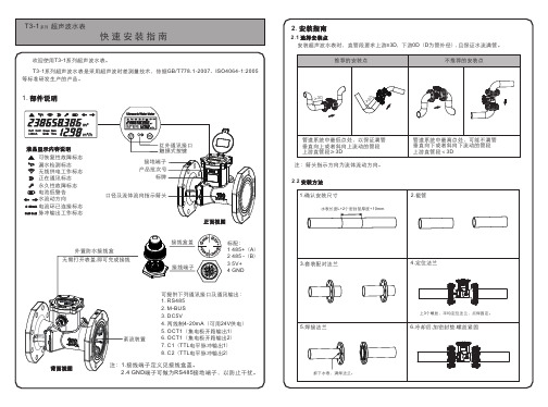
M01 显示正累计流量以及瞬时流量(水表无此窗口)
M02
主菜单 M03
显示进水、回水温度及其温差(水表无此窗口,单位只能为摄氏度) 日历,第一行显示日期,星期;第二行显示的是小时和分钟
M04 第一行显示两路信号强度,故障错误代码;第二行显示两路信号质量
M05 标定窗口
M06 定量控制器(也称为灌溉控制器)窗口
3.3 流量范围
4. 菜单简介
4.1 操作方法 T3-1系列超声波水表为触摸屏按键操作,在显示面板上两个按键分别有分别标示为“ ”和“ ”。 键盘口诀:左键“ ”上 右键“ ”下 左右键“ ”修改 右左键“ ”退出
4.2 窗口显示菜单
窗口类 窗口
显示窗口含义或者功能
M00
水表:显示净累计流量以及瞬时流量 热表:显示正累计热量以及瞬时热量
T3-1系列超声波水表设置了5类菜单选项,分别为:主菜单、辅助菜单1、辅助菜单2、定 量控制菜单、分时累积菜单。在主菜单界面下,用修改键“”可以进入任意菜单。 举例说明: 在主菜单M00时,按修改键“ ”进入月累计查询; 在主菜单M03时,按修改键“ ”进入辅助菜单1(M10~M19); 在辅助菜单1下的M19菜单,按修改键“ ”进入辅助菜单2(M20~M2A); 在主菜单M04时,按修改键“ ”进入日累计查询; 在主菜单M05时,进入启停标定状态;按修改键“ ”进入恒流标定状态; 在主菜单M06时,按修改键“ ” 进入定量控制和分时累积菜单(M30~M3C);
5. 其它
关于T3-1系列超声波水表的详细操作说明请参看《T3-1系列超声波水表使用说明书》。 您将了解到:
显示窗口详解 怎样修改计量单位? 怎样修改累积量的小数点位置? 怎样重新设定年月日时分秒星期几? 怎样确认水表是否工作完全正常? 怎样使用内置的定量控制器? 怎样修改通讯地址? 怎样修改分时累积器的时间点? 怎样修改红外通讯速率? 怎样修改RS485/M-bus通讯速率? ……
TDS-100W水表技术说明书976

TDS-100W 型系列超声波超低功耗工业水表/流量计是在目前已经在国内得到了广泛使用的 TDS-100 系列外绑式及插入式超声波流量计的基础上,采用美国德州仪器公司的超低功耗 16 位 MSP430 系列单片机为中心处理单元而研制的新一代管段式超声波流量计。在软件上我们移植了大 部分成熟的我公司外绑式流量计的主要有关流量原始数据采集、运算、流量修正等源程序;硬件上 则主要选用了世界上比较著名的半导体生产商生产的最新的低功耗集成电路;
本说明书适合 9.74 版本以上的产品,厂家保留随时更改说明书内容的权利。 王京先修改于 2008/2/27
TDS-100W 型系列超声波超低功耗工业水表/流量计
使用技术说明书
一 引言
TDS-100W 型系列超声波超低功耗工业水表/流量计是一种替代常规水表具有长寿命高可靠 高精度的全部采用工业级电子元器件制造而成的全电子工业用水表/流量计。无任何活动部件。用 户一般情况下不需要设置参数,就可像普通水表一样使用。
超声波传感器采用了已经成熟使用了三年多的我公司拥有的陶瓷传感器技术。该种技术使用陶 瓷作为压电陶瓷片的耦合片,使用焊接工艺,其特点是长期耐高温、稳定好、结实可靠。万年牢靠 不会损坏。
水表管段采用了全部铸造工艺制造,绝无开焊泄漏之虑。采用铸造工艺生产的超声波水表另一 个显著的优点是机械尺寸一致性好,其特点是超声波流量计的流量系数一致性非常好,尚没标定的 流量计就可以达到很好的绝对精度。在生产过程中,可以大大减少标定的工作量,大大提高生产效 率,便于大批量低成本生产制造。
超声波水表使用说明
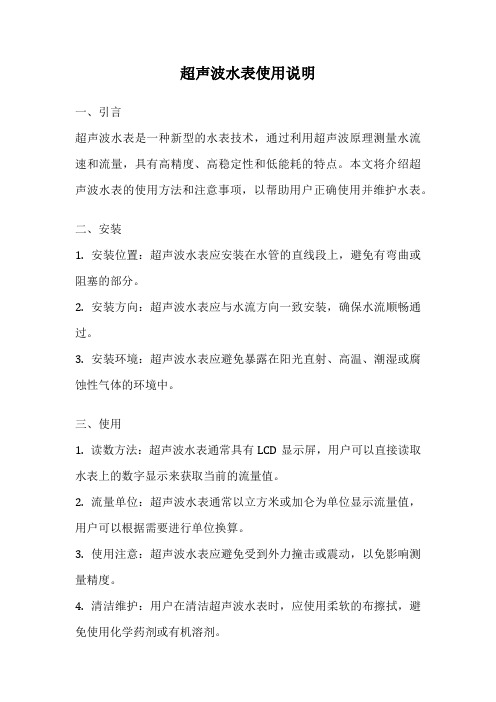
超声波水表使用说明一、引言超声波水表是一种新型的水表技术,通过利用超声波原理测量水流速和流量,具有高精度、高稳定性和低能耗的特点。
本文将介绍超声波水表的使用方法和注意事项,以帮助用户正确使用并维护水表。
二、安装1. 安装位置:超声波水表应安装在水管的直线段上,避免有弯曲或阻塞的部分。
2. 安装方向:超声波水表应与水流方向一致安装,确保水流顺畅通过。
3. 安装环境:超声波水表应避免暴露在阳光直射、高温、潮湿或腐蚀性气体的环境中。
三、使用1. 读数方法:超声波水表通常具有LCD显示屏,用户可以直接读取水表上的数字显示来获取当前的流量值。
2. 流量单位:超声波水表通常以立方米或加仑为单位显示流量值,用户可以根据需要进行单位换算。
3. 使用注意:超声波水表应避免受到外力撞击或震动,以免影响测量精度。
4. 清洁维护:用户在清洁超声波水表时,应使用柔软的布擦拭,避免使用化学药剂或有机溶剂。
四、故障排除1. 无显示:如果超声波水表无法正常显示数字,用户应首先检查电池是否正常,如果电池电量不足,应及时更换。
2. 测量不准确:如果超声波水表的测量结果与实际情况不符,用户应检查水表安装是否正确,是否有漏水或堵塞的情况。
3. 其他故障:如果超声波水表出现其他故障,用户应联系专业人员进行维修或更换。
五、注意事项1. 避免冻结:超声波水表应避免暴露在极寒的环境中,以免冻结导致损坏。
2. 定期检查:用户应定期检查超声波水表的电池电量和测量精度,以确保其正常运行。
3. 防雷措施:用户应在雷雨天气时采取防雷措施,避免超声波水表受到雷击而损坏。
4. 防水措施:超声波水表通常具有防水功能,但用户仍应避免将水直接喷洒到水表上。
六、结语通过本文的介绍,相信读者已经对超声波水表的使用方法和注意事项有了初步的了解。
正确使用和维护超声波水表,不仅可以提高测量的准确性,还可以延长水表的使用寿命。
希望本文对用户能够有所帮助,谢谢阅读!。
SC系列超声波水表DN15-DN40安装使用说明书

2019F154-37SC系列超声波水表DN15-DN40 安装使用说明书重要提示在安装前请仔细阅读本说明书,本说明书主要针对受过培训的专业人员,因此不包含基本安装步骤。
产品型号和外观如有变更,请以现场实物为准。
在不影响产品功能说明的情况下,本说明书同样适用。
如需了解详细变更情况,请与本公司联系。
本说明书版权归威海市天罡仪表股份有限公司所有,本公司对此说明书保留最终解释权。
请严格按照本说明书进行操作,以免给您的相关权益造成损失。
本产品为精密测量仪器,在出厂前经过严格检定,请由专业人员进行操作;如果本产品无法正常操作或需要维修,请联系我公司或经我公司正式授权的经销商;本产品是精密测量仪器,请勿将其摔落或使其受到撞击。
无特殊说明出厂产品参数为默认值,如有特殊要求请在订购时说明。
品质保障:设计、生产执行符合中华人民共和国国家标准GB/T 778.1-2018~GB/T 778.5-2018《饮用冷水水表和热水水表》、CJ/T434-2013《超声波水表》、CJ266-2008《饮用水冷水水表安全规则》;出厂检定依据中华人民共和国国家计量检定规程JJG162-2019《饮用冷水水表检定规程》;中华人民共和国计量器具型式批准证书2019F154-37;质量标准体系GB/T 19001-2016 / ISO9001:2015标准;环境管理体系GB/T 24001-2016 / ISO14001:2015标准;测量管理体系GB/T 19022-2003 / ISO10012:2003标准。
目录1 产品介绍 (1)1.1产品特点 (1)1.2技术参数与特性 (1)1.2.1概况 (1)1.2.2流量参数 (2)1.2.3产品尺寸 (2)1.2.4标识说明 (3)2液晶显示 (4)2.1液晶显示界面 (4)2.2故障报警显示 (4)2.3高精菜单显示 (5)3典型安装及维护指南 (6)3.1典型安装示意图 (6)3.2安装注意事项 (6)3.3几种常见的错误安装方式 (6)3.4安装步骤 (8)4产品有害物质含量状态说明 (9)5保修承诺 (9)1 产品介绍1.1产品特点低始动流量;任意角度安装;超声波信号质量检测;水温检测,低温报警;符合饮用水标准要求;磁性按键,整机IP68设计;无活动部件,无磨损,可长期稳定运行;兼容GB/T 26831、CJ/T 188及Modbus RTU 等通讯协议。
XCT-2000W新版说明书

正积量瞬时量 负积量 流速 总时间 时 间 日 期 状态本说明书适应于9.36以上版本的XCT-2000W 型超声波水表引 言XCT-2000W 系列超声波水表/流量计是一种根据欧盟EN1434标准、采用超声波时差原理进行流量测量而设计的仪表,无任何活动的机械部件,因此无磨损,具有长期测量精度不发生变化并且运行稳定可靠等特点。
质量已达到国外进口同类产品水平。
◆ 显示器和按键* 用于显示数值量。
* 符号表示超声波信号强度。
* 符号表示超声波信号质量(Q 值)。
* 符号转动表示流量不为零。
* 符号 表示存在需要修理的故障。
* 符号表示流体流动方向。
* 符号表示流量为零或未达到额定灵敏度。
* 符号表示电池电量,剩一格时表示电池电量已消耗2/3。
不显示时,必须立即更换电池。
* 符号表示瞬时流量(立方米/每小时)* 符号表示瞬时热量(吉焦耳/每小时) 热量表使用,水表无意义。
* 符号表示累积热量(千瓦时) 热量表使用,水表无意义。
* 符号表示供、回水温度差 热量表使用,水表无意义。
*分别指向面板上的汉字用于指明目前显示量。
按键有两套,一套为干簧管,不需打开机壳使用磁棒在机壳外部操作。
另外一套使用轻触按键,在机壳内部。
两套按键两两并联,分别称为“显示键” 和 “修改键”。
磁性“显示键”位于面板右下方标志处。
“修改键”位于面板左上方,并无标志。
◆用户菜单(也称为主菜单)XCT-2000W型超声波水表/流量计的显示是采用分层结构的,由用户菜单、服务菜单、设置菜单构成。
显示器上经常显示的一般是用户菜单内容。
每次轻轻按一下显示键会循环显示以下内容:用户菜单显示内容(不同型号的水表/流量计会有少许的变化)说明:1.前面的N个菜单具有自动循环显示功能,N的数目在服务菜单P0中确定,显示间隔时间在服务菜单P1中确定。
查看不在循环圈内的菜单,使用显示键。
取值0表示不循环,取值1,表示自动回到0号菜单,显示累积量。
DATA-2811 型超声水表 安装使用说明书

DATA-2811型超声水表安装使用说明书唐山平升电子技术开发有限公司售前咨询:************地址:河北省唐山市高新技术开发区庆北道37号网址:版权声明:本使用说明书包含的所有内容均受版权法的保护,未经唐山平升电子技术开发有限公司的书面授权,任何组织和个人不得以任何形式或手段对整个说明书和部分内容进行复制和转载,并不得以任何形式传播。
商标声明:为唐山平升电子技术开发有限公司的注册商标。
本文档提及的其他所有商标或注册商标,由拥有该商标的机构所有。
注意:由于产品版本升级或其他原因,本文档内容会不定期进行更新。
除非另有约定,本文档仅作为使用指导,本文档中的所有陈述、信息和建议不构成任何明示或暗示的担保。
目录1概述 (1)1.1概述 (1)1.2特点 (1)1.3本系列产品执行的标准 (1)2技术参数 (2)2.1DATA-2811型超声水表技术参数 (2)2.2流量范围 (3)3操作说明 (4)3.1面板注 (4)3.2液晶显示 (4)3.3显示内容及操作 (5)4产品安装 (8)4.1安装前准备 (8)4.2安装及其注意事项 (10)4.3整机调试 (13)5更换电池盒 (14)6标定方法 (15)6.1依据检定规程要求流量标准装置应满足如下要求: (15)6.2超声波水表安装要求: (15)6.3检定操作 (15)6.4系数修正 (16)7故障排除 (16)附录: (18)1概述1.1概述DATA-2811型超声水表采用时差法计量原理,专为供水管道及分户计量总表设计,解决了传统水表始动流量高、压力损失大、机械磨损多的难题。
在结构上采用了部件IP68化方案,即每一个部件都达到IP68防护等级,仪表腔体即使进水也能保证长期工作。
该系列水表具有精度高、量程比宽、始动流量小,性能稳定可靠等显著特点,可广泛地用于供水管网、分户用水量总表、水资源取水监测和农田灌溉等场合,同时亦可用于多种工业现场。
1.2特点●始动流速低于0.002m/s、准确度符合1级水表精度要求,实现小流量可计,降低漏损率。
TDS-100超声波流量计说明书
§1.1 引言 (1)§1.2 工作原理 (1)§1.3 主板电气原理框图 (2)§1.4 特点 (2)§1.5 性能参数 (3)§1.6 用途 (4)二产品介绍 (5)§2.1 变送型超声波流量计/热量计 (5)§2.2 经济型超声波流量变送器 (6)§2.3 超声波流量/热量变送模块 (7)§2.4 固定分体式超声波流量计/热量计 (8)§2.5 一体管段式超声波流量计/热量计 (9)三本地显示及操作 (11)§3.1 本地段式LCD显示及操作 (11)§3.2 本地LCD显示器显示内容一览表 (12)§3.3 本地显示状态代码及故障判断 (12)四并口及串口键盘显示及操作 (14)§4.1 并口键盘 (14)§4.2 串口键盘 (14)§4.3 按键功能 (14)§4.4 窗口操作 (14)§4.5 菜单分类 (16)§4.6 菜单一览表 (16)§4.7 菜单窗口详解 (19)§4.8 菜单设置特别说明 (44)五传感器安装 (46)§5.1 开箱检查 (46)§5.2 供电电源及电缆线 (46)§5.3 安装必备条件 (46)§5.4 快速输入管道参数步骤 (48)§5.5 外缚式传感器的安装方法 (50)§5.6 插入式传感器的安装方法 (52)§5.7 管段式传感器的安装方法 (56)§5.8 用户自备外缚传感器参数及其输入 (59)§5.9 通电 (59)§5.10检查安装 (59)六热量测量 (61)§6.1概述 (61)§6.2 PT100电阻的接线 (61)§6.3有关温度测量的一些菜单说明 (61)§6.4温度测量子系统的标定 (62)§6.5有关热量测量量值的输出 (63)七故障解析 (63)九输入输出回路及其使用 (67)§9.1怎样使用4-20mA电流环输出 (67)§9.2怎样输出模拟电压信号 (68)§9.3这样使用频率信号输出 (68)§9.4怎样输出累积脉冲 (68)§9.5怎样产生输出报警信号 (68)§9.6怎样使用蜂鸣器 (69)§9.7怎样使用OCT输出 (69)§9.8怎样使用继电器输出 (70)§9.9怎样连接压力信号和液位信号(模拟输入) (70)§9.10模拟输入的校准 (70)§9.11联网时模拟输入量的读取 (71)十质量保证及服务维修支持 (72)§10.1质量保证 (72)§10.2公司服务 (72)§10.3产品升级 (72)§10.4技术咨询 (72)十一附录 (73)§11.1常用液体声速和粘度 (73)§11.2常用材料声速 (73)§11.3水中声速表(1标准大气压下) (74)一概述§1.1 引言欢迎您使用大连正工仪表设备有限公司研制生产的新一代TDS-100系列超声波流量计/超声波热量计/流量变送器。
超声波水表使用说明
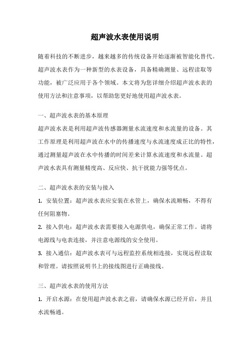
超声波水表使用说明随着科技的不断进步,越来越多的传统设备开始逐渐被智能化替代。
超声波水表作为一种新型的水表设备,具备精确测量、远程读取等功能,被广泛应用于各个领域。
本文将为您详细介绍超声波水表的使用方法和注意事项,以帮助您更好地使用超声波水表。
一、超声波水表的基本原理超声波水表是利用超声波传感器测量水流速度和水流量的设备。
其工作原理是利用超声波在水中的传播速度与水流速度成正比的特性,通过测量超声波在水中传播的时间差来计算水流速度和水流量。
超声波水表具有测量精度高、反应快、抗干扰能力强等优点。
二、超声波水表的安装与接入1. 安装位置:超声波水表应安装在水管上,确保水流顺畅,不得有任何阻塞物。
2. 接入供电:超声波水表需要接入电源供电,确保正常工作。
请将电源线与电表连接,并注意电源线的安全使用。
3. 接入通信:超声波水表可与远程监控系统相连接,实现远程读取和管理。
请按照说明书上的接线图进行正确接线。
三、超声波水表的使用方法1. 开启水源:在使用超声波水表之前,请确保水源已经开启,并且水流畅通。
2. 读取数据:超声波水表可以通过显示屏上的数据直接读取当前的水流速度和水流量。
3. 数据记录:超声波水表可以记录一定时间段内的水流速度和水流量数据,供后续分析和管理使用。
4. 故障排除:如果超声波水表出现故障或不正常的读数,请及时联系售后服务人员进行维修处理。
四、超声波水表的注意事项1. 防止冰冻:超声波水表应避免长时间暴露在低温环境中,防止结冰导致设备损坏。
2. 防止高温:超声波水表应避免长时间暴露在高温环境中,以免影响设备的正常工作。
3. 防止震动:超声波水表应避免受到强烈的震动,以免影响测量的准确性。
4. 定期维护:超声波水表需要定期进行检查和维护,确保设备的正常运行。
5. 注意安全:在维护和使用超声波水表时,请注意安全,切勿触碰设备内部的电线等部件。
总结:超声波水表作为一种新型的水表设备,具备精确测量、远程读取等功能,可以帮助用户更好地了解和管理水资源。
- 1、下载文档前请自行甄别文档内容的完整性,平台不提供额外的编辑、内容补充、找答案等附加服务。
- 2、"仅部分预览"的文档,不可在线预览部分如存在完整性等问题,可反馈申请退款(可完整预览的文档不适用该条件!)。
- 3、如文档侵犯您的权益,请联系客服反馈,我们会尽快为您处理(人工客服工作时间:9:00-18:30)。
超声波水表使用手册
感谢选用TPP-70SW系列超声波水表。
TPP-70SW系列超声波水表是基于超声波时差法原理设计而成的性能卓越的超声波测流产品。
本公司对TPP-70SW系列超声波水表拥有完整的、独立的知识产权。
使用过程中如有任何问题,欢迎来电来函。
执行标准:
生产标准:中华人民共和国国家标准GB/T778-2007《封闭满管道中水流量的测量,饮用冷水水表和热水水表》
检定标准:中华人民共和国国家计量检定规程JJG162-2009《冷水水表》重要提示:
1、使用前请详尽阅读使用手册,并妥善保管使用手册,以备查阅;
2、本产品为精密测量仪器,在安装与使用过程中尽量远离干扰源,选择合理的安装位置,并避免严重撞击、碰撞;
3、本产品出厂前均经过严格的质量检测,严禁非规范性操作或私自拆卸,否则后果自负;
4、显示图案、提示等均为窗口操作提示,并不能作为产品检定依据;
5、产品检定,请选择符合国家计量要求,正规的流量检定装置,并严格按照规范操作;
6、TPP-70SW会不定期进行升级,产品实际功能与本手册不一致时,请以实际产品为准或向厂家咨询;
7、出现错误提示时,请及时联系厂家或经销商,否则会造成流量损失。
一、产品特点:
专门用于小区分户或其它场所的小口径用水的精准计量;
最小可测流速仅为0.003m/s,真正实现滴水计量;
可实现正反流量的双向计量;
双行同屏显示,完整的提示功能,方便查询、诊断;
机身可自由近360度旋转,方便用户查阅;
小体积微功耗设计,实际使用寿命10年以上;
优良的线性度,在满量程范围内,线性一致,无须多点校正;完美的软件扩展功能,可满足不同用户的定制要求;
多种计量单位可选,满足不同国家的用户需求;
二、产品外形尺寸
公称直径(mm)L(mm)H(mm)W(mm)连接螺纹DN1511068.590.5G3/4B DN201308590.5G1B
DN2517593.590.5G1 1/4B 三、产品技术参数
特性技术参数
可测介质水及其它均质液体且充满被测管段
准确度等级优于2级
最大允许工作压力 1.6Mpa
公称通径DN15-DN25
工作环境温度:-15~55℃;湿度≤100%(RH)
温度等级T30/T50, 出厂默认为T30
上游流场敏感度等级U10
下游流场敏感度等级D5
气候和机械环境安全等级C类
电磁兼容性等级E1
数据存贮EEPROM/FLASH存储数据
数据通讯RS485/红外
工作电源 3.6V锂电池,寿命10年
防护等级 IP68
本地显示
双行显示9位累积量、4位瞬时流量及流量单位、状态提示符
四、流量范围
公称直径
(mm)
量程比
(Q3/Q1)
R
始动流量
(L/H) 最小流量 Q1 (L/H) 分界流量 Q2 (L/H) 常用流量 Q3 (m³/H ) 过载流量 Q4 (m³/H ) DN15 400 6.25 10 2.5 3.125 DN20 400 10 16 4 5 DN25
400
15.75
25.2
6.3
7.875
五、窗口操作
用磁棒触碰磁感应区即可实现显示窗口的切换、循环。
六、窗口显示
01窗口:显示净累积流量及瞬时流量。
单位可定制,常设单位为:m³和m³/h 。
36.1366 m 3 0.0000 m 3/h
02窗口:显示净累积流量和流速。
累积流量单位可定制,常设单位为:m³。
03窗口:显示累积流量(负)和瞬时流量(负)单位可定制,常设单位为m³和m³/h 。
04窗口:标定窗口
05窗口:显示时间日期。
上行显示日期,下行显示小时、分
06窗口:上行显示有效运行时间,下行显示故障时间
07窗口:上行显示传播时间,下行显示时差
08窗口:上行显示产品序列号,下行显示软件版本信息。
如需其它设定,我司可根据客户的实际需求提供定制的系统软件,从而实现多种自定义设定及显示。
七、自诊断及故障解析
标识符定义故障解析
接收信号强度识别符号。
一般情况
下,显示三个格度为最佳。
测量流量超过过载流量(Q4)
测量流量低于最小流量(Q1)
测量介质流动方向提示符
当提示仅一个格度时,请尽快更电池电量提示符
换电池,否则会造成流量丢失。
不可修复故障提示符联系厂家或经销商
频繁出现时,重点检查是否空管可修复故障提示符
或气泡过多。
排除气泡或杂质。
正在通讯标识
滴水计量或漏水标识
空管提示符
八、标定
1、检定方法遵循国家计量检定规程JJG162-2009--《冷水水表》
2、标定时请选择经过计量部门认证的、正规的流量检定装置并经专业人员规范操作;
3、本系列产品(DN15-DN25)更适于“启停法”标定;
4、本系列产品可即标即用,无附加操作,实现检定精度与实际使用精度一致。
(检定时的附加操作往往隐含着计量精度上的猫腻);
5、显示分辨率用户可自定义,出厂设定为0.1升;
6、为了更方便的显示结果,标定时可选择“04”号窗口进行检定,具体定义如下:
用磁棒下移窗口至“04”号窗口
磁棒长按,液晶左上角显示P字。
当P闪烁意味可以标定;
磁棒短按,开始标定;
磁棒再次短按,标定结束,读取数据;
磁棒再次短按,显示清零;
长按磁棒,标定完成。