ALESIS反馈抑制器DFB-224产品图片及参数说明
Belimo EV24A-RE 2-way和3-way球值驱动器说明书
EV24A-REGlobe valve actuator for 2-way and 3-way globevalves• Actuating force 2500 N• Nominal voltage AC/DC 24 V• Control Open/close, 3-point• Stroke 50 mmTechnical dataElectrical data Nominal voltage AC/DC 24 VNominal voltage frequency50/60 HzNominal voltage range AC 19.2...28.8 V / DC 21.6...28.8 VPower consumption in operation 2.5 WPower consumption in rest position0.5 WPower consumption for wire sizing 4.5 VAConnection supply / control Terminals 4 mm² (cable ø4...10 mm)Parallel operation Yes (note the performance data)Functional data Actuating force motor2500 NManual override with push-button, can be lockedStroke50 mmRunning time motor150 s / 40 mm (188 s / 50 mm)Sound power level, motor56 dB(A)Position indication Mechanical, 5...50 mm strokeSafety data Protection class IEC/EN III, Safety Extra-Low Voltage (SELV)Power source UL Class 2 SupplyDegree of protection IEC/EN IP54Degree of protection NEMA/UL NEMA 2Enclosure UL Enclosure Type 2EMC CE according to 2014/30/EUCertification IEC/EN IEC/EN 60730-1 and IEC/EN 60730-2-14UL Approval cULus according to UL60730-1A, UL60730-2-14and CAN/CSA E60730-1The UL marking on the actuator depends onthe production site, the device is UL-compliantin any caseType of action Type 1Rated impulse voltage supply / control0.8 kVPollution degree3Ambient humidity Max. 95% RH, non-condensingAmbient temperature0...50°C [32...122°F]Storage temperature-40...80°C [-40...176°F]Servicing maintenance-freeWeight Weight 3.2 kgEV24A-RE••••••Safety notesThis device has been designed for use in stationary heating, ventilation and air-conditioning systems and must not be used outside the specified field of application, especially in aircraft or in any other airborne means of transport.Outdoor application: only possible in case that no (sea) water, snow, ice, insolation or aggressive gases interfere directly with the device and that it is ensured that the ambient conditions remain within the thresholds according to the data sheet at any time.Only authorised specialists may carry out installation. All applicable legal or institutional installation regulations must be complied with during installation.The switch for changing the direction of motion and so the closing point may be adjusted only by authorised specialists. The direction of motion is critical, particularly in connection with frost protection circuits.The device may only be opened at the manufacturer's site. It does not contain any parts that can be replaced or repaired by the user.The device contains electrical and electronic components and must not be disposed of as household refuse. All locally valid regulations and requirements must be observed.Product featuresMounting on third-party valvesThe RetroFIT+ actuators for installation on a wide range of valves from various manufacturers are comprised of an actuator, universal valve neck adapter and universal valve stem adapter. Adapt the valve neck and valve stem to begin with, then attach the RetroFIT+ actuator to the valve neck adapter, connect to the valve and start up. The valve neck adapter/actuator can be rotated by 360° on the valve neck, provided the size of the installed valve permits.Mounting on Belimo valvesUse standard actuators from Belimo for mounting on Belimo globe valves.Manual overrideManual override with push-button possible (the gear train is disengaged for as long as the button is pressed or remains locked).The stroke can be adjusted by using a hexagon socket screw key (5 mm), which is inserted into the top of the actuator. The stem extends when the key is rotated clockwise.High functional reliabilityThe actuator is overload protected, requires no limit switches and automatically stops when the end stop is reached.Home positionFactory setting: Actuator stem is retracted.Setting direction of motion When actuated, the stroke direction switch changes the running direction in normal operation.Restriction 3-point controllerIt must be ensured that the pulsating 3-point controller stops when the end position is reached. If this is not possible on the system side, the multifunctional 24 V version of the actuator (..V24A-MP-..) must be used.AccessoriesElectrical accessories DescriptionType Auxiliary switch 2x SPDT add-on S2A-H Mechanical accessoriesDescriptionType Spacer ring for Sauter, stroke 50 mm ZRV-301Spacer ring for Siebe, stroke 50 mmZRV-302Spacer ring for Johnson Control, stroke 50 mm ZRV-303Washer Sauter for Sauter, stroke 50 mmZRV-304EV24A-REElectrical installationSupply from isolating transformer.Parallel connection of other actuators possible. Observe the performance data.Direction of stroke switch factory setting: Actuator stem retracted (▲).Wiring diagramsAC/DC 24 V, open/close AC/DC 24 V, 3-pointOperating controls and indicators1Direction of stroke switchSwitch over:Direction of stroke changes4Manual override buttonPress button:Gear train disengages, motor stops, manual override possibleRelease button:Gear train engages, standard mode10Manual overrideClockwise:Actuator stem extendsCounterclockwise:Actuator stem retractsEV24A-RE DimensionsFurther documentation• Installation instructions for actuators。
多功能电力仪表PD194Z-2S4 2S4D 2S4+用户手册说明书

多功能电力仪表用户手册适用型号:PD194Z-2S4/2S4D/2S4+PD194Z-2S9/2S9D/2S9+PD194Z-2S7/2S7+PD194E-2S4/2S4+/2S9/2S9+/2S7/2S7+ PD194Z-9S4/9S4+/9S9/9S9+/9S7/9S7+ PD194E-9S4/9S4+/9S9/9S9+/9S7/9S7+安全须知感谢您选择江苏斯菲尔电气股份有限公司研发的产品,为了方便您选购和安全、正确、高效的使用本产品,请仔细阅读本手册并在使用时务必注意以下几点。
注意CAUTION:◆该装置必须有专业人员进行安装与检修◆在对该装置进行任何内部或外部操作前、必须切断输入信号和电源◆始终使用合适的电压检测装置来确定仪表各部位无电压◆提供给该装置的电参数需在额定范围内下述情况会导致装置损坏或装置工作的异常:◆辅助电源电压超范围◆配电系统频率超范围◆电流或电压输入极性不正确◆带电拨通信插头◆未按要求连接端子连线本手册可以在本公司的主页上下载到最新版本,同时也提供一些相应的测试软件下载。
如果您需要电子版用户手册可以向本公司的技术服务部门索取。
目录1产品简介 (1)1.1概述 (1)1.2选型 (1)2技术规格 (4)2.1技术参数 (4)2.2测量参数 (6)3安装与接线 (7)3.1尺寸 (7)3.2安装 (8)3.3接线 (9)4操作 (12)4.1面板 (12)4.2显示 (13)4.2.1电量显示 (13)4.3设置 (17)4.3.1系统设置 (21)4.3.2信号输入设置 (22)4.3.3通信设置 (23)4.3.4继电器输出设置 (24)4.3.5模拟量输出设置 (25)5功能 (26)5.1需量记录 (26)5.2电能脉冲输出 (26)5.3开关量输入 (27)5.4继电器输出 (28)5.5模拟量输出 (29)5.6模拟量输入 (30)6通信 (31)6.1物理层 (31)6.2通信协议MODBUS-RTU (31)6.3报文指令格式 (32)6.4数据格式 (38)附录MODBUS-RTU通信寄存器信息表 (39)一次电网数据 (39)二次电网数据 (40)生产信息 (41)参数设置 (41)1产品简介1.1概述PD194系列多功能电力仪表是针对电力智能监控和电能计量需求设计,能测量三相电网中的常用电力参数,三相电压、电流、功率、功率因数、频率、电能、需量等。
埃斯顿 PXS24 电子保护模块应用指南说明书

PXS24Application NoteEaton - A new era of electronic protective devicesExample with activeActive current limitation of the PXS24The electronic protection module PXS24 switches, in contrast to conventional thermomagnetic circuit breakers, not mechanically but via a semiconductor element. This allows a more sensible response and guarantee a safe switch off in circuits with long lines and small wire cross sections. The PXS24 also has anactive current limiter, which protects the upstream power supply in case of an overload or short-circuit. This ensures selectivity, since only the concerned circuit is switched off and makes the troubleshooting more easy. Once the current reaches 1.3 times I N , PXS24 reduce the current to 1.25 times I N , limit it to that level and switch-off according to the switch-off time. This protects the feeding power supply. The guaranteed non-tripping value of the PXS24 is 1.1 times the rated current. In comparison, at a conven-tional circuit breaker, the occurring fault current can exceed the rated current up to 20 times, depending on the characteristics. This leads to a higher stress factor and in worst case to a break-down of the upstream power supply.Based on the defi ned switch-off times PXS24 is also able to hand-le system caused load peaks which normally leads to a nuisance tripping. Another signifi cant advantage is to guarantee a reliable operation of the power supply because the current limitation al-lows an easy dimension of the system. 100% of the load carrying capacity can be used without the risk to generate a unwanted shut down of the system.Today’s power supplies can have an integrated …Power Boost“, which allows that the rated current can be exceed by a certain factor. Thus, e.g. The Eaton PSG power supplies are capable of holding 150% of the rated power for 5s. In case of a short circuit or extreme overload, the current can quickly reach 10 times the rated current and, if not limited, the power supply switch off (2).If you have an electric overcurrent protection with active current limitation (PXS24), the current can increase to a maximum of 1.3 times the value of the rated current of the device in case of a short circuit and the power supply unit is protected (1).This also results in easier fault fi nding, since it is immediately apparent in which path there is a malfunction.Note for UL applications: The PXS solid state overcurrent protec-tor has been tested in accordance to UL 508 and CSA 22.2 No. 14 for DC general use. Temperature, overload and endurance, dielectric and breakdown of component tests were conducted. Calibration and overloaded operation tests were conducted in accordance with UL 2367.Time / Current table Current I N Shutdown Active current limitation 2A 470 ms 1.25 x I N 4A 280 ms 1.25 x I N 6A 170 ms 1.25 x I N 8A 110 ms 1.25 x I N 10A 90 ms 1.25 x I N 13A 80 ms 1.25 x I N 16A70 ms1.25 x I NExample without active(1) (2)Here you can see the much more sensitive trip range of the electronic protection unit (e2 - e16) compared to the conventio-nal, thermomagnetic CB (FAZ B2 - B16 or FAZ Z2 - Z20). Those switching devices whose trip ranges are within the trip limits of the power supply (green shaded area) also ensure that in case of a short circuit or an extreme overload the power supply does not switch off.Overload behaviorCompared to short-circuit tripping, the conventional circuit brea-ker reacts much more slower in the event of a thermal overload, as a result of which the upstream power supply can also be overstressed. On the other hand, the PXS24 does not differen-tiate between short circuit and overload and thus offers a more precise shutdown behavior.The PXS24 processes the overload just like a short circuit. Once the current reaches 1.3 times I N , PXS24 reduce the current to 1.25 times I N , limit it to that level and switch-off according to the switch-off time:The following values apply to thermal overload:Conventional CB (FAZ)IEC/EN 60947-2IEC/EN 60898-1Fixed non-tripping current 1.05*I N > 1h 1.13*I N > 1h Fixed tripping current1.30*I N < 1h1.45*I N < 1hComparison of the DC short-circuit release with:- Conventional thermomagnetic circuit breakers (FAZ)- Electronic protection module without active current limitation- Electronic protection module with active current limitation (PXS24)Time / Current table Current I N Shutdown Active current limitation 2A 470 ms 1.25 x I N 4A 280 ms 1.25 x I N 6A 170 ms 1.25 x I N 8A 110 ms 1.25 x I N 10A 90 ms 1.25 x I N 13A 80 ms 1.25 x I N 16A70 ms1.25 x I N20 A Power SupplyEaton PSGPowerboost max. 5sWhen using an electronic protection module without current limiter, a short circuit or extreme overload will cause a sudden shutdown of the power supply unit.The maximum upper limit of the current to be reached in the event of a short circuit in the PXS24 is 1.3 x I for all rated currents (2 - 16 A). All values are within the control limits of the power supply and 100% selectivity can be used.Tripping areas of the FAZ circuit breakers with Z-characteristic (2,8 - 4,2 x I ) in the event of a short circuit (magnetic release).Tripping areas of the FAZ circuit breakers with B-characteristic (4.2 - 7,1 x I ) in the event of a short circuit (magnetic release).Current I [A]V o l t a g e U = 24 V D C9010238083516Follow us on social media to get the latest product and support information.Eaton is a registered trademark.All other trademarks are property Eaton Industries (Austria) GmbH Scheydgasse 421210 Vienna AustriaEatonEMEA Headquarters Route de la Longeraie 71110 Morges, Switzerland Eaton.eu© 2018 EatonAll Rights Reserved Printed in AustriaPublication No. BR019012EN Article number 195234-MK December 2018Changes to the products, to the information contained in thisdocument, and to prices are reserved; so are errors and omissions.Only order confirmations and technical documentation by Eaton is binding. Photos and pictures also do not warrant a specific layout or functionality. Their use in whatever form is subject to prior approval by Eaton. The same applies to Trademarks (especially Eaton, Moeller,and Cutler-Hammer). The Terms and Conditions of Eaton apply, as referenced on Eaton Internet pages and Eaton order confirmations.Eaton is a power management company with 2017 sales of $20.4 billion. We provide energy-effi cient solutions that help our customers effectively manage electrical, hydraulic and mechanical power more effi ciently, safely and sustainably. Eaton is dedicated to improving the quality of life and the environment through the use of power managementtechnologies and services. Eaton has approximately 96,000 employees and sells products to customers in more than 175 countries. For more information, visit .。
百灵达DSP1124P返馈抑制器使用说明书
FEEDBACK DESTROYER PRO24-Bit Dual Engine Digital Feedback Destroyer / Parametric EQ Model DSP1124P产品特性:高性能两通道数字反馈抑制器带参量均衡 24比特高速DSP芯片。
24比特数/模,模/数转换器;64/128倍超采样带来宽阔净空高度。
自动/智能地寻找并抑制声反馈的发生,每通道可以设置12路抑制频率。
24个可编程参量滤波器,可手动设置或通过MIDI接口。
“SET-AND-FORGET”默认设置可以达到简单而迅速的抑制效果。
“SINGLE SHOOT”可自动寻找抑制声反馈,并锁定滤波电路直到手动解除。
自动模式可以保持对信号的监控,并自动调整滤波频率。
手动模式允许最大2X12路参量滤波线路,频率、带宽和增益均可调节。
每个滤波器都可在“SINGLE SHOOT,自动和手动”三种模式中选择。
提供免费的远程控制软件,可在下载.两个数字处理引擎可独立或配合使用(分左右声道)。
镀金平衡插座(XTR和1/4 TRS)减少信号损耗。
内部24比特处理器,专业级64K采样率。
MIDI兼容,用户设置可储存和随时调出。
8段式LED显示使调节更方便,更准确。
可软件升级,保护用户投资。
高品质零件和坚固的机壳结构保证本产品经久耐用。
专为专业场合所设计的内部电源供应线路通过ISO9000系列认证1. 产品介绍非常感谢您对BEHRINGER产品的信任。
DSP1124P反馈抑制器是一种在专业扩声领域非常有用的设备,她可以使您在使用过程中专注于您工作的重点—音乐。
DSP1124P不仅是一台反馈抑制器,更提供了大量附带功能。
24个滤波器均可独立调节所有参数,并可自动检测抑制反馈;提供专业内部处理线路,还可作为舞台和录音间的高端均衡器;DSP1124P还可应用于MIDI系统;另外,开放的系统结构设计还可以让你升级系统软件。
简而言之,DSP1124P是你可以长期信赖的伙伴。
百灵达反馈抑制器FBQ2496

1. 引论
深圳市成海音响灯光设备有限公司
3
FEEDBACK DESTROYER PRO FBQ2496
3. 操作元件和接口
3.1 正面
G RESET
短时按 RESET 复原键后、所有自动放置的滤波器均 被删除。长时按键后、单发滤波器也被删除。 在 PEQ 模式中、短时按键可删除选出的滤波器。长时 按键可一次删除全部的参数滤波器。
H 状态显示
FBQ2496 一共有 40 个滤波器、即每个通道有 20 个 滤波器。你可通过状态显示方便地监视这些滤波器。 一个恒定发亮的发光二极管表示:
已放置了一个滤波器:它已抑制一个反馈。或: 一个滤波器处于参数均衡器模式 (PEQ)、这时 必须已设置了一个大于或小于 0 dB 的放大 (Gain)。 一个定期闪烁的发光二极管表示 PEQ 模式中选用的 滤波器。
E FREEZE
如果 FBQ249结键将其保存。所有的单发和自动滤波器均保持其 设置、直到再次按下 FREEZE 键。
F FILTER LIFT
所谓的 “Filter Lifting Time (滤波器升高时间) ” 指 的是一个已调节好的自动滤波器在复原其数值之前 允 许 不 起 作 用 的 时 间 长 度。这 个 时 间 可 在 短 时 按 下 FILTER LIFT 键后在旋转钮上调节。可调节为以下时 间长度:0 分钟、1 分钟、5 分钟、10 分钟、30 分钟、 60 分钟。
I 发光二极管显示
三位数数值的显示表示的是你改变的那个参数的绝对 值。有关如何调节各个参数请参阅第 4 章。
Hz 或 kHz 在改变一个滤波器的中心频率时发亮。 min 显示在设置了滤波器的升高时间时发亮。 1/60 发光二极管在滤波品质设置为小于 0.1 时发 亮。随后可设置为数值 1/60、2/60、3/60、4/60 和 5/60 (6/60 = 0.1)。 如果设置了滤波器的下降或抬升、则 dB 发光二极 管发亮。 MIDI 显示在设备接收 MIDI 数据时短时亮一下。
论-DFB2212数字反馈抑制器的应用
容 易 被设 备识 别 出来 。即使 是 加 了混 响处 理 的啸 叫
信号 , 设 备也 不 会 认 错 。这 也 是 因 为 啸 叫信 号 的频
谱 根 本 就是 一点 变 化 也 没 有 , 我 们 听 着 它 实 在 太 难
听了。
影 响反馈 抑 制 器 效 果 的另 一 个 方 面 是 : 陷 波 的 深 度 和 宽度 。通 常 我 们 希 望 陷 波 的 深度 浅 一 点 、 窄
一
点, 对 原信 号 的破 坏 作 用 就 会 轻 一 些 。现 在 的反
馈 抑 制器 抑 制器 陷波 深 度 都 设 置 为 多 阶 陷 波 方 式 , 及 出 现 啸 叫频 率 后 , 设备 现 予 以浅 度 的陷 波处 理 , 再
次 出 现 啸 叫后 , 才加 深 陷 波 的深度 。 综合 以上情 况 , 我们 可 以得 出如下 结论 : 反馈 抑 制 器 若要 得 到较 好 的处 理 效 果 , 要 求 其 具 有 足 够 快 的扫 描速 度 , 较 窄 的陷 波宽 度 和更 多 的陷 波器 数 量 。
谐 音 或颤 音 , 它 与 啸叫 信号 之 间 的差 别十 分 明显 , 很
确认 键 , 用 于确 认 修改 的参数 。持 续 按 2秒 , 反 馈 抑 制器即处于工作状态 ; ⑩表 示 E S C取 消 键 , 用 于 取 消 修改 内容 。持续 按 2秒 , 反 馈 抑 制 器 将 处 于 旁通 状态 ; ⑩ 表 示 TE R MI NAT 0R 反 馈 抑 制 模 式 开 关 , 按下 后 自动 进 入工 作状 态 , 持续 按 2秒后 , 内部 滤 波 器将 回到初 始 状态 ; ⑩ 表 示 UTI L功 能选 择 菜 单 , 这 里 可选 择 : 预置 参 数载 人 ( L OA D P R E S E T) , 参 数储 存( S T OR E P R E S E T) , 反馈 抑 制参 数 设置 ( TE R — MI NAT 0R S E TUP) 、 滤波器参 数编辑 ( F I L TE R E D I T ) 、 滤波器参 数重 置 ( F I L T E R R E S E T) 、 MI D I
dbx_afs224_说明书

双通道高级反馈抑制器用户手册dbx 专业产品AFS 224 双通道高级反馈抑制器用户手册目录AFS 224 的特性-----------------------------------------------------------------------------------------------2服务联系信息--------------------------------------------------------------------------------------------------3 保证--------------------------------------------------------------------------------------------------------------3 安装建议--------------------------------------------------------------------------------------------------------4 基本连接--------------------------------------------------------------------------------------------------------4 后面板连接-----------------------------------------------------------------------------------------------------5 前面板连接-----------------------------------------------------------------------------------------------------5 用户设置--------------------------------------------------------------------------------------------------------6 应用-------------------------------------------------------------------------------------------------------------10 方框图----------------------------------------------------------------------------------------------------------14 技术规格-------------------------------------------------------------------------------------------------------15安恒利(国际)有限公司2004.4序祝贺您选择dbx AFS 224 专业产品。
百灵达反馈抑制器FBQ2496
N BANDWIDTH
用 BANDWIDTH 带宽键你可确定选出的参数滤波器 的频带宽度 (Q 因数 / 品质)。可调节的滤波品质包 括从 1/60 个八度音至 10 个八度音的范围。为此 FBQ2496 必须位于 PEQ 模式中 (PEQ 键上的发光 二极管发亮)。
FBQ2496 是市场上最快速的 (>0.2 秒)和同时唯一的 96 kHz 反馈抑制器。它具备超速和智能的反馈识别算法、 能够自动测定每条通道最多达 20 个的反馈频率的位置、 并通过极窄的陷波滤波器来抑制这些反馈频率、而有用信 号几乎不受影响。
“Set-and-Forget”(设定既忘)功能和紧急键功能确保了特 别简单和立即生效的反馈抑制。在自动模式中、混音被持 续监视、滤波器调节自动调整。而在手动模式中、可放置 最多达 40 个的全参数滤波器、其频率、频带宽度、抬高 / 下降可调节。开放的 MIDI 结构使今后能够进行软件的更新 升级、并方便了同数字式设备的交流。在现场使用时、你 可通过 不同的运 行方式来灵 活配合不同 的情形。此外、 FBQ2496 作为有创新力的声音制作工具也适合在录音室 中使用。
深圳市成海音响灯光设备有限公司
4
3. 操作元件和接口
FEEDBACK DESTROYER PRO FBQ2496
K PEQ
在 长时按 了 PEQ 键后 (PEQ 键上的发 光二极管 闪烁)、可用旋转钮调节参数滤波器的数量。数量始 终从滤波器 20 开始、可逐步增加至滤波器 1 (参见 图 4.2)。同时显示设置的单发滤波器。如 果 只 是 短 时按 PEQ 键 (PEQ 键上的发光二极管发亮)、可用 旋转钮选择每个滤波器。这时所选出的滤波器的编号 在显示器中显示、该滤波器发光二极管闪烁。现在可 显示放大、频带宽度和中心频率这几个参数。
BF24-T-ST火灾和烟雾遮挡器说明书
Spring-return actuator, combined with thermoelectric tripping device (72°C), for fire and smoke dampers 90° in ventilation and air-conditioning systems, with connection plugs for simple integration in control and monitoring systems or bus networks via communication and power supply units• Nominal torque 18 Nm / 12 Nm • Nominal voltage AC/DC 24 V • Control open-close• Damper rotation form fit 12 mm(10 mm with enclosed adapter)Technical dataElectrical dataNominal voltageAC/DC 24 V Nominal voltage frequency 50/60 HzNominal voltage rangeAC 19.2 V ... 28.8 V / DC 21.6 V ... 28.8 V Power consumption in operation 7 W Power consumption at rest2 W Power consumption for wire sizing10 VAPower consumption for wire sizing note Imax 8.3 A @ 5 ms Auxiliary switch2 x SPDTSwitching capacity auxiliary switch Contact gold-plated silver: 1 mA … 3 (0.5) A, DC 5 V … AC 250 V (II Totally insulated)Switching points auxiliary switch 5° / 80°Connection supplyCable 1 m, 2 x 0.75 mm² (halogen-free)Connection auxiliary switch Cable 1 m, 6 x 0.75 mm² (halogen-free)Connection plugSupply: 3-pole plug, suitable for communication and power supply units (see "Accessories")Auxiliary switch: 6-pole plug, suitable for communication and power supply units (see “Accessories”)Cable length thermoelectric tripping device1 mFunctional dataTorque motorMin. 18 Nm Torque spring-returnMin. 12 NmDirection of rotation motor Can be selected by mounting L / RAngle of rotation Max. 95° (incl. 5° initial spring tension)Running time motor<120 s / 90°Running time spring-return 16 s (tamb = 20°C)Sound power level motor max.45 dB (A)Sound power level spring-return max.63 dB (A)Damper rotation Form fit 12 mm (10 mm with enclosed adapter)Position indication Mechanically, with pointer Service lifeMin. 60,000 safety positionsSafetyResponse temperature thermal fuse Tf1: Duct outside temperature 72°CTf2 and Tf3: Duct inside temperature 72°C Protection class IEC/EN III Safety extra-low voltage Degree of protection IEC/EN IP54 in all mounting positions EMCCE according to 2014/30/EU Low-voltage directive CE according to 2014/35/EUCertification IEC/ENCertified according to IEC/EN 60730-1 and IEC/EN 60730-2-14Mode of operationType 1.AA.B Rated impulse voltage supply / control 0.8 kV Control pollution degree3Ambient temperature normal duty -30°C ... 50°CAmbient temperature safety dutyThe safety position will be attained up to max. 75°CP ro du ct nol on ge r a v a i l ab l eSafetyNon-operating temperature -40°C ... 50°CAmbient humidity 95% r.h., non-condensing Maintenance Maintenance-free WeightWeight approx.2.8 kgSafety notes!Product featuresMode of operationThe actuator moves the damper to the operating position at the same time astensioning the return spring. The damper is turned back to the safety position by spring energy when the supply voltage is interrupted.Thermoelectric tripping deviceIf the ambient temperature of 72°C is exceeded, the thermal fuse Tf1 responds.If the duct inside temperature of 72°C is exceeded, the exchangeable thermal fuse Tf2/Tf3 will respond.When the thermal fuses Tf1, Tf2 or Tf3 respond, the supply voltage is interrupted permanently and irreversibly.The LED is lit when– there is a supply voltage,– the temperature fuses are OK and – the test switch is not pressed.The function of the thermal fuse and the test button is only warranted if the actuator is connected to the power supply and has reached its operating position (LED on).SignallingTwo microswitches with fixed settings are installed in the actuator for indicating the damper end positions.The position of the damper blade can be read off on a mechanical position indicator.Manual operationWithout power supply, the damper can be operated manually and fixed in any required position. It can be unlocked manually or automatically by applying the supply voltage.Standards / RegulationsThe design of the actuator is based on the specific requirements from the European standards:- EN 15650 Ventilation for buildings – Fire dampers- EN 1366-2 Fire resistance tests on service installations (Part 2: Fire dampers)- EN 13501-3 Fire classification of construction products and building elements(Part 3: Classification using data from fire resistance tests on products and elements used in building service installations: fire resisting ducts and fire dampers)Recommendation for applicationRegular operational checks (open-close control of the fire damper) enhance the safety of people, animals, property and the environment. Unless other requirements are stipulated – e. g. in the damper manufacturer's operating instructions – Belimo recommends the performance of monthly operational checks. Fire damper actuators from Belimo are designed in accordance with service life specifications contained in the technical data sheet for regular operational checks. Notes for regular operational checks can be found in the European Product Standard for Fire Dampers (EN 15650) under «Maintenance information».Spring-return actuator 90°, AC/DC 24 V, 18 Nm / 12 Nm, with BAE.., with plugTechnical data• The actuator is adapted and installed on the fire and smoke damper by the damper manufacturer. For this reason, the actuator is only supplied directly to safety damper manufacturers. The manufacturer then bears full responsibility for the proper functioning of the damper.• The two switches integrated in the actuator are to be operated either on powersupply voltage or at safety extra-low voltage. The combination power supply voltage/safety extra-low voltage is not permitted.• The device may only be opened at the manufacturer‘s site. It does not contain any parts that can be replaced or repaired by the user.• The device contains electrical and electronic components and is not allowed to be disposed of as household refuse. All locally valid regulations and requirements must be observed.• The device must not be used outside the specified field of application, especially not in aircraft or in any other airborne means of transport.P ro du ct nol on ge r a v a i l ab l eDescriptionData sheet name Electrical accessoriesAuxiliary switch 2 x SPDTSN2-C7Cable set with plug, L = 0.5 m for communication and power supply unit ZST-BS Blanking cover for BAE (without thermal fuse for duct inside temperature)ZBAE0Spare tripping element for BAE, duct inside temperature = 72 °C, sensor length = 65 mmZBAE72Spare tripping element for BAE, duct inside temperature = 95 °C, sensor length = 65 mmZBAE95Communication and power supply unit for integration in SBS-Control networksBKN230-24Communication and power supply unit for integration in SBS-Control and MP bus networksBKN230-24-C-MP Mechanical accessoriesAdapter with clamp for round spindle 10...20 mm / square 10…16 mm for BFZK-BF Adapter for form fit 12 mm with round spindle 18 mm, L = 33 mm for BF ZA18-BF Adapter 12/8 mm for BF.. and BLF..ZA8-BF Adapter 12/11 mm for BF.. and BLF..ZA11-BF Bracket for auxiliary switch (SN2-C7) for BF, BRZSN-BFElectrical installationWiring diagrams AC/DC 24, open-closeConnection by means of plug at communication and power supply units:Application examples for the integration into monitoring and control systems or into bus networks can be in thedocumentation of the connected communication and power supply unit (see "Accessories").Spring-return actuator 90°, AC/DC 24 V, 18 Nm / 12 Nm, with BAE.., with plugAccessoriesProduct featuresConnectingThe actuator is fitted with plugs. This means that it can be integrated via a communication and power supply unit (see "Accessories") in the control andmonitoring systems (e.g. SBS control) or in bus networks (e.g. MP bus solutions).nol on ge r a v a i l ab l eDimensional drawingsSpring-return actuator 90°, AC/DC 24 V, 18 Nm / 12 Nm, with BAE.., with plugDimensions [mm]P ro du ct nol on g。
SABINE FBX-2420反馈抑制器
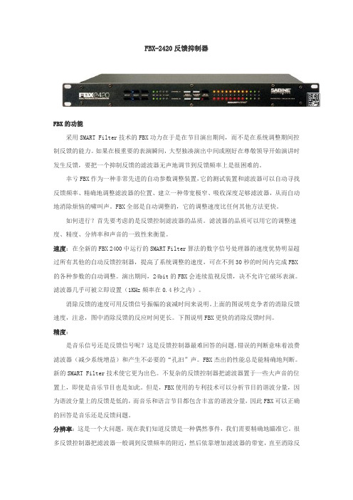
FBX-2420反馈抑制器FBX的功能采用SMART Filter技术的FBX功力在于是在节目演出期间,而不是在系统调整期间控制反馈的能力。
如果在极重要的表演瞬间,大型独凑演出中间或刚好在尊敬领导开始演讲时发生反馈,要把一个抑制反馈的滤波器无声地调节到反馈频率上是很困难的。
幸亏FBX作为一种非常先进的自动参数调整装置,它的测试装置和滤波器可以自动寻找反馈频率、精确地调整滤波器的位置、建立一种带宽极窄、吸收深度足够滤波器,从而自动地消除烦恼的啸叫声。
FBX全部是自动调整的,它的调整速度比任何其他方法更快。
如何进行?首先要考虑的是反馈控制滤波器的品质。
滤波器的品质可以用它的调整速度、精度、分辨率和声音的一致性来衡量。
速度:在全新的FBX 2400中运行的SMART Filter算法的数字信号处理器的速度优势明显超过所有其他的自动反馈控制器,提高了系统调整的速度,可在不到30秒的时间内完成FBX 的各种参数的自动调整。
演出期间,24bit的FBX会连续监视反馈,决不允许它破坏表演。
滤波器几乎可被立即设置(1KHz频率在0.4秒之内)。
消除反馈的速度可用反馈信号振幅的衰减时间来说明。
上面的图说明竞争者的消除反馈速度,注意,图中消除反馈的反应时间更长。
下图说明FBX更快的消除反馈时间。
精度:是音乐信号还是反馈信号呢?这是反馈控制器最难回答的问题。
错误的判断意味着浪费滤波器(减少系统增益)和产生不必要的“孔汩”声。
FBX杰出的性能总是能精确地判断。
新的SMART Filter技术使它更为出色。
不复杂的反馈控制器把滤波器置于一些大声音的位置上,即使是音乐节目也是如此。
但是,FBX使用的专利技术可以分析节目的谐波分量,因为谐波分量上的反馈是低的,而音乐和语言节目都包含丰富的谐波分量,因此FBX可以正确的回答是音乐还是反馈问题。
分辨率:这是一个大问题,现在我们知道反馈是一种偶然事件,我们需要精确地瞄准它。
很多反馈控制器把滤波器一般调到反馈频率的附近,然后依靠增加滤波器的带宽,直至消除反馈。
4端口FXS语音接口模块产品手册

第4页,共9页
B 产品手册
产品型号:TY4S-48B
联系人付先生:13871048528
—————————————————————————————————————————
DOUT: IO = –40 mA VDD – 0.8
SDITHRU:
输出低电平 Low Level Output Voltage
Vrms
-
Fr
-
f = 25 Hz
-1
-
Tdbr
-
Rdbr
-
典型值 (type)
48 20 -
160
-
-
600 Cplx680 Cplx560 60 25 0 -3.5
最大值 (max)
4 45 10
-
-
20
20
-
1 600 -
单位 (unit)
V
V mA %
Ω
kΩ
%
%
Ω
V Hz % ms dbr dbr
武汉市中光同友通信有限公司
第3页,共9页
TY4S-48B 产品手册
产品型号:TY4S-48B
联系人付先生:13871048528
—————————————————————————————————————————
2.1 电路结构框图 (FXS System Architecture)
图 1 FXS 结构框图
武汉市中光同友通信有限公司
第2页,共9页
TY4S-48B 产品手册
产品型号:TY4S-48B
联系人付先生:13871048528
—————————————————————————————————————————
WEN 电子炸锅 EEG-241、242、243、244 产品说明书
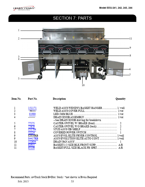
Item No. Part No. Description Quantity1151171WELD ASSY-WENDYS BASKET HANGER ......................1/ well 2 76555 WELD ASSY-COVER FULL ................................................. 1/vat 3 81980 LED-5MM BLUE ................................................................... 1/vat 4 -------- DRAIN KNOB ASSEMBLY................................................... 1/vat--See DRAIN KNOB drawing for breakdown5 77575 CASTER-SWIVEL W/ BRAKE (front) .................................. 26 77679 CASTER-SWIVEL W/O BRAKE (back) ............................... 27 151704 STUD ASSY-JIB SHELF ........................................................ 18 52224 COVERED POWER SWITCH ............................................... 19 82016RB ASSY-EVOL/ELITE FRYER CONTROL ..............................1/well 9 84417RB ASSY-EVOLUTION ELITE AUTO CONT ...........................1/well 10 152634 DRAIN PAN ASSY ................................................................. 1 11 81915 BASKET-1/2 SIZE BLK FRONT SUPP ................................. A/R 1185136BASKET-FULL SIZE BLACK FR SPRT ............................... A/R12345761110.Item No. Part No. Description Quantity1 152634 ASSY-EEG-16X DRAIN PAN W/ CASTER.......................... 12 152635 --ASSY-EEG-16X DRAIN PAN COVER .............................. 13 85507 --WELD ASSY-CRUMB CATCHER ..................................... 14 85503 --WELD ASSY-FILTER WEIGHT ......................................... 15 85519 --FILTER SECTION ............................................................... 16 95842 --ASSY-DRAIN PAN .............................................................. 17 19004 ----CASTER-SWIVEL 2IN ..................................................... 48 SC01-009 ----SCREW 1/4-20 X 1/2 THD ...............................................4/wheel 9 NS04-005 ----LOCKNUT1/4-20 ..............................................................4/wheel 10 86349 O-RING-116 SUCTION LINE ............................................... 3 11* 12074 SMART FILTERS (PAD) - 30 COUNT .................................. 1 11*12076SMART FILTERS (PAPER) (1)1.Item No. Part No. Description QuantityA 192717 THERMOCOUPLE- HIGH LIMIT ........................................ 1/vat 287739ASSY-PROBE .........................................................................1/well2.150300ASSY-LH DOOR(long)150300ASSY-LH DOOR(long)93355ASSY-LH DOOR(short)93355ASSY-LH DOOR(short)93355ASSY-LH DOOR(short)93356ASSY-RH DOOR93356ASSY-RH DOORDoor Hinge Chart Door Top Hinge (Door)Bottom Hinge (Door)Bottom Hinge(Frame)Bushing 1503009337093369150624397529335593370933698540939752933559337093369854093975293356933699337015062539752EEG-164 Door Break DownEEG-163 Door Break DownModel EEG-241, 242, 243, 244Item No.Part No.Description QuantityB 187648-001 ASSY-GAS V ALVE FULL NAT ....................................................... 1/vat B 1 87663-003 ASSY-GAS V ALVE FULL LP .......................................................... 1/vat 2PILOT KIT (See next page for kit numbers)2 153264-001 --INLET-FITTING PILOT ORIFICE (NAT) ..................................... 1/vat 2 153264-002 --INLET-FITTING PILOT ORIFICE (LP) ........................................ 1//vat3 76921-001 ORIFICE - MAIN BURNER (NAT) ................................................. 4/burner 3 76921-002 ORIFICE - MAIN BURNER (LP) .................................................... 4/burner4 ------ FLEX TUBE (see flex tube chart for length/part number) ................ --5 84391 ASSY-TRANSFORMER-120V ......................................................... 1/well 5 83977 TRANSFORMER-208/240 50/60 75V A ........................................... 1/well 5 84135 ASSY-24V/240V 75V A TRANSFORMER ....................................... 1/well 5 83976 TRANSFORMER-120V 50/60HZ 75V A .......................................... 1/well 6 82491 TUBE-1/4 X 12 FLEX SS PILOT ..................................................... 1/ 2-well7 89624-001 CONTROL-WATLOW HL ................................................................ 1/vat 7 89624-002 CONTROL-WATLOW HIGH LIMIT 230V ..................................... 1/well 8* 84987 SWITCH-HL ...................................................................................... 1/well 9*76978SENSOR-FLAME ............................................................................. 1/vat3.Kit Number Description140282KIT-EEG16X OIL TST/BOILOUT PKT 140283KIT-EEG16X FRYER SUPPLY (Chili's) 140289KIT-REPL FULL POT ASSY-EEG2XX 140290KIT-NAT TO LP F UP TO 5000 FT 140291KIT-LP TO NAT F UP TO 5000 FT 140295KIT-EEG16X FRYER SPLY-MAGGIANO 140296KIT-EEG16X/2XX NAT BASO PILOT 140297KIT-EEG16X/2XX LP BASO PILOT 140307KIT-EEG16X BULK DISPOSE/FILLItem No.Part No.Description Quantity179213 TRANSDUCER-PRESSURE 30 PSI ................................................ 1 2 92963-001 BLOWER MOTOR-FLUE EXHAUST 115V ................................... 1/well 2 92963-002 BLOWER MOTOR-FLUE EXHAUST 230V................................... 1/well 3 ------FLEX TUBE (see flex tube chart for length/part number) ................ -- 4 152902-001 CORD-POWER ................................................................................. 1 5 151744 V ALVE-120V SOLENOID 1/2NPT .................................................. 1/vat 6* 151725 ASSY-POT CHECK V ALVE ............................................................. 1/vat 7* 73473 PUMP-OIL TOP OFF 120V .............................................................. 1 7*74583PUMP-OIL TOP OFF 230V (1)1.2. 6. 7.8.Item No. Part No. Description Quantity1 151727 V ALVE-DRAIN 1 1/2 NPT & CAM LOCK ........................... 1/vat 2 NS03-103 NUT-CASTLE 1/2-20 18-8 STEEL ........................................ 1/vat 17255 --PIN-COTTER ....................................................................... 1/vat 3 76948 O-RING -325 ........................................................................... 1/vat4 151106 ARM-PIVOT ........................................................................... 1/vat5 PN01-012 CLEVIS PIN 1/4 X 1 IN. SS ................................................... 1/vat6 151156 PIVOT BUSHING ROD LINKAGE ...................................... 1/vat7 150181 SPACER-DRAIN ROD LINKAGE ........................................ 1/vat8 PN01-039 PIN-COTTER .......................................................................... 1/vat 9*50764MICROSWITCH-RIGID LEVER .......................................... 1/varModel EEG-241, 242, 243, 244FLEX TUBE NUmBERSPart NumberFlex Tube Length(in.)77523-00112.077523-00218.077523-00324.077523-00430.077523-00536.077523-00642.077523-00748.077523-0087.077523-00913.077523-01054.077523-01110.077523-01213.077523-01314.077523-01428.077523-01532.077523-01616.01.2.3.Item No. Part No. Description Quantity1 ------- (See next page for part breakdown)2 87511SWITCH-DRAIN PAN ........................................................... 1 3 151686-002 HOSE-OIL DISPOSE (34in) ................................................... 1 4* 90506-001 V ALVE-CHECK SAE 12-3PSI ............................................... A/R 5* FP01-256 FTG-12 SAE 1/2 NPT ............................................................. A/R 6*FP01-283FTG-12 SAE 8 45 DEG FLARE SWVL ................................. A/RItem No. Part No. Description Quantity 1 151534-001ASSY-FILTER PUMP MOTOR EEG16X 60HZ (1)67583--MOTOR-1/2 HP FILTER PUMP (1)17437--ASSY-SUB PUMP 5 GPM (1)17476--SEAL KIT (1)1 151534-002 ASSY-FILTER PUMP MOTOR EEG16X 60HZ (1)92850--MOTOR-1/2 HP FILTER PUMP 50HZ (1)17437--ASSY-SUB PUMP 5 GPM (1)17476--SEAL KIT (1)Item No. Part No. Description Quantity1 ME90-008 P&B T92 RELAY 12VDC COIL 30AMP ............................... 1 1 ME90-005 RELAY 12V OC COIL SPDT ................................................. 1 2 84454RB ASSY-EVOLUTION ELITE AIF PCB ................................... 13 77992 SWITCH-PRESSURE 0.80 ..................................................... 1/vat4 77839 MODULE-IGNITION NON CE .............................................2/well 560818RELAY - 24V AC COIL ...........................................................1/well。
DFB2212数字反馈抑制器使用说明

DFB2212数字反馈抑制器使用说明2008-07-24 13:16前面板CHSEL----通道选择开关,可切换编辑通道1或通道2。
UTIL----系统选择菜单,按下进入主系统选择功能,可选择:预设模式载入(LOAD PRESET),当前模式储存(STORE PRESET),终止模式设定(TERMINATOR SETUP)、滤波器编辑(FILTER EDIT)、重设滤波器状态(FILTER RESET)、MIDI控制模式(MIDI)、查看滤波器(VIEW FILTER)功能。
TERMINATOR ----终止反馈模式开关,按下后进入该状态,长按2秒后可将内部滤波器设置为初始状态。
ESC----放弃键,按下后,所选项目或修改被放弃。
持续按2秒,反馈抑制器处于直通非工作状态。
ENTER----确认键,在选择或修改每个项目后按下,该项目生效。
持续按2秒,反馈抑制器处于接通工作状态。
UP----向上选择DOWN----向下选择POWER----电源开关及电源指示灯后面板接口INPUT----平衡式输入,用于卡侬插头OUTPUT----平衡式输出,用于卡侬插头MIDI INPUT----MIDI 输入MIDI OUTPUT----MIDI输出MIDI THRU----MIDI通过连接方法:反馈抑制器与系统连接方式一般有两种:链接方式---反馈抑制器的输入端连接来自上一级设备的输出端,反馈抑制器的输出端连接下一级设备的输入端,一般采用平衡连接方式。
此方式一般用于整体系统反馈抑制处理。
该方式优点是使用器材少,调整简单。
断点插入方式---利用TRS大三芯立体声插头连接反馈抑制器的输入及输出端,大三芯插头的尖连接均衡器的输入端、大三芯插头的环连接反馈抑制器的输出端、输入输出共用信号地。
将大三芯插头插入调音台输入或输出通道的INSERT(断点插入)插座,即可等于将该反馈抑制器介入调音台通道内部。
该方式适用于对单独的输入输出通道进行精细的反馈抑制处理,一般用于消除单独通道的声音反馈啸叫,而不影响其他通道。
Belimo NV24A-MP-RE 通信式柔性球阀驱动器说明书

NV24A-MP-RECommunicative globe valve actuator for 2-wayand 3-way globe valves• Actuating force 1000 N• Nominal voltage AC/DC 24 V• Control modulating, communicative 2...10 Vvariable• Stroke 20 mm• Communication via Belimo MP-Bus• Conversion of sensor signalsTechnical dataElectrical data Nominal voltage AC/DC 24 VNominal voltage frequency50/60 HzNominal voltage range AC 19.2...28.8 V / DC 21.6...28.8 VPower consumption in operation 1.5 WPower consumption in rest position0.5 WPower consumption for wire sizing 3 VAConnection supply / control Terminals 4 mm² (cable ø4...10 mm)Parallel operation Yes (note the performance data)Data bus communication Communicative control MP-BusNumber of nodes MP-Bus max. 8Functional data Actuating force motor1000 NOperating range Y 2...10 VInput impedance100 kΩOperating range Y variable Start point 0.5...30 VEnd point 2.5...32 VOperating modes optional Open/close3-point (AC only)Modulating (DC 0...32 V)Position feedback U 2...10 VPosition feedback U note Max. 0.5 mAPosition feedback U variable Start point 0.5...8 VEnd point 2.5...10 VPosition accuracy±5%Manual override with push-button, can be lockedStroke20 mmRunning time motor150 s / 20 mmRunning time motor variable90...150 sAdaptation setting range manual (automatic on first power-up)Adaptation setting range variable No actionAdaptation when switched onAdaptation after pushing the manual overridebuttonOverride control MAX (maximum position) = 100%MIN (minimum position) = 0%ZS (intermediate position, AC only) = 50%Override control variable MAX = (MIN + 33%)...100%ZS = MIN...MAXNV24A-MP-REFunctional dataSound power level, motor 45 dB(A)Position indicationMechanical, 5...20 mm stroke Safety dataProtection class IEC/EN III, Safety Extra-Low Voltage (SELV)Power source ULClass 2 Supply Degree of protection IEC/EN IP54Degree of protection NEMA/UL NEMA 2Enclosure UL Enclosure Type 2EMCCE according to 2014/30/EU Low voltage directive CE according to 2014/35/EUCertification IEC/EN IEC/EN 60730-1 and IEC/EN 60730-2-14UL ApprovalcULus according to UL60730-1A, UL60730-2-14 and CAN/CSA E60730-1The UL marking on the actuator depends on the production site, the device is UL-compliant in any case Type of actionType 1Rated impulse voltage supply / control 0.8 kV Pollution degree 3Ambient humidity Max. 95% RH, non-condensing Ambient temperature 0...50°C [32...122°F]Storage temperature -40...80°C [-40...176°F]Servicingmaintenance-free WeightWeight 1.8 kgTechnical data••••••Safety notesThis device has been designed for use in stationary heating, ventilation and air-conditioning systems and must not be used outside the specified field of application, especially in aircraft or in any other airborne means of transport.Outdoor application: only possible in case that no (sea) water, snow, ice, insolation or aggressive gases interfere directly with the device and that it is ensured that the ambient conditions remain within the thresholds according to the data sheet at any time.Only authorised specialists may carry out installation. All applicable legal or institutional installation regulations must be complied with during installation.The switch for changing the direction of motion and so the closing point may be adjusted only by authorised specialists. The direction of motion is critical, particularly in connection with frost protection circuits.The device may only be opened at the manufacturer's site. It does not contain any parts that can be replaced or repaired by the user.The device contains electrical and electronic components and must not be disposed of as household refuse. All locally valid regulations and requirements must be observed.NV24A-MP-REProduct featuresOperating mode Conventional operation:The actuator is connected with a standard control signal of 0...10 V and drives to the positiondefined by the control signal. The measuring voltage U serves for the electrical display of theactuator position 0.5...100% and as control signal for other actuators.Operation on Bus:The actuator receives its digital control signal from the higher level controller via the MP-Busand drives to the position defined. Connection U serves as communication interface and doesnot supply an analogue measuring voltage.Converter for sensors Connection option for a sensor (passive or active sensor or switching contact). The MPactuator serves as an analogue/digital converter for the transmission of the sensor signal viaMP-Bus to the higher level system.Parametrisable actuators The factory settings cover the most common applications. Single parameters can be modifiedwith the Belimo service tools MFT-P or ZTH EU.Mounting on third-party valves The RetroFIT+ actuators for installation on a wide range of valves from various manufacturersare comprised of an actuator, bracket, universal valve neck adapter and universal valve stemadapter. Adapt the valve neck and valve stem to begin with, then attach the RetroFIT+ bracketto the valve neck adapter. Now fit the RetroFIT+ actuator into the bracket and connect it to thevalve. Whilst taking the position of the valve closing point into account, secure the actuator tothe bracket and then conduct the commissioning process. The valve neck adapter/actuatorcan be rotated by 360° on the valve neck, provided the size of the installed valve permits.Mounting on Belimo valves Use standard actuators from Belimo for mounting on Belimo globe valves. The installation ofRetroFIT+ actuators on Belimo globe valves is technically possible.Manual override Manual override with push-button possible (the gear train is disengaged for as long as thebutton is pressed or remains locked).The stroke can be adjusted by using a hexagon socket screw key (4 mm), which is insertedinto the top of the actuator. The stroke shaft extends when the key is rotated clockwise.High functional reliability The actuator is overload protected, requires no limit switches and automatically stops whenthe end stop is reached.Home position Factory setting: Actuator stem is retracted.The first time the supply voltage is switched on, i.e. at the time of commissioning, the actuatorcarries out an adaptation, which is when the operating range and position feedback adjustthemselves to the mechanical setting range.The actuator then moves into the position defined by the control signal.Adaptation and synchronisation An adaptation can be triggered manually by pressing the "Adaptation" button or with the PC-Tool. Both mechanical end stops are detected during the adaptation (entire setting range).Automatic synchronisation after pressing the manual override button is configured. Thesynchronisation is in the home position (0%).The actuator then moves into the position defined by the control signal.A range of settings can be adapted using the PC-Tool (see MFT-P documentation)Setting direction of motion When actuated, the stroke direction switch changes the running direction in normaloperation.AccessoriesGateways Description TypeGateway MP to BACnet MS/TP UK24BACGateway MP to Modbus RTU UK24MODNV24A-MP-REElectrical accessoriesDescriptionType Auxiliary switch 2x SPDT add-onS2A-HMP-Bus power supply for MP actuatorsZN230-24MP Mechanical accessoriesDescriptionType Spacer ring for LDM, stroke 20 mm ZNV-203Spacer ring for Sauter, stroke 20 mm ZNV-204Adapter kit DanfossZNV-205ToolsDescriptionType Service tool, with ZIP-USB function, for parametrisable andcommunicative Belimo actuators, VAV controller and HVAC performance devicesZTH EUBelimo PC-Tool, Software for adjustments and diagnostics MFT-P Adapter for Service-Tool ZTHMFT-C Connecting cable 5 m, A: RJ11 6/4 ZTH EU, B: 6-pin for connection to service socketZK1-GEN Connecting cable 5 m, A: RJ11 6/4 ZTH EU, B: free wire end for connection to MP/PP terminalZK2-GENAccessoriesElectrical installationSupply from isolating transformer.Parallel connection of other actuators possible. Observe the performance data.Direction of stroke switch factory setting: Actuator stem retracted (▲).Wiring diagrams MP-BusAC/DC 24 V, modulatingNV24A-MP-REFunctionsFunctions with basic values (conventional mode)Override control with AC 24 V with relay contactsOverride control with AC 24 V with rotary switch Control remotely 0...100% with positioner SG..Minimum limit with positioner SG..Primary/secondary operation (position-dependent)Control with 4...20 mA via external resistorCaution:The operating range must be set to DC 2...10 V.The 500 Ohm resistor converts the 4...20 mA current signal to a voltage signal DC 2...10 V.NV24A-MP-RE•••••Functions with basic values (conventional mode)Functional checkProcedure1. Connect 24 V to connections 1 and 22. Disconnect connection 3:– with direction of rotation L: Actuator rotates to the left – with direction of rotation R: Actuator rotates to the right3. Short-circuit connections 2 and 3:– Actuator runs in opposite direction Functions with specific parameters (Parametrisation necessary)MP-Bus Network topologyMax. 8 additional MP-Bus nodesThere are no restrictions for the network topology (star, ring, tree or mixed forms are permitted).Supply and communication in one and the same 3-wire cable • no shielding or twisting necessary• no terminating resistors requiredConnection of active sensorsConnection of external switching contactMax. 8 additional MP-Bus nodesSupply AC/DC 24 VOutput signal 0...10 V (max. 0...32 V)Resolution 30 mVMax. 8 additional MP-Bus nodesSwitching current 16 mA @ 24 VStart point of the operating range must be parametrised on the MP actuator as ≥0.5 VNV24A-MP-REFunctions with specific parameters (Parametrisation necessary)Connection of passive sensors1) Depending on the type 2) Resolution 1 OhmCompensation of the measured value is recommendedOverride control and limiting with AC 24 V with relay contactsControl open/closeOverride control and limiting with AC 24 V with rotary switch Control 3-point with AC 24 VCaution:The "Close" function is only guaranteed if the start point of the operating range is definedas min. 0.5 V.FunctionsNV24A-MP-RE Operating controls and indicators1Direction of stroke switchSwitch over:Direction of stroke changes2Push-button and LED display greenOff:No power supply or malfunctionOn:In operationPress button:Triggers stroke adaptation, followed by standard mode3Push-button and LED display yellowOff:Standard modeOn:Adaptation or synchronisation process activeFlickering:MP-Bus communication activeFlashing:Request for addressing from MP clientPress button:Confirmation of the addressing4Manual override buttonPress button:Gear train disengages, motor stops, manual override possibleRelease button:Gear train engages, standard mode5Service plugFor connecting parametrisation and service tools10Manual overrideClockwise:Actuator stem extendsCounterclockwise:Actuator stem retractsServiceTool connection The actuator can be parametrised by ZTH EU via the service socket.For an extended parametrisation the PC tool can be connected.Connection ZTH EU / PC-ToolNV24A-MP-RE DimensionsFurther documentation• Tool connections• Introduction to MP-Bus Technology• Overview MP Cooperation Partners• Data sheets for globe valves• Installation instructions for actuators。
固纬电子实业MFG-2000系列多通道函数信号发生器使用手册说明书

多通道函数信号发生器MFG-2000系列使用手册固纬料号NO.82MF32K000EC1ISO-9001认证企业2015.07本手册所含资料受到版权保护,未经固纬电子实业股份有限公司预先授权,不得将手册内任何章节影印、复制或翻译成其它语言。
本手册所含资料在印制之前已经过校正,但因固纬电子实业股份有限公司不断改善产品,所以保留未来修改产品规格、特性以及保养维修程序的权利,不必事前通知。
固纬电子实业股份有限公司台湾台北县土城市中兴路7-1号目录安全说明 (6)产品介绍 (10)面板介绍 (12)显示 (21)设置信号发生器 (22)快速操作 (24)如何使用数字输入 (26)如何使用帮助菜单 (27)顯示區域的分配 (29)选择波形 (30)调制 (32)扫描 (41)脉冲串 (43)ARB (45)工具栏 (51)菜单树 (52)默认设置 (70)操作 (72)CH1/CH2通道 (74)RF通道 (87)Pulse 通道 (98)功率放大器 (109)调制 (112)3幅值调制 (AM) (115)幅移键控 (ASK) 调制 (122)频率调制 (FM) (128)频移键控 (FSK) 调制 (134)相位(PM)调制 (140)相移键控 (PSK) 调制 (146)脉冲宽度(PWM)调制 (151)总和(SUM)调制 (157)频率扫描 (163)脉冲串模式 (172)辅助系统功能设置 (182)存储和调取 (183)选择远程接 (187)系统和设置 (191)通道功能设置 (195)双通道操作 (199)任意波形 (204)插入内置波形 (205)显示任意波形 (207)编辑任意波形 (214)输出任意波形 (223)存储/调取任意波形 (225)远程接口 (234)确立远程连接 (239)网络浏览器控制界面 (244)指令列表 (252)4状态寄存器指令 (260)接口设置指令 (263)应用指令 (264)输出指令 (270)脉冲设置指令 (279)幅值调制(AM)指令 (283)振幅键控(ASK)指令 (288)频率调制(FM)指令 (292)频移键控(FSK)指令 (297)相位调制(PM)指令 (301)相位键控(PSK)指令 (305)总和调制(SUM)指令 (309)脉宽调制(PWM)指令 (314)频率扫描(Sweep)指令 (319)脉冲串模式(Burst)指令 (329)任意波形(ARB)指令 (340)计频器(Counter)指令 (348)相位 (Phase) 指令 (350)耦合(Couple)指令 (351)存储和调取指令 (354)错误信息 (356)SCPI状态寄存器 (369)附录 MFG-2000系列规格 (375)EC符合性声明书 (385)GLOBL HEADAQARTERS (386)任意波内建波形 (387)索引 (395)56安全说明本章节包含操作和存储信号发生器时必须遵照的重要安全说明。
百灵达1124P反馈抑制器说明书

百灵达1124P反馈抑制器说明书1.开机后用旋转轮旋转存储号(1-10);2.按FILTER SELECT,用旋转轮选择1号滤波器;3.按FILTER MODE键,用旋转轮选择A(自动)滤波方式;4.按STORE,第1号滤波器指示灯闪烁,显示屏存储号码闪烁;5.用调音台提升传声器音量,声反馈出现后立即抑制为止;6.按STORE存储。
依次选择2、3、4、5......重复,直到消除声反馈。
先空场用几个通道的自动,再用几个参量(手动细调:带宽和衰减量),这样对传声增益大有提高(再提高3--6dB),最后再开几个自动防现场突发啸叫。
注意:通道不能抑制的太多,否则对音质有害(可闻的)。
产品特性:高性能两通道数字反馈抑制器带参量均衡24比特高速DSP芯片。
24比特数/模,模/数转换器;64/128倍超采样带来宽阔净空高度。
自动/智能地寻找并抑制声反馈的发生,每通道可以设置12路抑制频率。
24个可编程参量滤波器,可手动设置或通过MIDI接口。
“SET-AND-FORGET”默认设置可以达到简单而迅速的抑制效果。
“SINGLE SHOOT”可自动寻找抑制声反馈,并锁定滤波电路直到手动解除。
自动模式可以保持对信号的监控,并自动调整滤波频率。
手动模式允许最大2X12路参量滤波线路,频率、带宽和增益均可调节。
每个滤波器都可在“SINGLE SHOOT,自动和手动”三种模式中选择。
提供免费的远程控制软件,可在下载.两个数字处理引擎可独立或配合使用(分左右声道)。
镀金平衡插座(XTR和1/4 TRS)减少信号损耗。
内部24比特处理器,专业级64K采样率。
MIDI兼容,用户设置可储存和随时调出。
8段式LED显示使调节更方便,更准确。
可软件升级,保护用户投资。
高品质零件和坚固的机壳结构保证本产品经久耐用。
专为专业场合所设计的内部电源供应线路通过ISO9000系列认证1. 产品介绍非常感谢您对BEHRINGER产品的信任。
DSP1124P反馈抑制器是一种在专业扩声领域非常有用的设备,她可以使您在使用过程中专注于您工作的重点—音乐。
艾利莫LM24A-S电动调节器说明书

LM24A-S ArrayDamper actuator for adjusting dampers intechnical building installations• Air damper size up to approx. 1 m²• Torque motor 5 Nm• Nominal voltage AC/DC 24 V• Control Open/close, 3-point• with integrated auxiliary switchTechnical dataElectrical data Nominal voltage AC/DC 24 VNominal voltage frequency50/60 HzNominal voltage range AC 19.2...28.8 V / DC 19.2...28.8 VPower consumption in operation 1 WPower consumption in rest position0.2 WPower consumption for wire sizing 1.5 VAAuxiliary switch 1 x SPDT, 0...100%Switching capacity auxiliary switch 1 mA...3 A (0.5 A inductive), AC 250 VConnection supply / control Cable 1 m, 3 x 0.75 mm²Connection auxiliary switch Cable 1 m, 3 x 0.75 mm²Parallel operation Yes (note the performance data)Functional data Torque motor5 NmDirection of motion motor selectable with switch 0 (ccw rotation) / 1 (cwrotation)Manual override with push-button, can be lockedAngle of rotation Max. 95°Angle of rotation note can be limited on both sides with adjustablemechanical end stopsRunning time motor150 s / 90°Sound power level, motor35 dB(A)Mechanical interface Universal shaft clamp 6...20 mmPosition indication Mechanically, pluggableSafety data Protection class IEC/EN III, Safety Extra-Low Voltage (SELV)Power source UL Class 2 SupplyProtection class auxiliary switch IEC/EN II, reinforced insulationDegree of protection IEC/EN IP54Degree of protection NEMA/UL NEMA 2Enclosure UL Enclosure Type 2EMC CE according to 2014/30/EULow voltage directive CE according to 2014/35/EUCertification IEC/EN IEC/EN 60730-1 and IEC/EN 60730-2-14Certification UL cULus according to UL60730-1A, UL60730-2-14and CAN/CSA E60730-1The UL marking on the actuator depends onthe production site, the device is UL-compliantin any caseMode of operation Type 1.BRated impulse voltage supply / control0.8 kVRated impulse voltage auxiliary switch 2.5 kVPollution degree3LM24A-S•••••••Simple direct mountingManual overrideAdjustable angle of rotation High functional reliabilityFlexible signallingSafety dataAmbient temperature -30...50°C Storage temperature -40...80°CAmbient humidity Max. 95% RH, non-condensing Servicingmaintenance-free WeightWeight 0.54 kgSafety notesThis device has been designed for use in stationary heating, ventilation and air-conditioning systems and must not be used outside the specified field of application, especially in aircraft or in any other airborne means of transport.Outdoor application: only possible in case that no (sea) water, snow, ice, insolation or aggressive gases interfere directly with the device and that it is ensured that the ambient conditions remain within the thresholds according to the data sheet at any time.Only authorised specialists may carry out installation. All applicable legal or institutional installation regulations must be complied during installation.The device may only be opened at the manufacturer's site. It does not contain any parts that can be replaced or repaired by the user.Cables must not be removed from the device.To calculate the torque required, the specifications supplied by the damper manufacturers concerning the cross-section, the design, the installation situation and the ventilation conditions must be observed.The device contains electrical and electronic components and must not be disposed of as household refuse. All locally valid regulations and requirements must be observed.Product featuresSimple direct mounting on the damper shaft with a universal shaft clamp, supplied with an anti-rotation device to prevent the actuator from rotating.Manual override with push-button possible (the gear is disengaged for as long as the button is pressed or remains locked).Adjustable angle of rotation with mechanical end stops.The actuator is overload protected, requires no limit switches and automatically stops when the end stop is reached.With adjustable auxiliary switch (0...100%)AccessoriesElectrical accessoriesDescriptionType Auxiliary switch 1 x SPDT add-on S1A Auxiliary switch 2 x SPDT add-onS2A Feedback potentiometer 140 Ω add-on P140A Feedback potentiometer 200 Ω add-on P200A Feedback potentiometer 500 Ω add-on P500A Feedback potentiometer 1 kΩ add-on P1000A Feedback potentiometer 2.8 kΩ add-on P2800A Feedback potentiometer 5 kΩ add-on P5000A Feedback potentiometer 10 kΩ add-onP10000ALM24A-SMechanical accessoriesDescriptionTypeShaft extension 170 mm Ø10 mm for damper shaft Ø 6...16 mmAV6-20Shaft clamp one-sided, clamping range Ø6...20 mm, Multipack 20 pcs.K-ELA Shaft clamp one-sided, clamping range Ø6...10 mm, Multipack 20 pcs.K-ELA10Shaft clamp one-sided, clamping range Ø6...13 mm, Multipack 20 pcs.K-ELA13Shaft clamp one-sided, clamping range Ø6...16 mm, Multipack 20 pcs.K-ELA16Anti-rotation mechanism 180 mm, Multipack 20 pcs.Z-ARS180Form fit insert 8x8 mm, Multipack 20 pcs.ZF8-LMA Form fit insert 10x10 mm, Multipack 20 pcs.ZF10-LMA Form fit insert 12x12 mm, Multipack 20 pcs.ZF12-LMA Form fit insert 8x8 mm, with angle of rotation limiter and position indication, Multipack 20 pcs.ZFRL8-LMA Form fit insert 10x10 mm, with angle of rotation limiter and position indication, Multipack 20 pcs.ZFRL10-LMA Form fit insert 12x12 mm, with angle of rotation limiter and position indication, Multipack 20 pcs.ZFRL12-LMA Position indicator, Multipack 20 pcs.Z-PIElectrical installationSupply from isolating transformer.Parallel connection of other actuators possible. Observe the performance data.Wiring diagramsAC/DC 24 V, open/closeAC/DC 24 V, 3-pointCable colours:1 = black 2 = red 3 = white S1 = violet S2 = redS3 = white Cable colours:1 = black 2 = red 3 = white S1 = violet S2 = red S3 = whiteOperating controls and indicatorsAuxiliary switch settingsNote: Perform settings on the actuator only in deenergised state.For the auxiliary switch position settings, carry out points to successively.14Gear disengagementHolding button pressed down: Gear is disengaged.Manual override is possible.Shaft clampTurn until edge line displays the desired switching position of the actuator and release button .Auxiliary switchTurn rotary knob until the arrow points to the vertical line.CableConnect continuity tester to S1 + S2 or to S1 + S3.If the auxiliary switch should switch in the opposite direction, rotate the auxiliary switch by 180°.12A 134LM24A-S DimensionsSpindle lengthMin. 37-Clamping range。
Belimo AFX24-MFT-S N4 商品说明书

Customizable Fail-Safe multifunctiontechnology actuator for controlling dampers in typical commercial HVAC applications.• Torque motor 180 in-lb [20 Nm]• Nominal voltage AC/DC 24 V • Control MFT/programmable • Position feedback 2...10 V • 2 x SPDT• NEMA 4XTechnical dataElectrical dataNominal voltageAC/DC 24 V Nominal voltage frequency 50/60 HzNominal voltage rangeAC 19.2...28.8 V / DC 21.6...28.8 V Power consumption in operation 7.5 W Power consumption in rest position 3 W Transformer sizing 10 VAAuxiliary switch2 x SPDT, 1 mA...3 A (0.5 A inductive), DC 5 V...AC 250 V, one set at 10°, one adjustable 10...90°Switching capacity auxiliary switch 1 mA...3 A (0.5 A inductive), DC 5 V...AC 250 V Electrical Connection (2) 18 GA appliance cables, 1 m, 3 m or 5 m, with 1/2" conduit connectors Overload Protection electronic throughout 0...95° rotation Electrical Protectionactuators are double insulated Functional dataTorque motor 180 in-lb [20 Nm]Operating range Y 2...10 VOperating range Y note 4...20 mA w/ ZG-R01 (500 Ω, 1/4 W resistor)Input impedance100 kΩ for 2...10 V (0.1 mA), 500 Ω for 4...20 mA, 1500 Ω for PWM, On/Off and Floating point Operating range Y variable Start point 0.5...30 V End point 2.5...32 VOperating modes optional variable (VDC, PWM, on/off, floating point)Position feedback U 2...10 V Position feedback U note Max. 0.5 mA Position feedback U variable VDC variableDirection of motion motor selectable with switch 0/1Direction of motion fail-safe reversible with cw/ccw mounting Manual override 5 mm hex crank (3/16" Allen), supplied Angle of rotation 95°Angle of rotation note adjustable with mechanical end stop, 35...95°Running Time (Motor)150 s / 90°Running time motor variable 70...220 sRunning time fail-safe <20 s @ -4...122°F [-20...50°C], <60 s @ -22°F [-30°C]Adaptation Setting Range off (default)Override controlMIN (minimum position) = 0%MID (intermediate position) = 50%MAX (maximum position) = 100%Noise level, motor 40 dB(A)Noise level, fail-safe62 dB(A)FootnotesDefault/ConfigurationApplicationOperationFunctional dataPosition indication Mechanical, 5...20 mm stroke Safety dataPower source ULClass 2 Supply Degree of protection IEC/EN IP66Degree of protection NEMA/UL NEMA 4XEnclosure UL Enclosure Type 4XAgency ListingcULus acc. to UL60730-1A/-2-14, CAN/CSA E60730-1:02, CE acc. to 2014/30/EU and 2014/35/EU Quality Standard ISO 9001Ambient humidity Max. 100% RH Ambient temperature -22...122°F [-30...50°C]Ambient temperature note -40...50°C for actuator with integrated heating Storage temperature -40...176°F [-40...80°C]Servicingmaintenance-free Weight Weight8.6 lb [3.9 kg]MaterialsHousing material Polycarbonate*Variable when configured with MFT options.†Rated Impulse Voltage 800V, Type of action 1.AA.B, Control Pollution Degree 4.Product featuresDefault parameters for 2 to 10 VDC applications of the AF..-MFT actuator are assigned during manufacturing. If required, custom versions of the actuator can be ordered. The parameters are variable and can be changed by three means: Factory pre-set or custom configuration, set by the customer using PC-Tool software or the handheld ZTH US.For fail-safe, modulating control of dampers in HVAC systems. Actuator sizing should be done in accordance with the damper manufacturer’s specifications. A feedback signal is provided for position indication for primary and secondary applications. Two AF's can be piggybacked for torque loads to max. 360 in-lb. Minimum 3/4" diameter shaft. OR Maximum of three AF's can be piggybacked for torque loads to max. 432 in-lb. Minimum 3/4" diameter shaft. Primary and secondary wiring for either configuration. Actuators must be mechanically linked.When not mechanically linked, actuators must be wired in parallel.The AF..24-MFT N4 actuator provides 95° of rotation and is provided with a graduated position indicator showing 0° to 95°. The actuator will synchronize the 0° mechanical stop or the physical damper or valve mechanical stop and use this point for its zero position during normal control operations. A unique manual override allows the setting of any actuator position within its 95° of rotation with no power applied. This mechanism can be released physically by the use of a crank supplied with the actuator. When power is applied the manual override is released and the actuator drives toward the fail-safe position. The actuator uses a brushless DC motor which is controlled by an Application Specific Integrated Circuit (ASIC) and a microprocessor. The microprocessor provides the intelligence to the ASIC to provide a constant rotation rate and to know the actuators's exact position. The ASIC monitors and controls the brushless DC motor's rotation and provides a Digital Rotation Sensing (DRS) function to prevent damage to the actuator in a stall condition. The position feedback signal is generated without the need for mechanical feedback potentiometers using DRS. The actuator may be stalled anywhere in its normal rotation without the need of mechanical end switches. The AF..24-MFT N4 is mounted directly to control shafts up to 1.05" diameter by means of its universal clamp and anti-rotation bracket. The spring return system provides minimum specified torque to the application during a power interruption. The AF..24-MFT N4 actuator is shipped at 5° (5° from full fail-safe) to provide automatic compression against damper gaskets for tight shut-off.Installation Note: Use suitable flexible metallic conduit or its equivalent with the conduit fitting. Not suitable for plenum applications.For low ambient temperatures, the optional supplemental (-Y) Heater add-on is available.Typical specification Factory settings Spring return control damper actuators shall be direct coupled type which require no crank armand linkage and be capable of direct mounting to a jackshaft up to a 1.05” diameter. Theactuator must provide modulating damper control in response to a 2 to 10 VDC or, with the addition of a 500Ω resistor, a 4 to 20 mA control input from an electronic controller orpositioner. The actuators must be designed so that they may be used for either clockwise orcounter clockwise fail-safe operation. Actuators shall use a brushless DC motor controlled by a microprocessor and be protected from overload at all angles of rotation. Run time shall be constant, and independent of torque. A 2 to 10 VDC feedback signal shall be provided for position feedback or primary and secondary applications. Actuators with auxiliary switches must be constructed to meet the requirements for Double Insulation so an electrical ground is not required to meet agency listings. Actuators shall be cULus listed and have a 5 year warranty, and be manufactured under ISO 9001 International Quality Control Standards. Actuators shall be as manufactured by Belimo.Default parameters for 2 to 10 VDC applications of the AF..-MFT actuator are assigned during manufacturing. If required, custom versions of the actuator can be ordered. The parameters are variable and can be changed by three means: Factory pre-set or custom configuration, set by the customer using PC-Tool software or the handheld ZTH US.AccessoriesElectrical accessories Description TypeGasketfor cable gland(NEMA 4 models)11097-00001Cable Gland (NEMA 4 models)43442-00001DC Voltage Input Rescaling Module IRM-100Auxiliary switch, mercury-free P475Auxiliary switch, mercury-free P475-1Convert Pulse Width Modulated Signal to a 2...10 V Signal for BelimoProportional ActuatorsPTA-250Positioner for wall mounting SGA24Positioner for front-panel mounting SGF24Gateway MP to BACnet MS/TP UK24BACResistor, 500 Ω, 1/4" wire resistor with 6" pigtail wires ZG-R01Resistor kit, 50% voltage divider ZG-R02Transformer, AC 120 V to AC 24 V, 40 VA ZG-X40 Mechanical accessories Description TypeAnti-rotation bracket, for AF / NF AF-PBall joint suitable for damper crank arm KH8 / KH10, Multipack 10 pcs.KG10ADamper crank arm Slot width 8.2 mm, clamping range ø14...25 mm KH10Push rod for KG10A ball joint 36” L, 3/8” diameter SH10Wrench 0.32 in and 0.39 in [8 mm and 10 mm]TOOL-06Wrench 0.512 in. [13 mm]TOOL-07Damper clip for damper blade, 3.5” width.ZG-DC1Damper clip for damper blade, 6” width.ZG-DC21" diameter jackshaft adaptor (11" L).ZG-JSA-11-5/16" diameter jackshaft adaptor (12" L).ZG-JSA-21.05" diameter jackshaft adaptor (12" L).ZG-JSA-3Tools Description TypeBelimo PC-Tool, Software for adjustments and diagnostics MFT-PSignal simulator, Power supply AC 120 V PS-100Gateway MP to LonWorks UK24LONGateway MP to Modbus RTU UK24MODConnecting cable 16 ft [5 m], A: RJ11 6/4 ZTH EU, B: free wire end for connection to MP/PP terminal ZK2-GENService Tool, with ZIP-USB function, for programmable and communicative Belimo actuators, VAV controller and HVAC performance devicesZTH USFactory add-on option only Description TypeHeater, with adjustable thermostat N4 Heater Add-on24V (-H) Electrical installationWarning! Live electrical components!During installation, testing, servicing and troubleshooting of this product, it may be necessaryto work with live electrical components. Have a qualified licensed electrician or other individualwho has been properly trained in handling live electrical components perform these tasks.Failure to follow all electrical safety precautions when exposed to live electrical componentscould result in death or serious injury.Meets cULus requirements without the need of an electrical ground connection.Apply only AC line voltage or only UL-Class 2 voltage to the terminals of auxiliary switches.Mixed or combined operation of line voltage/safety extra low voltage is not allowed.Actuators with appliance cables are numbered.Provide overload protection and disconnect as required.Actuators may also be powered by DC 24 V.Two built-in auxiliary switches (2x SPDT), for end position indication, interlock control, fanstartup, etc.Only connect common to negative (-) leg of control circuits.A 500 Ω resistor (ZG-R01) converts the 4...20 mA control signal to 2...10 V.Control signal may be pulsed from either the Hot (Source) or Common (Sink) 24 V line.For triac sink the Common connection from the actuator must be connected to the Hotconnection of the controller. Position feedback cannot be used with a triac sink controller; theactuator internal common reference is not compatible.IN4004 or IN4007 diode. (IN4007 supplied, Belimo part number 40155).Actuators may be controlled in parallel when not mechanically linked. Current draw and inputimpedance must be observed.Master-Slave wiring required for piggy-back applications when mechanically linked. Feedbackfrom Master to control input(s) of Slave(s).Wiring diagramsOn/Off Floating PointVDC/mA Control PWM ControlOverride Control Primary - SecondaryAuxiliary SwitchesDimensions。
- 1、下载文档前请自行甄别文档内容的完整性,平台不提供额外的编辑、内容补充、找答案等附加服务。
- 2、"仅部分预览"的文档,不可在线预览部分如存在完整性等问题,可反馈申请退款(可完整预览的文档不适用该条件!)。
- 3、如文档侵犯您的权益,请联系客服反馈,我们会尽快为您处理(人工客服工作时间:9:00-18:30)。
产品图片及参数说明
西玛克K2音箱
产品特点:
q 12寸LV2低音,具有独特中频提
升能力,超高灵敏度,低失真
q 钛振膜金属高音
q 具有90度x90度的指向性
q 全频标准输入
q 8个吊装孔非常方便安装
q 防紫外线表面处理,长期使用不
退色
q 与配套C100系列使用,能得到
5年免费品质保证
产品用途:
q 对人声清晰度要求较高,保真度
要求高的会议厅
q 背景音乐,高档会所
产品参数:2路全频扬声器系统,单12"低音扬声器,300W功率、频率范围:54Hz-21kHz, 灵敏度:96dB (1W/1m),指向角度:90°×40°,阻抗:8Ω
西玛克PaulAudio202功放
Csp PaulAudio致力于生产最具性价比的专业产品。
在经过众多场所的严格考验和试验,我们推出了全新的 D 系列定阻功放。
它性能出众、带负载能力强,能够在全频和低频音箱中游刃有余。
具有全面性的保护设施。
前面板更加美观且还加入过滤网,尽量减少因尘埃影响而带来的不良影响。
精心检测过的电子元件搭配先进合理的电路设计,使音质更加完美本系列产品具有低噪音,开关机冲击小的特点,桥接时输出采用 L\R 电位器同时控制。
本系列采用高效的环形变压器。
超强四风扇强制散热
全能六大安全保护电路
特别加强空气过滤网
大功率环形变压器、12个大滤波电容
多层电路底板结构安全可靠
202
功放型号202
输出功率(W)1KHz,0.1%THD+N
300W
8Ω立体声功率
输出功率(W)1KHz,0.1%THD+N
500W
4Ω立体声功率
输出功率(W)1KHz,0.1%THD+N
600W
8Ω桥接单声道功率
雷尔MX1206调音台
MX-1206主要技术参数
■12单声道输入配高质量话筒放大器
■麦克风输入都配备优质+48V幻像电源
■内置专业数码混响效果器和双七段图示均衡
■备有话简监听输出功能,配备录音输出、输入
■高精度三色电平显示、能准确控制输出电平
■60mm高精度长寿命直滑衰减器
DBX231均衡器
连接头: 1/4寸TRS,母,XLR(2脚为为线)
类型:电子式平衡/不平衡,带RF滤波
阻抗:平衡式,40kΩ不平衡式,20kΩ
最大输出电平: >+21dBu,平衡式或不平衡式
CMRR: >40dB,典型值>55dB(1kHz)
系统指标:
带宽: 20Hz--20Hz,+/-0.5dB
信噪比:>102dB,不计权,+4dBu, 22kHz带宽
动态范围:>120dB,不计权总谐波失真+噪音:<0.04%,通常在+4dBu,1kHz 时,只有0.02%
通道隔离度:<-80dB ,20Hz
降噪量:约为20dB
输出
连接器:1/4TRS,(公)XLR2(脚热端)
类型:平衡/不平衡阻抗,设频滤波
阻抗:平衡100Ω,不平衡50Ω
最大输出电平:>+21 dBu,平衡/不平衡到20KΩ或更大负载>18 dBm,
平衡/不平衡(600Ω负载)
系统特性
带宽:20Hz-21KHz,+0.5/-1dB
频率响应:〈10Hz到〉50KHz,+0.5/-3dB
动态范围:108 dB
信号/噪声:90 dB
总谐波失真+噪声<0.004%
内部串音:<80dB,20Hz-20KHz
功能转换
EQ旁通:在信号途径旁图示均衡器部分
低端切除:50H,12/倍频程有源高通滤波器
范围:+/-或+/-12提升/衰减范围选择
电源
工作电压:100V/AC,50Hz /60Hz;120V/AC,60Hz;230V/AC,50Hz/60 Hz
电源消耗:15W
DBX-266压限器
·可对节目信号进行很大幅度的信号处理
·经典的dbx压缩器加上最新的AutoDynamic自动变化上升和恢复控制,优化每一通道或节目信号
·简易的操作
·最新的dbx噪声门电路,自动运算最平滑的恢复特性。
·独立的LED显示,让操作更直观立体声或双路单声道
·平衡输入
·链旁插接点
ALESIS反馈抑制器DFB-224
一、主要特点:
1.简单、直观的控制界面,及适用于固定安装系统或者现场演出
2.超快速反馈检测方式,自动、智能地找出并通过极狭陷波滤波器抑制每声道,24个反馈频率,同时对信号的其余部分不产生任何作用。
3.自动预设模式动态滤波器,有连续的监视功能,各种滤波器的设置会自动调整,您便能简单快速地式您的反馈抑制开始工作。
4.后板上有状态锁定开关,固定手动搜索频点。
根据不同声学环境,设定不同的反馈抑制点,再配合自动动态模式,使您能在不同的现场演出场合灵活地做出反应。
二、规格参数:
每个通道上有24个滤波器,滤波器以1/80到1/5倍频程的宽扫描反馈频率
滤波频宽可达1/80倍频程
各通道都配有24个可编程的滤波器
两个独立的通道处理
自动和手动两种滤波模式
可选的ALTO专用变化滤波器
2个输入通道电平指示
各通道都配有24个LED显示滤波器状态
输入/输出XLR平衡式
可选择的操作电平切换开关
后板上有状态锁定开关
外观尺寸(宽×深×高) 483×232.5×44mm
重量 3.8Kg
LANGPU U-33手持式无线话筒
包含的组件有:无线接收机、无线手持话筒,接收机可以快速地进行无线设置。
KERE240会议话筒
话筒ON/OFF采用超长寿命无噪音轻触开关,啸叫抑制功能,话筒开启时,红色工作指示灯亮。