稳压 二极管 3.3V-100V 选型手册
稳压器F1117-3.3V
引脚特征
稳压型
1- 接地 2- 电压输出端 3- 电压输入端
调压型
1- 调整端 2-电压输出端 3-电压输入端
SOT-223俯视图
TO-252正面图
2 of 2
上海大缔微电子有限公司
DF1117 1A 低压差稳压器
极限参数
功耗 输入电压 工作温度 控制区 功率管 储存温度
限制范围 15V
0°C to 125°C 0°C to 150°C --65°C to +150°C
0.2 0.2 5 6 5 6 6 6 6 6 10 10 10 10
单位
V V
V V V V V V V V V V V V % % mV mV mV mV mV mV mV mV mV mV mV mV
3 of 3
上海大缔微电子有限公司
DF1117 1A 低压差稳压器
参数
负载调整率
型号
DF1117-ADJ DF1117-1.5
TA=25°C,10Hz≤ f ≤ 10kHz
0.003
%
热阻 辅助工程接口
15 °C/W
参数鉴定 (黑体字) 适用于整个工作温度范围
注释 1: 极限条件说明超出这个范围可能会损坏芯片。规格保证和测试条件请见电气特性。规格保证只适
用在列出的测试条件下。
注释 2: 线路调整率和负载调整率决定了最大功耗为1.2W。功耗取决于输入和输出的电压差以及输出电
图1.
图2. 典型可调整器
负载调整率 DF1117没有精确的负载偏差,是因为接在调整脚的电阻阻值限制了电路的标准。这个
规格说明书的数据从散热端测得(散热片和输出脚直接连在一起),由于散热片反馈到二极 管的负极,所以二极管的负极是一个精确的绝对温标。当R1直接接地而不是接负载时,可 以得到最大的负载调整率。当R1接负载时,接在调整端和负载之间的有效电阻是:
常用稳压二极管型号
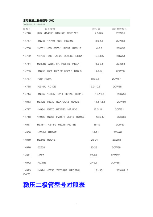
常用稳压二极管型号(转)2008-05-12 15:06:44原型号国外型号稳压值国内替代型号1N746 H23 MA4030 RD417E RD217EB 2.5-3.5 2CW511N747 1N748 1N749 HZ4 RD3.9E 3.9-4.5 2CW521N750 1N751 HZ5 05Z5.1 RD5A RD5.1E 4-5.8 2CW531N752 1N753 HZ6 HZ6.2E 05Z5.6E RD6A 5.5-6.5 2CW541N754 HZ6.8E 02Z6。
8A RD6.8E RD7A 6.2-7.5 2CW551N755 1N756 HZ7 HZ7.5E 05Z7.5 RD7.5 7-8.5 2CW561N757 HZ9 RD9A 8.5-9.5 2CW571N758 HZ10A RD10E 9.2-10.5 2CW581N714 1N962 1S335 HZ11 HZ11E RD11E 10-11.8 2CW591N963 HZ12E 05Z12 BZX79C12 RD12E 11.5-12.5 2CW601N717 1N964 1S270 HZ12B2 MA1130 12.2-14 2CW611N718 1N965 1N966 HZ15-1 05Z15 RD15E 13.5-17 2CW621N967 HZ18-1 HZ18-2 05Z18 RD18E 16-19 2CW631N968 HZ20-1 RD20E 18-21 2CW641N969 HZ24E RD24E 20-24 2CW651N970 02Z24 23-26 2CW661N971 HZ27 25-28 2CW671N972 RD31E 27-32 2CW681N973 1N974 HZ733 ZX0249E UPC574J 31-35 2CW69 2 CW70稳压二极管型号对照表美标稳压二极管型号1N4727 3V01N4728 3V31N4729 3V61N4730 3V91N4731 4V31N4732 4V71N4733 5V11N4734 5V61N4735 6V21N4736 6V81N4737 7V51N4738 8V21N4739 9V11N4740 10V1N4741 11V1N4742 12V1N4743 13V1N4744 15V1N4745 16V1N4746 18V1N4747 20V1N4748 22V1N4749 24V1N4750 27V1N4751 30V1N4752 33V1N4753 36V1N4754 39V1N4755 43V1N4756 47V1N4757 51V需要规格书请到以下地址下载,om/products/Rectifiers/Diode/Zener/经常看到很多板子上有M记的铁壳封装的稳压管,都是以美标的1N系列型号标识的,没有具体的电压值,刚才翻手册查了以下3V至51V的型号与电压的对照值,希望对大家有用1N4727 3V01N4728 3V31N4729 3V61N4730 3V91N4731 4V31N4732 4V71N4733 5V11N4735 6V21N4736 6V81N4737 7V51N4738 8V21N4739 9V11N4740 10V1N4741 11V1N4742 12V1N4743 13V1N4744 15V1N4745 16V1N4746 18V1N4747 20V1N4748 22V1N4749 24V1N4750 27V1N4751 30V1N4752 33V1N4753 36V1N4754 39V1N4755 43V1N4756 47V1N4757 51VDZ是稳压管的电器编号,是和1N4148和相近的,其实1N4148就是一个0.6V的稳压管,下面是稳压管上的编号对应的稳压值,有些小的稳压管也会在管体上直接标稳压电压,如5V6就是5.6V的稳压管。
三端稳压管型号稳压值及详细资料
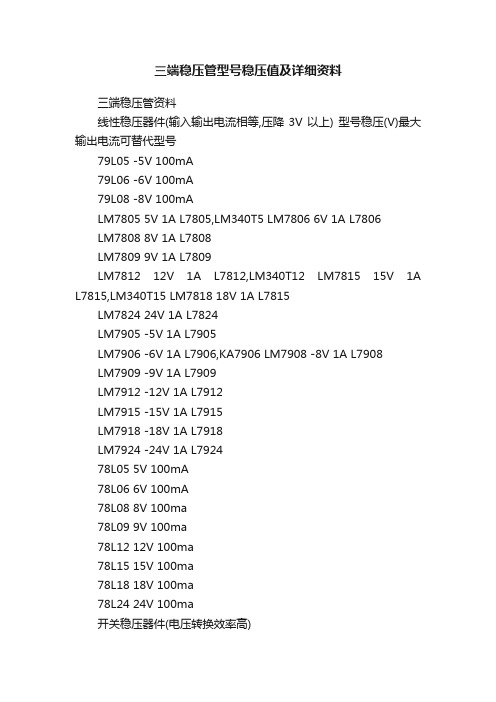
三端稳压管型号稳压值及详细资料三端稳压管资料线性稳压器件(输入输出电流相等,压降3V以上) 型号稳压(V)最大输出电流可替代型号79L05 -5V 100mA79L06 -6V 100mA79L08 -8V 100mALM7805 5V 1A L7805,LM340T5 LM7806 6V 1A L7806LM7808 8V 1A L7808LM7809 9V 1A L7809LM7812 12V 1A L7812,LM340T12 LM7815 15V 1A L7815,LM340T15 LM7818 18V 1A L7815LM7824 24V 1A L7824LM7905 -5V 1A L7905LM7906 -6V 1A L7906,KA7906 LM7908 -8V 1A L7908LM7909 -9V 1A L7909LM7912 -12V 1A L7912LM7915 -15V 1A L7915LM7918 -18V 1A L7918LM7924 -24V 1A L792478L05 5V 100mA78L06 6V 100mA78L08 8V 100ma78L09 9V 100ma78L12 12V 100ma78L15 15V 100ma78L18 18V 100ma78L24 24V 100ma开关稳压器件(电压转换效率高)型号说明最大输出电流LM1575T-3.3 3.3V简易开关电源稳压器 1ALM1575T-5.0 5V简易开关电源稳压器 1ALM1575T-12 12V简易开关电源稳压器1ALM1575T-15 15V简易开关电源稳压器1ALM1575T-ADJ 简易开关电源稳压器(可调 1.23V~37V) 1A LM1575HVT-3.3 3.3V简易开关电源稳压器 1ALM1575HVT-5.0 5V简易开关电源稳压器 1ALM1575HVT-12 12V简易开关电源稳压器1A LM1575HVT-15 15V简易开关电源稳压器1A LM1575HVT-ADJ 简易开关电源稳压器(可调1.23V~37V) 1A LM2575T-3.3 3.3V简易开关电源稳压器 1A LM2575T-5.0 5V简易开关电源稳压器 1A。
表贴稳压二极管选型条件
表贴稳压二极管选型条件全文共四篇示例,供读者参考第一篇示例:表贴稳压二极管是一种常用的电子元器件,主要用于稳定电压。
在电路设计中,选型是非常重要的一步,因为选用适合的稳压二极管能够有效保护电路及元器件,确保电路的稳定运行。
本文将介绍表贴稳压二极管选型的条件及注意事项。
表贴稳压二极管的选型应考虑以下几个因素:1. 工作电压范围:稳压二极管的工作电压范围是指其能稳定工作的最大和最小电压值。
在选择稳压二极管时,应根据电路的实际工作电压来确定合适的工作电压范围。
2. 稳定性:稳压二极管的稳定性是指其输出电压随输入电压变化的能力。
在选型时,应选择具有较高稳定性的稳压二极管,以确保电路的稳定性。
3. 最大额定电流:稳压二极管能够承受的最大电流称为最大额定电流,选型时应根据电路所需的电流进行选择。
4. 温度系数:稳压二极管的温度系数是指其输出电压随温度变化的程度。
较低的温度系数可以提高稳压二极管的稳定性。
5. 封装类型:表贴稳压二极管通常采用SOT-23或SOT-89等封装类型,应根据实际需求选择合适的封装类型。
在选型时,还需要注意以下几点:1. 确定电路需求:在选型前,需要充分了解电路的需求,包括工作电压、电流等参数。
2. 参考厂家数据手册:在选型时,应参考稳压二极管的厂家数据手册,查找相关参数并进行比较。
3. 进行实际测试:在确定选型后,最好进行实际测试,以确保所选稳压二极管符合电路的要求。
4. 注意稳压二极管的额定功率:稳压二极管的额定功率不宜超过其极限值,否则会影响其稳定性和寿命。
第二篇示例:表贴稳压二极管是一种常见的电子元件,用于稳定电压并保护电路免受过压的损害。
在电子产品的设计中,选用合适的表贴稳压二极管对于保证电路稳定性和可靠性至关重要。
那么,在进行表贴稳压二极管的选型时,需要考虑哪些条件呢?本文将为您详细介绍。
要考虑的是表贴稳压二极管的工作电压范围。
表贴稳压二极管主要用于保护电路免受过压的损害,因此选型时需要确保其能够承受电路中出现的最大工作电压。
常用稳压二极管的参数规格

常用稳压二极管的参数规格-稳压二极管参数大全[ 来源:不详| 作者:佚名| 时间:2008-3-27 1:17:23 | 浏览:本日:1 本周:24 本月:59 总数:118 ] 常用的稳压二极管常用的国产稳压二极管有2CW系列和2DW系列,常用的国产稳压二极管稳压二极管参数见表4-16和表4-17。
常用的进口稳压二极管有1N41××系列、1N46××系列、1N47××系列、1N52××系列、1N59××系列、1N6××系列、1N700系列、1N900系列、MTZ系列、MTZJ系列、RLZ系列、RLZJ系列及HZ系列、RD系列、05Z系列、PTZ系列、DTZ系列、,常用的进口稳压二极管参数见表4-18~表4-22。
快恢复二极管参数型号品牌电流电压时间极性IN5817GJ1A20V10nsIN5819GJ1A40V10nsIN5819MOT1A40V10nsIN5822MOT3A40V10ns21D-06FUI3A60V10nsSBR360GI3A60V10nsC81-004FUI3A40V10ns8TQ080IR8A80V10ns单管MBR1045MOT10A45V10ns单管MBR1545CTMOT15A45V10ns双管MBR1654MOT16A45V10ns双管16CTQ100IR16A100V10ns双管MBR2035CTMOT20A35V10ns双管MBR2045CTMOT20A45V10ns双管MBR2060CTMOT20A60V10ns双管MBR20100CTIR20A100V10ns双管025CTQ045IR25A45V10ns双管30CTQ045IR30A45V10ns双管C85-009*FUI20A90V10ns双管D83-004*FUI30A40V10ns双管D83-009*FUI30A90V10ns双管MBR4060*IR40A60V10ns双管MBR30045MOT300A45V10ns MUR120MOT1A200V35nsMUR160MOT1A600V35nsMUR180MOT1A800V35nsMUR460MOT4A600V35nsBYV95PHI1.5A1000V250nsBYV27-50PHI2A55V25nsBYV927-100PHI2A100V25nsBYV927-300PHI2A300V25ns BYW76PHI3A1000V200nsBYT56GPHI3A600V100nsBYT56MPHI3A1000V100nsBYV26CPHI1A600V30nsBYV26EPHI1A1000V30nsFR607GI6A1000V200nsMUR8100MOT8A1000V35ns单管HFA15TB60IR15A600V35ns单管HFA25TB60IR25A600V35ns单管MUR30100HAR30A1000V35ns单管MUR30120HAR30A1200V35ns单管MUR1620PHI16A200V35ns双管MUR1620CTMOT16A200V35ns双管MUR1620PMOT16A200V35ns双管MUR1660CTMOT16A600V35ns双管HFA16TA600IR16A600V35ns双管MUR3030GI30A300V35ns双管MUR3040MOT30A400V35ns双管MUR3060MOT30A600V35ns双管HFA30TA600IR30A600V35ns双管MUR20040MOT200A400V35ns双管B92M-02FUI20A200V35ns单管C92-02FUI20A200V35ns双管D92M-02FUI30A200V35ns双管D92M-03FUI30A300V35ns双管DSE130-06DSET30A600V35ns双管DSE160-06DSET60A600V35ns双管原创文章:"/public/tool/kbview/kid/686/cid/1" 【请保留版权,谢谢!】文章出自电子元件技术网。
最全二极管资料手册

最全⼆极管资料⼿册⼀、常⽤BW系列稳压⼆极管参数与代换116种常⽤BW系列稳压⼆极管参数与代换116种型号最⼤耗散功率(W)稳定电压(V)最⼤⼯作电流(mA)可代换型号型号最⼤耗散功率(W)稳定电压(V)最⼤⼯作电流(mA)可代换型号BWA50A0.251832CW50.2CW50B,2CW9BWB39D0.53711.505W39V,2CW411,GY5-39BWA51A0.252.5712CW51B,2CW74010.605W43VBWA52A0.253.2552CWl1,2CW52,2CW52B BWB47D0.5449.71W46E,1W46G,1W46H,1W46FBWA530.254.25412CW53BBWB51D0.5488.91W53A,1W53B,1W53C,1W53DBW54/E0.255.5BWB56D0.5528.105W60VBWA55/E0.256.2331N709,2CW55,2CW55B BWB62D0.5587.32CW5264BWA560.257272CW15,2CW28-7.5,2CW56 BWB68D0.5646.705W75V,1/2W70-68V,1N6002 BWA57/E2CW28-9.1,2CW73BWB75D0.5706.11/2W80BWA58/E0.259.2232CW58A,2CW74,2CW74B BWB82D0.5775.51/2W90BWA59/E0.2510211N714,2CW18,2CW59 BWB91D0.5855.02CW526911.5192CW19,2CW60,2CW76A BWB100D0.5944.51/2W100BWA61/D/E0.2512.2161N716,2CW61,2CW77BBWB110D0.51044.11/2W110-110V,l/2W120,1N6025BWA62/D/E0.2513.5142CW20,2CW62B,2CW78 BWC50/D1380.2516132CW63,2DWI2H,2CW63B BWC51/D142181W50,2DW51BWA64/D/E0.2518112CW64B,2CW7KBWC52/D152151W60,2DW52BWA65/D0.2520101N721,2CW65,2DW12I BWC53/DBWA66/D0.252392CW20C,2CW65,2CW66 BWC54/D170111W80,2DW54BWA67/D0.252592CW67,2CW67BBWC55/D180101W90,2DW55BWA68/D0.252799091W100,2DW56BWA69/D0.252972CW69,2CW69BBWC57/D110081W110,2DW56-100V,2DW57BWA70/D0.253272CW70,2CW70B,2DW13C BWC58/D111071W120,2DW56-110V,2DW58BWA71/D0.252CW70C,2DW13DBWC59/D112061W130,2DW58-120V,2DW59BWA71E0.258.5252CW28-9.1,2CW57/BBWC60/D113561W140,2DW60BWA74E0.259.2232CW58/A/B,2CW74BWC61/D11456IW150,2DW6110212CW75B,2CW7HBWC62/D115551W160,2DW62BWA76E0.2511.5202CW19,2CW60/A,2CW76 BWC63/D116551W180,2DW63BWA77E0.2512.2182CW61,2CW61A,2CW77 BWC64/D11805BWA78E0.2513.5142CW20,2CW62/B,2CW78 BWC100A113302CW100,ZW100BWB2V40.52.2819105W2V4,2CW37-2.4,2CW382 BWC101A12.528020W101,ZW101BWB2V70.52.5016805W2V7,2CW37-2.7,2CW383 BWC1O212CW102,ZW1O2BWB3V00.52.815005W3V,2CW37-3.0,2CW384 BWCIO3/A141652CW103,2CW4V3,ZW103BWB3V30.53.113805W3V3,2CW37-3.3,BS73-3.3 BWC105/E16.21302CW105,1N4735BWB3V60.53.412605W3V6,2CW37-3.6,2CW3867.01102CW106,2DW2,BS63-7.5BWB3V90.53.711505W3V9,2CW37-3.9,2CW387 BWC1O7/E18.51002CW107,1N4739,2DW3BWB4V30.54.010605W4V3,2CW37-4.3,2CW21A BWClO9D/E110831N4740,2CW109,2DW5BWB4V70.54.4BWC110/D/E111.5762CW110,2CW138,ZW110BWB5V10.54.88905W5V1,2CW37-5.1,2CW390 BWC111/D/E112.2662CW111,ZW111BWB5V60.55.2812CW37-5.6,BS73-5.6,BZPD-5.6 BWC112/D/E113.5581W15V,2CW112,2CW286-15 BWB6V205W6V2,2CW37-6.2,2CW392 BWC113/D/E116522CW113,1N4745BWB6V80.56.46705W6V8,2CW37-6.8,2CW393 BWC114/D118472CW114,1N4746BWB7V50.57.0612CW21D,2CW37-7.5,2CW56 BWC115/D120412CW115,1N47477.75505W8V2,2CW37-8,22CW395 BWC116/D123382CW116,ZWl16BWB9V10.58.5502CW58,2CW73,2CW37-9.1 BWC117/D125352CW117,2W117BWB10E0.59.44605W10V,2CW37-10,2CW397 BWC118/D127BWB11E0.510.44005W11V,2CW37-11,2CW398 BWC119/D129302CW119,2W119BWB12D/E0.511.43805WI2V,2CW37-12,BS73-12 BWC12O/D132272CW120,ZWl20BWB13D/E0.512.4352CW400,BS73-13BWC121/D2CW121,ZW121BWB15D/E0.513.8302CW37-15,BS73-15 BWD80D333652CW149,2CW22NBWB16D/E0.515.3282CW37-16,BS73-16 BWD81D342502DW81,3W50BWB18D/E0.516.82552452DW82,3W80BWB20D/E0.518.82305W20V,2CW37-20,2CW404 BWD83D362402DW83,3W70BWB22D0.520.82105W22V,2CW37-22,2CW405 BWD84D370352DW84,3W80BWB24D0.505W24V,2CW406,RD24E BWD85D380302DW85,3W90BWB27D0.525.116.805W27V,2CW407,BZPD-27 BWD86D396252DW86BWB30D0.528.015.105W30V,2CW408,1N5255 BWD87D3100232DW87,3W1003113.805W33V,2CW409,W33A BWD88D3110202DW88,3W110BWB36D0.53412.605W36V,2CW410,2CW37-36 BWD89D3120202DW89,3W120型号最⼤耗散功率(W)稳定电压(V)最⼤⼯作电流(mA)可代换型号型号最⼤耗散功率(W)稳定电压(V)最⼤⼯作电流(mA)常⽤进⼝1N系列稳压⼆极管参数与代换90种型号最⼤耗散功率(W)稳定电压(V)最⼤⼯作电流(mA)可代换型号型号最⼤耗散功率(W)稳定电压(V)最⼤⼯作电流(mA)可代换型号1N5236/A/B0.57.5612CW105-7.5V,2CW52361N59870.531412CW51-3V,2CW52251N5237/A/B0.58.2552CW106-8.2V,2CW52373.31282CW51-3V3,2CW52261N5238/A/B0.58.7522CW106-8.7V,2CW5238 1N59890.53.61182GW51-3V6,2CW52271N5239/A/B0.59.1502CW107-9.1V,2CW5239 1N59900.53.91002CW52-3V9,2CW52281N5240/A/B0.5101N59910.54.3992CW52-4V3,2CW52291N5241/A/B0.511412CW109-11V,2CW5241 1N59920.54.7902CW53-4V7,2CW52301N5242/A/B0.512382CW11O-12V,2CW5242 1N59930.55.1832CW53-5V1,2CW5231 1N5243/A/B2CW111-13V,2CW5243 1N59940.55.6762CW53-5V6,2CW52321N5244/A/B0.514322CW111-14V,2CW5244 1N59950.56.2682CW54-6V2,2CW52341N5245/A/B0.515302CW112-15V,2CW5245 1N59960.56.8632CW54-6V8,2CW523516282CW112-16V,2CW5246 1N59970.57.5572CW55-7V5,2CW52361N5247/A/B0.517272CW113-17V,2CW5247 1N59980.58.2522CW55-8V2,2CW52371N5248/A/B0.518252CW113-l8V,2CW5248 1N59990.59.11N5249/A/B0.519242CW114-19V,2CW5249 1N60000.510432CW58-10V,2CW52401N5250/A/B0.520232CW114-20V,2CW5250 1N60010.511392CW59-11V,2CW52411N5251/A/B0.522212CW115-22V,2CW5251 1N60022CW60-12V,2CW52421N5252/A/B0.52419.12CW115-24V,2CW5252 IN60030.513332CW61-13V,2CW52431N5253/A/B0.52518.22CW116-25V,2CW5253 1N60040.515282CW62-15V,2CW52451N5254/A/B0.52716.816272GW62-16V,2CW52461N5255/A/B0.52816.22CW118-28V,2CW5255 1N60060.518242CW63-18V,2CW52481N5256/A/B0.53015.12CW119-30V,2CW5256 1N60070.520212CW64-20V,2CWS2SO1N5257/A/B0.52CW120-33V,2CW5257 1N60080.522192CW65-22V,2CW52511N57300.45.6652CW752IN60090.524182CW66-24V,2CW52521N57310.46.2622CW753,RD6.2EB1N60100.527162CW67-27V,2CW52546.8582CW754,2CW9571N60110.530142CW68-30V,2CW52561N57330.47.5522CW755,2CW9581N60120.533132CW69-33V,2CW52571N57340.48.2472CW756,2CW9591N60130.536121N57350.49.1422CW757,2CW9601N60140.539112CW71-39V,2CW52591N57360.410392CW758,2CW96l1N60150.5439.92CW72-43V,2GW52601N57370.411362CW9621N60160.50.5W47V,2CW52611N57380.412332CW7592,CW9631N60170.5518.30.5W51V,2CW52621N57390.413302CW760,2CW964,HZ-12C 1N60180.5567.60.5W56V,2CW52631N57400.415262CW965626.80.5W62V,2CW52651N57410.416242CW9661N60200.5686.30.5W68V,2CW52661N57420.418212CW9671N60210.5755.70.5W75V,2CW52671N57430.420IN60220.5825.20.5W82V,2CW52681N57440.422172GW9691N60230.5914.50.5W91V,2CW52701N57450.424152CW970,EQA02-25A 1N60240.51004.00.SW100V,2CW5271 1N57462CW971,HZS30E1N60250.51103.90.5W110V,2CW52721N57470.430112CW972,1/2W301N60260.51203.50.5W120V,2CW52731N57480.433102CW9731N60270.51303.30.5W130V3692CW9741N60280.51502.80.5W150V1N57500.43982CW9751N60290.51602.50.5W160V1N59850.52.41752CW50-2V4,2GW5221 1760300.51801N59860.52.71672CW50-2V7,2CW52231N60310.52001.00.5W200V型号最⼤耗散功率(W)稳定电压(V)最⼤⼯作电流(mA)可代换型号型号最⼤耗散功率(W)稳定电压(V)最⼤⼯作电流(mA)可代换型号常⽤进⼝BZ/EQ/BW系列稳压⼆极管参数与代换型号最⼤耗散功率(W)稳定电压(V)最⼤⼯作电流(mA)最⼤耗散功率(W)稳定电压(V)最⼤⼯作电流(mA)可代换型号BZPD-3.00.52.812505W3V、2CW384、2CW5224 EQA02-25A0.524~25181N5746、2CW971、HZS30EBZPD-3.30.53.111505W3V3、2CW37-3.3、HS73-3.3 EQA02-25C0.526~28152CW117、1N5254、2CW5254BZPD-3.60.505W3V6、2CW37-3.6、BS73-3.6 EQB01-05152002CW523、1N5231BZPD-3.90.53.89505W3V9、2CW37-3.9、2CW387 EQB01-06161802CW104、2CW5233BZPD-4.30.54.09005W4V3、2CW37-4.3、2CW388 EQB01-07171402CW105、2CW564.48505W4V7、2CW37-4.7、2CW389 EQBO1-08181202CW106、2CW134BZPD-5.10.54.88005W5V1、2CW37-5.1、2CW390 EQB01-09191102CW107、2CW135BZPD-5.60.55.2702CW37-5.6、BS73-5.6、2CW391 EQB01-10110100BZPD-6.20.55.86405W6V2、2CW37-6.2、2CW392 EQB01-11111902CW109、2CW137BZPD-6.80.56.45805W6V8、2CW37-6.8、2CW393 EQB01-12112802CW110、2CW138RZPD-7.50.57.0532CW56、2CW21D、BS73-7.5 EQB01-1312CW111、2CW139BZPD-8.20.57.74705W8V2、2CW37-8.2,2CW395 EQB01-14114702CW113A、2CW140-14VRZPD-9.10.58.5432CW37-9.1、2CW396EQB01-15115652CW113B、2CW14O-15VBZPD-100.59.4402CW37-10、05W10V、2CW39716602CW113C、2CW23A/BRZPD-110.510.43605W11V、2CW37-11、2CW398 EQB01-17117552CW114、2CW63-17VBZPD-120.511.43205W12V、2CW37-12、2CW399 EQB01-18118502GW114-18、2CW63-18VHZPD-130.512.4EQB0L-19119502CW114-19、2CW63-19VBZPD-150.513.8272CW37-15、RD15E,2CW401 EQB01-20120452CW115-20、2CW64-20VBZPD-160.515.3242CW37-16、BS73-16、2CW402 EQB01-21121452CW115-21、2CW64-21V BZPD-182CW37-18、RS73-18,2CW403 EQB01-22122402CW115-22、2CW64-22VBZPD-200.518.8202CW37-20,05W20V、2CW404 EQB01-23123402CW116-23、2CW144-23VBZPD-220.520.81805W22V、2CW37-22,2CW405 EQB01-24124402CW116-24、2C525222.71605W24V,RD24E、2CW406 EQB01-25125402CW116-25、2CW145-25VBZPD-270.525.11405W27V、RD27E、2CW407 EQB0l-26126352CW117-26、2CW145-26VRZXC5V10.54.88005W5V1、2CW37-5.1、2CW390 EQB01-28128BZXC7V50.57.5702CW5236、2CW55-7V5 EQB01-30130302CW118-30、2CW147-30VBZXC120.512402CW77、2CW61AEQB01-3213230µPC574,TAA550BZX79B5V0.45752CW13、05W5V1BWD90D2DW90、3W140RZX79B6V80.46.8552CW55A、1N71O BWD130336602CW130、2CW22BZX79B36V0.436102CW120-36V、BWC50D BWD131345002CW131、2CW22ABZX79C6V20.46.2605.54602CW132、2CW22BBZX79C200.420202CW23B、2CW23CBWD13336.24002CW133、2CW22CBZX83-150.513.8272CW37-15、BS73-15、RD15E BWD13437.03302CW134、2CW22DBZX83-5V10.5。
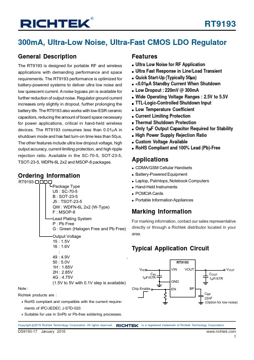
3.3v输出低压差线性稳压器DS9193数据手册
1
RT9193
Pin Configurations
(TOP VIEW)
VOUT
5
BP
4
2
3
EN GND VIN
1 2 3 7
6 5 4
BP NC VOUTΒιβλιοθήκη NC VIN NC VOUT
8 2 3 4 7 6 5
NC EN BP GND
VIN GND EN
WDFN-6L 2x2
Applications
Ordering Information
RT9193Package Type U5 : SC-70-5 B : SOT-23-5 J5 : TSOT-23-5 QW : WDFN-6L 2x2 (W-Type) F : MSOP-8 Lead Plating System P : Pb Free G : Green (Halogen Free and Pb Free) Output Voltage 15 : 1.5V 16 : 1.6V : 49 : 4.9V 50 : 5.0V 1H : 1.85V 2H : 2.85V 4G : 4.75V (1.5V to 5V with 0.1V step is available)
Marking Information
For marking information, contact our sales representative directly or through a Richtek distributor located in your area.
Typical Application Circuit
Function Block Diagram
EN Quick Start BP VREF
3.3V稳压IC方案HT7333规格书
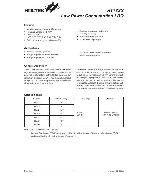
HT73XXLow Power Consumption LDOSelection TablePart No.Output VoltagePackageMarkingHT7318 1.8V TO-92SOT-8973XX-A (for TO-92)73XX-A (for SOT-89)HT7325 2.5V HT7327 2.7V HT7330 3.0V HT7333 3.3V HT7335 3.5V HT73505.0VNote:²XX ²stands for output voltages.For lead free devices,TO-92package will add a ²#²mark at the end of the date code,whereas SOT-89package will add a ²#²mark at the end of the marking.Rev.1.401January 12,2006Features·Ultra low quiescent current:3.5m A (typ.)·High input voltage (up to 12V)·Output voltage:1.8V,2.5V,2.7V,3.0V,3.3V,3.5V,5.0V·Output voltage accuracy:tolerance ±3%·Maximum output current:250mA ·Low dropout voltage ·Low temperature coefficient ·TO-92,SOT-89packageApplications·Battery-powered equipment ·Voltage regulator for microprocessor ·Voltage regulator for LAN cards·Wireless Communication equipment ·Audio/Video equipmentGeneral DescriptionThe HT73XX series is a set of three-terminal,low power,high voltage regulators implemented in CMOS technol-ogy.The series features extremely low quiescent cur-rent which is typically 3.5m A.They allow input voltages as high as 12V.The device provides large current with a significantly small dropout voltage.The HT73XX consists of a high-precision voltage refer-ence,an error correction circuit,and a current limited output driver.They are available with several fixed out-put voltages ranging from 1.8V to 5.0V.CMOS technol-ogy ensures low dropout voltage and low current consumption.Although designed primarily as fixed volt-age regulators,these devices can be used with external components to generate variable voltages and currents.Block DiagramPin AssignmentAbsolute Maximum RatingsSupply Voltage...........................V SS-0.3V to V SS+14V Storage Temperature...........................-50°C to125°C Power Consumption(*1)..................................500mW Operating Temperature..........................-40°C to85°C Power Consumption(*2)...................................500mWNote:These are stress ratings only.Stresses exceeding the range specified under²Absolute Maximum Ratings²may cause substantial damage to the device.Functional operation of this device at other conditions beyond those listed in the specification is not implied and prolonged exposure to extreme conditions may affect device reliabil-ity.*1:applied to TO-92*2:applied to SOT-89Rev.1.402January12,2006Electrical CharacteristicsHT7318,+1.8V Output Type Ta=25°CSymbol ParameterTest ConditionsMin.Typ.Max.Unit V IN ConditionsV OUT Output Voltage 2.8V I OUT=40mA 1.746 1.8 1.854V I OUT(MAX)Maximum Output Current 2.8V V OUT³1.62V150¾¾mA D V OUT*Load Regulation 2.8V1mA£I OUT£60mA¾4590mV V DROP**Dropout Voltage¾I OUT=40mA¾170¾mV I SS Quiescent Current 2.8V No load¾ 3.57m ALine Regulation¾I OUT=40mA2.8V£V IN£12V¾0.20.3%/VV IN Input Voltage¾¾¾¾12VTemperature Coefficient 2.8V I OUT=40mA-40°C<Ta<85°C¾±0.7¾mV/°CHT7325,+2.5V Output Type Ta=25°CSymbol ParameterTest ConditionsMin.Typ.Max.Unit V IN ConditionsV OUT Output Voltage 3.5V I OUT=40mA 2.425 2.5 2.575V I OUT(MAX)Maximum Output Current 3.5V V OUT³2.25V180¾¾mA D V OUT*Load Regulation 3.5V1mA£I OUT£60mA¾4590mV V DROP**Dropout Voltage¾I OUT=40mA¾110¾mV I SS Quiescent Current 3.5V No load¾ 3.57m ALine Regulation¾I OUT=40mA3.5V£V IN£12V¾0.20.3%/VV IN Input Voltage¾¾¾¾12VTemperature Coefficient 3.5V I OUT=40mA-40°C<Ta<85°C¾±0.7¾mV/°CHT7327,+2.7V Output Type Ta=25°CSymbol ParameterTest ConditionsMin.Typ.Max.Unit V IN ConditionsV OUT Output Voltage 3.7V I OUT=40mA 2.619 2.7 2.781V I OUT(MAX)Maximum Output Current 3.7V V OUT³2.43V200¾¾mA D V OUT*Load Regulation 3.7V1mA£I OUT£80mA¾4590mV V DROP**Dropout Voltage¾I OUT=40mA¾100¾mV I SS Quiescent Current 3.7V No load¾ 3.57m ALine Regulation¾I OUT=40mA3.7V£V IN£12V¾0.20.3%/VV IN Input Voltage¾¾¾¾12VTemperature Coefficient 3.7V I OUT=40mA-40°C<Ta<85°C¾±0.7¾mV/°CRev.1.403January12,2006Symbol Parameter Min.Typ.Max.UnitV IN ConditionsV OUT Output Voltage4V I OUT=40mA 2.913 3.09V I OUT(MAX)Maximum Output Current4V V OUT³2.7V250¾¾mA D V OUT*Load Regulation4V1mA£I OUT£80mA¾4590mV V DROP**Dropout Voltage¾I OUT=40mA¾95¾mV I SS Quiescent Current4V No load¾ 3.57m ALine Regulation¾I OUT=40mA4V£V IN£12V¾0.20.3%/VV IN Input Voltage¾¾¾¾12VTemperature Coefficient4V I OUT=40mA-40°C<Ta<85°C¾±0.7¾mV/°CHT7333,+3.3V Output Type Ta=25°CSymbol ParameterTest ConditionsMin.Typ.Max.Unit V IN ConditionsV OUT Output Voltage 4.3V I OUT=40mA 3.201 3.3 3.399V I OUT(MAX)Maximum Output Current 4.3V V OUT³2.97V250¾¾mA D V OUT*Load Regulation 4.3V1mA£I OUT£80mA¾4590mV V DROP**Dropout Voltage¾I OUT=40mA¾90¾mV I SS Quiescent Current 4.3V No load¾ 3.57m ALine Regulation¾I OUT=40mA4.3V£V IN£12V¾0.20.3%/VV IN Input Voltage¾¾¾¾12VTemperature Coefficient 4.3V I OUT=40mA-40°C<Ta<85°C¾±0.7¾mV/°CHT7335,+3.5V Output Type Ta=25°CSymbol ParameterTest ConditionsMin.Typ.Max.Unit V IN ConditionsV OUT Output Voltage 4.5V I OUT=40mA 3.395 3.5 3.605V I OUT(MAX)Maximum Output Current 4.5V V OUT³3.15V250¾¾mA D V OUT*Load Regulation 4.5V1mA£I OUT£80mA¾4590mV V DROP**Dropout Voltage¾I OUT=40mA¾80¾mV I SS Quiescent Current 4.5V No load¾ 3.57m ALine Regulation¾I OUT=40mA4.5V£V IN£12V¾0.20.3%/VV IN Input Voltage¾¾¾¾12VTemperature Coefficient 4.5V I OUT=80mA-40°C<Ta<85°C¾±0.7¾mV/°CRev.1.404January12,2006Symbol Parameter Min.Typ.Max.UnitV IN ConditionsV OUT Output Voltage6V I OUT=40mA 4.855 5.15V I OUT(MAX)Maximum Output Current6V V OUT³4.5V250¾¾mA D V OUT*Load Regulation6V1mA£I OUT£100mA¾4590mV V DROP**Dropout Voltage¾I OUT=40mA¾60¾mV I SS Quiescent Current6V No load¾ 3.57m ALine Regulation¾I OUT=40mA6V£V IN£12V¾0.20.3%/VV IN Input Voltage¾¾¾¾12VTemperature Coefficient6V I OUT=80mA-40°C<Ta<85°C¾±0.7¾mV/°CNote:²*²Regulation is measured at constant junction temperature,using pulsed ON time.²**²Dropout is measured at constant junction temperature,using pulsed ON time,and the criterion is V OUT in-side target value±2%.Application CircuitsRev.1.405January12,2006Package Information TO-92Outline DimensionsSymbolDimensions in milMin.Nom.Max.A170¾200B170¾200C500¾¾D11¾20E90¾110F45¾55G45¾65H130¾160I8¾18a4°¾6°Rev.1.406January12,2006SOT-89Outline DimensionsSymbolDimensions in milMin.Nom.Max.A173¾181B64¾72C90¾102D35¾47E155¾167F14¾19G17¾22H¾59¾I55¾63J14¾17Rev.1.407January12,2006Product Tape and Reel SpecificationsTO-92Reel Dimensions(Unit:mm)Rev.1.408January12,2006SOT-89Reel DimensionsSOT-89Symbol Description Dimensions in mmA Reel Outer Diameter180±1.0B Reel Inner Diameter62±1.5C Spindle Hole Diameter12.75+0.15D Key Slit Width 1.9±0.15T1Space Between Flange12.4+0.2T2Reel Thickness17-0.4Rev.1.409January12,2006TO-92Carrier Tape DimensionsTO-92Symbol Description Dimensions in mm I1Taped Lead Length(2.5)P Component Pitch12.7±1.0P0Perforation Pitch12.7±0.3P2Component to Perforation(Length Direction) 6.35±0.4F1Lead Spread 2.5+0.4-0.1F2Lead Spread 2.5+0.4-0.1D h Component Alignment0±0.1W Carrier Tape Width 18.0+1.0-0.5W0Hold-down Tape Width 6.0±0.5W1Perforation Position9.0±0.5W2Hold-down Tape Position(0.5)H0Lead Clinch Height16.0±0.5H1Component Height Less than24.7D0Perforation Diameter 4.0±0.2t Taped Lead Thickness0.7±0.2H Component Base Height19.0±0.5Note:Thickness less than0.38±0.05mm~0.5mmP0Accumulated pitch tolerance:±1mm/20pitches.()Bracketed figures are for consultation onlyRev.1.4010January12,2006SOT-89Carrier Tape DimensionsSOT-89Symbol Description Dimensions in mmW Carrier Tape Width 12.0+0.3-0.1P Cavity Pitch8.0±0.1E Perforation Position 1.75±0.1F Cavity to Perforation(Width Direction) 5.5±0.05D Perforation Diameter 1.5+0.1D1Cavity Hole Diameter 1.5+0.1P0Perforation Pitch 4.0±0.1P1Cavity to Perforation(Length Direction) 2.0±0.10A0Cavity Length 4.8±0.1B0Cavity Width 4.5±0.1K0Cavity Depth 1.8±0.1t Carrier Tape Thickness0.30±0.013C Cover Tape Width9.3Rev.1.4011January12,2006。
- 1、下载文档前请自行甄别文档内容的完整性,平台不提供额外的编辑、内容补充、找答案等附加服务。
- 2、"仅部分预览"的文档,不可在线预览部分如存在完整性等问题,可反馈申请退款(可完整预览的文档不适用该条件!)。
- 3、如文档侵犯您的权益,请联系客服反馈,我们会尽快为您处理(人工客服工作时间:9:00-18:30)。
Zener DiodesFEATURES•Silicon planar power Zener diodes•For use in stabilizing and clipping circuits withhigh power rating•Standard Zener voltage tolerance is ± 5 %•Material categorization:For definitions of compliance please see/doc?99912APPLICATIONS•Voltage stabilizationPRIMARY CHARACTERISTICSPARAMETER VALUE UNITV Z range nom. 3.3 to 100VTest current I ZT 2.5 to 76mAV Z specification Thermal equilibriumInt. construction SingleORDERING INFORMATIONDEVICE NAME ORDERING CODE TAPED UNITS PER REEL MINIMUM ORDER QUANTITY 1N4728A to 1N4764A1N4728A to 1N4764A -series-TR5000 per 13" reel25 000/box1N4728A to 1N4764A1N4728A to 1N4764A-series-TAP 5000 per ammopack(52 mm tape)25 000/boxPACKAGEPACKAGE NAME WEIGHT MOLDING COMPOUNDFLAMMABILITY RATINGMOISTURE SENSITIVITYLEVELSOLDERING CONDITIONSDO-41310 mg UL 94 V-0MSL level 1(according J-STD-020)260 °C/10 s at terminalsABSOLUTE MAXIMUM RATINGS (T amb = 25 °C, unless otherwise specified)PARAMETER TEST CONDITION SYMBOL VALUE UNITPower dissipation Valid provided that leads at a distance of 4 mmfrom case are kept at ambient temperatureP tot1300mWZener current I Z P V/V Z mAThermal resistance junction to ambient air Valid provided that leads at a distance of 4 mmfrom case are kept at ambient temperatureR thJA110 K/WJunction temperature T j175°C Storage temperature range T stg- 65 to + 175°C Forward voltage (max.)I F = 200 mA V F 1.2VNotes(1)Based on DC measurement at thermal equilibrium while maintaining the lead temperature (T L) at 30 °C + 1 °C, 9.5 mm (3/8") from the diode body(2)Valid provided that electrodes at a distance of 4 mm from case are kept at ambient temperature (3)t p= 10 ms.ELECTRICAL CHARACTERISTICS (T amb = 25 °C, unless otherwise specified)PART NUMBERZENER VOLTAGERANGE (1)TEST CURRENT REVERSE LEAKAGECURRENTDYNAMIC RESISTANCE f = 1 kHz SURGE CURRENT (3)REGULATOR CURRENT (2)V Z at I ZT1I ZT1I ZT2I R at V RZ ZT at I ZT1Z ZK at I ZT2I R I ZM V mAmAμA VmAmA NOM.MAX.TYP.MAX.MAX.1N4728A 3.376110011040013802761N4729A 3.669110011040012602521N4730A 3.9641501940011902341N4731A 4.3581101940010702171N4732A 4.753110185009701931N4733A 5.149110175508901781N4734A 5.645110256008101621N4735A 6.241110327007301461N4736A 6.8371104 3.57006601331N4737A 7.5340.510547006051211N4738A 8.2310.5106 4.57005501101N4739A 9.1280.510757005001001N4740A 10250.25107.67700454911N4741A 11230.2558.48700414831N4742A 12210.2559.19700380761N4743A 13190.2559.910700344691N4744A 15170.25511.414700304611N4745A 1615.50.25512.216700285571N4746A 18140.25513.720750250501N4747A 2012.50.25515.222750225451N4748A 2211.50.25516.723750205411N4749A 2410.50.25518.225750190381N4750A 279.50.25520.635750170341N4751A 308.50.25522.8401000150301N4752A 337.50.25525.1451000135271N4753A 3670.25527.4501000125251N4754A 39 6.50.25529.7601000115231N4755A 4360.25532.7701500110221N4756A 47 5.50.25535.880150095191N4757A 5150.25538.895150090181N4758A 56 4.50.25542.6110200080161N4759A 6240.25547.1125200070141N4760A 68 3.70.25551.7150200065131N4761A 75 3.30.25556175200060121N4762A 8230.25562.2200300055111N4763A 91 2.80.25569.2250300050101N4764A1002.50.255763503000459BASIC CHARACTERISTICS (T amb = 25 °C, unless otherwise specified)Fig. 1 - Admissible Power Dissipation vs. Ambient TemperatureP tot = f (T amb)PACKAGE DIMENSIONS in millimeters (inches): DO-41_1N47xxLegal Disclaimer Notice VishayDisclaimerALL PRODU CT, PRODU CT SPECIFICATIONS AND DATA ARE SU BJECT TO CHANGE WITHOU T NOTICE TO IMPROVE RELIABILITY, FUNCTION OR DESIGN OR OTHERWISE.Vishay Intertechnology, Inc., its affiliates, agents, and employees, and all persons acting on its or their behalf (collectively,“Vishay”), disclaim any and all liability for any errors, inaccuracies or incompleteness contained in any datasheet or in any other disclosure relating to any product.Vishay makes no warranty, representation or guarantee regarding the suitability of the products for any particular purpose or the continuing production of any product. To the maximum extent permitted by applicable law, Vishay disclaims (i) any and all liability arising out of the application or use of any product, (ii) any and all liability, including without limitation special, consequential or incidental damages, and (iii) any and all implied warranties, including warranties of fitness for particular purpose, non-infringement and merchantability.Statements regarding the suitability of products for certain types of applications are based on Vishay’s knowledge of typical requirements that are often placed on Vishay products in generic applications. Such statements are not binding statements about the suitability of products for a particular application. It is the customer’s responsibility to validate that a particular product with the properties described in the product specification is suitable for use in a particular application. Parameters provided in datasheets and/or specifications may vary in different applications and performance may vary over time. All operating parameters, including typical parameters, must be validated for each customer application by the customer’s technical experts. Product specifications do not expand or otherwise modify Vishay’s terms and conditions of purchase, including but not limited to the warranty expressed therein.Except as expressly indicated in writing, Vishay products are not designed for use in medical, life-saving, or life-sustaining applications or for any other application in which the failure of the Vishay product could result in personal injury or death. Customers using or selling Vishay products not expressly indicated for use in such applications do so at their own risk. Please contact authorized Vishay personnel to obtain written terms and conditions regarding products designed for such applications. No license, express or implied, by estoppel or otherwise, to any intellectual property rights is granted by this document or by any conduct of Vishay. Product names and markings noted herein may be trademarks of their respective owners.Material Category PolicyVishay Intertechnology, Inc. hereby certifies that all its products that are identified as RoHS-Compliant fulfill the definitions and restrictions defined under Directive 2011/65/EU of The European Parliament and of the Council of June 8, 2011 on the restriction of the use of certain hazardous substances in electrical and electronic equipment (EEE) - recast, unless otherwise specified as non-compliant.Please note that some Vishay documentation may still make reference to RoHS Directive 2002/95/EC. We confirm that all the products identified as being compliant to Directive 2002/95/EC conform to Directive 2011/65/EU.Vishay Intertechnology, Inc. hereby certifies that all its products that are identified as Halogen-Free follow Halogen-Free requirements as per JEDEC JS709A standards. Please note that some Vishay documentation may still make reference to the IEC 61249-2-21 definition. We confirm that all the products identified as being compliant to IEC 61249-2-21 conform to JEDEC JS709A standards.。
