饲料添加剂80%标准
ESR-80

Optical Systems Division St. Paul3Optical Systems DivisionHandheldCustomer Quality Specification ESR-80 Enhanced Specular Reflector3Optical Systems DivisionHandheldCustomer Quality SpecificationESR-80 Enhanced Specular ReflectorTable of Contents1.0Scope2.0Function3.0Material4.0Structure5.0Definitions6.0Physical Characteristics7.0Optical Characteristics8.0Appearance9.0Measurement10.0Environmental Testing11.0Patent12.0Packaging13.0Film Handling14.0Warranty Period and Storage Conditions1.0 ScopeThis document provides customer specifications for 3M Enhanced Specular ReflectorESR-802.0 FunctionESR-80 is a highly specular reflective multilayer optical film used as the bottom reflector in backlight constructions of liquid crystal displays (LCD’s). When used in an LCDbacklight, ESR improves brightness of the LCD. ESR-80 is a slightly thicker version ofstandard ESR designed to reduce wetout and improve warp.3.0 Material3.1ESR-80 is a multilayer polyester-based film.3.2Protective film is applied to both sides of ESR-80.4.0 Structure4.1Cross section image not to scale. Values in section 4 are typical values but notproperty limits.(Reflective side)5.0 Definitions5.1Optical5.1.1Reflectivity: The average of reflectivity for 400nm to 800nm measured in2 nm intervals.5.2Cosmetic5.2.1Defect: Contamination, distortion and others that may affect theperformance of ESR-80. Dust or lint on the surface of ESR-80 that iseasily removed by wiping and/or air flow is excluded.5.2.2Point Defect: dark or light colored opaque, transparent or translucent spotwith defined edges. The size of a defect is judged by average diameter“D” below.5.2.3Line Defect: Defect observed in the shape of a line, where the length oflong side exceeds 3 times the length of the short side.5.2.4Fitness For Use (FFU): Accept/reject decision made based on a part beingfit for use in an application.6.0 Physical Characteristics6.1Thickness: 82µm ± 7µm (without protective film)6.2Part dimensions: Per approved customer drawing7.0 Optical CharacteristicsReflectivity Minimum 97.5%8.0 Appearance8.1Inspection condition: Cosmetic quality will be evaluated using FFU criteria8.1.1FFU Inspection for defects not defined in section 8.2.8.1.1.1Reflected diffuse white light with ESR-80 reflective side up.8.1.1.2Inside of 0.5 mm from the part edges excluding tab and PT tapeareas.8.1.1.3Minimum viewing distance from sample to eye of 25cm.8.2SpecificationItem Specification Criteria Allowable number ofdefectsDefect Accept if not visible in customer LCD module no limitPoint Defect Accept if not visible in customer LCD module or ifD ≤ 0.80mmAccept if not visible in customer LCD module or if0.80mm < D ≤ 1.1mm no limit1Line Defect Accept if not visible in customer LCD module no limit8.3Acceptance criteria8.3.1If a defect is visible per section 8.1, refer to the size requirement shown inthe table in section 8.2.8.3.2If the defect is not visible per section 8.1, the part is acceptable.8.3.3If the defect (dust, lint, fiber, or contamination) can be removed byair-blowing the part with ionized air, the part is acceptable.9.0 MeasurementNote: Reflectivity depends on the backlight material, design, and lighting efficiency.MethodReflectivity Sample: 75 mm x 75 mmReference Standard: NIST 2054 specular reflectorEquipment: Spectrophotometer equipped with an integrating sphere.Procedure: Reflectivity equals the average reflectivity over 400nm to800nm measured in 2 nm intervals10.0 Environmental Testing10.1Testing conditionESR-80 is tested under the following conditions with film free floating.Test ConditionHumidity resistance65° C, 95% relative humidity, 1000 hoursHeat resistance85° C for 1000 hoursCold resistance-40° C for 1000 hoursThermal shock85° C for 1 hr to -40C for 1 hr, 100 cycles10.2SpecificationItem JudgmentAppearance No significant appearance changeChange of reflectivity Minimum 95% of initial value11.0 PatentThis product, uses thereof, or its manufacture may be covered by one or more of thepatents listed on the package labels.12.0 PackagingProduct is delivered with a protective film on both sides of the ESR-80. The labelincludes the following information:12.1Product name12.23M Part Number12.3Quantity12.4Lot number12.5Patent Numbers13.0 Film Handling13.1Store parts flat and in original packaging.13.2Avoid applying pressure or resting objects on the product to prevent marking,denting or deforming the surface.13.3Wear gloves to prevent fingerprints or nail marks. Hold product by the edges toprevent touching display area. Do not slide the product.13.4Product must be stored away from direct sunlight.14.0 Warranty Period and Storage Conditions3M warrants that the products produced to this specification will meet this specificationfor twelve (12) months after the date of receipt at the purchaser location provided that the product is stored flat in accordance with the requirements in section 13.0 above and in the original package under the following conditions: temperature of 20 ±10°C and at arelative humidity of 45 ±15%. If product is shown to be defective during this warrantyperiod, 3M’s sole liability and purchaser’s exclusive remedy is, at 3M’s option, for 3M to refund the purchase price of the product or provide replacement product in the quantityshown to be defective.3M makes no additional warranties, express or implied, including but not limited to, any implied warranties of merchantability or fitness for a particular purpose. Inparticular, but without limitation, 3M makes no representations or warranties concerning the effective life of the products or their ability to survive user’s environmental testing.Purchaser is responsible for determining whether the 3M products are fit for thepurchaser’s particular purpose and suitable for the purchaser’s method of production.3M shall not be liable for any loss or damages, whether non-specified direct,indirect, special, incidental or consequential (including downtime, loss of profits orgoodwill) regardless of the legal theory asserted.。
高通405080平台索网测试方法
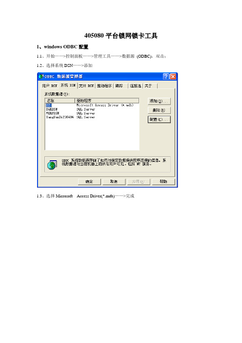
405080平台锁网锁卡工具1、windows ODBC配置1.1、开始——>控制面板——>管理工具——>数据源(ODBC),双击;1.2、选择系统DSN——>添加1.3、选择Microsoft Access Driver(*.mdb)——>完成1.4、数据源名:随便起,比如:0011.5、数据库:点击‘选择’按钮,在目录中寻找lock文件所在地,找到lockdb.mdb—〉确定.1.6、系统DNS中显示所添加的名称001注意:lock文件夹位置更改之后,ODBC数据源就要重新配置。
2、启动锁网锁卡软件2.1、启动计算机,并且在PC的USB口插入与本软件配套的ekey卡;2.2、在相应文件夹中找到“LockSoftware_405080test_NoKeyV1.00.00.exe”文件,双击该文件,启动程序。
如图1图1请注意,主界面右上方有两个按钮“中文版本”和“英文版本”,点击它们可以使程序的显示语言在中文和英文间切换3、软件主界面介绍:3.1、串口配置信息主界面左上方的串口选择栏,是供用户选择当前手机对应的端口的。
用户通过下拉框选择手机对应的正确的COM口,这里选择DIAG 口,这时程序便会开始在当前端口寻找手机,这期间右侧的图标一直显示。
当程序在当前端口找到手机后,右侧图标会变成。
3.2、数据库设置项在串口配置区下面有一个按钮,名称填写在数据源配置中的名称即可,用户名和密码均为空格。
如下图图24、锁网锁卡数据设置数据库配置按钮下面是锁网数据设置区域,如下图所示。
图3用户在这里输入要锁网的MCC\MNC数据以及锁卡的EF_GID1、file_size等数据。
当前生产线上的版本将这里的输入框全部disable,里面已经设好缺省值,不用用户输入,也不能输入。
MMC为460,MNC移动为0和2,联通为1,移动只需要设置前2项。
5、当前操作模式选择在锁网锁卡数据设置区域右侧是当前操作选择,如下图所示图4用户通过选择可以确定当前的操作是针对锁网还是锁卡。
RIGOL DM3058数字万用表 说明书
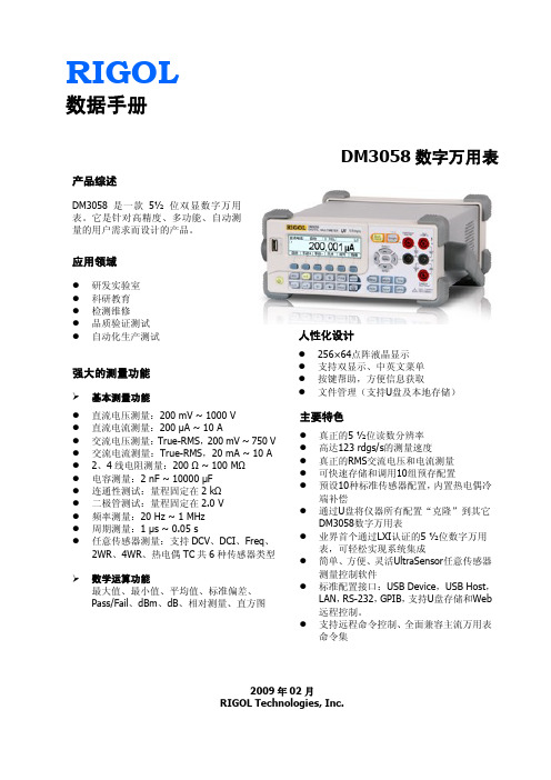
RIGOL 数据手册DM3058数字万用表2009年02月RIGOL Technologies, Inc.产品综述DM3058是一款5½ 位双显数字万用表。
它是针对高精度、多功能、自动测量的用户需求而设计的产品。
应用领域● 研发实验室 ● 科研教育 ● 检测维修 ● 品质验证测试 ●自动化生产测试强大的测量功能基本测量功能 ● 直流电压测量:200 mV ~ 1000 V ● 直流电流测量:200 μA ~ 10 A ● 交流电压测量:True-RMS ,200 mV ~ 750 V ● 交流电流测量:True-RMS ,20 mA ~ 10 A ● 2、4线电阻测量:200 Ω ~ 100 M Ω ● 电容测量:2 nF ~ 10000 μF ● 连通性测试:量程固定在2 k Ω ● 二极管测试:量程固定在2.0 V ● 频率测量:20 Hz ~ 1 MHz ● 周期测量:1 μs ~ 0.05 s●任意传感器测量:支持DCV 、DCI 、Freq 、 2WR 、4WR 、热电偶TC 共6种传感器类型数学运算功能最大值、最小值、平均值、标准偏差、Pass/Fail 、dBm 、dB 、相对测量、直方图主要特色● 真正的5 ½位读数分辨率 ● 高达123 rdgs/s 的测量速度● 真正的RMS 交流电压和电流测量 ● 可快速存储和调用10组预存配置 ● 预设10种标准传感器配置,内置热电偶冷端补偿● 通过U 盘将仪器所有配置“克隆”到其它DM3058数字万用表● 业界首个通过LXI 认证的5 ½位数字万用表,可轻松实现系统集成● 简单、方便、灵活UltraSensor 任意传感器测量控制软件●标准配置接口:USB Device ,USB Host ,LAN ,RS-232,GPIB ,支持U 盘存储和Web 远程控制。
●支持远程命令控制、全面兼容主流万用表命令集人性化设计● 256×64点阵液晶显示 ● 支持双显示、中英文菜单 ● 按键帮助,方便信息获取●文件管理(支持U 盘及本地存储)预设模式 Pass/Fail独特的任意传感器功能 LXI 认证&Web 远程控制简单、方便、灵活的控制软件灵活方便的双显功能可使您的测量工作达到事半功倍的效果。
Spectra Precision SP80 GNSS接收器产品介绍说明书

The Most Connected GNSS Receiver SP80 GNSS ReceiverSP80GNSS ReceiverThe Spectra Precision SP80 is a next generation GNSS receiver that combines decades of GNSS RTK technology with revolutionary new GNSS processing. Featuring the new 240-channel “6G”chipset combined with the patented Z-Blade technology, the SP80 system is optimized for tracking and processing signals from all GNSS constellations in challenging environments.As the most connected GNSS receiver in the industry, the SP80 offers a unique combination of integrated 3.5G cellular, Wi-Fi and UHF communications with SMS, email and anti-theft technology.These powerful capabilities, packaged in an ultra-rugged housing andpatented antenna design with unlimited operation time (hot-swappablebatteries), make SP80 an extremely versatile turnkey solution.Key Features■■Patented Z-Blade technology ■■240-channel 6G ASIC ■■Hot-swappable batteries ■■Internal TRx UHF radio ■■ 3.5G cellular modem ■■Built-in WiFi communication ■■SMS and e-mail alerts ■■Anti-theft technology ■■Backup RTK ■■RTK Bridge ■■eLevel technology■■Trimble RTX correction servicesS P 80Patented inside-the-rod mounted UHF antenna designUnique 6G GNSS-centric TechnologyPatented Z-Blade processing technology running on a nextgeneration Spectra Precision 240-channel 6G ASIC fully utilizesall 6 GNSS systems: GPS, GLONASS, BeiDou, Galileo, QZSS andSBAS. Unlike GPS-centric technology which requires a minimumnumber of GPS satellites for GNSS processing, Z-Blades uniqueGNSS-centric capability optimally combines GNSS signals withoutdependency on any specific GNSS system; this allows SP80 tooperate in GPS-only, GLONASS-only or BeiDou-only mode ifneeded. In addition, SP80 supports the recently approved RTCM3.2 Multiple Signal Messages (MSM), a standardized definitionfor broadcasting all GNSS signals from space, regardless oftheir constellation. This protects the surveyor’s investment wellinto the future by providing superior performance and improvedproductivity as new signals become available.SMS and Email MessagingSP80 has a unique combination of communication technologiesincluding an integrated 3.5G GSM/UMTS modem, Bluetooth and Wi-Fi connectivity, and optional internal UHF transmit radio. The cellularmodem may be used for SMS (text message) and e-mail alerts as wellas regular Internet or VRS connectivity. SMS (text messages) can beused to monitor and configure the receiver. Likewise, SP80 can use allavailable RTK correction sources and connect to the Internet from thefield using WiFi hotspots, where available. The internal UHF transmit/receive radio allows for quick and easy setup as a local base station.This saves time and increases the surveyor’s efficiency.Anti-Theft ProtectionA unique anti-theft technology secures SP80when installed as a field base station in remoteor public places and can detect if the product isdisturbed, moved or stolen. This technology allowsthe surveyor to lock the device to a specific locationand make it unusable if the device is moved elsewhere. In this case,SP80 will generate an audio alert and show an alert message on itsdisplay. Furthermore, a SMS or e-mail will be sent to the surveyor’smobile phone or computer and provides the receiver’s currentcoordinates allowing tracking of its position and facilitating recoveryof the receiver. SP80’s anti-theft technology provides surveyors withremote security and peace of mind.The Most Powerful Tool forReliable Field UseThe SP80’s rugged housing, created by Spectra Precision’sengineering design lab in Germany, incorporates a host of practicalinnovations. Dual hot-swappable batteries can be easily exchangedin the field as a one hand operation for an interruption-free workingday, ensuring surveyors remain productive until the job is done. Theimpact-resistant glass-fiber reinforced casing, designed to withstand2m pole drops and waterproof to IP67, ensures that SP80 canhandle the toughest outdoor conditions. The patented UHF antenna,set inside the rugged carbon fiber rod, extends the range of RTKradio performance at the same time as armoring protection. Thesunlight-readable display offers instant access to key information likethe number of satellites, RTK status, battery charge and availablememory. With eLevel technology, the user is able to focus in oneplace when leveling and measuring as well as automatically storemeasurements when the receiver is level. These powerful designfeatures combine to make SP80 the most capable, most reliableGNSS receiver, backed by a comprehensive standard 2 year warranty.The Spectra PrecisionExperienceWith the most advanced and rugged field datacollectors from Spectra Precision, surveyors getmaximum productivity and reliability every day.Spectra Precision Survey Pro or FAST Surveysoftware is specifically tailored for the SP80GNSS receiver providing easy-to-use, yetpowerful GNSS workflows, letting the surveyorconcentrate on getting the job done. SpectraPrecision Survey Office Software provides a complete office suitefor post-processing GNSS data and adjusting survey data, as wellas exporting the processed results directly back to the field or toengineering design software packages. Combined with SpectraPrecision field and office software, SP80 is a very powerful andcomplete solution.SP80 Technical SpecificationsGNSS Characteristics■■240 GNSS channels- GPS L1C/A, L1P(Y), L2C, L2P(Y), L5- GLONASS L1C/A, L1P, L2C/A, L2P, L3- Beidou (Phase II) B1, B2- Galileo E1, E5a, E5b- QZSS L1C/A, L1-SAIF, L1C, L2C, L5- SBAS L1C/A, L5 (WAAS, EGNOS, MSAS,GAGAN, SDCM)- IRNSS L5■■Support for Trimble RTX™ real-timecorrection services■■Patented Z-Blade technology for optimalGNSS performance- Full utilization of signals from all 6 GNSSsystems (GPS, GLONASS, BeiDou, Galileo,QZSS and SBAS)- Enhanced GNSS-centric algorithm:fully-independent GNSS signal trackingand optimal data processing, includingGPS-only, GLONASS-only or BeiDou-onlysolution (Autonomous to full RTK)- Fast Search engine for quick acquisitionand re-acquisition of GNSS signals■■Patented SBAS ranging for using SBAS code& carrier observations and orbits in RTKprocessing■■Patented Strobe™ Correlator for reducedGNSS multi-path■■Up to 20 Hz real-time raw data (code &carrier and position output)■■Supported data formats: ATOM, CMR, CMR+,RTCM 2.1, 2.2, 2.3, 3.0, 3.1 and 3.2 (includingMSM), CMRx and sCMRx (rover only)■■NMEA 0183 messages outputReal-Time Accuracy (RMS) (1)(2)SBAS (WAAS/EGNOS/MSAS/GAGAN)■■Horizontal: < 50 cm■■Vertical: < 85 cmReal-Time DGPS position■■Horizontal: 25 cm + 1 ppm■■Vertical: 50 cm + 1 ppmReal-Time Kinematic Position (RTK)■■Horizontal: 8 mm + 1 ppm■■Vertical: 15 mm + 1 ppmNetwork RTK (6)■■Horizontal: 8 mm + 0.5 ppm■■Vertical: 15 mm + 0.5 ppmReal-Time Performance■■Instant-RTK® Initialization- Typically 2 sec for baselines < 20 km- Up to 99.9% reliability■■RTK initialization range: over 40 kmPost-Processing Accuracy (RMS) (1)(2)Static & Fast Static■■Horizontal: 3 mm + 0.5 ppm■■Vertical: 5 mm + 0.5 ppmHigh-Precision Static (3)■■Horizontal: 3 mm + 0.1 ppm■■Vertical: 3.5 mm + 0.4 ppmData Logging CharacteristicsRecording Interval■■0.05 - 999 secondsPhysical CharacteristicsSize■■22.2 x 19.4 x 7.5 cm (8.7 x 7.6 x 3.0 in)Weight■■ 1.17 kg (2.57 lb)User Interface■■Graphical PMOLED display■■WEB UI (accessible via WiFi) foreasy configuration, operation, status,and data transferI/O Interface■■RS232 serial link■■USB 2.0/UART■■Bluetooth 2.1 + EDR■■WiFi (802.11 b/g/n)■■ 3.5G quad-band GSM (850/900/1800/1900MHz) / penta-band UMTS module(800/850/900/1900/2100 MHz)Memory■■ 2 GB internal memory NAND Flash(1.5 GB user data)■■Over a year of 15 sec. raw GNSS datafrom 14 satellites■■SD/SDHC internal memory card (up to 32GB)Operation■■RTK rover & base■■RTK network rover: VRS, FKP, MAC■■NTRIP, Direct IP■■CSD mode■■Post-processing■■RTK bridge■■UHF repeater■■UHF networking■■Trimble RTX (cellular/IP)Environmental Characteristics■■Operating temperature: -40° to +65°C(-40° to +149°F) (4)■■Storage temperature: -40° to +85°C(-40° to +185°F) (5)■■Humidity: 100% condensing■■IP67 waterproof, sealed against sand and dust■■Drop: 2m pole drop on concrete■■Shock: ETS300 019■■Vibration : MIL-STD-810FPower Characteristics■■ 2 Li-Ion hot-swappable batteries, 38.5 Wh(2 x 7.4 V, 2600 mAh)■■Battery life time (two batteries): 10 hrs(GNSS On, and GSM or UHF Rx On)■■External DC power: 9-28 VStandard System Components■■SP80 receiver■■ 2 Li-Ion batteries■■Dual battery charger, power supply andinternational power cord kit■■Tape measure (3.6 m / 12 ft)■■7 cm pole extension■■USB to mini-USB cable■■Hard case■■ 2 year warrantyOptional System Components■■SP80 UHF Kit (410-470 MHz 2W TRx)■■SP80 Field Power Kit■■SP80 Office Power Kit■■Data collectors- Ranger 3- T41- MobileMapper 50- Nomad 1050■■Field software- Survey Pro- FAST Survey- Survey Mobile (Android)- SPace control app for 3rd partydevices (Android)(1) A ccuracy and TTFF specifications may be affected byatmospheric conditions, signal multipath, satellite geometry andcorrections availability and quality.(2) P erformance values assume minimum of five satellites, followingthe procedures recommended in the product manual. High multi-path areas, high PDOP values and periods of severe atmosphericconditions may degrade performance.(3) L ong baselines, long occupations, precise ephemeris used(4) A t very low temperatures UHF module should not be used in thetransmitter mode.(5) Without batteries. Batteries can be stored up to +70°C.(6) Network RTK PPM values are referenced to the closest physicalbase station.(7) Receiver initialization time varies based on GNSS constellationhealth, level of multipath, and proximity to obstructions such aslarge trees and buildings.Trimble RTX Initialization (1)(2)(7)。
ROCLINK800使用说明DL8000
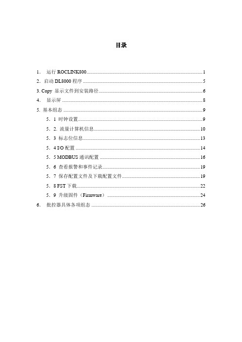
目录1.运行ROCLINK800 (1)2.启动DL8000程序 (5)3. Copy 显示文件到安装路径 (6)4.显示屏 (8)5. 基本组态 (9)5.1 时钟设置 (9)5.2. 流量计算机信息 (10)5.3 标志位信息 (13)5.4 I/O配置 (14)5.5 MODBUS通讯配置 (16)5.6 查看报警和事件记录 (19)5.7 保存配置文件及下载配置文件 (19)5.8 FST下载 (22)5.9 升级固件(Firmware) (24)6.批控器具体各项组态 (26)ROCLINK800使用说明1.运行ROCLINK800在与ROC809在线连接时需注意以下事项:需要更改电脑的语言及区域设置,具体步骤如下:1.从电脑左下角的开始菜单中选择设置—>控制面板;2.在控制面板里选择“区域及语言选项”后出现如下画面:3.在“高级”选项卡中,将语言设置从中文(中国)改为英文(美国),如下图所示。
4.点击“应用”按钮,弹出需要重新启动电脑的对话框,点击Yes,重启电脑之后设置修改成功。
5.连接ROC809到电脑。
6.双击ROCLINK800图标,打开组态软件,显示如下登陆界面:7.鼠标放在“User ID”字母上,单击左键;8.如果使用LOI编程口组态,则点击直接连接后,等ROCLINK800软件右下角的红色“OFF-LINE”标记变为绿色“ON-LINE”后,连接成功。
点击此图标,建立电脑和ROC809的连接9.如果使用以太网口,需要使用交叉网线(即电脑与电脑连接所用网线),建立连接步骤如下:新的DL8000默认IP地址为:IP: 10.0.0.2子网掩码:255.255.255.0网关:10.0.0.1连接前首先确认将电脑IP配置到同一网段,Ping是否能通,然后点击Ethernet Device的属性,如图:检查IP是否为10.0.0.2如果是,可以点击上方的Connect按钮,或者双击Ethernet Device图标,等待连接。
锐普德数控R8010T车床数控系统用户手册

2H
172H
5.5 参数恢复..........................................................................................................................................13
0H
150H
1.1 产品特点............................................................................................................................................2
19H
169H
5.2 系统参数修改..................................................................................................................................12
20H
26H
176H
6.1 绝对坐标显示..................................................................................................................................15
27H
6H
156H
第四章 程序管理方式..................................................9
7H
157H
4 .1 程序管理...........................................................................................................................................9
Barrier 80 产品说明书

物理特性
颜色
灰色
体积固体份(%)* 闪点 黏度
61 ± 2 27oC ± 2 (闭杯)
挥发性有机物含量 光泽ຫໍສະໝຸດ 365 gms/ltr UK-PG6/23(97). Appendix 3 平光
耐水性
优异
耐磨性
很好
耐溶剂性
很好
柔韧性
好
*按照ISO3233:1998(E)标准测定
表面处理
所有表面应当清洁、干燥且无污物,表面应当按照ISO8504进行评估和处理。
1混合使用动力搅拌器将3份体积量的a组分基料搅拌均匀然后边搅拌边往里加入1份体积量的b组分固化剂直至充分混合均匀涂装时需持续动力搅熟化时间30分钟混合后使用寿命2312小时随温度升高而缩短
产品技术参数
Barrier 80 环氧富锌底漆
产品介绍
环氧富锌底漆Barrier 80是一种高锌含量双组分环氧富锌底漆,符合SSPC标准-20油漆中锌粉含量等级2和国际标准 ISO 12944有关锌粉底漆的成分要求。也可以根据客户要求,采用符合ASTM D520标准的II类锌粉定制。 .
根据具体情况可以制定其它配套。
(干膜厚度)
贮存
必须按照国家规定贮存。贮存环境应干燥、阴凉、通风良好并避开热源和火源。包装容器必须保持密闭。
装卸
小心装卸。使用前搅拌均匀。在施工时应持续搅拌以免较重的锌粉颜料产生沉淀。
Barrier 80 (产品说明书)
页2
包装规格
4公升单元:3公升 A组分(基料),采用5公升的容器包装;1公升 B组分(固化剂),采用1公升的容器包装。或 者: 9公升单元:6.75公升 A组分(基料),采用10公升的容器包装;2.25公升 B组分(固化剂),采用3公升的容器包 装
frp80端口使用方法
frp80端口使用方法FRP(Fast Reverse Proxy)是一款高性能的反向代理工具,在实际应用中主要用于内网穿透以及将内网资源通过公网访问。
本文将详细介绍FRP 80端口的使用方法。
1.FRP简介:FRP由fatedier开发,支持TCP、UDP、HTTP、HTTPS协议的代理,可将内网服务部署在公网上,从而实现公网访问。
FRP由Server端和Client端组成,Server端部署在公网服务器上,Client端部署在内网服务器上。
2.安装和配置:3. 配置FRP Server端:4. 配置FRP Client端:5. 启动FRP Server和Client:在公网服务器上运行FRP Server端可执行文件,启动FRP Server监听80端口。
在内网服务器上运行FRP Client端可执行文件,连接到FRP Server。
通过查看日志,检查Server和Client的连接状态是否正常。
6.验证80端口访问:在公网服务器上,使用HTTP/HTTPS请求工具如curl或浏览器,通过FRP Server的公网IP地址和80端口,访问内网服务器上的服务。
如果一切正常,将会获得内网服务的响应内容。
通过调试日志,可以检查请求是否是通过FRP代理正常转发的。
7.高级配置:FRP支持高级配置,可用于实现更复杂的应用场景。
例如,使用frps.ini的`subdomain_host`配置项实现使用子域名访问不同的内网服务;使用frpc.ini的`tcp_mux`配置项开启TCP多路复用以提高性能等。
详细配置可参考FRP官方文档。
总结:FRP提供了一种简单且高性能的解决方案,可以将内网服务通过80端口发布到公网,并实现公网访问。
通过按照上述步骤安装和配置FRP Server和Client,并进行相应的测试和调试,即可成功使用FRP 80端口。
但是需要注意的是,FRP的安装和配置需要具备一定的网络和系统知识,同时要确保公网服务器对外开放了80端口。
frp 80端口 使用方法

frp 80端口使用方法FRP(Fast Reverse Proxy)是一种用于将内网服务映射到公网的工具。
它可以让你在无需公网IP 的情况下访问内网服务,实现穿透内网的功能。
在本篇文章中,我将向您介绍使用FRP工具将内网服务映射到80端口的方法。
首先,确保您已经成功安装了FRP工具。
您可以在FRP的官方网站上找到适用于您操作系统的安装包,并按照官方文档进行安装。
接下来,我们需要对FRP进行配置。
配置文件通常为frps.ini或frpc.ini。
在配置文件中,您需要添加与80端口有关的配置。
对于服务器端(frps.ini),请按照以下步骤进行配置:1. 打开frps.ini文件并找到 [common] 段落。
2. 在 [common] 段落中添加以下配置:```bind_port = 80vhost_http_port = 80```这将允许FRP监听80端口,并将流量转发到您指定的内网服务。
对于客户端(frpc.ini),请按照以下步骤进行配置:1. 打开frpc.ini文件并找到 [common] 段落。
2. 在 [common] 段落中添加以下配置:```[http]type = httplocal_port = 80custom_domains = 你的域名```将 "你的域名" 替换为您想要绑定的域名。
这将指定FRP在公网上将流量转发到您的内网服务。
配置完成后,保存并关闭配置文件。
最后,在命令行或终端中运行FRP,并指定对应的配置文件。
例如,对于服务器端,可以使用以下命令启动FRP:```./frps -c frps.ini```对于客户端,可以使用以下命令启动FRP:```./frpc -c frpc.ini```现在,您已经成功配置了FRP将内网服务映射到80端口。
您可以通过访问您的域名来访问内网服务,并在公网上使用80端口进行通信。
需要注意的是,确保服务器和客户端的防火墙配置允许FRP的流量通过80端口。
Quantum Spark 1600 1800 Hardware Appliances R80.20

型號:V 82、V 83[分類:受保護]Check Point版權聲明Check Point版權聲明©2020Check Point Software Technologies Ltd.版權所有。
本出版物和相關文件受版權保護,並根據分發授權限制其使用、複製、發行和反編譯。
未經Check Point書面授權,不得以任何形式或方式重製本產品或相關文件的任何部分。
儘管CheckPoint已對本出版物作出合理審慎的預防措施,但不擔保內容的錯誤或遺漏。
本出版物和本文所述功能若有更改,恕不另行通知。
有限權利說明:政府機構使用、發行或揭露必須遵循DFARS252.227-7013和FAR52.227-19中技術資料和電腦軟體權利條款中(c)(1)(ii)項的限制。
商標:如需我們的商標清單,請參閱版權頁。
如需相關版權和第三方授權的清單,請參閱第三方版權聲明。
Quantum Spark1600/1800硬體設備R80.20.XX入門指南重要資訊最新的軟體建議您安裝最新的軟體版本,以便將最新功能改良、穩定性修正、安全性增強功能,以及防禦新攻擊與不斷改變的攻擊維持在最新狀態。
認證如需Check Point產品的第三方獨立認證,請參閱Check Point認證頁面。
Check Point1600和1800硬體設備如需更多有關這些硬體設備的資訊,請參閱1600和1800硬體設備首頁。
本文件的最新英文版本在網頁瀏覽器開啟本文件的最新英文版本。
下載本文件PDF格式的最新英文版本。
意見反應Check Point致力於不斷努力改進其文件。
請傳送您的意見來協助我們。
修訂記錄目錄簡介5 Quantum Spark1600/1800硬體設備6裝運箱內容7設定硬體設備8連接纜線9初次部署選項10硬體設備圖表與規格11前面板12 1600硬體設備的前面板12 1800硬體設備的前面板14管理LED15網路LED16背面板18使用「首次設定精靈」19歡迎20 Zero Touch20驗證詳細資料22硬體設備日期與時間設定23硬體設備名稱24安全性原則管理25網際網路連線26區域網路28管理員存取29硬體設備註冊30安全管理伺服器驗證32安全管理伺服器連線33軟體刀鋒啟用35摘要36 Zero Touch雲端服務37 USB磁碟機38健康與安全資訊39支援45簡介感謝您選擇Check Point的網際網路安全套裝產品。
AP80N03D 80A 30V TO-252

1DescriptionThe AP80N03D uses advanced trench technology to provide excellent R DS(ON), low gate charge and operation with gate voltages as low as 4.5V. This device is suitable for use as aBattery protection or in other Switching application.General FeaturesV DS = 30V I D =80 A R DS(ON) < 6m Ω @ V GS =10VApplicationBattery protection Load switchUninterruptible power supplyAbsolute Maximum Ratings (T C =25℃unless otherwise noted)Electrical Characteristics (T J=25℃, unless otherwise noted)23F i g.1 C ontinuous Drain Current vs. TcFig. 3 NormalizedVthvs. TjJTC, Case Temperature (℃)Fig.2Normalized RDSON vs. TjTJ, Junction Temperature (℃)Qg , Gate Charge (nC)Fig .4Gate Charge WaveformSquare Wave Pulse Duration (s) V DS, Drain to Source V oltage (V ) Fig.6 Maximum Safe Operation AreaFig.5 Normalized Transient Impedance T J , Junction Temperature ( ℃)4T d(on)T ron T d(off)T foff V DSV GS10 %IASV GSBV DSSV DDEAS= 12 L x I AS 2 x BVDSS BV DSS V - DDF i g. 8 E AS Wavefo rmF i g . 7 S witching Time Waveform5Package Mechanical DataDimensionsMillimeters Inches Ref.Min.Typ.Max.Min.Typ.Max.A A2B C DE G H LV1V22.1000.660.40 2.500.100.860.600.08300.0260.0160.0980.0040.0340.0246.409.5010.700.3740.4210.0530.0655.906.30L20°6°0.2320.2486.800.2520.2684.47 4.670.1760.1841.09 1.210.0430.0487°1.351.650°6°7°B2 5.18 5.480.2020.216C20.440.580.0170.023D1E15.30REF4.630.1820.209REFDETAIL ATO-252Reel Spectification-TO-252ABBDimensionsMillimeters Inches Ref.Min.Typ.Max.Min.Typ.Max.W E F D0D1P0P1P2A0B0K0T t115.901.657.401.4016.101.857.601.600.6260.0650.2910.0550.6340.0730.2990.0631.40 1.607.9010.4510.600.4110.4170.240.270.0090.0110.0550.0633.90 4.106.900.27110P00.1540.1618.100.3110.3191.90 2.100.0750.0830.100.00440.001.5752.780.10916.001.757.501.501.504.008.002.0010.500.6300.0690.2950.0590.0590.1570.3150.0790.4136.857.002.68 2.880.2700.2760.1050.11339.8040.201.5671.583Attention1,Any and all APM Microelectronics products described or contained herein do not have specificationsthat can handle applications that require extremely high levels of reliability, such as life support systems, aircraft's control systems, or other applications whose failure can be reasonably expected to result inserious physical and/or material damage. Consult with your APM Microelectronics representative nearestyou before using any APM Microelectronics products described or contained herein in such applications.2,APM Microelectronics assumes no responsibility for equipment failures that result from using productsat values that exceed, even momentarily, rated values (such as maximum ratings, operating condition ranges, or other parameters) listed in products specifications of any and all APM Microelectronicsproducts described or contained herein.3, Specifications of any and all APM Microelectronics products described or contained here instipulate the performance, characteristics, and functions of the describ ed products in the independent state, and arenot guarantees of the performance, characteristics, and functions of the described products as mountedin the customer’s products or equipment. To verify symptoms and states that cannot be evaluated in an independent device, the customer should always evaluate and test devices mounted in the customer’s products or equipment.4, APM Microelectronics Semiconductor CO., LTD. strives to supply high quality high reliability products. However, any and all semiconductor products fail with some probability. It is possible that theseprobabilistic failures could give rise to accidents or events that could endanger human lives that couldgive rise to smoke or fire, or that could cause damage to other property. When designing equipment,adopt safety measures so that these kinds of accidents or events cannot occur. Such measures includebut are not limited to protective circuits and error prevention circuits for safe design, redundantdesign,and structural design.5,In the event that any or all APM Microelectronics products(including technical data, services) describedor contained herein are controlled under any of applicable local export control laws and regulations, such products must not be exported without obtaining the export license from the authorities concerned in accordance with the above law.6, No part of this publication may be reproduced or transmitted in any form or by any means,electronic or mechanical, including photocopying and recording, or any information storage or retrieval system, or otherwise, without the prior written permission of APM Microelectronics Semiconductor CO., LTD.7, Information (including circuit diagrams and circuit parameters) herein is for example only; it is not guaranteed for volume production. APM Microelectronics believes information herein is accurate andreliable, but no guarantees are made or implied regarding its use or any infringements of intellectualproperty rights or other rights of third parties.8, Any and all information described or contained herein are subject to change without notice due toproduct/technology improvement,etc. When designing equipment, refer to the "Delivery Specification" forthe APM Microelectronics product that you Intend to use.6。
一.东微Green-MOS(500900V)
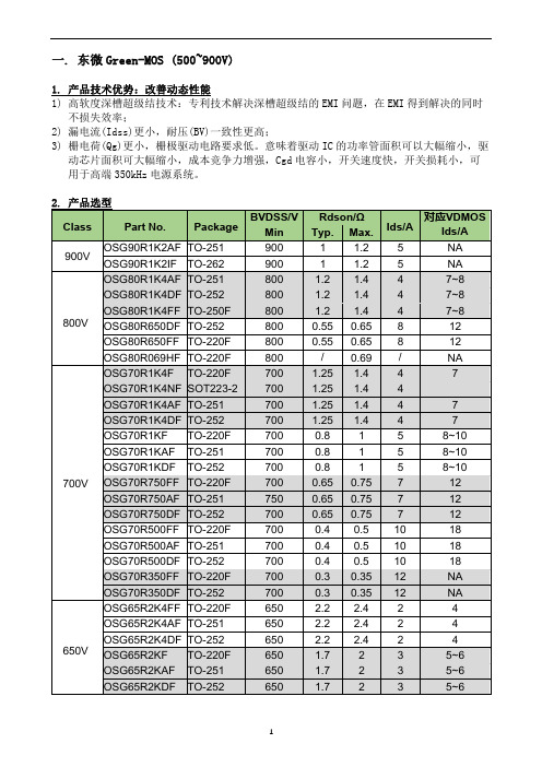
一. 东微Green-MOS (500~900V)1. 产品技术优势:改善动态性能1) 高软度深槽超级结技术:专利技术解决深槽超级结的EMI问题,在EMI得到解决的同时不损失效率;2) 漏电流(Idss)更小,耐压(BV)一致性更高;3) 栅电荷(Qg)更小,栅极驱动电路要求低。
意味着驱动IC的功率管面积可以大幅缩小,驱动芯片面积可大幅缩小,成本竞争力增强,Cgd电容小,开关速度快,开关损耗小,可用于高端350kHz电源系统。
2. 产品选型Class Part No. Package BVDSS/V Rdson/ΩIds/A对应VDMOSIds/A Min Typ.Max.900V OSG90R1K2AF TO-251 900 1 1.2 5 NA OSG90R1K2IF TO-262 900 1 1.2 5 NA800V OSG80R1K4AF TO-251 800 1.2 1.4 47~8OSG80R1K4DF TO-252 800 1.2 1.4 47~8OSG80R1K4FF TO-250F 800 1.2 1.4 47~8OSG80R650DF TO-252 8000.550.658 12 OSG80R650FF TO-220F 800 0.55 0.65 8 12 OSG80R069HF TO-220F 800 / 0.69 / NA700V OSG70R1K4F TO-220F 700 1.25 1.4 47OSG70R1K4NF SOT223-2700 1.25 1.4 4OSG70R1K4AF TO-251 700 1.25 1.4 47OSG70R1K4DF TO-252 700 1.25 1.4 47OSG70R1KF TO-220F 700 0.8 15 8~10 OSG70R1KAF TO-251 700 0.8 15 8~10 OSG70R1KDF TO-252 700 0.8 15 8~10 OSG70R750FF TO-220F 700 0.65 0.75 712OSG70R750AF TO-251 750 0.65 0.75 712OSG70R750DF TO-252 700 0.65 0.75 712OSG70R500FF TO-220F 700 0.4 0.5 10 18 OSG70R500AF TO-251 700 0.4 0.5 10 18 OSG70R500DF TO-252 700 0.4 0.5 10 18 OSG70R350FF TO-220F 700 0.3 0.35 12 NAOSG70R350DF TO-252 700 0.3 0.35 12 NA650V OSG65R2K4FF TO-220F 650 2.2 2.4 24 OSG65R2K4AF TO-251 650 2.2 2.4 24 OSG65R2K4DF TO-252 650 2.2 2.4 24 OSG65R2KF TO-220F 650 1.7 235~6 OSG65R2KAF TO-251 650 1.7 235~6 OSG65R2KDF TO-252 650 1.7 235~6Class Part No. Package BVDSS/V Rdson/ΩIds/A对应VDMOSIds/A Min Typ.Max.650V OSG65R1K4FF TO-220F650 1.21.4 47OSG65R1K4AF TO-251 650 1.21.4 47OSG65R1K4DF TO-252 650 1.21.4 47OSG07N65F TO-220F650 0.9 1 4.5 7~8OSG65R900FF TO-220F650 0.720.9 5 8~10 OSG65R900P TO-220 650 0.720.9 5 8~10 OSG65R900FEF TO-220F650 0.720.9 5 8~10 OSG65R900AF TO-251 650 0.720.9 5 8~10 OSG65R900DF TO-252 650 0.720.9 5 8~10 OSG65R760FF TO-220F650 0.66 0.76 710OSG65R760IF TO-262 650 0.66 0.76 710OSG65R760AF TO-251 650 0.66 0.76 710OSG65R760DF TO-252 650 0.66 0.76 710OSG65R650F TO-220F650 0.550.657.5 11 OSG65R580FF TO-220F650 0.5 0.58 812OSG65R580P TO-220 650 0.5 0.58 812OSG65R580FEF TO-220F650 0.5 0.58 812OSG65R580AF TO-251 650 0.5 0.58 812OSG65R580DF TO-252 650 0.5 0.58 812OSG65R460FZF TO-220F650 0.380.4610 15 OSG65R460DZF TO-252 650 0.380.4610 15 OSG65R380FF TO-220F650 0.33 0.38 11 15~18OSG65R380PF TO-220 650 0.33 0.38 11 15~18OSG65R380KF TO-263 650 0.33 0.38 11 15~18OSG65R380AF TO-251 650 0.35 0.38 11 15~18OSG65R380DF TO-252 650 0.35 0.38 11 15~18OSG65R290PF TO-220 650 0.260.2915 NA OSG65R290FF TO-220F650 0.260.2915 NA OSG65R290KF TO-263 650 0.260.2915 NA OSG65R290AF TO-251 650 0.260.2915 NA OSG65R290DF TO-252 650 0.260.2915 NA OSG65R200PF TO-220 650 0.17 0.2 20 NAOSG65R200FF TO-220F650 0.17 0.2 20 NAOSG65R200HF TO-247 650 0.17 0.2 20 NAOSG65R200KF TO-263 650 0.17 0.2 20 NAOSG65R220PZF TO-220 650 0.188 0.222 20 NAOSG65R220IZF TO-262 650 0.18 0.22 20 NAClass Part No. Package BVDSS/V Rdson/ΩIds/A对应VDMOSIds/A Min Typ. Max.650V OSG65R099FF TO-220F650 0.0920.09938 NA OSG65R099FZF TO-220F650 0.0920.09938 NA OSG65R099HF TO-247 650 0.0920.09938 NA OSG65R099HZF TO-247 650 0.0920.09938 NA OSG65R069HF TO-247 650 0.06 0.06953 NA OSG65R069HZF TO-247 650 0.06 0.06953 NA OSG65R042HF TO-247 650 0.0380.04278 NA OSG65R041HZF TO-247 650 0.0380.04178 NA OSG65R038HZF TO-247 650 0.0350.03880 NA OSG65R035HZF TO-247 650 0.0320.03580 NA600V OSG60R2K8DF TO-252 600 2.5 2.8 1.5 3OSG60R2K2FSF TO-220F600 1.6 2.2 2.5 5~6OSG60R2K2AF TO-251 600 2 2.2 24OSG60R2K2DF TO-252 600 2 2.2 24OSG60R1K8F TO-220F600 1.55 1.8 35~6OSG60R1K8AF TO-251 600 1.55 1.8 35~6OSG60R1K8DF TO-252 600 1.55 1.8 35~6OSG60R1K2F TO-220F600 1 1.2 47OSG60R1K2AF TO-251 600 1 1.2 47OSG60R1K2DF TO-252 600 1 1.2 47OSG60R900F TO-220F600 0.7 0.9 58~10OSG60R900AF TO-251 600 0.7 0.9 58~10OSG60R900DF TO-252 600 0.7 0.9 58~10OSG60R670FF TO-220F600 0.58 0.67 7 10 OSG60R580F TO-220F600 0.5 0.58 812OSG60R580AF TO-251 600 0.5 0.58 812OSG60R580DF TO-252 600 0.5 0.58 812OSG60R380FF TO-220F600 0.33 0.38 11 15~18 OSG60R380IF TO-262 600 0.33 0.38 11 15~18 OSG60R380AF TO-251 600 0.33 0.38 11 15~18 OSG60R380DF TO-252 600 0.33 0.38 11 15~18 OSG60R260FF TO--220F600 0.233 0.266 15 NAOSG60R260DF TO-252 600 0.23 0.26 15 NAOSG60R180FF TO-220F600 0.15 0.18 20 NA OSG60R180HF TO-247 600 0.15 0.18 20 NA OSG60R180KF TO-263 600 0.15 0.18 20 NA OSG60R180PF TO-220 600 0.15 0.18 20 NA OSG60R180IF TO-262 600 0.15 0.18 20 NA OSG60R150FF TO-220F600 0.12 0.15 23 NAOSG60R150HF TO-247 600 0.12 0.15 23 NAOSG60R150PF TO-220 600 0.12 0.15 23 NAClass Part No. Package BVDSS/V Rdson/ΩIds/A 对应VDMOS Ids/A Min Typ.Max.600V OSG60R092FF TO-220F 600 0.08 0.092 40 NA OSG60R092HF TO-247 600 0.088 0.092 40 NA OSG60R070FF TO-220F 600 0.06 0.07 47 NAOSG60R070HF TO-247 600 0.06 0.07 47 NAOSG60R074HZF TO-247 600 0.0660.074 47 NA OSG60R040HF TO-247 600 0.0350.04 78 NA OSG60R041HZF TO-247 600 0.0350.041 78 NA 550VOSG55R580FF TO-220F 550 0.5 0.58 8 12 OSG55R140FF TO-220F 550 0.12 0.14 23 NAOSG55R140RF TO-3P 550 0.12 0.14 23 NA OSG55R074HZF TO-247 550 0.0650.074 47 NA500V OSG50R500F TO-220F 500 0.45 0.5 9 03. 特性说明1) Green-MOS 是世界上首次实现高软度沟槽超级结芯片高压开关过程中的漏极电流更加平滑,波形更软,过冲下,EMI 改善;2) 世界上首次直接对增加能耗的米勒平台进行优化,去掉了无用的平台尾部,降低系统能耗和发热量,系统效率提升0.2~1%,器件温度下降5~15度。
刷中文recovery V880最简单的刷机教程

看到很多新手小白都在问刷机的问题有点小问题就开帖求助导致880区很混乱,一些人都找不到自己想要的东西,虽然远程或者语音教过很多人但是心有余而力不足算了算了我辛苦一点做个教程吧另外提醒一下请自备刷机包有些小白不知道什么刷机包能用的我来发两个我自己(刷机包不用解压直接放SD卡跟目录或者你自己能找到的目录!)用着觉得不错的刷机包(GEN2)的 GEN1的机器(老版橘子)请刷机之后再刷补丁补丁链接/file/bwoaksxg2.2ROM的链接:/thread-1219912-1-1.html老榕的瑞典之春精简优点是稳定据说很省电放进SD卡根目录不用解压2.3ROM的链接:/c0v5zsgycu G大的2.3 我自己用着觉得不错想尝鲜的人可以试试直接下载放进SD卡根目录就好了不用解压好了废话不多说直接开刷首先要下载附件一个是XP的驱动一个是中文recovery 这个recovery是封包成EXE程序直接运行的所以真的很简单请下载下面的附件不知道自己机器是GEN1还是GEN2的请用附件的GEN 测试软件测试(国行和新版橘子一般是GEN2老版橘子是GEN1)测试软件下载GEN测试.apk (7.35 KB)结果如下图XP 驱动地址:/file/e60nn9dv文件名:xp-driver.rarrecovery中文EXE版下载地址:(GEN2)/file/bhb775gg文件名:recovery3.0.2.4_blade_gen2.exe(国行或者最新的橘子用这个)(GEN1)Recovery模式刷机包(ZIP):/file/f3f6e913cb(老版橘子用这个)最近发现很多朋友(基本上是橘子)音量加键小房子加电源键(或者音量加键加电源键)无法进入fastboot刷recovery 要么直接开机要么出现FTM 这个状态下是不能写入recovery的解决方法:大家去这个链接直接按照方法一开机用软件刷recovery 链接:/thread-1534646-1-1.html这个方法需要ROOT 也就是要获得权限具体ROOT方法论坛有也很多大家去多逛逛论坛或者搜索一下就有了——————————————————————————————————————————————分割线————————————————————————————————————————————————下载好之后手机先关机然后音量下键小房子键同时按着再按着开机键大概5秒钟这个时候手机会停在WO界面插上数据线这个时候XP系统的话会提示安装驱动指定驱动为刚才下载的XP驱动就好了WIN7的系统请按这个步骤操作(XP系统的跳过这一段)我的电脑右键管理设备管理器看到里面有个黄色问号的Android设备右键更新驱动然后指定到刚刚下载的XP驱动文件夹开始安装驱动如下图在安装的时候会提示这个界面选择第二个上面的操作完成之后WIN7设备管理器会多出一个设备如下图——————————————————————————————————分割线————————————————————————————————————————————————————————————————————驱动安装好了之后打开recovery的程序下面看截图(其实很简单的 recovery软件会一步步教你的只要仔细看着就没问题)按照提示按任意键下一步按任意键继续下一步这里很重要这是测试你的驱动是否安装正常!(我这个截图是没有认到驱动的。
红外遥控调制编码方式介绍

Inside a TV Remote Control by Marshall Brain 2004/09/26Weng If you are like most Americans, you probably pick up a TV remote control at least once or twice a day. Let's look inside and see how they work. Here is the remote we will be dissecting today:The remote control's job is to wait for you to press a key, and then to translate that key-press into infrared (pronounced "infra-red") light signals that are received by the TV. When you take off the back cover of the control you can see that there is really just 1 part visible: a printed circuit board that contains the electronics and the battery contacts.The components that you see here are typical for most remotes. You can see an integrated circuit (also known as a chip) labeled "TA11835". The chip is packaged in what is known as an 18 pin Dual Inline Package, or a DIP. To the right of the chip you can see a diode, a transistor (black, with three leads), a resonator (yellow), two resistors (green) and a capacitor (dark blue). Next to the battery contacts there is a resistor (green) and a capacitor (tan disk). In this circuit, the chip can detect when a key is pressed. It then translates the key into a sequence something like morse code, with a different sequence for each different key. The chip sends that signal out to the transistor to amplify the signal and make it stronger.The Circuit BoardWhen you unscrew the circuit board and take it out, you can see that the circuit board is a thin piece of fiber glass that has thin copper "wires" etched onto its surface. Electronic parts are assembled on printed circuit boards because they are easy to mass produce and assemble. In the same way that it is relatively inexpensive to print ink onto a sheet of paper, it is inexensive to "print" copper wires onto a sheet of fiber glass. It is also easy to have a machine drop the parts (the chips, transistors, etc.) onto the sheet of fiberglass and then solder them on to connect them to the copper wires.When you look at the board, you can see a set of contact points for the buttons. The buttons themselves are made of a thin rubbery sheet. For each button there is a black conductive disk. When the disk touches the contacts on the printed circuit board, it connects them and the chip can sense that connection.At the end of the circuit board there is an infrared LED, or Light Emitting Diode. You can think of an LED as a small light bulb. Many LEDs produce visible light, but a remote's LED produces infrared light that is invisible to the human eye. It is not invisible to all eyes, however. For example, if you have a camcorder it can see the infrared light. Point your remote at the camera and push a button. You will be able to see the infrared light flashing in the viewfinder. The receptor in the TV is able to see infrared light as well.So the basic operation of the remote goes like this: You press a button. When you do that youcomplete a specific connection. The chip senses that connection and knows what button you pressed. It produces a morse-code-line signal specific to that button. The transistors amplify the signal and send them to the LED, which translates the signal into infrared light. The sensor in the TV can see the infrared light and "seeing" the signal reacts appropriately.LinksGeneral:∙How Television WorksTechnical:∙Decoding IR Remote Controls∙ A Serial Infrared Remote Control∙IR remote control computer interfacing∙Remote Infrared Control∙Innotech Systems, Inc. - manufacturer紅外遙控調製編碼方式介紹數位小屋在大多數的遙控傳輸系統中,只有少量的資料被傳送到設備。
r580显卡
r580显卡R580显卡,是由AMD(Advanced Micro Devices)公司推出的一款中高端显卡产品。
它采用AMD的Polaris架构,并且是Radeon RX 500系列显卡中的一员。
R580显卡采用了14nm工艺制造,拥有2304个流处理器(SP)和144个纹理单元(TMU),并配备了8GB GDDR5显存。
相对于前一代Radeon RX 480显卡来说,R580在性能方面有所提升,虽然架构上没有太多的改变,但是通过提高核心频率和显存频率,使得性能有了一定的提升。
首先,R580显卡在游戏性能方面表现出色。
它在许多现代游戏中能够提供流畅的高画质体验。
例如,在《绝地求生》和《巫师3:狂猎》等大型游戏中,R580显卡能够以较高的帧率呈现出出色的画面效果。
而且,配备8GB GDDR5显存,可以更好地支持高分辨率游戏和多屏幕游戏。
其次,R580显卡在性能与功耗上取得了一个比较好的平衡。
通过优化的Polaris架构和14nm工艺,R580在保持较高性能的同时,也能够控制功耗,提供较低的发热量。
这对于使用者来说非常重要,因为它意味着可以在相对较小的散热系统上使用R580显卡,而不用担心过热的问题。
最后,R580显卡还支持AMD的Freesync技术,这是一项专为解决游戏卡顿和撕裂现象而设计的技术。
通过与兼容的显示器结合,Freesync技术可以自动调整显卡的输出频率,以匹配显示器的刷新率,从而实现更流畅和更清晰的游戏画面。
总结一下,R580显卡作为一款中高端产品,在游戏性能、功耗和特色功能方面都表现出了良好的性能。
无论是对于游戏爱好者还是对于专业用户来说,R580显卡都是一个值得考虑的选择。
frp 80端口 使用方法

使用frp实现80端口转发什么是frp?frp是一款高性能的反向代理工具,它可以帮助我们实现内网穿透,将内网服务暴露到公网上。
frp支持TCP、UDP和HTTP协议的转发,可以方便地实现端口转发、域名转发等功能。
frp的优势1.简单易用:frp提供了简洁的配置文件,只需简单配置即可使用。
2.高性能:frp采用了高性能的网络通信库,能够处理大量的并发连接。
3.安全可靠:frp支持SSL/TLS加密传输,保障数据的安全性。
4.跨平台支持:frp支持Windows、Linux、Mac等多个操作系统。
frp的工作原理frp的工作原理是通过客户端与服务端之间建立一个可靠的通信通道,实现数据的转发。
客户端将内网服务端口映射到公网上,当外部用户访问公网IP和端口时,frp会将数据转发到内网服务上。
frp的安装和配置1.下载frp首先,我们需要下载frp的客户端和服务端程序。
可以在frp的官方网站()上找到最新的版本。
2.配置frp服务端在frp的安装目录下,找到frps.ini文件并进行配置。
以下是一个示例配置:[common]bind_port = 7000这里的bind_port是frp服务端监听的端口,可以根据实际需要进行修改。
3.配置frp客户端在frp的安装目录下,找到frpc.ini文件并进行配置。
以下是一个示例配置:[common]server_addr = your_server_ipserver_port = 7000[web]type = httplocal_ip = 127.0.0.1local_port = 80remote_port = 8080这里的server_addr是frp服务端的IP地址,server_port是frp服务端的监听端口。
web是一个自定义的服务名称,type是服务类型,local_ip和local_port是内网服务的IP和端口,remote_port是公网访问的端口。
(完整word)80x86指令详解

80x86指令系统,指令按功能可分为以下七个部分.(1) 数据传送指令.(2) 算术运算指令。
(3) 逻辑运算指令。
(4)串操作指令。
(5)控制转移指令。
(6)处理器控制指令。
(7)保护方式指令.1、数据传送指令数据传送指令包括:通用数据传送指令、地址传送指令、标志寄存器传送指令、符号扩展指令、扩展传送指令等.一、通用数据传送指令1 传送指令传送指令是使用最频繁的指令,格式:MOV DEST,SRC功能:把一个字节,字或双字从源操作数SRC传送至目的操作数DEST.传送指令允许的数据流方向见图3 11。
图 3.11 传送指令数据流由上图可知,数据允许流动方向为:通用寄存器之间、通用寄存器和存储器之间、通用寄存器和段寄存器之间、段寄存器和存储器之间,另外还允许立即数传送至通用寄存器或存储器。
但在上述传送过程中,段寄存器CS的值不能用传送指令改变。
例 3.12CPU内部寄存器之间的数据传送。
MOV AL,DH ;AL←DH(8位)MOV DS,AX ;DS←AX(16位)MOV EAX,ESI ;EAX←ESI(32位)例 3.13CPU内部寄存器和存储器之间的数据传送。
MOV [BX],AX ;间接寻址(16位)MOV EAX,[EBX+ESI];基址变址寻址(32位)MOV AL,BLOCK ;BLOCK为变量名,直接寻址(8位)例 3。
14立即数送通用寄存器、存储器。
MOV EAX,12345678H ;EAX←12345678H(32位)MOV [BX],12H ;间接寻址(8位)MOV AX,1234H;AX←1234H(16位)使用该指令应注意以下问题:·源和目的操作数不允许同时为存储器操作数;·源和目的操作数数据类型必须一致;·源和目的操作数不允许同时为段寄存器;·目的操作数不允许为CS和立即数;·当源操作数为立即数时,目的操作数不允许为段寄存器;·传送操作不影响标志位。
Millipore Mini-Reservoir RC800 用户指南说明书

MINI-RESERVOIRRC800User GuideNoticeThe information in this document is subject to change withoutnotice and should not be construed as a commitment by Millipore Corporation. Millipore Corporation assumes no responsibility for any errors that may appear in this document. This manual isbelieved to be complete and accurate at the time of publication. In no event shall Millipore Corporation be liable for incidental or consequential damages in connection with or arising from the use of this manual.© 2004 Millipore Corporation. All rights reserved.Millipore and Amicon are registered trademarks of Millipore Corporation.Delrin is a registered trademark of E.I. du Pont de Nemours.99137, Rev. J, 09/04Contents Introduction (1)Chemical and Temperature Resistance (1)Sterilization (1)Diagram of Mini-Reservoir RC800 Components (2)Setup (3)Diagram of Inlet/Outlet Fitting Components (3)Operation (4)Shutdown (4)Cleaning and Maintenance (4)System Disassembly (4)System Reassembly (4)Ordering Information (5)Specifications (6)Materials of Construction (6)Technical Assistance (6)Standard Warranty (7)IntroductionThis 800 mL auxiliary reservoir (product no. 6028) increases the volume capacity of Millipore ultrafiltration cells. When pressur-ized from an external gas source, RC800 automatically replen-ishes liquid in the cell’s built-in reservoir during filtration (due to the pressure differential between the two containers). With RC800 attached, volumes exceeding normal cell capacity can be processed unattended. The reservoir may also be used to store dialysate during diafiltration or dialysis.Chemical and Temperature ResistanceDO NOT use reservoir with alcohols, strong acids, oxidizing agents, strong bases or organic solvents (esters, ketones, aro-matic and chlorinated hydrocarbons). DO NOT subject unit to temperatures over 100 °F (38 °C).SterilizationUse standard sterilizing gas mixtures or a 5% formalin solution. The RC800 reservoir is not autoclavable. DO NOT use alcohol. Diagram of Mini-Reservoir RC800 ComponentsLetter DescriptionA Top capB Tubing, 1/4” OD polyethylene, 2 × 4 ft.C Liquid outlet fittingD Gas inlet fittingE Pressure relief valve assemblyF O-ring (relief valve)G Recessed portH O-ring (reservoir sleeve)I Tubing, 1/4” OD polyethylene, 1 × 4 3/4 in.J Reservoir sleeveK Bottom capL Strap assemblyMini-Reservoir RC800 User Guide3 Setup1.Connect an appropriate length of supplied tubing to gas inletfitting on the reservoir top cap (marked “G”) as follows:a.Unscrew hexagonal nut and remove the O-ring.b.Slide nut, grab ring, spacer (countersunk side towardgrab ring), and O-ring onto tubing. Leave no more than½” (13mm) of tubing beyond grab ring.c.Insert exposed tubing into reservoir fitting; hand tightennut.d.Connect free end of tubing to fitting of an external gassource.2.Repeat step 1 to connect tubing to liquid outlet fitting on thereservoir top cap (marked “L”). Connect free end of thistubing to ultrafiltration cell.3.Remove pressure-relief valve assembly from top cap. Addliquid to reservoir sleeve; then replace valve assembly,making sure O-ring is in place. Hand tighten.Diagram of Inlet/Outlet Fitting ComponentsLetter DescriptionA Hexagonal nutB Grab ringC SpacerD O-ring OperationTurn on gas and slowly pressurize reservoir. Check connections for leaks, then increase pressure as desired. Liquid will flow continuously from reservoir into cell until the pressures in the two containers equalize.CAUTION:DO NOT operate reservoir at pressures over 75 psi(5.2 bar).ShutdownTurn off gas supply to reservoir. To vent system, turn upper portion of pressure relief valve.Cleaning and MaintenanceIn normal use, this unit should not be disassembled. To add buffer or introduce cleaning solutions, remove the pressure relief valve assembly and add liquid through the recessed port.If disassembly is required, the procedures below must be strictly followed.System Disassembly1.Vent system pressure and disconnect gas and liquid tubing.2.Remove pressure-relief valve assembly.3.Remove reservoir assembly from trapezoidal strap assembly.4.Pry top and bottom caps from reservoir sleeve, using toolprovided.5.Remove O-rings from top and bottom caps.6.Wash all parts with soap and water.System Reassembly1.Inspect O-rings for cuts or wear; if necessary, replace anydamaged ones with spares.2.Lubricate O-rings with glycerin or water and reposition themon top and bottom caps.3.Push top and bottom caps into reservoir sleeve until properlyseated, then slide reservoir assembly into strap assembly.Mini-Reservoir RC800 User Guide5 Ordering InformationThis section lists the catalogue numbers for the Mini-Reservoir RC800 and its replacement and accessory parts. See the Techni-cal Assistance section for information about contacting Milli-pore.Replacement Parts Catalogue No.Qty Top cap209731 Reservoir sleeve209611 Bottom cap209591O-ring (reservoir sleeve)2239S4 Tubing 1/4" OD polyethylene XXPE 000 1010 ft. Pressure relief valve assembly10021021O-ring (relief valve)2015B2Gas inlet/liquid outlet fitting, elbow,420130100231/4 × 1/4" NPTStrap assembly153241 Cap removal tool211431 Accessory Equipment Catalogue No.Qty CDS10 Concentration/Dialysis Selector60031 For instant switching from concentrationto rapid dialysis (Diafiltration).MF2 Push-Button Manifold60151 For operation of multiple cells orreservoirs; individually valved.TA1 Tubing Adapter Kit60221 Adapts plastic tubing to 1/8" or 1/4" maleor female gas fittings. SpecificationsCapacity: 800 mLHoldup volume: 4 mLMaximum operating pressure: 75 psi (5.2 bar)Dimensions of reservoir assembly:4 3/4 in. diameter ×5 1/4 in. high (12 cm × 13.3 cm)Weight (including strap): 3.7 lbs (1.7 kg)Materials of ConstructionReservoir sleeve: acrylicTop and bottom caps: Delrin® resinTubing fittings: nylonTubing: polyethyleneO-rings (red): silicone rubberO-rings (black): Buna-N nitrile rubberCompliance with the Pressure Equipment Directive, 97/23/ECMillipore Corporation certifies that this product complies with the European Pressure Equipment Directive, 97/23/EC of 29 May 1997.This product is classified under Article 3 § 3 of the Pressure Equipment Directive. It has been designed and manufactured in accordance with sound engineering practice to ensure safe use. The product is accompanied by user instructions and bears markings to permit identification of Millipore Corporation as the manufacturer or authorized representative of this product within the European Community.In compliance with Article 3 § 3 of the Pressure Equipment Directive, this product does not bear the CE mark.Mini-Reservoir RC800 User Guide7 Technical AsssistanceFor more information, contact the Millipore office nearest you. In the U.S., call 1-800-MILLIPORE (1-800-645-5476). Outside the U.S., see your Millipore catalogue for the phone number of the office nearest you or go to our web site at/offices for up-to-date worldwide contact information. You can also visit the tech service page on our web site at /techservice.Standard WarrantyMillipore Corporation ("Millipore") warrants its products will meet their applicable published specifications when used in accordance with their applicable instructions for a period of one year from shipment of the products. MILLIPORE MAKES NO OTHER WARRANTY, EXPRESSED OR IMPLIED. THERE IS NO WARRANTY OF MERCHANTABILITY OR FITNESS FOR A PARTICULAR PURPOSE. The warranty provided herein andthe data, specifications and descriptions of Millipore products appearing in Millipore's published catalogues and product literature may not be altered except by express written agree-ment signed by an officer of Millipore. Representations, oral or written, which are inconsistent with this warranty or such publications are not authorized and if given, should not be relied upon.In the event of a breach of the foregoing warranty, Millipore's sole obligation shall be to repair or replace, at its option, the applicable product or part thereof, provided the customer notifies Millipore promptly of any such breach. If after exercis-ing reasonable efforts, Millipore is unable to repair or replace the product or part, then Millipore shall refund to the customer all monies paid for such applicable product or part. MILLI-PORE SHALL NOT BE LIABLE FOR CONSEQUENTIAL, INCI-DENTAL, SPECIAL OR ANY OTHER INDIRECT DAMAGES RESULTING FROM ECONOMIC LOSS OR PROPERTY DAM-AGE SUSTAINED BY ANY CUSTOMER FROM THE USE OF ITS PRODUCTS.。
rp80说明
RP80操作简要说明
1、开机
2、显示>BASE MUTE (显示BASE标示为单工收发)
CH1
3、按右下角的确认键“←/”,显示REPEA TER(中转模式)
4、按↓键到MUTE前面,再按确认键显示为MONI,这时机器喇叭就会响了。
5、按↓三次到显示MODE CHANG
6、再按确认键显示PROGRAM,再按↓到显示INDIVIDUAL
7、再按确认键,进入频率设置,选择RX 439.60000mhz,再按↓后输入RX频率
8、然后再按↓修改TX频率。
9、再按↓选择TONE,然后选择TONE A,按确认键,选择TCCSS,然后修改RX 88.5亚音和TX88.5亚音。
10、按↓按到最下面显示EXIT,按确认键退回到上一级菜单,依次退到主菜单。
另外:如直接修改频率,开机后连续按↓到MODE CHANG,即可按上面方法修改频率。
当然只要回了上面的内容,增加频道、修改步进间隔、加密、调整LCD对比度等你自然就会了。
MMF80R900P
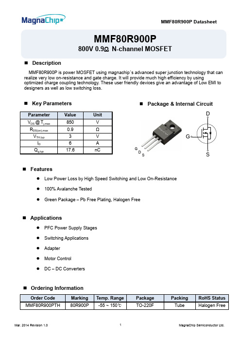
MMF80R900P800V 0.9Ω N-channel MOSFET⏹ DescriptionMMF80R900P is power MOSFET using magnachip ’s advanced super junction technology that can realize very low on-resistance and gate charge. It will provide much high efficiency by usingoptimized charge coupling technology. These user friendly devices give an advantage of Low EMI to designers as well as low switching loss.⏹ Features● Low Power Loss by High Speed Switching and Low On-Resistance ● 100% Avalanche Tested ● Green Package – Pb Free Plating, Halogen Free⏹ Key Parameters⏹ Ordering Information⏹ Applications● PFC Power Supply Stages● Switching Applications● Adapter● Motor Control● DC – DC ConvertersD GS⏹ Package & Internal Circuit⏹Absolute Maximum Rating (Tc=25℃unless otherwise specified)P j,max2) I SD≤I D, V DS peak ≤V(BR)DSS⏹Thermal Characteristics⏹Static Characteristics (T c=25℃unless otherwise specified)⏹Dynamic Characteristics (T c=25℃unless otherwise specified)o(er) OSS DS(BR)DSSReverse Diode Characteristics (T c=25℃unless otherwise specified)Characteristic GraphTest Circuit10VSame type as DUTV gs V DSV gsI V DSV gs10VV GSChargeV DSV DDV DS(t)ASFig15-1. Gate charge measurement circuit Fig15-2. Gate charge waveformFig16-1. Diode reverse recovery test circuitFig16-1. Diode reverse recovery test waveformFig17-1. Switching time test circuit for resistive loadFig17-2. Switching time waveformFig18-1. Unclamped inductive load test circuit Fig18-2. Unclamped inductive waveformPhysical Dimension3 Leads, TO-220FDimensions are in millimeters unless otherwise specifiedDISCLAIMER:The Products are not designed for use in hostile environments, including, without limitation, aircraft, nuclear power generation, medical appliances, and devices or systems in which malfunction of any Product can reasonably be expected to result in a personal injury. Seller’s customers using or selling Seller’s products for use in such applications do so at their own risk and agree to fully defend and indemnify Seller.MagnaChip reserves the right to change the specifications and circuitry without notice at any time. MagnaChip does not consider responsibility for use of any circuitry other than circuitry entirely included in a MagnaChip product. is a registered trademark of MagnaChip Semiconductor Ltd.。
- 1、下载文档前请自行甄别文档内容的完整性,平台不提供额外的编辑、内容补充、找答案等附加服务。
- 2、"仅部分预览"的文档,不可在线预览部分如存在完整性等问题,可反馈申请退款(可完整预览的文档不适用该条件!)。
- 3、如文档侵犯您的权益,请联系客服反馈,我们会尽快为您处理(人工客服工作时间:9:00-18:30)。
副本编号:广济药业(孟州)有限公司部门:质量监督科题目:饲料添加剂维生素B2(核黄素)流动性微粒 (维生素B280%喷干微粒)共8页第1页文件编码:SMP-6-501新订:01替代:起草:部门审查:QA审查:批准:执行日期:2009-03-10变更记载:修订号:批准:执行日期:变更原因及目的:文件副本分发明细质量监督科01检测中心02正本:质量监督科副本编号:01-02文本编号SMP-6-501 版本号01 生效日期2009/03/10 第 2 页共 8 页饲料添加剂维生素B2(核黄素)流动性微粒(维生素B280%喷干微粒)标准编号:Q/MG.C01-2009 1主题内容与适用范围本标准规定了饲料添加剂维生素B2(又名核黄素)流动性微粒(维生素B280%喷干微粒)产品的要求、试验方法、标签、包装、贮存及运输。
本标准适用于以生物发酵法或化学合成法生产的维生素B2加入适量符合饲料卫生标准的淀粉、粘合剂及香料,经喷雾干燥而成的饲料添加剂维生素B2流动性微粒。
2 引用标准GB/T18632-20023 技术要求3.1 性状本品为黄色至棕黄色高流动性、无静电的均匀微粒。
本品味微苦,易吸潮,溶液易变质,在碱溶液中或遇光变质更快。
3.2 饲料添加剂维生素B2流动性微粒应符合表1的要求。
表1项目指标标示量含维生素B2为80%含量(以C17H20N4O6计,占标示量的百分比)% 97.0~105.0含量(以C17H20N4O6计) % 77.6~84粒度最少90%通过0.28㎜标准筛干燥失重% ≤3.03.3 安全卫生指标饲料添加剂维生素B2流动性微粒应符合表2的安全卫生指标。
表2项目指标炽灼残渣/% 5有机挥发性杂质允许量(每千克产品中)/mg苯 2 三氯甲烷60 1,4-二氧六环380 二氯甲烷600文本编号SMP-6-501 版本号01 生效日期2009/03/10 第 3 页共 8 页三氯乙烯804 试验方法本标准中所用普通试剂均为分析纯,试验用水均为符合GB/T 6682中规定的三级水。
色谱分析中所用试剂为优级纯,试验用水均为符合GB/T 6682中规定的一级水。
4.1 维生素B鉴别试验24.1.1 试剂、溶液4.1.1.1 氢氧化钠溶液:4%。
4.1.1.2 盐酸溶液:4%。
4.1.1.3 连二亚硫酸钠。
4.1.2 鉴别方法取试验溶液(4.2.4.1)于白色容量瓶中,溶液在透射光下显淡黄绿色,并有黄绿色荧光,将试液分成两份,一份中加氢氧化钠溶液或盐酸溶液,荧光即消失;另一份中加少许连二亚硫酸钠结晶,摇匀后黄色即消失,荧光亦消失。
4.2 维生素B含量的测定(高效液相色谱法)24.2.1 方法提要将试样制备成试验溶液,注入高效液相色谱仪进行分离,用紫外检测器测定,按外标法(峰面积)计算试样中维生素B的含量。
24.2.2 试剂、试液4.2.2.1 甲醇。
4.2.2.2 冰乙酸溶液:0.25%。
4.2.2.3 维生素B标准品:纯度为大于99.5%。
2标准品4.2.2.4 标准溶液制备(避光操作):称取经105℃干燥2h的维生素B240mg(精确至0.0001g)于100ml烧杯中,加5 ml冰乙酸和75ml水,缓缓加热至完全溶解,加50ml水稀释,放冷,移人250ml棕色容量瓶,用水定容,摇匀。
过滤,弃去最初滤液,取续滤液15ml于100 ml棕色容量瓶中,用流动相(4.2.4.2)定容,摇匀。
该溶液浓度为24μg/ml。
4℃冰箱中保存,可在一个月内使用。
4.2.3 仪器、设备4.2.3.1 实验室常用仪器没备。
4.2.3.2 液相色谱仪,带紫外检测器。
4.2.3.3 微孔滤膜,孔径0.45μm。
4.2.3.4 超声波水浴。
文本编号SMP-6-501 版本号01 生效日期2009/03/10 第 4 页共 8 页4.2.4 操作步骤4.2.4.1 试验溶液制备(避光操作)称取试样50㎎(精确至0.0001g)于250ml烧杯中,加5ml冰乙酸与90ml水,缓缓加热至完全溶解,加50ml水稀释,放冷,移入250ml棕色容量瓶,用水定容,摇匀。
过滤,弃去最初滤液,取续滤液15ml于100ml棕色容量瓶中,用流动相(4.2.4.2)定容,摇匀。
4.2.4.2 高效液相色谱条件色谱柱:内径4.6㎜,柱长250mm,填料为C18粒度5 μm的不锈钢柱。
检测器:紫外检测器,检测波长269 nm。
流动相:甲醇:冰乙酸溶液(0.25%)=28:72。
流量:1.0 ml/min。
进样量:20μL。
4.2.4.3 测定取标准溶液(4.2.2.4)和试验溶液(4.2.4.1),经微孔滤膜过滤后,分别进样20μL,按外标法用峰面积计算试样中维生素B2的含量。
4.2.5 计算和结果的表述以质量分数表示维生素B2的含量(X1),按式(1)计算:X 1(%)=C×V×Vst×Pim×Vi×Pst×1000×100% (1)式中:C——维生素B2标准溶液的浓度,μg/mL。
V——试验溶液中样品总稀释体积,mL。
Vst ——维生素B2标准溶液的进样体积,μL。
Pi ——试验溶液中维生素B2峰面积。
m——按干品计试样的质量,mg。
Vi——试验溶液的进样体积,μL。
Pst ——标准溶液中维生素B2的峰面积。
1000——换算系数。
计算结果表示至小数点后一位。
4.2.6 允许差取平行测定结果的算术平均值为测定结果,两次平行测定的绝对差值不得大于2.0%。
4.3 粒度的测定4.3.1 方法提要用规定孔径的标准筛筛动试样,称量通过标准筛的试样质量,计算其在试样中的质文本编号SMP-6-501 版本号01 生效日期2009/03/10 第 5 页共 8 页量分数。
4.3.2 仪器、设备4.3.2.1 标准筛:孔径0.28mm。
4.3.2.2 台式天平;100g。
4.3.3 操作步骤称取试样20g于已迭放孔径0.28 mm的标准筛,振动标准筛5 min,收取并称量通过孔径0.28mm标准筛的试样质量。
4.3.4 计算和结果的表述以质量分数表示的试样粒度(X2)按式(2)计算:X 2(%)=m1m×100% (2)式中:m1——通过孔径0.28mm标准筛的试样质量,g;m——试样质量,g。
计算结果表示至整数位。
4.3.5 允许差取平行测定结果的算术平均值为测定结果,两次平行测定的绝对差值不得大于5%。
4.4 干燥失重的测定4.4.1 测定方法称取样品约1.0g(准确至0.0002g),置于已在105℃烘箱中干燥至恒重的称量瓶中,放置105℃烘箱中,打开称量瓶瓶盖,干燥至恒重,取出放入干燥器(有硅胶干燥剂)中,放冷至室温,称重。
同一样品进行两次平行测定。
4.4.2 计算和结果的表示干燥失重X3(以质量百分数表示)按式(3)计算:X 3=G1-G2G×100% (3)式中:G1——干燥前的样品加称量瓶质量,g;G2——干燥后的样品加称量瓶质量,g;G——所称样品质量,g。
4.4.3允许差取两次平行测定的算术平均值为测定结果,两次平行测定的绝对差值不得大于0.3%。
4.4.4结果的表述计算结果表示至小数点后一位。
4.5 炽灼残渣文本编号SMP-6-501 版本号01 生效日期2009/03/10 第 6 页共 8 页4.5.1测定方法称取样品1g(准确至0.01g).置于已在700~800℃灼烧至恒重的石英坩埚中,用小火缓缓加热至完全炭化,放冷后,加硫酸0.5~lml使湿润,低温加热至硫酸蒸气除尽后,移入马福炉中,在700~800℃下灼烧至恒重。
同一样品做两次平行测定。
4.5.2 计算和结果的表示炽灼残渣X3(以重量百分数表示)按式(4)计算:X 4=m1-m2m×100% (4)式中:m1——坩埚加残渣质量,g;m2——坩埚质量,g;m——样品质量,g。
4.5.3 允许差取平行测定结果的算术平均值为测定结果,两次平行测定的绝对差值应不得过0.2%。
4.5.4 结果的表述计算结果表示为整数。
4.6 有机挥发性杂质残留的测定(气相色谱法)4.6.1 方法提要用水提取试样中的微量有机挥发性杂质,提取液注入气相色谱仪分离,用氢火焰检测器检测,对试验溶液与标准溶液的各组分相应色谱峰面积进行比较。
4.6.2 试剂、溶液4.6.2.1 苯。
4.6.2.2 三氯甲烷。
4.6.2.3 1,4-二氧六环。
4.6.2.4 二氯甲烷。
4.6.2.5 三氯乙烯。
4.6.2.6 标准溶液的制备分别移取0.4μL苯、6μL三氯甲烷、38μL 1,4-二氧六环、60μL二氯甲烷、8μL 三氯乙烯于已加入950ml水的1000ml容量瓶中加塞,振摇10min,加水至刻度,摇匀。
该溶液浓度为:0.4μg/ml苯、6μg/ml三氯甲烷、38μg/ml 1,4-二氧六环、60μg/ml 二氯甲烷、8μg/ml三氯乙烯。
该溶液要当天制备。
4.6.3 仪器、设备4.6.3.1 实验室常用仪器设备。
4.6.3.2 气相色谱仪,带氢火焰检测器(FID)。
文本编号SMP-6-501 版本号01 生效日期2009/03/10 第 7 页共 8 页4.6.4 操作步骤4.6.4.1 试验溶液制备称取试样250㎎(精确至0.0001g)于10ml离心试管中,加水5.0ml,于超声波水浴上溶解10min,离心,取上清溶液过滤后为试验溶液。
4.6.4.2 气相色谱条件色谱柱:柱长2m,填料GDX-101高分子多孔微球的不锈钢柱。
检测器:FID。
汽化室温度:210℃。
柱温:120℃。
检测器温度:240℃。
载气:氦气,45ml/min。
空气:400 ml/min。
氢气:50 ml/min。
4.6.4.3 气相色谱仪系统性能试验取标准溶液(4.6.2.6)2μL注入气相色谱仪,记录色谱图。
各组分应能检出,分离度应大于1.5。
4.6.4.4 测定分别取标准溶液(4.6.2.6)4μL、经过滤的试验溶液(4.6.4.1)8μL,注入气相色谱仪,记录色谱图。
4.6.5结果的表述试验溶液中的三氯甲烷、1,4-二氧六环、二氯甲烷、三氯乙烯的色谱峰面积不得超过标准溶液中相应的色谱峰面积,苯的色谱峰面积不得超过标准溶液中相应的色谱峰面积的二分之一。
5 检验规则5.1 本标准规定的所有项目为出厂检验项目。
本产品应由我公司质量检验部门进行取样检验。
5.2 我公司保证所有出厂的该产品都符合本标准的要求,并附有一定格式的质量证明书。
5.3 使用单位有权按照本标准的验收规则和试验方法对所有收到的产品进行验收。
5.4 每批产品的质量规定不得超过1吨。
5.5 按我公司《采样办法》进行采样。
5.6 如果在检验中有一项指标不符合标准时,应扩大抽样范围重新抽样检验。
