CISCO三层交换机配置实例
CISCO三层交换机二层交换机配置VLAN的实例精修订
C I S C O三层交换机二层交换机配置V L A N的实例SANY标准化小组 #QS8QHH-HHGX8Q8-GNHHJ8-HHMHGN#CISCO三层交换机+二层交换机配置VLAN的实例Cisco的VLAN实现通常是以端口为中心的。
与节点相连的端口将确定它所驻留的VLAN。
将端口分配给VLAN的方式有两种,分别是静态的和动态的.形成静态VLAN的过程是将端口强制性地分配给VLAN的过程。
即我们先在VTP(VLANTrunkingProtocol)Server上建立VLAN,然后将每个端口分配给相应的VLAN的过程。
这是我们创建VLAN最常用的方法。
动态VLAN形成很简单,由端口决定自己属于哪个VLAN。
即我们先建立一个VMPS (VLANMembershipPolicyServer)VLAN管理策略服务器,里面包含一个文本文件,文件中存有与VLAN映射的MAC地址表。
交换机根据这个映射表决定将端口分配给何种VLAN。
这种方法有很大的优势,但是创建数据库是一项非常艰苦而且非常繁琐的工作。
下面以实例说明如何在一个典型的快速以太局域网中实现VLAN。
所谓典型的局域网就是指由一台具备三层交换功能的核心交换机接几台分支交换机(不一定具备三层交换能力)。
我们假设核心交换机名称为:COM;分支交换机分别为:PAR1、PAR2、PAR3……,分别通过Port1的光线模块与核心交换机相连;并且假设VLAN名称分别为COUNTER、MARKET、MANAGING……。
1、设置VTPDOMAIN:称为管理域。
交换VTP更新信息的所有交换机必须配置为相同的管理域。
如果所有的交换机都以中继线相连,那么只要在核心交换机上设置一个管理域,网络上所有的交换机都加入该域,这样管理域里所有的交换机就能够了解彼此的VLAN 列表。
COM#vlandatabase进入VLAN配置模式COM(vlan)#vtpdomainCOM设置VTP管理域名称COMCOM(vlan)#vtpserver设置交换机为服务器模式PAR1#vlandatabase进入VLAN配置模式PAR1(vlan)#vtpdomainCOM设置VTP管理域名称COMPAR1(vlan)#vtpClient设置交换机为客户端模式PAR2#vlandatabase进入VLAN配置模式PAR2(vlan)#vtpdomainCOM设置VTP管理域名称COMPAR2(vlan)#vtpClient设置交换机为客户端模式PAR3#vlandatabase进入VLAN配置模式PAR3(vlan)#vtpdomainCOM设置VTP管理域名称COMPAR3(vlan)#vtpClient设置交换机为客户端模式注意:这里设置交换机为Server模式是指允许在本交换机上创建、修改、删除VLAN 及其他一些对整个VTP域的配置参数,同步本VTP域中其他交换机传递来的最新的VLAN信息;Client模式是指本交换机不能创建、删除、修改VLAN配置,也不能在NVRAM中存储VLAN配置,但可以同步由本VTP域中其他交换机传递来的VLAN信息。
cisco典型三层交换机VLAN配置

cisco典型三层交换机VLAN配置所谓典型局域网就是指由一台具备三层交换功能的核心交换机接几台分支交换机(不一定具备三层交换能力)。
我们假设核心交换机名称为:com;分支交换机分别为:par1、par2、par3,分别通过port 1的光线模块与核心交换机相连;并且假设vlan名称分别为counter、market、managing……需要做的工作:A、设置vtp domain(核心、分支交换机上都设置)B、配置中继(核心、分支交换机上都设置)C、创建vlan(在server上设置)D、将交换机端口划入vlanE、配置三层交换A、设置vtp domain。
vtp domain 称为管理域。
交换vtp更新信息的所有交换机必须配置为相同的管理域。
如果所有的交换机都以中继线相连,那么只要在核心交换机上设置一个管理域,网络上所有的交换机都加入该域,这样管理域里所有的交换机就能够了解彼此的vlan列表。
com#vlan database 进入vlan配置模式com(vlan)#vtp domain com 设置vtp管理域名称comcom(vlan)#vtp server 设置交换机为服务器模式par1#vlan database 进入vlan配置模式par1(vlan)#vtp domain com 设置vtp管理域名称compar1(vlan)#vtp client 设置交换机为客户端模式par2#vlan database 进入vlan配置模式par2(vlan)#vtp domain com 设置vtp管理域名称compar2(vlan)#vtp client 设置交换机为客户端模式par3#vlan database 进入vlan配置模式par3(vlan)#vtp domain com 设置vtp管理域名称compar3(vlan)#vtp client 设置交换机为客户端模式注意:这里设置核心交换机为server模式是指允许在该交换机上创建、修改、删除vlan及其他一些对整个vtp域的配置参数,同步本vtp域中其他交换机传递来的最新的vlan信息;client模式是指本交换机不能创建、删除、修改vlan配置,也不能在nvram中存储vlan配置,但可同步由本vtp域中其他交换机传递来的vlan信息。
cisco典型三层交换机VLAN配置
cisco典型三层交换机VLAN配置所谓典型局域网就是指由一台具备三层交换功能的核心交换机接几台分支交换机(不一定具备三层交换能力)。
我们假设核心交换机名称为:com;分支交换机分别为:par1、par2、par3,分别通过port 1的光线模块与核心交换机相连;并且假设vlan名称分别为counter、market、managing……需要做的工作:A、设置vtp domain(核心、分支交换机上都设置)B、配置中继(核心、分支交换机上都设置)C、创建vlan(在server上设置)D、将交换机端口划入vlanE、配置三层交换A、设置vtp domain。
vtp domain 称为管理域。
交换vtp更新信息的所有交换机必须配置为相同的管理域。
如果所有的交换机都以中继线相连,那么只要在核心交换机上设置一个管理域,网络上所有的交换机都加入该域,这样管理域里所有的交换机就能够了解彼此的vlan列表。
com#vlan database 进入vlan配置模式com(vlan)#vtp domain com 设置vtp管理域名称comcom(vlan)#vtp server 设置交换机为服务器模式par1#vlan database 进入vlan配置模式par1(vlan)#vtp domain com 设置vtp管理域名称compar1(vlan)#vtp client 设置交换机为客户端模式par2#vlan database 进入vlan配置模式par2(vlan)#vtp domain com 设置vtp管理域名称compar2(vlan)#vtp client 设置交换机为客户端模式par3#vlan database 进入vlan配置模式par3(vlan)#vtp domain com 设置vtp管理域名称compar3(vlan)#vtp client 设置交换机为客户端模式注意:这里设置核心交换机为server模式是指允许在该交换机上创建、修改、删除vlan及其他一些对整个vtp域的配置参数,同步本vtp域中其他交换机传递来的最新的vlan信息;client模式是指本交换机不能创建、删除、修改vlan配置,也不能在nvram中存储vlan配置,但可同步由本vtp域中其他交换机传递来的vlan信息。
三层交换机实现路由功能配置示例与详解(CiscoPackerTracer模拟器)
三层交换机实现路由功能配置⽰例与详解(CiscoPackerTracer模拟器)计算机⽹络实验作业 <(* ̄▽ ̄*)/本来计划⼀个晚上写出来的,然后这个⼩⽬标没完成- - ⽤了两天【原理】三层交换机实现路由器功能,需要主机,三个交换机,⼀个路由器【效果图】【配置代码】注意注意端⼝⼀定要对,【我只保留了代码命令,命令后的效果给删除了】交换机1: 配置端⼝Switch>enSwitch#confSwitch(config)#vlan 2Switch(config-vlan)#EXITSwitch(config)#int f0/2Switch(config-if)#switchport access vlan 2Switch(config-if)#no shutSwitch(config-if)#int f0/24Switch(config-if)#switchport mode trunk交换机2:配置端⼝Switch#enSwitch#confSwitch(config)#int f0/2Switch(config-if)#switchport access vlan 2% Access VLAN does not exist. Creating vlan 2Switch(config-if)#no shutSwitch(config-if)#exitSwitch(config)#int f0/24Switch(config-if)#switchport mode trunk**三层交换机:(配置)Switch>Switch>enSwitch#confSwitch(config)#int f0/1 //配置端⼝f0/1 为trunkSwitch(config-if)#switchport mode accessSwitch(config-if)#switchport mode trunkSwitch(config-if)#EXITSwitch(config)#int f0/2 //配置端⼝ f0/2 为trunkSwitch(config-if)#switchport mode accessSwitch(config-if)#switchport mode trunkSwitch(config-if)#exitSwitch(config)#vlan 2 // 创建vlan2Switch(config-vlan)#exitSwitch(config)#vlan 1 // 创建vlan1Switch(config-vlan)#exitSwitch(config)#int vlan 1 // 配置 vlan 1 的 ip地址(⽹关)Switch(config-if)#no shutSwitch(config-if)#ip address 192.168.1.168 255.255.255.0Switch(config-if)#exitSwitch(config)#int vlan 2 //配置 vlan 2 的 ip地址(⽹关)Switch(config-if)#ip address 192.168.2.168 255.255.255.0Switch(config-if)#exitSwitch(config)#int f0/3 // 配置端⼝f0/3 到路由器为不交换Switch(config-if)#no switchportSwitch(config-if)#ip address 192.168.10.1 255.255.255.0// 配置到路由器 ip 地址Switch(config-if)#no shutSwitch(config-if)#exitSwitch(config)#ip routing // 配置路由器 IP 地址Switch(config)#ip route 0.0.0.0 0.0.0.0 192.168.10.2**路由器:(配置)Router>enRouter#confRouter(config)#int f0/0 //配置端⼝启动Router(config-if)#no shutRouter(config-if)#exitRouter(config)#int f0/1Router(config-if)#no shutRouter(config-if)#exitRouter(config)#ip route 0.0.0.0 0.0.0.0 192.168.10.1 // 配置路由器默认ip地址Router(config)#exitRouter#%SYS-5-CONFIG_I: Configured from console by consoleRouter#confRouter(config)#int f0/1 // 配置路由器到第三层交换机 ip 地址Router(config-if)#ip address 192.168.10.2 255.255.255.0Router(config-if)#// 注意若路由器下直接有主机的话需要以下配置 ip地址 (⽹关)*************************华丽的分割线********************************Router(config)#int f0/0.1 // 配置⼦⽹络1Router(config-subif)#encapsulation dot1Q 1Router(config-subif)#ip address 192.168.3.168 255.255.255.0 // 配置⼦⽹关Router(config-subif)#exitRouter(config)#int f0/0.2 // 配置⼦⽹络 2Router(config-subif)#encapsulation dot1Q 2Router(config-subif)#ip address 192.168.4.168 255.255.255.0 // 配置⼦⽹关Router(config-subif)#exit*************************华丽的分割线********************************【测试】⽤ PC-1 ping 其他主机----- > ping 192.168.2.2同⼀交换机下,不同vlan,不同⽹段,可以ping 通第⼀次出现丢包原因: ping第⼀个数据是,建⽴和对应表,因为是不知道对⽅的所以丢包第⼆次就可以100%成功----- > ping 192.168.2.4不同交换机下,不同vlan ,不同⽹段,可以ping 通----- > ping 192.168.1.3不同交换机下,同⼀vlan ,同⼀⽹段,可以ping 通***************************************************************************************************************************************************若在实现过程中发现问题,欢迎指正 (#^.^#)。
cisco三层交换机vlan间路由配置实例
cisco三层交换机vlan间路由配置实例下面以cisco3560实例说明如何在一个典型的快速以太局域网中实现VLAN。
所谓典型局域网就是指由一台具备三层交换功能的核心交换机接几台分支交换机(不一定具备三层交换能力)。
我们假设核心交换机名称为:COM;分支交换机分别为:PAR1、PAR2、PAR3,分别通过Port 1的光线模块与核心交换机相连;并且假设VLAN名称分别为COUNTER、MARKET、MANAGING……需要做的工作:1、设置VTP DOMAIN(核心、分支交换机上都设置)2、配置中继(核心、分支交换机上都设置)3、创建VLAN(在server上设置)4、将交换机端口划入VLAN5、配置三层交换1、设置VTP DOMAIN。
VTP DOMAIN 称为管理域。
交换VTP更新信息的所有交换机必须配置为相同的管理域。
如果所有的交换机都以中继线相连,那么只要在核心交换机上设置一个管理域,网络上所有的交换机都加入该域,这样管理域里所有的交换机就能够了解彼此的VLAN列表。
COM#vlan database 进入VLAN配置模式COM(vlan)#vtp domain COM 设置VTP管理域名称 COMCOM(vlan)#vtp server 设置交换机为服务器模式PAR1#vlan database 进入VLAN配置模式PAR1(vlan)#vtp domain COM 设置VTP管理域名称COMPAR1(vlan)#vtp Client 设置交换机为客户端模式PAR2#vlan database 进入VLAN配置模式PAR2(vlan)#vtp domain COM 设置VTP管理域名称COMPAR2(vlan)#vtp Client 设置交换机为客户端模式PAR3#vlan database 进入VLAN配置模式PAR3(vlan)#vtp domain COM 设置VTP管理域名称COMPAR3(vlan)#vtp Client 设置交换机为客户端模式注意:这里设置核心交换机为Server模式是指允许在该交换机上创建、修改、删除VLAN 及其他一些对整个VTP域的配置参数,同步本VTP域中其他交换机传递来的最新的VLAN 信息;Client模式是指本交换机不能创建、删除、修改VLAN配置,也不能在NVRAM中存储VLAN配置,但可同步由本 VTP域中其他交换机传递来的VLAN信息。
思科Cisco交换机配置——三层交换机实现VLAN间通信实验详解

思科Cisco交换机配置——三层交换机实现VLAN间通信实验详解本⽂实例讲述了思科Cisco三层交换机实现VLAN间通信实验。
分享给⼤家供⼤家参考,具体如下:⼀、实验⽬的:⽤三层交换机让同⼀vlan的主机能通信,不同vlan的主机也能通信⼆、拓扑图如下三、具体步骤如下:先给每台主机和服务器配置ip地址和⽹关例:(1)S1三层交换机配置:Switch>en --进⼊特权模式Switch#conf t --进⼊全局配置模式Enter configuration commands, one per line. End with CNTL/Z.Switch(config)#hostname S1 --修改三层交换机主机名为S1S1(config)#vtp domain test --创建vtp域Domain name already set to test.S1(config)#vtp mode server --设置当前交换机在vtp的⼯作模式为server Device mode already VTP SERVER.S1(config)#vlan 10 --创建vlan 10S1(config-vlan)#vlan 20 --创建vlan 20S1(config-vlan)#vlan 30 --创建vlan 30S1(config-vlan)#vlan 40 --创建vlan40S1(config-vlan)#interface f0/1 --进⼊端⼝S1(config-if)#switchport mode access --将端⼝模式改为access模式S1(config-if)#switchport mode trunk --将端⼝模式改为trunk模式S1(config-if)#interface range f0/2-3 --进⼊端⼝S1(config-if-range)#switchport mode access --将端⼝模式改为access模式S1(config-if-range)#switchport access vlan 40 --将端⼝划⼊vlan 40S1(config-if-range)#exit --返回上⼀级S1(config)#ip routing --启动三层交换机的路由功能S1(config)#interface vlan 10 --进⼊vlan 10S1(config-if)#ip address 192.168.1.254 255.255.255.0 --给vlan 10添加ip地址S1(config-if)#interface vlan 20 --进⼊vlan 20S1(config-if)#ip address 192.168.2.254 255.255.255.0 --给vlan 20添加ip地址S1(config-if)#interface vlan 30 --进⼊vlan 30S1(config-if)#ip address 192.168.3.254 255.255.255.0 --给vlan 30添加ip地址S1(config-if)#interface vlan 40 --进⼊vlan 40S1(config-if)#ip address 192.168.4.254 255.255.255.0 --给vlan 40添加ip地址S1(config-if)#end --返回特权模式S1#copy running-config startup-config --保存配置[OK] --保存成功(2)S2交换机配置Switch>en --进⼊特权模式Switch#conf t --进⼊全局配置模式Enter configuration commands, one per line. End with CNTL/Z.Switch(config)#hostname S2 --修改交换机名为S2S2(config)#vtp mode client --设置当前交换机在vtp中为客户机模式Device mode already VTP CLIENT.S2(config)#interface f0/10 --进⼊端⼝S2(config-if)#switchport mode trunk --将端⼝设置为trunk模式S2(config-if)#interface f0/1 --进⼊端⼝S2(config-if)#switchport mode access --将端⼝设置为access模式S2(config-if)#switchport access vlan 30 --将端⼝划⼊vlan30S2(config-if)#interface f0/2 --进⼊端⼝S2(config-if)#switchport mode access --将端⼝设置为access模式S2(config-if)#switchport access vlan 20 --将端⼝划⼊vlan 20S2(config-if)#interface f0/3 --进⼊端⼝S2(config-if)#switchport mode access --将端⼝设置为access模式S2(config-if)#switchport access vlan 10 --将端⼝划⼊vlan 10S2(config-if)#end --返回特权模式S2#copy running-config startup-config --保存配置[OK] --保存成功(3)S3交换机配置Switch>en --进⼊特权模式Switch#conf t --进⼊全局配置模式Enter configuration commands, one per line. End with CNTL/Z.Switch(config)#hostname S3 --修改交换机名为S3S3(config)#vtp mode client --设置当前交换机在vtp中为客户模式Device mode already VTP CLIENT.S3(config)#interface range f0/10-12 --进⼊端⼝S3(config-if-range)#switchport mode trunk --将端⼝设置为trunk模式S3(config-if-range)#interface f0/1 --进⼊端⼝S3(config-if)#switchport mode access --将端⼝设置为access模式S3(config-if)#switchport access vlan 30 --将端⼝划⼊vlan 30S3(config-if)#interface f0/2 --进⼊端⼝S3(config-if)#switchport mode access --将端⼝设置为access模式S3(config-if)#switchport access vlan 20 --将端⼝划⼊vlan20S3(config-if)#interface f0/3 --进⼊端⼝S3(config-if)#switchport mode access --将端⼝设置为access模式S3(config-if)#switchport access vlan 10 --将端⼝划⼊vlan 20S3(config-if)#end --返回特权模式S3#copy running-config startup-config --保存配置[OK] --保存成功(4)S4交换机配置Switch>en --进⼊特权模式Switch#conf t --进⼊全局配置模式Enter configuration commands, one per line. End with CNTL/Z.Switch(config)#hostname S4 --修改交换机名为S4S4(config)#vtp mode client --设置当前交换机在vtp中为客户模式Device mode already VTP CLIENT.S4(config)#interface f0/10 --进⼊端⼝S4(config-if)#switchport mode trunk --将端⼝设置为trunk模式S4(config-if)#interface f0/1 --进⼊端⼝S4(config-if)#switchport mode access --将端⼝设置为access模式S4(config-if)#switchport access vlan 30 --将端⼝划⼊vlan 30S4(config-if)#interface f0/2 --进⼊端⼝S4(config-if)#switchport mode access --将端⼝设置为access模式S4(config-if)#switchport access vlan 20 --将端⼝划⼊vlan 20S4(config-if)#interface f0/3 --进⼊端⼝S4(config-if)#switchport mode access --将端⼝设置为access模式S4(config-if)#switchport access vlan 10 --将端⼝划⼊vlan 10S4(config-if)#end --返回特权模式S4#copy running-config startup-config --保存配置[OK] --保存成功四、验证测试不同vlan下的主机是否互通(1)PC11与PC33vlan10与vlan30互通(2)PC13与PC21vlan10与vlan20互通。
cisco3750三层交换机配置说明
三层交换机可以通过Telnet方式或超级终端方式连上,第一次使用的三层交换机需要进行配置,具体步骤如下:1)、用Cisco 3750三层交换机自带的一条串行电缆将其Console口与1台维护笔记本的串口(需要知道是Com1还是Com2)相连。
2)在维护笔记本上执行以下操作:“开始→程序→附件→通讯→超级终端”,在“连接描述”对话框的名称一栏中输入“cisco3750”(此名字没有实际意义,可以随便输入),创建一个叫做"cisco3750"的新连接,点击"确定",缺省的使用COM1(根据维护计算机连接的端口选择),在"串口设置"中将波特率改为9600波特,其他参数不变,点击"确定"就可以得到三层交换机的控制台。
3)、设置结束,打开三层交换机电源,就会出现三层交换机的启动信息。
这时就可以像在终端一样对三层交换机进行操作了。
此时不要进行任何操作,以免破坏三层交换机的启动进程,直到三层交换机出现了:“Copyright (c) 1986-2006 by Cisco Systems, Inc.Compiled Fri 28-Jul-06 08:46 by yenanh”回车,提示“Would you like to terminate autoinstall? [yes]:”是否要终止自动安装,输入N,进入配置页面:“--- System Configuration Dialog ---Would you like to enter the initial configuration dialog? [yes/no]:”输入N,选择不需要,提示“Switch>00:14:58: %LINK-5-CHANGED: Interface Vlan1, changed state to administratively down”,出现“switch>”就可以输入命令进行配置。
cisco路由器三层交换机简单环境配置实例
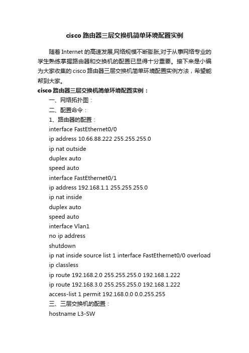
cisco路由器三层交换机简单环境配置实例随着Internet的高速发展,网络规模不断膨胀,对于从事网络专业的学生熟练掌握路由器和交换机的配置已显得十分重要。
接下来是小编为大家收集的cisco路由器三层交换机简单环境配置实例方法,希望能帮到大家。
cisco路由器三层交换机简单环境配置实例:一、网络拓扑图:二、配置命令:1、路由器的配置:interface FastEthernet0/0ip address 10.66.88.222 255.255.255.0ip nat outsideduplex autospeed autointerface FastEthernet0/1ip address 192.168.1.1 255.255.255.0ip nat insideduplex autospeed autointerface Vlan1no ip addressshutdownip nat inside source list 1 interface FastEthernet0/0 overload ip classlessip route 192.168.2.0 255.255.255.0 192.168.1.222ip route 192.168.3.0 255.255.255.0 192.168.1.222access-list 1 permit 192.168.0.0 0.0.255.255三、三层交换机的配置:hostname L3-SWip dhcp pool vlan2poolnetwork 192.168.3.0 255.255.255.0 default-router 192.168.3.1dns-server 202.101.172.35ip dhcp pool vlan1poolnetwork 192.168.2.0 255.255.255.0 default-router 192.168.2.1dns-server 202.101.172.35interface FastEthernet0/1no switchportip address 192.168.1.222 255.255.255.0 duplex autospeed autointerface FastEthernet0/2 switchport mode trunkinterface FastEthernet0/5 switchport mode trunkinterface Vlan1ip address 192.168.2.1 255.255.255.0 interface Vlan2ip address 192.168.3.1 255.255.255.0 ip classlessip route 0.0.0.0 0.0.0.0 192.168.1.1四、二层交换机的配置:1、switch0的配置:hostname sw0interface FastEthernet0/1 switchport mode trunkinterface FastEthernet0/2 switchport mode access2、switch1的配置:hostname sw1interface FastEthernet0/1switchport mode trunkinterface FastEthernet0/2switchport access vlan 2switchport mode access看了“cisco路由器三层交换机简单环境配置实例”还想看:1.思科交换机基本配置实例讲解2.三层交换机配置的实例教程3.cisco路由器怎么在虚拟环境下配置三层交换4.cisco2960交换机的简单配置5.交换机配置基础及实例讲解6.思科三层交换机与路由器的比较方法7.思科交换机配置教程详解。
Cisco3560三层交换机VLAN的配置案例

3、网络拓扑图
4、配置三层交换机 本例以思科三层交换机为例,具体配置命令如下所示:
1)、创建5个vlan 3560(config)#vlan 10 3560(config-vlan)#vlan 20 3560(config-vlan)#vlan 30 3560(config-vlan)#vlan 40 3560(config-vlan)#vlan 50 3560(config-vlan)#exit
2、各机房IP地址分配
机房一、二: IP:192.168.7.X/24,网关:192.168.7.254 机房三、四: IP:192.168.8.X/24,网关:192.168.8.254 机房五、六: IP:192.168.10.X/24,网关:192.168.10.254 机房七: IP:192.168.11.X/24,网关:192.168.11.254 服务器: IP:192.168.12.X/24 网关:192.168.12.254
2)、将端口划分到相应的VLAN
3560(config)#int range f0/1-5 3560(config-if-range)#switchport mode access 3560(config-if-range)#switchport access vlan10 3560(config-if-range)#exit 3560(config)#int range f0/6-10 3560(config-if-range)#switchport mode access 3560(config-if-range)#switchport access vlan20 3560(config-if-range)#exit 3560(config)#int range f0/11-15 3560(config-if-range)#switchport mode access 3560(config-if-range)#switchport access vlan30 3560(config-if-range)#exit 3560(config)#int range f0/16-20
思科三层交换机配置实例及命令
思科三层交换机配置实例及命令 交换机的命名⼀般是WS开头这个是固定的,再下⼀个字母有两种⼀个是C⼀个是X,C代表固化交换机或者机箱,X代表的是模块。
下⾯是店铺精⼼整理的思科三层交换机配置实例及命令,仅供参考,希望能够帮助到⼤家。
三层交换机是不是经常让你机器不好使,看看下⾯的三层交换机配置⽂章,⼀切问题都能解决。
本⽂详细介绍实例讲解:全⾯的三层交换机配置⽐较全⾯的三层交换机配置实例,带命令解释哟! 三层交换机配置: Enable //进⼊私有模式 Configure terminal //进⼊全局模式 service password-encryption //对密码进⾏加密 hostname Catalyst 3550-12T1 //给三层交换机定义名称 enable password 123456. //enable密码 Enable secret 654321 //enable的加密密码(应该是乱码⽽不是654321这样) Ip subnet-zero //允许使⽤全0⼦⽹(默认都是打开的) Ip name-server 172.16.8.1 172.16.8.2 //三层交换机名字Catalyst 3550-12T1对应的IP地址是172.16.8.1 Service dhcp //提供DHCP服务 ip routing //启⽤三层交换机上的路由模块 Exit 三层交换机配置: Vtp mode server //定义VTP⼯作模式为sever模式 Vtp domain centervtp //定义VTP域的名称为centervtp Vlan 2 name vlan2 //定义vlan并给vlan取名(如果不取名的话,vlan2的名字应该是vlan002) Vlan 3 name vlan3 Vlan 4 name vlan4 Vlan 5 name vlan5 Vlan 6 name vlan6 Vlan 7 name vlan7 Vlan 8 name vlan8 Vlan 9 name vlan9 Exit 三层交换机配置: interface Port-channel 1 //进⼊虚拟的以太通道组1 switchport trunk encapsulation dot1q //给这个接⼝的trunk封装为802.1Q的帧格式 switchport mode trunk //定义这个接⼝的⼯作模式为trunk switchport trunk allowed vlan all //在这个trunk上允许所有的vlan通过 Interface gigabitethernet 0/1 //进⼊模块0上的吉⽐特以太⼝1 switchport trunk encapsulation dotlq //给这个接⼝的trunk封装为802.1Q的帧格式 switchport mode trunk //定义这个接⼝的⼯作模式为trunk switchport trunk allowed vlan all //在这个trunk上允许所有的vlan通过 channel-group 1 mode on //把这个接⼝放到快速以太通道组1中 Interface gigabitethernet 0/2 //同上 switchport trunk encapsulation dotlq switchport mode trunk switchport trunk allowed vlan all channel-group 1 mode on 三层交换机配置: port-channel load-balance src-dst-ip //定义快速以太通道组的负载均衡⽅式(依*源和⽬的IP的⽅式) interface gigabitethernet 0/3 //进⼊模块0上的.吉⽐特以太⼝3 switchport trunk encapsulation dotlq //给trunk封装为802.1Q switchport mode trunk //定义这个接⼝的⼯作模式为trunk switchport trunk allowed vlan all //允许所有vlan信息通过 interface gigabitethernet 0/4 //同上 switchport trunk encapsulation dotlq switchport mode trunk switchport trunk allowed vlan all interface gigbitethernet 0/5 //同上 switchport trunk encapsulation dotlq switchport mode trunk switchport trunk allowed vlan all interface gigbitethernet 0/6 //同上 switchport trunk encapsulation dotlq switchport mode trunk switchprot trunk allowed vlan all 三层交换机配置: interface gigbitethernet 0/7 //进⼊模块0上的吉⽐特以太⼝7 Switchport mode access //定义这个接⼝的⼯作模式为访问模式 switchport access vlan 9 //定义这个接⼝可以访问哪个vlan(实际就是分配这个接⼝到vlan) no shutdown spanning-tree vlan 6-9 cost 1000 //在⽣成树中,vlan6-9的开销定义为10000 interface range gigabitethernet 0/8 – 10 //进⼊模块0上的吉⽐特以太⼝8,9,10 switchport mode access //定义这些接⼝的⼯作模式为访问模式 switchport access vlan 8 //把这些接⼝都分配到vlan8中 no shutdown 三层交换机配置: spanning-tree portfast //在这些接⼝上使⽤portfast(使⽤portfast以后,在⽣成树的时候不参加运算,直接成为转发状态) interface gigabitethernet 0/11 //进⼊模块0上的吉⽐特以太⼝11 switchport trunk encapsulation dotlq //给这个接⼝封装为802.1Q switchport mode trunk //定义这个接⼝的⼯作模式为trunk switchport trunk allowed vlan all //允许所有vlan信息通过 interface gigabitethernet 0/12 //同上 switchport trunk encapsulation dotlq switchport mode trunk switchport trunk allowed vlan all interface vlan 1 //进⼊vlan1的逻辑接⼝(不是物理接⼝,⽤来给vlan做路由⽤) ip address 172.16.1.7 255.255.255.0 //配置IP地址和⼦⽹掩码 no shutdown 三层交换机配置: standby 1 ip 172.16.1.9 //开启了冗余热备份(HSRP),冗余热备份组1,虚拟路由器的IP地址为172.16.1.9 standby 1 priority 110 preempt //定义这个三层交换机在冗余热备份组1中的优先级为110,preempt是⽤来开启抢占模式 interface vlan 2 //同上 ip address 172.16.2.252 255.255.255.0 no shutdown standby 2 ip 172.16.2.254 standby 2 priority 110 preempt ip access-group 101 in //在⼊⽅向上使⽤扩展的访问控制列表101 interface vlan 3 //同上 ip address 172.16.3.252 255.255.255.0 no shutdown 三层交换机配置: standby 3 ip 172.16.3.254 standby 3 priority 110 preempt ip access-group 101 in interface vlan 4 //同上 ip address 172.16.4.252 255.255.255.0 no shutdown standby 4 ip 172.16.4.254 standby 4 priority 110 preempt ip access-group 101 in interface vlan 5 ip address 172.16.5.252 255.255.255.0 no shutdown standby 5 ip 172.16.5.254 standby 5 priority 110 preempt ip access-group 101 in interface vlan 6 ip address 172.16.6.252 255.255.255.0 no shutdown 三层交换机配置: standby 6 ip 172.16.6.254 standby 6 priority 100 preempt interface vlan 7 ip address 172.16.7.252 255.255.255.0 no shutdown standby 7 ip 172.16.7.254 standby 7 priority 100 preempt interface vlan 8 ip address 172.16.8.252 255.255.255.0 no shutdown standby 8 ip 172.16.8.254 standby 8 priority 100 preempt interface vlan 9 ip address 172.16.9.252 255.255.255.0 no shutdown 三层交换机配置: standby 9 ip 172.16.9.254 standby 9 priority 100 preempt access-list 101 deny ip any 172.16.7.0 0.0.0.255 //扩展的访问控制列表101 access-list 101 permit ip any any Interface vlan 1 //进⼊vlan1这个逻辑接⼝ Ip helper-address 172.16.8.1 //可以转发⼴播(helper-address的作⽤就是把⼴播转化为单播,然后发向172.16.8.1) Interface vlan 2 Ip helper-address 172.16.8.1 Interface vlan 3 ip helper-address 172.16.8.1 interface vlan 4 ip helper-address 172.16.8.1 interface vlan 5 ip helper-address 172.16.8.1 interface vlan 6 ip helper-address 172.16.8.1 interface vlan 7 ip helper-address 172.16.8.1 interface vlan 9 ip helper-address 172.16.8.1 router rip//启⽤路由协议RIP version 2//使⽤的是RIPv2,如果没有这句,则是使⽤RIPv1 network 172.16.0.0//宣告直连的⽹段 exit 三层交换机配置: ip route 0.0.0.0 0.0.0.0 172.16.9.250//缺省路由,所有在路由表中没有办法匹配的数据包,都发向下⼀跳地址为172.16.9.250这个路由器 line con 0 line aux 0 line vty 0 15//telnet线路(路由器只有5个,是0-4) password 12345678//login密码 login end copy running-config startup-config 保存配置。
Cisco三层交换机与Routeros OSPF+DHCP服务器配置实例
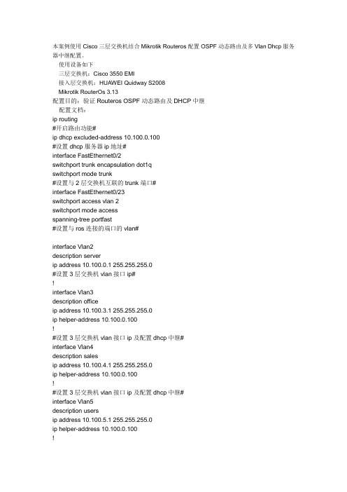
本案例使用Cisco三层交换机结合Mikrotik Routeros配置OSPF动态路由及多Vlan Dhcp服务器中继配置。
使用设备如下三层交换机:Cisco 3550 EMI接入层交换机:HUAWEI Quidway S2008Mikrotik RouterOs 3.13配置目的:验证Routeros OSPF动态路由及DHCP中继配置文档:ip routing#开启路由功能#ip dhcp excluded-address 10.100.0.100#设置dhcp服务器ip地址#interface FastEthernet0/2switchport trunk encapsulation dot1qswitchport mode trunk#设置与2层交换机互联的trunk端口#interface FastEthernet0/23switchport access vlan 2switchport mode accessspanning-tree portfast#设置与ros连接的端口的vlan#interface Vlan2description serverip address 10.100.0.1 255.255.255.0#设置3层交换机vlan接口ip#!interface Vlan3description officeip address 10.100.3.1 255.255.255.0ip helper-address 10.100.0.100!#设置3层交换机vlan接口ip及配置dhcp中继#interface Vlan4description salesip address 10.100.4.1 255.255.255.0ip helper-address 10.100.0.100!#设置3层交换机vlan接口ip及配置dhcp中继#interface Vlan5description usersip address 10.100.5.1 255.255.255.0ip helper-address 10.100.0.100!#设置3层交换机vlan接口ip及配置dhcp中继#router ospf 10router-id 10.100.0.1log-adjacency-changesnetwork 10.100.0.0 0.0.255.255 area 10.100.0.0#配置ospf进程及area信息#HUAWEI Quidway S2008 配置:interface Ethernet0/6switchport access vlan 5!#配置用户端口#interface Ethernet0/7switchport access vlan 3!#配置用户端口#interface Ethernet0/8switchport access vlan 4#配置用户端口#interface Ethernet0/9switchport mode trunkswitchport trunk allowed vlan all!#设置与3层交换机互联的trunk端口#Mikrotik Routeros:/ip pooladd name="vlan3" ranges=10.100.3.2-10.100.3.254add name="vlan4" ranges=10.100.4.2-10.100.4.254add name="vlan5" ranges=10.100.5.2-10.100.5.254#设置不同Vlan的地址池#/ip dhcp-serveradd address-pool=vlan3 authoritative=after-2sec-delay bootp-support=static \ disabled=no interface=in lease-time=3d name="vlan3" relay=10.100.3.1 add address-pool=vlan4 authoritative=after-2sec-delay bootp-support=static \ disabled=no interface=in lease-time=3d name="vlan4" relay=10.100.4.1 add address-pool=vlan5 authoritative=after-2sec-delay bootp-support=static \ disabled=no interface=in lease-time=3d name="vlan5" relay=10.100.5.1#设置Dhcp-server 使之支持Dhcp中继#/routing ospf areaadd area-id=0.0.0.0 authentication=none disabled=no name="backbone" \type=defaultadd area-id=10.100.0.0 authentication=none disabled=no name="area1" \type=default#配置ospf area#/ip addressadd address=10.100.0.100/24 broadcast=10.100.0.255 comment="" disabled=no \ interface=in network=10.100.0.0#配置内部IP地址#/ip dnsset allow-remote-requests=yes cache-max-ttl=1w cache-size=2048KiB \max-udp-packet-size=512 primary-dns=192.168.100.208 \#配置dns#/ip firewall natadd action=masquerade chain=srcnat comment="" disabled=no \src-address=10.100.0.0/16#配置NAT#/routing ospfset distribute-default=always-as-type-2 metric-bgp=20 metric-connected=20 \metric-default=1 metric-rip=20 metric-static=20 mpls-te-area=unspecified \mpls-te-router-id=unspecified redistribute-bgp=no \redistribute-connected=no redistribute-rip=no redistribute-static=no \router-id=10.100.100.2/routing ospf interfaceadd authentication=none authentication-key="" cost=10 dead-interval=40s \disabled=no hello-interval=10s interface=in network-type=broadcast \passive=no priority=1 retransmit-interval=5s transmit-delay=1s/routing ospf networkadd area=area1 disabled=no network=10.100.0.0/16#配置OSPF路由协议#cisco3550#show ip routeCodes: C - connected, S - static, R - RIP, M - mobile, B - BGPD - EIGRP, EX - EIGRP external, O - OSPF, IA - OSPF inter areaN1 - OSPF NSSA external type 1, N2 - OSPF NSSA external type 2E1 - OSPF external type 1, E2 - OSPF external type 2, E - EGPi - IS-IS, su - IS-IS summary, L1 - IS-IS level-1, L2 - IS-IS level-2ia - IS-IS inter area, * - candidate default, U - per-user static routeo - ODR, P - periodic downloaded static routeGateway of last resort is 10.100.0.100 to network 0.0.0.010.0.0.0/24 is subnetted, 4 subnetsC 10.100.4.0 is directly connected, Vlan4C 10.100.5.0 is directly connected, Vlan5C 10.100.3.0 is directly connected, Vlan3C 10.100.0.0 is directly connected, Vlan2O*E2 0.0.0.0/0 [110/1] via 10.100.0.100, 01:09:52, Vlan2[admin@MikroTik] /ip route> printFlags: X - disabled, A - active, D - dynamic, C - connect, S - static, r - rip, b - bgp, o - ospf, m - mme, B - blackhole, U - unreachable, P - prohibit# DST-ADDRESS PREF-SRC GATEWAY-STATEGATEWAY DISTANCE INTERFACEADS 0.0.0.0/0 reachable 192.168.18.1 0 o ut1ADC 10.100.0.0/24 10.100.0.100 0 in2ADo 10.100.3.0/24 reachable 10.100.0.1 110 in3ADo 10.100.4.0/24 reachable 10.100.0.1 110 in4ADo 10.100.5.0/24 reachable 10.100.0.1 110 in5ADC 192.168.18.0/24 192.168.18.158 0 out。
三层交换配置实例
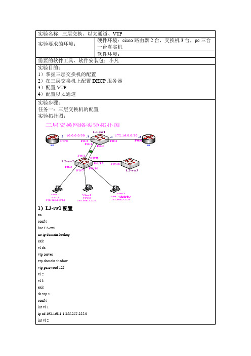
实验拓扑图:
1)SW1配置
en
conf t
hos sw1
no ip domain
int fa0/0
sw mo tr
no sh
int fa0/3
sw mo tr
no sh
end
vl da
vtp server
vtp domain shadow
vtp password 123
vtp pruning
sw ac vl 3
no sh
exit
sh vlan-s
4)R1配置
en
conf t
hos R1
int fa0/0
ip ad 172.16.0.2 255.255.255.252
no sh
int loopback 0
ip ad10.10.10.10 255.255.255.0
exit
ip route 100.100.100.0 255.255.255.0 172.16.0.1
vtp v2
vl 2
vl 3
exit
sh vtp s
sh vlan-s
2)SW2配置
en
conf t
hos sw2
int range fa0/0
sw mo tr
no sh
end
vlan database
vtp server
vtp domain shadow
vtp password 123
exit
sh vtp status
exit
6)监测配置
6.1 show ip ro查看三层交换机上的路由表,可以看到非直连的路由以及vlan的路由信息
思科三层交换机基于环形网络的配置方案(初学者的宝典)

Cisco三层交换机网络配置方案二vlan设置此处的实验划分了3个vlan,一个服务器组,一个子站的主环形通道,一个子站的备环形通道。
如果有多个环形通道,按照文章中的主备环形通道的配置方法增加配置即可。
本片文章是以Cisco 3560编写的,配置3750与3560不一样的地方会在每一部分的开头标出,如果没有标出就是两种交换机的配置方法是一样的。
如果配置的是3750(或者其他型号的可堆叠Cisco交换机),请先参阅4.6。
2.1 进入配置模式2.1.1 进入特权模式Switch>en如图6所示。
图 62.1.2 进入配置模式Switch#configure terminal如图7所示。
hou图7进入配置模式后就可以开始划分vlan了(关于“模式”的解释请查阅4.2)。
2.2 划分vlan2.2.1 配置交换机的名称Switch(config)#hostname switch1如图8所示。
图82.2.2 划分3个vlanswitch1(config)#vlan 10 !全局配置模式下进入vlan模式并创建vlan10 switch1(config-vlan)#name commmaster !把vlan10命名为commmasterswitch1(config-vlan)#vlan 20 !vlan模式下创建vlan20switch1(config-vlan)#name commbak !把vlan20命名为commbakswitch1(config-vlan)#vlan 30 !vlan模式下创建vlan30switch1(config-vlan)# name server !把vlan30命名为serverswitch1naswitch1(config)#如图9所示。
图92.2.3 分配端口3560端口1的名称是g0/1,3750堆叠后交换机1的端口1名称是Gi1/0/1。
交换机端口的名字是什么可在特权模式(即switch1#)下用sh vlan brief查看。
思科三层交换机路由功能配置教程

思科三层交换机路由功能配置教程交换机工作于OSI参考模型的第二层,即数据链路层。
交换机内部的CPU会在每个端口成功连接时,通过将MAC地址和端口对应,形成一张MAC表,在思科三层交换机中,路由功能是很重要的功能,需要做好正确配置,下面一起看看!方法步骤而三层交换机可以在网络层配置路由功能,使不同网段的设备可以通信。
现以思科3550交换机为例配置三层路由功能。
以实现如下拓扑通信。
----------------------------------| 思科3550三层交换机 |---- -------------------- -------50.1.1.1 (23口) 60.1.1.1(24口)|| |||| ||50.1.1.2 60.1.1.2(pc1) (pc2)配置23口:Switch#enableSwitch#configure terminalSwitch(config)#interface fastEthernet 0/23Switch(config)ip addr 50.1.1.1 255.255.255.0Switch(config-if)#no switchportSwitch(config-if)#no shutdownSwitch(config-if)#end类似的配置24口:Switch#enableSwitch#configure terminalSwitch(config)#interface fastEthernet 0/24Switch(config)ip addr 60.1.1.1 255.255.255.0Switch(config-if)#no switchportSwitch(config-if)#no shutdownSwitch(config-if)#end打开交换机路由转发开关:Switch#configure terminalSwitch(config)#ip routingSwitch(config)#ip cef (这个默认是打开的)此时可以查看下23口的状态:Switch#show interfaces fastEthernet 0/23此时在交换机上ping两个口的地址成功:Switch#ping 50.1.1.1Type escape sequence to abort.Sending 5, 100-byte ICMP Echos to 50.1.1.1, timeout is 2 seconds:Success rate is 100 percent (5/5), round-trip min/avg/max = 1/1/1 msSwitch#ping 60.1.1.1Type escape sequence to abort.Sending 5, 100-byte ICMP Echos to 60.1.1.1, timeout is 2 seconds:Success rate is 100 percent (5/5), round-trip min/avg/max = 1/1/4 msSwitch#pc1(win7)增加路由:到60.1.1.0/24的数据包通过50.1.1.1转发:route ADD 60.1.1.0 MASK 255.255.255.0 50.1.1.1 METRIC 3 对应的pc2也增加路由:route ADD 50.1.1.0 MASK 255.255.255.0 60.1.1.1 METRIC 3 此时50.1.1.2和60.1.1.2即可通信。
三层交换机链路聚合 [Cisco三层交换机链路聚合配置应用实例]
![三层交换机链路聚合 [Cisco三层交换机链路聚合配置应用实例]](https://img.taocdn.com/s3/m/b6986b6a77232f60dccca128.png)
竭诚为您提供优质的服务,优质的文档,谢谢阅读/双击去除三层交换机链路聚合 [Cisco三层交换机链路聚合配置应用实例]交换机是计算机网络的基础核心设备,因此有效的管理好交换机是解决网络安全以及可靠性的关键。
接下来是小编为大家收集的cisco三层交换机链路聚合配置应用实例方法,希望能帮到大家。
cisco三层交换机链路聚合配置应用实例的方法交换机连接拓扑图如下:步骤:一、两台三层交换机上创建vlan:sw0#conftsw0(configure)#vlan10sw0(configure-vlan)#exitsw0(configure)#vlan11sw0(configure-vlan)#exit二、在sw0交换机上将端口fa0/1-2加入到vlan10中,端口fa0/3加入到vlan11中sw0(configure)#intrangefa0/1-2sw0(configure-if-range)#switchportaccessvlan10 sw0(configure-if-range)#exitsw0(configure)#intfa0/3sw0(configure-if)#switchportaccessvlan11sw0(configure)#exit三、在sw1交换机上将fa0/1-2号端口加入到vlan10中,将fa0/3号端口加到vlan100中sw1#conftsw1(configure)#intrangefa0/1-2sw1(configure-if-range)#switchportaccessvlan10 sw1(configure-if-range)#exitsw1(configure)#intfa0/3sw1(configure-if)#switchportaccessvlan100sw1(configure-if)#exit四、在sw0和sw1交换机上为每个vlan配置虚拟ip地址sw0#conftsw0(configure)#intvlan10sw0(configure-if-vlan)#ipaddress192.168.10.253255.2 55.255.0sw0(configure-if-vlan)#noshutdownsw0(configure-if-vlan)#exitsw0(configure)#intvlan11sw0(configure-if-vlan)#ipaddresss192.168.11.254255. 255.255.0sw0(configure-if-vlan)#noshutdownsw0(configure-if-vlan)#exitsw1#conftsw1(configure)#intvlan10sw1(configure-if-vlan)#ipaddress192.168.10.254255.2 55.255.0sw1(configure-if-vlan)#noshutdownsw1(configure-if-vlan)#exitsw1(configure)#intvlan100sw1(configure-if-vlan)#ipaddress192.168.100.254255. 255.255.0sw1(configure-if-vlan)#noshutdownsw1(configure-if-vlan)#exit五、将sw0和sw1交换机相连的fa0/1-2口进行聚合sw0#conftsw0(configure)#intrangefa0/1-2sw0(configure-if-range)#channel-group1modedesirable sw0(configure-if-range)#exitsw1#conftsw1(configure)#intrangefa0/1-2sw1(configure-if-range)#channel-gropu1modedesirablesw1(configure-if-range)#exit【可选做】//六、在sw0和sw1交换机上将聚合端口设置为trunk口sw0#conftsw0(configure)#intport-channel1sw0(configure-if)#switchportmodetrunksw0(configure-if)#switchporttrunknativevlan10 sw0(configure-if)#exitsw1#conftsw1(configure)#intport-channel1sw1(configure-if)#switchportmodetrunksw1(configure-if)#switchporttrunknativevlan10 sw1(configure-if)#exit//七、在sw0和sw1交换机上设置默认路由(当然你也可以设置能实现路由功能的协议)sw0#conftsw0(configure)#iproute0.0.0.00.0.0.0192.168.10.254sw0(configure)#exitsw1#conftsw1(configure)#iproute0.0.0.00.0.0.0192.168.10.253sw1(configure)#exit八、测试在pc0客户端设置其ip地址为:192.168.11.1,子网掩码为:255.255.255.0,网关地址为:192.168.11.254在pc1客户端设置其ip地址:192.168.100.1,子网掩码为:255.255.255.0,网关地址为:192.168.100.254利用pc0客户端去pingpc1客户端的ip,检查是否能够ping即可*[注意]:在对sw0和sw1交换机上进行端口聚合后,如果没有设置聚合端口为trunk时,交换机两边是不能够被ping通的。
配置思科三层交换的综合案例

配置思科三层交换的综合案例网络基本情况网络拓扑结构为:中心交换机采用Cisco Catalyst 4006-S3,Supervisor Engine III G引擎位于第1插槽,用于实现三层交换;1块24口1000Base-T模块位于第2插槽,用于连接网络服务器;1块6端口1000Base-X模块位于第3插槽,用于连接6台骨干交换机。
一台交换机采用Cisco Catalyst 3550-24-EMI,并安装1块1000Base-X GBIC千兆模块。
一台交换机采用Cisco Catalyst 3550-24-SMI,也安装1块1000Base-X GBIC千兆模块。
另外四台交换机采用Cisco Catalyst 2950G-24-SMI,安装1块1000Base-T GBIC千兆模块。
所有服务器划分为一个VLAN,即VLAN 50。
四台Catalyst 2950G-24-SMI交换机也只划分为一个VLAN,分别为VLAN 60、VLAN 70、VLAN 80和VLAN 90。
Catalyst 3550-24-EMI划分为4个VLAN,分别为VLAN 10、VLAN 20、VLAN 30和VLAN 40。
Catalyst 3550-24-SMI划分2个VLAN,分别为VLAN 60和VLAN 80,与另外两台Catalyst 2950G-24-SMI交换机分别位于同一VLAN。
***************************实例分析****************************由于所有Catalyst 2950G交换机都是一个独立的VLAN,因此,必须先在这些交换机上创建VLAN(VLAN 60~VLAN 90),并将所有端口都指定至该VLAN。
然后,再在Catalyst 4006交换机相应端口上分别创建VLAN。
Catalyst 4006的1000Base-X端口分别与各Catalyst 2950G的1000Base-X端口连接。
2、思科模拟器 实验二(三层交换机VLAN配置)hao
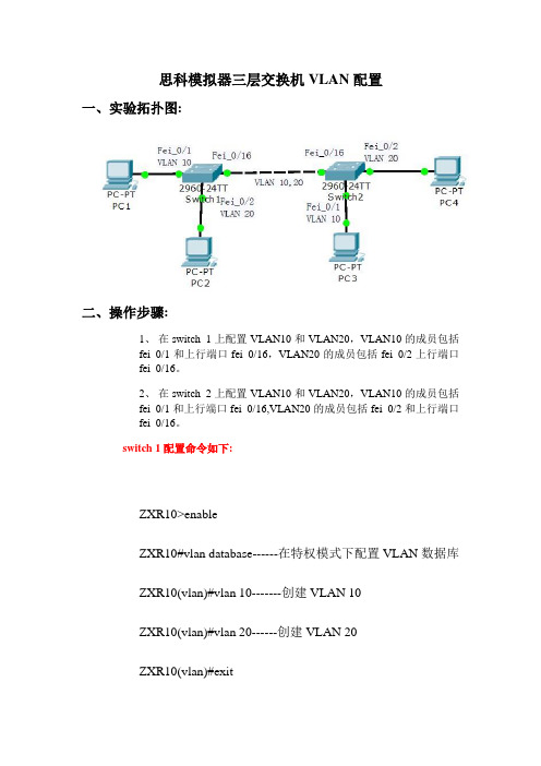
思科模拟器三层交换机VLAN配置一、实验拓扑图:交换机switch 1的端口fei_0/1和交换机switch 2的端口fei_0/1属于VLAN 10;交换机switch 1的端口fei_0/2和交换机switch 2的端口fei_0/2属于VLAN 20,均为Access端口。
两台交换机通过端口fei_0/16以Trunk方式连接,两端口为Trunk端口。
二、操作步骤:1、在switch 1上配置VLAN10和VLAN20,VLAN10的成员包括fei_0/1和上行端口fei_0/16,VLAN20的成员包括fei_0/2上行端口fei_0/16。
2、在switch 2上配置VLAN10和VLAN20,VLAN10的成员包括fei_0/1和上行端口fei_0/16,VLAN20的成员包括fei_0/2和上行端口fei_0/16。
switch 1配置命令如下:ZXR10>enableZXR10#vlan database------在特权模式下配置VLAN数据库ZXR10(vlan)#vlan 10-------创建VLAN 10ZXR10(vlan)#vlan 20------创建VLAN 20ZXR10(vlan)#exitZXR10#configure terminalZXR10(config)#1、进入端口fei_0/1,把端口fei_0/1加入vlan 10,fei_0/1模式为access;ZXR10(config)#interface fastethernet 0/1ZXR10(config-if)#switchport mode accessZXR10(config-if)#switchport access vlan 10ZXR10(config-if)#exit2、进入端口fei_0/2,把端口fei_0/2加入vlan 20,fei_0/2模式为access;ZXR10(config)#interface fastethernet 0/2ZXR10(config-if)#switchport mode accessZXR10(config-if)#switchport access vlan 20ZXR10(config-if)#exit3、进入fei_0/16端口,将该端口设置成trunk模式,并且把端口fei_0/16以trunk模式加入vlan10,vlan 20ZXR10(config)#interface fastethernet 0/16ZXR10(config-if)#switchport mode trunkZXR10(config-if)#switchport trunk allowed vlan 10,20ZXR10(config-if)#endZXR10#write---------保存文件(备注:switch 2配置命令同switch 1一样)三、验证方法:1. PC-1和PC-2不能互通,PC-3和PC-4不能互通2. PC-1和PC-3互通,PC-2和PC-4互通。
- 1、下载文档前请自行甄别文档内容的完整性,平台不提供额外的编辑、内容补充、找答案等附加服务。
- 2、"仅部分预览"的文档,不可在线预览部分如存在完整性等问题,可反馈申请退款(可完整预览的文档不适用该条件!)。
- 3、如文档侵犯您的权益,请联系客服反馈,我们会尽快为您处理(人工客服工作时间:9:00-18:30)。
比较全面的三层交换机配置实例(带命令解释哟!)Enable //进入私有模式Configure terminal //进入全局模式service password-encryption //对密码进行加密hostname Catalyst 3550-12T1 //给三层交换机定义名称enable password 123456. //enable密码Enable secret 654321 //enable的加密密码(应该是乱码而不是654321这样)Ip subnet-zero //允许使用全0子网(默认都是打开的)Ip name-server 172.16.8.1 172.16.8.2 //三层交换机名字Catalyst 3550-12T1对应的IP地址是172.16.8.1Service dhcp //提供DHCP服务ip routing //启用三层交换机上的路由模块ExitVtp mode server //定义VTP工作模式为sever模式Vtp domain centervtp //定义VTP域的名称为centervtpVlan 2 name vlan2 //定义vlan并给vlan取名(如果不取名的话,vlan2的名字应该是vlan002)Vlan 3 name vlan3Vlan 4 name vlan4Vlan 5 name vlan5Vlan 6 name vlan6Vlan 7 name vlan7Vlan 8 name vlan8Vlan 9 name vlan9Exitinterface Port-channel 1 //进入虚拟的以太通道组1switchport trunk encapsulation dot1q //给这个接口的trunk封装为802.1Q的帧格式switchport mode trunk //定义这个接口的工作模式为trunkswitchport trunk allowed vlan all //在这个trunk上允许所有的vlan通过Interface gigabitethernet 0/1 //进入模块0上的吉比特以太口1switchport trunk encapsulation dotlq //给这个接口的trunk封装为802.1Q的帧格式switchport mode trunk //定义这个接口的工作模式为trunkswitchport trunk allowed vlan all //在这个trunk上允许所有的vlan通过channel-group 1 mode on //把这个接口放到快速以太通道组1中Interface gigabitethernet 0/2 //同上switchport trunk encapsulation dotlqswitchport mode trunkswitchport trunk allowed vlan allchannel-group 1 mode onport-channel load-balance src-dst-ip //定义快速以太通道组的负载均衡方式(依*源和目的IP的方式)interface gigabitethernet 0/3 //进入模块0上的吉比特以太口3switchport trunk encapsulation dotlq //给trunk封装为802.1Qswitchport mode trunk //定义这个接口的工作模式为trunkswitchport trunk allowed vlan all //允许所有vlan信息通过interface gigabitethernet 0/4 //同上switchport trunk encapsulation dotlqswitchport mode trunkswitchport trunk allowed vlan allinterface gigbitethernet 0/5 //同上switchport trunk encapsulation dotlqswitchport mode trunkswitchport trunk allowed vlan allinterface gigbitethernet 0/6 //同上switchport trunk encapsulation dotlqswitchport mode trunkswitchprot trunk allowed vlan allinterface gigbitethernet 0/7 //进入模块0上的吉比特以太口7Switchport mode access //定义这个接口的工作模式为访问模式switchport access vlan 9 //定义这个接口可以访问哪个vlan(实际就是分配这个接口到vlan)no shutdownspanning-tree vlan 6-9 cost 1000 //在生成树中,vlan6-9的开销定义为10000interface range gigabitethernet 0/8 – 10 //进入模块0上的吉比特以太口8,9,10switchport mode access //定义这些接口的工作模式为访问模式switchport access vlan 8 //把这些接口都分配到vlan8中no shutdownspanning-tree portfast //在这些接口上使用portfast(使用portfast以后,在生成树的时候不参加运算,直接成为转发状态)interface gigabitethernet 0/11 //进入模块0上的吉比特以太口11switchport trunk encapsulation dotlq //给这个接口封装为802.1Qswitchport mode trunk //定义这个接口的工作模式为trunkswitchport trunk allowed vlan all //允许所有vlan信息通过interface gigabitethernet 0/12 //同上switchport trunk encapsulation dotlqswitchport mode trunkswitchport trunk allowed vlan allinterface vlan 1 //进入vlan1的逻辑接口(不是物理接口,用来给vlan做路由用)ip address 172.16.1.7 255.255.255.0 //配置IP地址和子网掩码no shutdownstandby 1 ip 172.16.1.9 //开启了冗余热备份(HSRP),冗余热备份组1,虚拟路由器的IP地址为172.16.1.9standby 1 priority 110 preempt //定义这个三层交换机在冗余热备份组1中的优先级为110,preempt是用来开启抢占模式interface vlan 2 //同上ip address 172.16.2.252 255.255.255.0no shutdownstandby 2 ip 172.16.2.254standby 2 priority 110 preemptip access-group 101 in //在入方向上使用扩展的访问控制列表101interface vlan 3 //同上ip address 172.16.3.252 255.255.255.0no shutdownstandby 3 ip 172.16.3.254standby 3 priority 110 preemptip access-group 101 ininterface vlan 4 //同上ip address 172.16.4.252 255.255.255.0no shutdownstandby 4 ip 172.16.4.254standby 4 priority 110 preemptip access-group 101 ininterface vlan 5ip address 172.16.5.252 255.255.255.0no shutdownstandby 5 ip 172.16.5.254standby 5 priority 110 preemptip access-group 101 ininterface vlan 6ip address 172.16.6.252 255.255.255.0no shutdownstandby 6 ip 172.16.6.254standby 6 priority 100 preemptinterface vlan 7ip address 172.16.7.252 255.255.255.0no shutdownstandby 7 ip 172.16.7.254standby 7 priority 100 preemptinterface vlan 8ip address 172.16.8.252 255.255.255.0no shutdownstandby 8 ip 172.16.8.254standby 8 priority 100 preemptinterface vlan 9ip address 172.16.9.252 255.255.255.0no shutdownstandby 9 ip 172.16.9.254standby 9 priority 100 preemptaccess-list 101 deny ip any 172.16.7.0 0.0.0.255 //扩展的访问控制列表101access-list 101 permit ip any anyInterface vlan 1 //进入vlan1这个逻辑接口Ip helper-address 172.16.8.1 //可以转发广播(helper-address的作用就是把广播转化为单播,然后发向172.16.8.1)Interface vlan 2Ip helper-address 172.16.8.1Interface vlan 3ip helper-address 172.16.8.1interface vlan 4ip helper-address 172.16.8.1interface vlan 5ip helper-address 172.16.8.1interface vlan 6ip helper-address 172.16.8.1interface vlan 7ip helper-address 172.16.8.1interface vlan 9ip helper-address 172.16.8.1router rip //启用路由协议RIPversion 2 //使用的是RIPv2,如果没有这句,则是使用RIPv1network 172.16.0.0 //宣告直连的网段exitip route 0.0.0.0 0.0.0.0 172.16.9.250 //缺省路由,所有在路由表中没有办法匹配的数据包,都发向下一跳地址为172.16.9.250这个路由器line con 0line aux 0line vty 0 15 //telnet线路(路由器只有5个,是0-4)password 12345678 //login密码loginendcopy running-config startup-config 保存配置。