P+F安全栅说明书(中文)
P+F安全栅
对比齐纳式和隔离式安全栅的特点和性能后可以看出,隔离式 安全栅 有着突出的优点和更为广泛用途,虽然其价格略高于 齐纳式安全栅,但从设计、施工安装、调试及维护成本来考虑 , 其综合成本可能反而低于齐纳式安全栅。在要求较高的工 程现场几 乎无一例外地采用了隔离式安全栅作为主要本安防 爆仪表, 隔离式安全栅已逐渐取代了齐纳 式安全栅,在安全 防爆领域得到了日益广泛的应用。
路,给设计及现场施工带来 极大方便。 2.对危险 区的仪表要求大幅度降低,现场无需采用隔离式的 仪表。 3.由于信号线路无需共地,使得检测和控制 回路信号的稳定性和抗干扰能力大 大增强,从而提 高了整个系统的可靠性。 4.隔离式安全栅具备更强 的输入信号处理能力,能够接受并处理热电偶、热 电 阻、频率等信号,这是齐纳式安全栅所无法做到 的。 5.隔离式安全栅可输出两路相互隔离的信号, 以提供给使用同一信号源的两台设备使用,并保证 两设备信号不互相干扰,同时提高所连接设备相互 之间的电气安全绝缘性能。
P+F安全栅的组态主要指对温变式安全栅的 组态,下面我们大概了解一下,温变式安全 栅组态软件的安装与一般组态。
2015.11.16
安装位置:安全栅安装于安全场所,接收来自危险区的信号,输 出安全信号到安全区或危险区。 安全栅的结构形式:常见的分为齐纳式和隔离式安全栅 齐纳式安全栅:电路中采用快速熔断器、限流电阻或限压二 极管以对输入的电能量进行限制,从而保证输出到危险区的 能量。 隔离式安全栅:采用了将输入、输出以及电源三方之间相互 电气隔离的电路结构,同时符合本安型限制能量的要求。
隔离式安全栅
隔离式安全栅:带有电流隔离功能的安全栅,称为隔离式安全栅,简称隔 离栅。 构成:通常由回路限能单元、电流隔离单元、信号处理单元 回路限能单元中最核心的电路为安全栅基本限能电路,辅助有用于驱动现 场仪表的回路供电电路和用于仪表信号采集的检测电路。 电流隔离单元包括变压器隔离组件、模频转换和频模转换电路。 信号处理单元则根据各品种隔离栅的功能要求实施信号处理。
P+F安全栅资料

P+F安全栅及现场总线产品德国Pepperl+Fuchs公司成立于1945年。
1958年,P+F发明的世界首例本安型接近开关及与之世界的隔离式安全栅使工业防爆应用领域发生了全新的变革。
如今,P+F公司已发展成为世界上最大、最有经验的本安接口生产商。
其安全栅品种之丰富、处理特殊应用难题之能力一直处于世界领先地位。
其产品应用遍及石油、天然气、化工、石化、医药等存在易燃易爆危险场所的工业领域。
P+F积极推动本质安全技术面向现场总线时代的新变革。
P+F远程I/O型隔离栅RPI和本安型远程I/O系统IS-RPI已经开始对本安接口的应用产生深远的影响。
P+F的FieldConnex现场总线产品家族包含了将现场总线主机与现场仪表相连接的全套配件产品,包括各种网桥、现场总线配电器、现场总线中继器、现场总线I/O模盒、接线盒、现场总线安全栅、快速接插件等现场总线产品,更使本安防爆的现场总线全面进入实用阶段。
P+F公司的产品不仅符合德国、欧洲和国际(IEC)标准,其专业化的研究和开发工作,还曾经并继续为这些标准的制定提供依据。
P+F公司的所有生产和开发机构均获得ISO9001质量保证体系认证。
其产品还获得包括美国(FM)、中国(NEPSI)等世界诸多国家的防爆认证。
为确保完善的就近服务,P+F公司的过程自动化部(PA)和工厂自动化部(FA)在世界各主要国家和地区设立子公司和办事处。
在中国,P+F公司在北京、上海设有代表处和子公司,并在广州等全国各主要大城市设有办事机构。
P+F公司不仅仅是防爆技术专家,其经验和创造力还从其产品本身延伸至系统配套方面。
本样本将详述P+F齐纳栅、隔离栅与DCS和ESD控制系统配合的典型方案,并提供现场总线的配电、防爆和连接的典型方案。
P+F公司备有安全栅产品的详细的原版书面样本和CD-ROM样本及多种应用指南。
P+F 隔离栅的优势:轨道供电大部分隔离栅需要供电.当隔离栅使用数量较大时,给隔离栅配电不是一件轻松的工作.为了简化隔离栅的配电,P+F公司发明了轨道供电方式。
p+f转速安全栅组态参数说明

p+f转速安全栅组态参数说明P+F转速安全栅组态参数说明转速安全栅是一种常用于工业环境中的安全设备,用于保护工人和设备免受意外事故的伤害。
P+F是一家专业从事传感器和安全设备生产的公司,他们提供了一系列转速安全栅产品。
为了正确使用这些产品,了解和正确设置组态参数是非常重要的。
本文将详细介绍P+F转速安全栅的组态参数及其说明。
一、组态参数的基本概念组态参数是指用户在使用转速安全栅时可以进行自定义设置的一些参数。
通过调整这些参数,可以满足不同情况下的安全需求。
下面将介绍几个常见的组态参数及其说明。
1. 保护区域设置保护区域是指转速安全栅有效的安全监控区域。
用户可以根据实际需求设置保护区域的大小和形状,确保安全栅能够正确监控到需要保护的区域。
2. 检测距离设置检测距离是指转速安全栅能够探测出物体的最大距离。
用户可以根据工作场所的具体情况设置检测距离,以确保安全栅能够及时发现潜在的危险物体并发出警报。
3. 响应时间设置响应时间是指转速安全栅从检测到物体进入保护区域到发出警报的时间。
用户可以根据实际需求设置响应时间,以确保安全栅能够在最短时间内发出警报,保护工人和设备的安全。
二、转速安全栅组态参数的设置方法为了正确设置转速安全栅的组态参数,用户可以按照以下步骤进行操作。
1. 进入设置模式首先,用户需要进入转速安全栅的设置模式。
具体的方法可以在产品说明书中找到,一般是通过按下设备上的特定按钮或者使用特定的遥控器来实现。
2. 导航菜单在设置模式下,用户将进入一个导航菜单界面。
在这个界面上,用户可以看到各个组态参数的选项。
3. 参数设置用户可以使用设备上的按键或者遥控器来选择并设置不同的组态参数。
一般来说,用户可以根据实际情况选择合适的数值或者选项来进行设置。
4. 保存设置设置完成后,用户需要保存设置。
一般来说,设备会有一个“保存”或者“确认”按钮,用户只需要按下这个按钮即可完成设置并保存。
三、转速安全栅组态参数设置注意事项在设置转速安全栅的组态参数时,需要注意以下几点。
光栅操作手册(P+F)

F A C T O R Y A U T O M A T I O N SLP/SLPC SLP/SLPCM 操作手册安全光栅With regard to the supply of products, the current issue of the following document is applicable: The General Terms of Delivery for Products and Services of the Electrical Industry,published by the Central Association of the Electrical Industry (Zentralverband Elektrotechnik und Elektroin-dustrie (ZVEI) e.V.)in its most recent version as well as the supplementary clause: "Expanded reservation of proprietorship"We at Pepperl+Fuchs/VISOLUX recognize a duty to make a contribution to the future.D a t e o f i s s u e 02/25/0238.3.4Test of error enable connection (RESET)...................................... 27SLP/SLPC 和 SLP/SLPCM 安全光栅目录章 页1 使用目的 ............................................ 62 产品描述 ............................................ 62.1 系统特点 .................................................... 62.2 工作原理 .................................................... 72.3 原理框图 .................................................... 83 电气连接 ........................................... 103.1 SLPC(M)端子区 .............................................. 103.2 SLPC(M)连接器 .............................................. 123.3 Muting 灯连接 / 灯插座(仅对SLPCM...-L...) ................ 133.4 SLP发射器的连接............................................. 144 状态指示 ........................................... 155 工作模式 ........................................... 165.1 启动 / 重启锁(Restart).................................... 175.2 继电器监控.................................................. 175.3 Muting(SLPCM)............................................. 185.3.1 工作原理.................................................... 195.3.1.1 平行或连续Muting方式下对Muting传感器的评估......................... 195.3.1.2 时间窗口限制或保护光束限制Muting方式下的Muting监控 ......................... 205.3.2 Muting传感器................................................ 225.3.2 Muting指示灯................................................ 225.4 紧急Muting(仅对SLPCM)..................................... 226 光栅的安装 ......................................... 237 电气安装布置 ....................................... 258.2 反射镜的布置................................................ 268.1 调整保护光束................................................ 268 调试 ............................................... 268.3 功能测试.................................................... 278.3.1 NCSE检测能力测试............................................ 278.3.2 Muting功能测试(仅对SLPCM)................................. 278.3.3 启动/重启锁和启动能力测试................................... 278.3.5 继电器监控测试.............................................. 288.3.6 OSSD工作原则................................................ 28D a t e o f i s s u e 02/25/02416.1Construction and equipping of safety equipment......................... 4416.2Use and installation of protective equipment................................ 44Please note!This instruction manual contains instruction explaining the intended use of the product and serves as a protection from danger. It must be read and observed by all persons who make use of, care for, maintain and monitor this product. This pro-duct can only accomplish the tasks for which it is intended if it is used, cared for,maintained and monitored in accordance with the instructions of Pepperl+Fuchs/Visolux.The warranty undertaken by Pepperl+Fuchs/Visolux for this product becomes null and void if it is not used, cared for, maintained and monitored in accordance with the instructions of Pepperl+Fuchs/Visolux.Before this product is used, an evaluation must be undertaken to determine whe-SLP/SLPC 和 SLP/SLPCM 安全光栅9 定期检查 ........................................... 2810 故障诊断 ........................................... 2911 技术参数 ........................................... 3011.1 电气参数及特性.............................................. 3011.2 外形尺寸.................................................... 3212 附件 ............................................... 3412.1 SLP安装支架................................................. 3412.2 SLP反射镜................................................... 3512.3 SLP保护镜................................................... 3612.4 SLP保护镜固定架............................................. 3612.5 SLP辅助对齐瞄准器........................................... 3612.6 SLP激光辅助对齐工具......................................... 3712.7 电缆连接器.................................................. 3712.8 电缆扎带.................................................... 3713 订购信息 ........................................... 3814 电路图示例 ......................................... 4015 术语表 ............................................. 4316 标准 ............................................... 4417 证书 ............................................... 45D a t e o f i s s u e 02/25/025ther it is suitable for the application at hand. Selection and use are not subject to influence on the part of Pepperl+Fuchs/Visolux. Our liability is thus restricted to consistent quality of the product.The product must be monitored and maintained by competent professionals. A re-cord must be kept of the results of inspections and maintenance tasks. Only ori-ginal Pepperl+Fuchs/Visolux parts must be used for repair jobs.The operator is not permitted to make changes to the machines or components thereof, or make use of defective or incomplete machines or components. Repairs to machines or components must only be performed by Pepperl+Fuchs/Visolux or by authorized workshops. Such workshops are responsible for acquiring the latest technical information about machines and components from Pepperl+Fuchs/Viso-lux.Repair tasks made on the product that are not performed by Pepperl+Fuchs/Viso-lux are not subject to influence on the part of Pepperl+Fuchs/Visolux.Our liability is thus limited to repair tasks that are performed by Pepperl+Fuchs/Visolux.The preceding information does not change information regarding warranty and liability in the terms and conditions of sale and delivery of Pepperl+Fuchs.This device contains sub-assemblies that are electrostatically sensitive. Only competent professional staff members are permitted to open the device for main-tenance and repair jobs. The sub-assemblies must be protected against the dan-ger of electrostatic discharge caused by touching them without protection. In the event that basic components are destroyed as a result of electrostatic discharge,the warranty becomes null and void!Subject to technical modifications.System of symbolsSymbols are used in this manual to provide information on operating and working with the safety light grid SLPC(M) and on safety related to it. The meaning of theseSLP/SLPC 和 SLP/SLPCM 安全光栅D a t e o f i s s u e 02/25/026This system mustonly be used in accordance with no-contact safety equipment (NCSE) to secure hazardous areas or ranges from being accessed. The operating modes that are set make it possible among other things to operate the SLPCM with the mutingThe SLP/SLPC(M) system is NCSE of Type 4 (EN 61496-1 or IEC 61496-1) or Category 4 (EN 954-1). The special feature of the SLPC(M) is the adjustable ope-rating modes Startup / restart lock and Relay monitor.••••••••••••SLP/SLPC 和 SLP/SLPCM 安全光栅1 使用目的使用目的2 产品描述2.1 系统特点SLP/SLPC(M)系列安全光栅包括两个部分:带处理单元的接收器SLPC或SLPCM以及与之匹配的安全光栅发射器SLP..-T。
P+F温度安全栅组态

栅设备型号
添加完安全栅后,右键 点建立连接
当出现如下窗口表示连 接存在问题,这时候一 般或就者关将掉电软脑件重重启新后打再将开开端,还端口有口设就对置是不为检对C查,O下在M使设1 用备的管
理里找到端口,双击我 们的设备
选择端口设置菜单,点 高级按钮
建立连接后,从设备读 出
同样的这些修改 都需要敲击回车
来确认
在Output菜单中设置 量程。
这里还有一个设置量是程选下择限断线 后是输出保持上限还是下限, 亦上或限者,保D持ow不ns变ca。le量保U程p持s上c下a限le限保,持
Ho安全栅 组态软件图标
打这开里择以点添这来设后击加是我备首右设添们,先键备加选对在选设择应备这我的个们页P的2面P组协,态议接线的下
点击添加设备后会出现这个窗口, 我们主要用的是KF*-UT2-*FDT与 KCD2-UT2-*FDT这两个温度安全 栅型号,它们的区别是厚薄不一
样
当连接正常时,读取数 据时将有进度条
然面几O组后就个ut态安出标pu的全现签t内是栅了,的I的,需n参p参这要u数t数边我和。界有们数据读取成功后,在这设些置设接置线完形以式后。都这需以点如选击PT择这10温里0偶或度下。各元拉类件按热类钮电型可, 里右键后选择参数选项敲回车来确认输入, 否则修改无效
P+F 开关量安全栅(双路DI)

KFD2-SR2-Ex2.WR e l e a s e d a t e 2007-01-31 11:31D a t e o f i s s u e 2007-01-31132960_E N G .x m lIsolated switch amplifierR e l e a s e d a t e 2007-01-31 11:31D a t e o f i s s u e 2007-01-31132960_E N G .x m lSupply Connection Power Rail or terminals 14+, 15-Rated voltage 20 ... 30 V DC Ripple ≤ 10 %Rated current ≤ 50 mA Power loss 1 W Power consumption < 1.3 WInput Connection terminals 1+, 2+, 3-; 4+, 5+, 6-Rated valuesacc. to EN 60947-5-6 (NAMUR)Open-circuit voltage/short-circuit current approx. 8 V DC / approx. 8 mA Switching point/Switching hysteresis 1.2 ... 2.1 mA / approx. 0.2 mALine fault detection breakage I ≤ 0.1 mA , short-circuit I > 6 mA Pulse/Pause ratio ≥ 20 ms / ≥ 20 msOutputConnection output I : terminals 7, 8, 9 ; output II : terminals 10, 11, 12 Output I and II signal ; relayContact loading 253 V AC / 2 A / cos φ > 0.7; 126.5 V AC / 4 A / cos φ > 0.7; 40 V DC / 2 A resistive load Minimum switch current 2 mA / 24 V DCEnergized/de-energized delay approx. 20 ms / approx. 20 ms Mechanical life107 switching cycles Transfer characteristics Switching frequency ≤ 10 HzElectrical isolation Output/power supply reinforced insulation acc. to IEC 61140, rated insulation voltage 300 V eff Output/output reinforced insulation acc. to IEC 61140, rated insulation voltage 300 V eff Directive conformity Electromagnetic compatibilityDirective 89/336/EC EN 61326Low voltageDirective 73/23/EEC IEC 62103ConformityElectromagnetic compatibility NE 21Protection degreeIEC 60529Protection against electric shock IEC 61140Ambient conditions Ambient temperature -20 ... 60 °C (253 ... 333 K)Mechanical specifications Protection degree IP20Mass approx. 150 gDimensions20 x 119 x 115 mm (0.8 x 4.6 x 4.5 in)Data for application in conjunction with hazardous areasEC-Type Examination Certificate PTB 00 ATEX 2080 , for additional certificates see Group, category, type of protection ¬ II (1)GD [EEx ia] IIC [circuit(s) in zone 0/1/2]InputEEx ia IICVoltage U o 10.5 V Current I o 13 mAPower P o34 mW (linear characteristic)SupplySafety maximum voltage U m253 V AC / 125 V DC (Attention! U m is no rated voltage.)Type of protection [EEx ia and EEx ib] Explosion group IIA IIB IIC External capacitance 75 µF 16.8 µF 2.41 µFExternal inductance 1 H 840 mH210 mHOutputContact loading253 V AC / 2 A / cos φ > 0.7; 126.5 V AC / 4 A / cos φ > 0.7; 40 V DC / 2 A resistive load Safety maximum voltage U m 253 V AC (Attention! The rated voltage can be lower.)Statement of conformityPepperl+Fuchs starting from february 2005Group, category, type of protection ¬ II (3)G (EEx nL) IIC X [circuit(s) in zone 2]Input[EEx nL] IIC Voltage U o 10.5 V Current I o 13 mAPower P o34 mW (linear characteristic)R e l e a s e d a t e 2007-01-31 11:31D a t e o f i s s u e 2007-01-31132960_E N G .x m lType of protection [EEx nL] Explosion group IIA IIB IIC External capacitance 75 µF 16.8 µF 2.41 µFExternal inductance 1 H840 mH210 mHOutputContact loading 253 V AC / 2 A / cos φ > 0.7; 126.5 V AC / 4 A / cos φ > 0.7; 40 V DC / 2 A resistive load Statement of conformityTÜV 99 ATEX 1493 X , observe statement of conformity Group, category, type of protection, temperature classification ¬ II 3G EEx nAC IIC T4 [device in zone 2]OutputContact loading 50 V AC/4 A/cos φ > 0.7; 40 V DC/2 A resistive load Electrical isolationInput/output safe electrical isolation acc. to EN 50020, voltage peak value 375 V Input/power supply safe electrical isolation acc. to EN 50020, voltage peak value 375 V Directive conformityDirective 94/9 EC EN 50014, EN 50020, EN 50021Entity parameter Certification number J.I.3002773FM control drawingNo. 116-0035Suitable for installation in division 2 yesConnection terminals 1, 3; 2, 3; 4, 6; 5, 6Input I VoltageV OC12.9 V Current I t 19.8 mAExplosion groupA&BC&ED, F&GMax. external capacitance C a 1.273 µF 3.82 µF 10.18 µFMax. external inductance L a 84.8 mH 254.4 mH 678.4 mHSafety parameter CSA control drawing LR 36087-19Control drawing No. 116-0047Connection terminals 1, 3; 2, 3; 4, 6; 5, 6Input ISafety parameter 12.6 V / 650 ΩVoltageV OC 12.9 VCurrent I SC19.8 mA Explosion groupA&BC&ED, F&GMax. external capacitance C a 1.273 µF 3.82 µF 10.18 µF Max. external inductance L a 84.88 mH 298.7 mH 744.4 mHEC-Type Examination Certificate, Statement of Conformity, Declaration of Conformity and instructions have to be observed. Forinformation see .Power Rail PR-03Power Rail UPR-03Power feed module KFD2-EB2...Using Power Rail PR-03 or UPR-03 the devices are supplied with 24 V DC by means of the power feed modules. If no Power Rails are used, power supply of the individual devices is possible directly via their device terminals.Each power feed module is used for fusing and monitoring groups with up to 100 individual devices. The Power Rail PR-03 is an inset component for the DIN rail. The Power Rail UPR-03 is a complete unit consisting of the electrical inset and an aluminium profile rail 35mm x 15mm x 2000mm. To make electrical contact, the devices are simply engaged.The Power Rail must not be fed via the device terminals of the individual devices!Supplementary informationAccessories。
P+F安全栅说明书(中文)

KF 系列隔离栅的主要特点
KF 系列隔离式安全栅满足欧洲最新的防 爆认证要求,并取得 ATEX 认证。
在中国,KF 系列隔离栅满足中国国家标 准,并取得 NEPSI 认证。
KF 系列隔离栅在市场上的成功,主要基 于三个重要,而且独特的设计理念。其一,被称 为全能的隔离栅系列。就是尽可能在一个系列里 面,满足用户的各种应用功能。其二,被称为信 息化的隔离栅系列。这表现在全面支持模拟量回 路的智能通讯和完善现场线路故障监测及其故障 信息的收集报警。其三,被称为对工程友好的隔 离栅系列。就是尽可能地多为工程施工和日常维 护着想。
KF系列隔离栅 应用指南
PEPPERL + FUCHS
KF 系列隔离式安全栅
隔离式安全栅
限制回路电能量从而实现本质安全防爆功 能的回路限能关联设备通常被称为安全栅。而带 有电流隔离功能的安全栅,则被称为隔离式安全 栅,简称隔离栅。
隔离栅通常由回路限能单元、电流隔离单 元和信号处理单元三部分组成,如图 1 所示。回 路限能单元中最核心的电路为安全栅基本限能电 路。此外,辅助有用于驱动现场仪表的回路供电 电路和用于仪表信号采集的检测电路。电流隔离 单元包括变压器隔离组件、模频转换和频模转换 电路。信号处理单元则根据各品种隔离栅的功能 要求实施信号处理。
双通道/
一进二出
—
有源或无源 4-20mA 信号。热 — 电偶应用时请订购冷端补偿器
K-CJC。PC 机组态,可选 — PW2-ADP1-USB 组态软件包
DI,
KCD2-SR-Ex1.LB
一进二出 - SIL2
NAMUR 型 开关信号或 干接点信 号。
KCD2-SR-Ex2 KFD2-SR2-Ex2.W KFD2-SR2-Ex1.W KFD2-SR2-Ex1.W.LB
P+F报警设定器使用说明(实践总结)
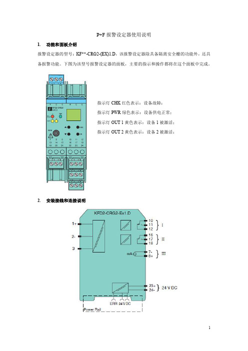
P+F报警设定器使用说明1.功能和面板介绍报警设定器的型号:KF**-CRG2-(EX)1.D,该报警设定器除具备隔离安全栅的功能外,还具备报警功能。
下图为该型号报警设定器的面板,主要的指示和操作都将在这个面板中完成。
指示灯CHK红色表示:设备故障;指示灯PWR绿色表示:设备供电正常;指示灯OUT1黄色表示:设备1被激活;指示灯OUT2黄色表示:设备2被激活;2.安装接线和连接说明上图为该报警设定器的侧面图形,在安装过程中,现场过来的4-20mA信号接在左侧“1-3”端子上,如果现场为配电信号则接在1,3端子上(1+、3-),如果现场为不配电信号则接在2,3端子上(3+、2-)。
图形的右侧有四个区域,其中23,24端子(23+、24-)给报警器提供24V电源;III区的7,8端子(8+、7-)去DCS系统柜相应的端子板上;I、II区则是输出去ESD的两个DI信号。
信号线分别接在10,11(11+、10-)以及16,17端子(17+、16-)。
I、II区对应于OUT1和OUT2指示灯。
因为一个变送器对应的信号可能存在高报(低报)或者高高报(低低报)两个报警限,所以有两个区,也对应有两个设备被激活的情况。
3.参数设置在报警设定器参数设置过程中,面板上有四个重要的按钮:“UP、DOWN、ESC、OK”。
同时摁住“OK”与“ESC”长达一秒,将进入参数设置的主菜单。
主菜单内有:输入(INPUT),输出(OUTPUT),单位(UNIT),服务(SERVICE)四个可操作项,这里只需要设置输入、输出以及单位即可。
通过“UP”或“DOWN”按钮,选择“UNIT”选项,点击“OK”,则进入单位设置,选择“4-20mA”,点击“OK”,完成单位的设置。
“INPUT”中存在一个线性检测“Line monitor”,点击“OK”,进行设置。
通过改变“LB”、“SC”可以对短路和断路进行检测。
如果LB选为ON,当输入信号小于0.2mA时,表示断路;如果SC选为ON,当输入信号大于22mA时,表示短路。
(整理)P+F说明及样品选型.

P+F安全栅及现场总线产品德国Pepperl+Fuchs公司成立于1945年。
1958年,P+F发明的世界首例本安型接近开关及与之世界的隔离式安全栅使工业防爆应用领域发生了全新的变革。
如今,P+F公司已发展成为世界上最大、最有经验的本安接口生产商。
其安全栅品种之丰富、处理特殊应用难题之能力一直处于世界领先地位。
其产品应用遍及石油、天然气、化工、石化、医药等存在易燃易爆危险场所的工业领域。
P+F积极推动本质安全技术面向现场总线时代的新变革。
P+F远程I/O型隔离栅RPI和本安型远程I/O系统IS-RPI已经开始对本安接口的应用产生深远的影响。
P+F的FieldConnex现场总线产品家族包含了将现场总线主机与现场仪表相连接的全套配件产品,包括各种网桥、现场总线配电器、现场总线中继器、现场总线I/O模盒、接线盒、现场总线安全栅、快速接插件等现场总线产品,更使本安防爆的现场总线全面进入实用阶段。
P+F公司的产品不仅符合德国、欧洲和国际(IEC)标准,其专业化的研究和开发工作,还曾经并继续为这些标准的制定提供依据。
P+F公司的所有生产和开发机构均获得ISO9001质量保证体系认证。
其产品还获得包括美国(FM)、中国(NEPSI)等世界诸多国家的防爆认证。
为确保完善的就近服务,P+F公司的过程自动化部(PA)和工厂自动化部(FA)在世界各主要国家和地区设立子公司和办事处。
在中国,P+F公司在北京、上海设有代表处和子公司,并在广州等全国各主要大城市设有办事机构。
P+F公司不仅仅是防爆技术专家,其经验和创造力还从其产品本身延伸至系统配套方面。
本样本将详述P+F齐纳栅、隔离栅与DCS和ESD控制系统配合的典型方案,并提供现场总线的配电、防爆和连接的典型方案。
P+F公司备有安全栅产品的详细的原版书面样本和CD-ROM样本及多种应用指南。
P+F 隔离栅的优势:轨道供电大部分隔离栅需要供电.当隔离栅使用数量较大时,给隔离栅配电不是一件轻松的工作.为了简化隔离栅的配电,P+F公司发明了轨道供电方式。
p+f转速安全栅组态
p+f转速安全栅组态P+F转速安全栅组态是指对P+F(Pepperl+Fuchs)品牌的转速安全栅进行配置和设置的过程。
转速安全栅是一种安全设备,用于监测旋转机械设备的转速,以确保工作环境的安全性。
在进行P+F转速安全栅的组态时,需要考虑以下几个方面:1. 安全栅的类型选择,根据具体的应用需求和安全要求,选择适合的P+F转速安全栅型号。
P+F提供了多种不同的转速安全栅,包括编码器、霍尔效应传感器等。
2. 连接方式,确定如何将P+F转速安全栅与控制系统连接起来。
通常,可以通过电缆连接或者总线接口来实现与控制系统的通信。
3. 参数设置,根据实际情况,设置P+F转速安全栅的相关参数,如转速范围、报警阈值、响应时间等。
这些参数的设置应该根据具体的工作环境和安全要求进行调整。
4. 安全级别配置,根据安全标准和要求,配置P+F转速安全栅的安全级别。
安全级别通常包括PL(Performance Level)和SIL (Safety Integrity Level),根据不同的标准和要求选择合适的级别。
5. 故障诊断和报警设置,配置P+F转速安全栅的故障诊断功能和报警设置,以便及时发现设备故障或异常情况,并采取相应的措施。
6. 安全栅的布置和安装,根据安全要求和工作环境,将P+F转速安全栅正确地布置和安装在旋转机械设备上。
确保安全栅能够有效地监测转速,并及时触发安全停机或报警。
总之,P+F转速安全栅组态需要综合考虑设备类型、连接方式、参数设置、安全级别、故障诊断和报警设置以及安装布置等多个方面,以确保转速安全栅能够正确运行并保障工作环境的安全性。
P+F 安全珊Hart管理

eexcellence in dependable automationFMEDA including SFF determinationand PFD calculationProject:HART multiplexer KFD2-HMM-16 together with KFD0-HMS-16 and 2700 HART Signal MultiplexerCustomer:Pepperl+Fuchs GmbHMannheimGermanyContract No.: P+F 02/4-11Report No.: P+F 02/4-11 R006Version V1, Revision R1.2, July 2002Stephan AschenbrennerCONFIDENTIAL INFORMATIONManagement summaryThis report summarizes the results of the analysis carried out on the HART multiplexerKFD2-HMM-16 together with KFD0-HMS-16 and the 2700 HART Signal Multiplexer.The assessment does not contain an evaluation of the correct functioning of the HARTmultiplexer but a statement about the interference freeness on the safety related 4..20mAloop when used for HART communication with regard to the suitability in part for Safety Instrumented System (SIS) usage in a particular Safety Integrity Level (SIL).The failure rates are based on the Siemens standard SN 29500.According to table 2 of IEC 61508-1 the average PFD for systems operating in low demandmode has to be ≥10-4 to < 10-3 for SIL 3 safety functions and ≥10-3 to < 10-2 for SIL 2 safetyfunctions. However, as the modules under consideration are only one part of an entire safetyfunction they should not claim more than 10% of this range, i.e. they should be better than orequal to 10-4 for SIL 3 and better than or equal to 10-3 for SIL 2.The modules under evaluation can be considered to be Type B components. However, the components that can contribute to a disturbance of the safety system are considered to be TypeA components.For Type A components the SFF has to fulfill the requirements as stated in table 2 ofIEC 61508-2 which are the following:Hardware fault tolerance (HFT)0 1 2 SIL 2 60% ≤ SFF < 90% SFF < 60%SIL 3 90% ≤ SFF < 99% 60% ≤ SFF < 90% SFF < 60%The following tables show under which conditions the critical components of the two modulesthat can contribute to a disturbance of the safety system fulfill this requirement (considering onlyone communication line being part of the safety function).Table 1: KFD2-HMM-16 together with KFD0-HMS-16 without additional module interfaceT[Proof] = 1 year T[Proof] = 5 years T[Proof] = 10 yearsPFD AVG = 1.23E-06PFD AVG = 6.13E-06PFD AVG = 1.23E-05than 10% of this range, i.e. to be better than or equal to 10-3. The PFD values even fulfill the requirements of higher SILs but the system does only fulfill the architectural constraints requirements (HFT/SFF) for SIL 2 which are set by table 2 of IEC 61508-2 for type A components having a hardware fault tolerance of 0.If the HART multiplexer KFD2-HMM-16 and KFD0-HMS-16 are used together with the module interface as described in section 4.1 then two de-coupling capacitors have to fail to bring the (sub)system into a dangerous state. This corresponds to a hardware fault tolerance of 1.Table 2: KFD2-HMM-16 together with KFD0-HMS-16 with additional module interface T[Proof] = 1 year T[Proof] = 5 years T[Proof] = 10 yearsPFD AVG = 6.13E-08PFD AVG = 3.07E-07PFD AVG = 6.13E-07than 10% of this range, i.e. to be better than or equal to 10-4. The PFD values even fulfill the requirements of a higher SIL but the system does only fulfill the architectural constraints requirements (HFT/SFF) for SIL 3 which are set by table 2 of IEC 61508-2 for type A components having a hardware fault tolerance of 1.Table 3: 2700 HART Signal MultiplexerT[Proof] = 1 year T[Proof] = 5 years T[Proof] = 10 yearsPFD AVG = 2.50E-07PFD AVG = 1.25E-06PFD AVG = 2.50E-06than 10% of this range, i.e. to be better than or equal to 10-4. The PFD values even fulfill the requirements of higher SILs but the system does only fulfill the architectural constraints requirements (HFT/SFF) for SIL 3 which are set by table 2 of IEC 61508-2 for type A components having a hardware fault tolerance of 1.The calculations are based on the assumption that the HART multiplexer are mounted in an environment that is IP 54 compliant (e.g. housing, control cabinet or control room).Table of ContentsManagement summary (2)1Purpose and Scope (5)2Project management (5)2.1Roles of the parties involved (5)2.2Standards / Literature used (5)2.3Reference documents (6)2.3.1Documentation provided by the customer (6)2.3.2Documentation generated by (6)3Description of the HART communication (7)4Description of the analyzed modules (8)4.1KFD2-HMM-16 and KFD0-HMS-16 (8)4.22700 HART Signal Multiplexer (11)5Failure Modes, Effects, and Diagnostics Analysis (12)5.1Description of the failure categories (12)5.2Methodology – FMEDA, Failure rates (12)5.2.1FMEDA (12)5.2.2Failure rates (12)5.2.3Assumption (13)6Results of the assessment (13)6.1KFD2-HMM-16 and KFD0-HMS-16 (15)6.22700 HART Signal Multiplexer (17)7Terms and Definitions (19)8Status of the document (20)8.1Liability (20)8.2Releases (20)8.3Release Signatures (20)1 Purpose and ScopeThis report shall describe the results of the FMEDAs carried out on the HART multiplexer KFD2-HMM-16 together with KFD0-HMS-16 and the 2700 HART Signal Multiplexer.It shall be shown that the HART multiplexer do not electrically interfere with the connected safety related system when using the 4..20mA loop for the HART communication.It shall be assessed whether these modules meet the Probability of Failure on Demand (PFD) requirements for SIL 2 / SIL 3 sub-systems according to IEC 61508 with regard to the interference freeness on the safety related 4..20mA loop.The assessment does neither consider any calculations necessary for proving intrinsic safety nor an evaluation of the correct functioning of the HART multiplexer.Pepperl+Fuchs GmbH contracted in May 2002 with the FMEDA and PFD calculation of the above mentioned modules.2 Project management2.1 Roles of the parties involvedPepperl+Fuchs Manufacturer of the HART multiplexer. Did the FMEDAs together with the determination of the Safe Failure Fraction (SFF) and calculated the Probability of Failure on Demand (PFD)using Markov models.2.2 Standards / Literature usedThe services delivered by were performed based on the following standards / literature.[N1] IEC 61508-2:1999 Functional Safety of Electrical/Electronic/ProgrammableElectronic Safety-Related Systems[N2] ISBN: 0471133019 Electronic Components: Selection and Application Guidelinesby Victor MeeldijkJohn Wiley & Sons[N3] FMD-91, RAC 1991 Failure Mode / Mechanism Distributions[N4] SN 29500 Failure rates of components2.3 Reference documents2.3.1 Documentation provided by the customer[D1] DL0799, DL0800 of 21.04.01 Circuit diagram for KFD2-HMM-16 and KFD0-HMS-16 [D2] 107905 Bill of material for KFD2-HMM-16[D3] ES-984240/1-A1 of 18.11.99 Circuit diagram for 2700 HART Signal Multiplexer(Mother Board Multiplexer / Interface Circuit)[D4] CL-984240/1-A4 of 24.03.99 Bill of material for 2700 HART Signal Multiplexer (MotherBoard)[D5] ES-984240/2-A1 of 18.11.99 Circuit diagram for 2700 HART Signal Multiplexer(µProcessor Board)[D6] CL-984240/2-A3 of 16.03.99 Bill of material for 2700 HART Signal Multiplexer(µProcessor Board)[D7] Datasheet metallized polyester capacitor WIMA MKS 2 2.3.2 Documentation generated by [R1] FMEDA KFD2-HMM-16 V1 R1.0 – Analysis of 24.06.02[R2] FMEDA KFD2-HMM-16 V1 R1.0 – Results of 24.06.02[R3] FMEDA MUX 2700 V1 R1.0 – Analysis of 24.06.02[R4] FMEDA MUX 2700 V1 R1.0 – Results of 24.06.023 Description of the HART communicationThe HART1 protocol is supported by many conventional 4..20 mA field devices, which thus enable digital communication for configuration and servicing purposes. Many device parameters and also the measured values themselves can thus be digitally transferred to and from the device. This digital communication runs in parallel with the 4..20 mA signal on the same cable. This is possible through a current modulation, which is superimposed on the user signal.Figure 1: Modulated HART signalHART is a master-slave protocol: A field device does only respond when requested (except in "Burst mode").The message duration is several hundred milliseconds, so that between two and three messages can be transferred per second.On HART, there are three groups of commands:• The "Universal" commands; these must be supported by all field devices;• The "Common practice" commands; these are pre-defined commands, suitable for many field devices, which, if they are supported by the device, must be implemented in the pre-defined form;• Device-specific commands; these are commands, which are particularly suitable for this field device.1 HART = Highway Addressable Remote Transducer4 Description of the analyzed modulesIn safety-related applications the HART communication is used to provide additional (non safety-related) information about statuses and reading, allow for better preventive maintenance and thus improve the integrity of the field instrumentation.For this purpose the HART multiplexer have to be directly connected to the field wiring of the respective safety-related system (see Figure 2).Figure 2: Connection of the HART multiplexer with the safety-related system4.1 KFD2-HMM-16 and KFD0-HMS-16The HART multiplexer KFD2-HMM-16 can operate up to 256 analog transmitters. The built-in slave unit operates the first 16 loops, and a maximum of further 15 KFD0-HMS-16 slaves can be connected.The power supply (24 VDC nominal voltage) is provided via the power rail or terminals 17 and 18. The optional slave units or the RPI control module are connected with the master via a 14-core flat cable. Its connector is placed on the same housing side as the terminals for the RS 485 interface and the voltage supply.The analog signals for each unit are connected separately via a 26-core cable. 16 leads are provided for the HART signals of the analog instrument circuits, the other 10 are connected to ground.The minimum load resistance of the analog instrument circuits is 230 Ω (min. load resistance in accordance with the HART specification), the max. load resistance is 500 Ω. Load resistances of up to 1000 Ω are possible, however, resistance values greater than 500 Ω can interfere with the HART communication.A process control system or a PC can be connected via a RS 485 interface (terminals 13, 14 and 15). Up to 31 KFD2-HMM-16 can be operated on one RS 485 interface. Terminals 19, 20 and 21 can be used to connect additional stations to the RS 485 interface. The DIP-switch on the housing front is for the setting of the RS 485 address and the baud rate.Figure 3: Block diagram of KFD2-HMM-1626 pin connectorfor up to16 analog signal sources 14 pin connector for up to 15 KFD0-HMS-16 devicesFigure 4: Block diagram of KFD2-HMS-16The HART multiplexer KFD2-HMM-16 (KFD0-HMS-16) has only one de-coupling capacitor for each analog signal as can be seen in Figure 3 and Figure 4, but can be connected to a module interface as shown in Figure 5 to also have the ground de-coupled by a second capacitor. Figure 5: Block diagram HART multiplexer with module interface for loop 1 and 24.2 2700 HART Signal MultiplexerThe Mux2700 HART Multiplexer provides 32 signal channels for connection to “smart” transmitters or control devices supporting digital communication according to the HART standard.Two Decoupling Capacitors are provided, one for each signal connection.Both + Ve (positive) & - Ve (negative) signal wires are therefore decoupled from DC signal. Only the high frequency digital HART protocol signal passes through to the internal Multiplexer circuitry.It acts as a gateway between a workstation - typically a PC - and the field instrumentation.Each Mux2700 is networked simply by connecting the high-speed RS485 output in multidrop configuration. The Mux2700 interrogates each field device, under the supervision of the workstation, retrieving information for storage in its internal database, which can then be accessed at ease.Figure 6: Block diagram of 2700 HART Signal Multiplexer5 Failure Modes, Effects, and Diagnostics Analysis5.1 Description of the failure categoriesThe fail-safe state is defined as the HART multiplexer is not communicating.Failures are categorized and defined as follows:A safe failure (S) is defined as a single failure that causes the HART multiplexer not to communicate.A dangerous failure (D) is defined as a single failure that disturbs the safety system connected to the HART multiplexer.A “don't care” failure (#) is defined as a single failure of a component that is part of the safety function but has no effect on the safety function of the module / (sub)system.5.2 Methodology – FMEDA, Failure rates5.2.1 FMEDAA Failure Modes and Effects Analysis (FMEA) is a systematic way to identify and evaluate the effects of different component failure modes, to determine what could eliminate or reduce the change of failure, and to document the system in consideration.An FMEDA (Failure Mode Effect and Diagnostic Analysis) is an FMEA extension. It combines standard FMEA techniques with extension to identify online diagnostics techniques and the failure modes relevant to safety instrumented system design. It is a technique recommended to generate failure rates for each important category (safe detected, safe undetected, dangerous detected, dangerous undetected, fail high, fail low) in the safety models. The format for the FMEDA is an extension of the standard from MIL STD 1629A, Failure Modes and Effects Analysis.5.2.2 Failure ratesThe failure rate data used by in this FMEDA are from the Siemens SN 29500 failure rate database. The rates were chosen in a way that is appropriate for safety integrity level verification calculations. It is expected that actual field failure results with average environmental stress will be superior to the results predicted by these numbers.The user of these numbers is responsible for determining their applicability to any particular environment. Accurate plant specific data is preferable to general industry average data. Industrial plant sites with high levels of stress must use failure rate data that is adjusted to a higher value to account for the specific conditions of the plant.5.2.3 AssumptionThe following assumptions have been made during the Failure Modes, Effects, and Diagnostic Analysis of the HART multiplexer.• Failure rates are constant, wear out mechanisms are not included.• Propagation of failures is not relevant.• All component failure modes are known.• The repair time after a safe failure is 8 hours.• The average temperature over a long period of time is 40°C.• The stress levels are average for an industrial environment.• All modules are operated in the low demand mode of operation.• Only one communication line is considered to be part of the safety function.6 Results of the assessment did the FMEDAs supported by Pepperl+Fuchs.The analysis has shown that only a couple of components of the HART multiplexer can be found where potentially dangerous failure exist. All other component failures can only lead to the defined safe state but can never disturb the connected safety-related system. The following critical points were identified:1. Short circuits (to ground, to power or between each other) of the signal lines from theinterconnection terminal to the field side of the de-coupling capacitors;2. Short circuit of the de-coupling capacitor.For the calculation of the Safe Failure Fraction (SFF) the following has to be noted:λtotal consists of the sum of all component failure rates. This means:λtotal = λsafe + λdangerous + λdon’t care2SFF = 1 – λdu / λtotalFor the FMEDAs the following failure modes and below mentioned distributions were used. Capacitor fixed plastic (in accordance with [N3])Failure Mode Distribution (in %)Short 40 Open 42 Change in value 182 These are all failures that have no impact on the safety function. The behavior of the system is neither dangerous nor safe.Capacitor Al-ELKO (in accordance with [N3]) Failure ModeDistribution (in %)Short 38 Open 31 Seal failure31For the calculation of the PFD the following Markov models for a 1oo1 and 1oo2 architecture were used. As there are no explicit on-line diagnostics, no state “dd” – dangerous detected is required. As after a complete proof all states are going back to the OK state no proof rate is shown in the Markov models but included in the calculation.The proof time was changed using the Microsoft® Excel 2000 based FMEDA tool of as a simulation tool. The results are documented in the following sections.Figure 7: Markov model for a 1oo1 architectureAbbreviations: d The system has failed dangerous s The system has failed safe λd Failure rate of dangerous failures λs Failure rate of safe failures βCommon cause factor (set to 5%)T Repair Repair time τRepair Repair rate (1 / T Repair )Figure 8: Markov model for a 1oo2 architecture6.1 KFD2-HMM-16 and KFD0-HMS-16Item 1. of the critical points identified in section 6 can be excluded according to draft IEC 60947-5-3 A.1.2 if:• The HART multiplexer are mounted in a housing of minimum IP 54• The base material used is according to IEC 60249, the design and use of the printed board is according to IEC 60326 T3 and the creepage distances and clearances are designed according to IEC 60664-1 (1992) with pollution degree 2 / installation category III, or• The printed side(s) are coated with an insulation material in accordance to IEC 60664-3 (1992)Clearances and creepage distances according to IEC 60661-1 with pollution degree 2 / installation category II for a nominal voltage of 24 VDC are given in Table 4.Table 4: Clearances and creepage distances according to IEC 60661-1Clearances (table 2) Creepage distances (table 4) Printed wiring material 0,1 mm 0,04 mmAccording to Pepperl+Fuchs the base material used is according to IEC 60249 and the minimum creepage distances and clearances are 0,15 mm. This is considered to be sufficient as the interesting distances are part of an energy-consuming equipment supplied from fixed installation, i.e. installation category II. In addition the HART multiplexer is not a safety critical system itself but is connected to one. Thus there are no to special requirements with regard to reliability and availability (see section 2.2.2.1.1 of IEC 60664-1) and installation category III does not apply.Item 2. of the critical points identified in section 6 was analyzed in form of a FMEDA under the assumptions described in section 5.2.3 and 6.The following failure rates and SFF were calculated for the de-coupling capacitor:λtotal = 7,00E-10 1/hλsafe = 2,94E-10 1/hλdangerous = 2,80E-10 1/hλdon’t care = 1,26E-10 1/hSFF = 60,00% (HFT = 0)NOTE: As all faults of the additional electronic will either contribute to λsafe or λdon’t care with regard to the interference freeness on the 4..20mA signal the failure modes of the different components were not explicitly analyzed and are not part of the above mentioned failure rates.The PFD was calculated for three different proof times using the Markov model as described in Figure 7.T[Proof] = 1 year T[Proof] = 5 years T[Proof] = 10 yearsPFD AVG = 1.23E-06PFD AVG = 6.13E-06PFD AVG = 1.23E-05than 10% of this range, i.e. to be better than or equal to 10-3. The PFD values even fulfill the requirements of higher SILs but the system does only fulfill the architectural constraints requirements (HFT/SFF) for SIL 2 which are set by table 2 of IEC 61508-2 for type A components having a hardware fault tolerance of 0.The following figure shows the result of the PFD calculation for T[Proof] = 1 year.Figure 9: PFD for T[Proof] = 1 yearIf the HART multiplexer KFD2-HMM-16 and KFD0-HMS-16 are used together with the module interface as described in section 4.1 then two de-coupling capacitors have to fail to bring the (sub)system into a dangerous state. This corresponds to a hardware fault tolerance of 1.The PFD was calculated for three different proof times using the Markov model as described in Figure 8.T[Proof] = 1 year T[Proof] = 5 years T[Proof] = 10 yearsPFD AVG = 6.13E-08PFD AVG = 3.07E-07PFD AVG = 6.13E-07than 10% of this range, i.e. to be better than or equal to 10-4. The PFD values even fulfill the requirements of a higher SIL but the system does only fulfill the architectural constraints requirements (HFT/SFF) for SIL 3 which are set by table 2 of IEC 61508-2 for type A components having a hardware fault tolerance of 1.The following figure shows the result of the PFD calculation for T[Proof] = 1 year and β = 5% (maximum common cause factor for a logic sub-system according to IEC 61508-6).Figure 10: PFD for T[Proof] = 1 year and β = 5%6.2 2700 HART Signal MultiplexerItem 1. of the critical points identified in section 6 can be excluded according to draft IEC 60947-5-3 A.1.2 if:• The HART multiplexer are mounted in a housing of minimum IP 54• The base material used is according to IEC 60249, the design and use of the printed board is according to IEC 60326 T3 and the creepage distances and clearances are designed according to IEC 60664-1 (1992) with pollution degree 2 / installation category III, or• The printed side(s) are coated with an insulation material in accordance to IEC 60664-3 (1992)Clearances and creepage distances according to IEC 60661-1 with pollution degree 2 / installation category II for a nominal voltage of 24 VDC are given in Table 5.Table 5: Clearances and creepage distances according to IEC 60661-1Clearances (table 2) Creepage distances (table 4) Printed wiring material 0,1 mm 0,04 mmAccording to Pepperl+Fuchs the base material used is according to IEC 60249 and the minimum creepage distances and clearances are 0,25 mm. This is considered to be sufficient as the interesting distances are part of an energy-consuming equipment supplied from fixed installation, i.e. installation category II. In addition the HART multiplexer is not a safety critical system itself but is connected to one. Thus there are no to special requirements with regard to reliability and availability (see section 2.2.2.1.1 of IEC 60664-1) and installation category III does not apply.Item 2. of the critical points identified in section 6 was analyzed in form of a FMEDA under the assumptions described in section 5.2.3 and 6.The following failure rates and SFF were calculated for the two de-coupling capacitors: λtotal = 3,70E-09 1/h λsafe = 1,22E-09 1/h λdangerous = 1,42E-09 1/h λdon’t care = 1,06E-09 1/h SFF = 61,62% (HFT = 1)NOTE: As all faults of the additional electronic will either contribute to λsafe or λdon’t care with regard to the interference freeness on the 4..20mA signal the failure modes of the different components were not explicitly analyzed and are not part of the above mentioned failure rates. As two de-coupling capacitors have to fail to bring the (sub)system into a dangerous state a hardware fault tolerance of 1 is considered.The PFD was calculated based on the failure rate of the Al-ELKO as a worst case assumption for three different proof times using the Markov model as described in Figure 8.T[Proof] = 1 yearT[Proof] = 5 yearsT[Proof] = 10 yearsPFD AVG = 2.50E-07PFD AVG = 1.25E-06PFD AVG = 2.50E-06than 10% of this range, i.e. to be better than or equal to 10-4. The PFD values even fulfill the requirements of a higher SIL but the system does only fulfill the architectural constraints requirements (HFT/SFF) for SIL 3 which are set by table 2 of IEC 61508-2 for type A components having a hardware fault tolerance of 1.The following figure shows the result of the PFD calculation for T[Proof] = 1 year and β = 5% (maximum common cause factor for a logic sub-system according to IEC 61508-6).Figure 11: PFD for T[Proof] = 1 year and β= 5%7 Terms and DefinitionsFMEDA Failure Mode Effect and Diagnostic AnalysisHFT Hardware Fault ToleranceLow demand mode Mode, where the frequency of demands for operation made on a safety-related system is no greater than one per year and no greater than twicethe proof test frequency.λtotal Total failure rate λ (overall failure rate of all components)λsafe Failure rate λ of all safe failuresλdangerous Failure rate λ of all dangerous failuresλdu Failure rate λ of dangerous undetected failuresPFD Probability of Failure on DemandPFD AVG Average Probability of Failure on DemandSFF Safe Failure Fraction summarizes the fraction of failures, which lead to a safe state and the fraction of failures which will be detected bydiagnostic measures and lead to a defined safety action.SIF Safety Instrumented FunctionSIL Safety Integrity LevelSIS Safety Instrumented System8 Status of the document8.1 Liability prepares FMEDA reports based on methods advocated in International standards. Failure rates are obtained from a collection of industrial databases. accepts no liability whatsoever for the use of these numbers or for the correctness of the standards on which the general calculation methods are based.8.2 ReleasesVersion: V1Revision: R1.2Version History: V0, R1.0: Initial version, June 19, 2002V0, R1.1: Failure rates for the de-coupling capacitors of the MUX 2700corrected; section 2.3.2 completed; failure modes of Al-ELKO insection 6 added; June 24, 2002V1, R1.0: Comments after review integrated, June 27, 2002V1, R1.1: Management summary corrected; section “Purpose and Scope”modified, June 28, 2002V1, R1.2: Management summary changed; section “Purpose and Scope”modified, July 3, 2002AschenbrennerAuthors: StephanReview: V0, R1.0: Werner Bansemir (P+F), June 24, 2002V0, R1.1: Peter Müller (), June 26, 2002Release status: released to Pepperl+Fuchs8.3 Release SignaturesDipl.-Ing. (Univ.) Stephan Aschenbrenner, Senior Project ManagerDipl.-Ing. (Univ.) Rainer Faller, Principal Partner。
常用安全栅介绍及P+F温变设置(江朝均160601)

接近开关简介
接近开关又称无触点行程开关。它能在一定的距离(几毫 米至几十毫米)内检测有无物体靠近。当物体与其接近 到设定距离时,就可以发出“动作”信号。
接近开关的核心部分是“感辨头”,它对正在接近的物体 有很高的感辨能力。
性能特点
接近开关与被测物不接触、不会产生机械磨损和疲劳损伤、 工作寿命长、响应快、无触点、无火花、无噪声、防潮、防 尘、防爆性能较好、输出信号负载能力强、体积小、安装、 调整方便; 缺点是 触点容量较小、输出短路时易烧毁。
开路故障,并将故障以干接点信号送入DCS或者PLC。 适合此应用的DI隔离栅有: KFD2-SR2-EX2.2S KFD2-SRA-EX4 KFD2-ST2-EX1.LB KFD2-ST2-EX2
KFD2-SOT2-EX2 KFD2-DU-EX1.D 适合此应用的DO隔离栅有: KFD2-SL2-EX1 KFD2-SL2-EX2 此应用是通过电源模块7和10端子输出一个干接点到DCS或者PLC系统。(继电
KFD2-UT-EX1-1单通道有源1-5V进控制系统。 (热阻热偶输入,热偶信号需配 置冷端补偿器)
KFD2-SR2-EX1.W 数字量输入,接受干接点。单通道 KFD2-SR2-EX1.W .LB数字量输入,接受干接点,单通道。一进二出。 KFD2-EB2 电源模块。每台配电容量为4A。最多可为49台导轨安全栅供电。一
控制引爆源
人为地消除引爆源,既消除足以引爆的火花,又消除足以引爆的仪表表面温升 。就是利用安全栅技术,将提供给现场仪表的电能量限制在既不能产生足以引爆 的火花,又不能产生足以引爆仪表表面温升的安全范围内。按照国际标准和国内 标准,当安全栅安全区一侧所接设备发生任何故障(不超过250V电压)时,本 质防爆方法确保现场的防爆安全。典型代表:EX i。EX ia级本质安全设备在正 常工作、发生一个故障、发生两个故障时均不能点燃爆炸性气体混合物。显而易 见,本质安全法是最可靠安全的防爆方法。
p+f安全栅

P+F安全栅的应用及选型过程中注意事项。
德国Pepperl+Fuchs公司成立于1945年。
1958年,P+F公司发明了世界首例本安型接近开关及与之世界的隔离式安全栅使工业防爆应用领域发生了全新的变革。
P+F安全栅有源隔离器与无源隔离器,齐纳式安全栅和隔离式安全栅。
德国Pepperl+Fuchs公司成立于1945年。
1958年,P+F公司发明了世界首例本安型接近开关及与之世界的隔离式安全栅使工业防爆应用领域发生了全新的变革。
P+F安全栅有源隔离器与无源隔离器,齐纳式安全栅和隔离式安全栅。
P+F安全栅齐纳齐纳式隔离式安全栅能与各种现场的一次仪表如:4-20mA的压力、温度、流量、电信号变送器;电器转换器、电气阀门定位器、各类热电偶、热电阻、开关量、报警器、脉冲信号等各种特殊仪表,组成本质安全防爆系统,用于现代化工业的自动化过程控制,广泛地用于石油化工、冶金、医药、船舶等领域。
可限制危险能量进入具爆炸性危险气体环境的可靠设备。
P+F安全栅结构与外型尺寸P+F安全栅采用两种不同的外型和安装尺寸,外壳由阻燃防弧塑料压制成型,整个安全栅电路以阻燃环氧树脂封装在壳体内,各端子间的爬电距离、电气间隙及材料的相对泄痕指数均符合GB 3836.4中的有关规定。
主要技术参数正常工作条件环境温度:-20ºC~+40ºC ;b.相对湿度:< 95% RH ; c. 大气压:80~110 Kpa ;P+F安全栅的参数确定全栅选型在安全栅的使用中比较关键,选择正确的安全栅是保证系统防爆的基础。
安全栅选型要保证以下两点:第一,要保证系统的工作正常,需要根据系统的参数,确定安全栅的参数,齐纳安全栅主要看工作电压,最高工作电压,端电阻等参数,隔离安全栅主要看可以达到的精度。
当然,无论齐纳安全栅还是隔离安全栅,要考虑的还后工作环境,如使用温度,湿度,还有安装方式是否便于现场安装等等。
第二,要根据需要防爆的区域,是0区,1区还是2区,来确定需要达到的防爆等级,最后可以确定是用ia级的还是ib级的安全栅。
光栅操作手册(P+F)
F A C T O R Y A U T O M A T I O N SLP/SLPC SLP/SLPCM 操作手册安全光栅With regard to the supply of products, the current issue of the following document is applicable: The General Terms of Delivery for Products and Services of the Electrical Industry,published by the Central Association of the Electrical Industry (Zentralverband Elektrotechnik und Elektroin-dustrie (ZVEI) e.V.)in its most recent version as well as the supplementary clause: "Expanded reservation of proprietorship"We at Pepperl+Fuchs/VISOLUX recognize a duty to make a contribution to the future.D a t e o f i s s u e 02/25/0238.3.4Test of error enable connection (RESET)...................................... 27SLP/SLPC 和 SLP/SLPCM 安全光栅目录章 页1 使用目的 ............................................ 62 产品描述 ............................................ 62.1 系统特点 .................................................... 62.2 工作原理 .................................................... 72.3 原理框图 .................................................... 83 电气连接 ........................................... 103.1 SLPC(M)端子区 .............................................. 103.2 SLPC(M)连接器 .............................................. 123.3 Muting 灯连接 / 灯插座(仅对SLPCM...-L...) ................ 133.4 SLP发射器的连接............................................. 144 状态指示 ........................................... 155 工作模式 ........................................... 165.1 启动 / 重启锁(Restart).................................... 175.2 继电器监控.................................................. 175.3 Muting(SLPCM)............................................. 185.3.1 工作原理.................................................... 195.3.1.1 平行或连续Muting方式下对Muting传感器的评估......................... 195.3.1.2 时间窗口限制或保护光束限制Muting方式下的Muting监控 ......................... 205.3.2 Muting传感器................................................ 225.3.2 Muting指示灯................................................ 225.4 紧急Muting(仅对SLPCM)..................................... 226 光栅的安装 ......................................... 237 电气安装布置 ....................................... 258.2 反射镜的布置................................................ 268.1 调整保护光束................................................ 268 调试 ............................................... 268.3 功能测试.................................................... 278.3.1 NCSE检测能力测试............................................ 278.3.2 Muting功能测试(仅对SLPCM)................................. 278.3.3 启动/重启锁和启动能力测试................................... 278.3.5 继电器监控测试.............................................. 288.3.6 OSSD工作原则................................................ 28D a t e o f i s s u e 02/25/02416.1Construction and equipping of safety equipment......................... 4416.2Use and installation of protective equipment................................ 44Please note!This instruction manual contains instruction explaining the intended use of the product and serves as a protection from danger. It must be read and observed by all persons who make use of, care for, maintain and monitor this product. This pro-duct can only accomplish the tasks for which it is intended if it is used, cared for,maintained and monitored in accordance with the instructions of Pepperl+Fuchs/Visolux.The warranty undertaken by Pepperl+Fuchs/Visolux for this product becomes null and void if it is not used, cared for, maintained and monitored in accordance with the instructions of Pepperl+Fuchs/Visolux.Before this product is used, an evaluation must be undertaken to determine whe-SLP/SLPC 和 SLP/SLPCM 安全光栅9 定期检查 ........................................... 2810 故障诊断 ........................................... 2911 技术参数 ........................................... 3011.1 电气参数及特性.............................................. 3011.2 外形尺寸.................................................... 3212 附件 ............................................... 3412.1 SLP安装支架................................................. 3412.2 SLP反射镜................................................... 3512.3 SLP保护镜................................................... 3612.4 SLP保护镜固定架............................................. 3612.5 SLP辅助对齐瞄准器........................................... 3612.6 SLP激光辅助对齐工具......................................... 3712.7 电缆连接器.................................................. 3712.8 电缆扎带.................................................... 3713 订购信息 ........................................... 3814 电路图示例 ......................................... 4015 术语表 ............................................. 4316 标准 ............................................... 4417 证书 ............................................... 45D a t e o f i s s u e 02/25/025ther it is suitable for the application at hand. Selection and use are not subject to influence on the part of Pepperl+Fuchs/Visolux. Our liability is thus restricted to consistent quality of the product.The product must be monitored and maintained by competent professionals. A re-cord must be kept of the results of inspections and maintenance tasks. Only ori-ginal Pepperl+Fuchs/Visolux parts must be used for repair jobs.The operator is not permitted to make changes to the machines or components thereof, or make use of defective or incomplete machines or components. Repairs to machines or components must only be performed by Pepperl+Fuchs/Visolux or by authorized workshops. Such workshops are responsible for acquiring the latest technical information about machines and components from Pepperl+Fuchs/Viso-lux.Repair tasks made on the product that are not performed by Pepperl+Fuchs/Viso-lux are not subject to influence on the part of Pepperl+Fuchs/Visolux.Our liability is thus limited to repair tasks that are performed by Pepperl+Fuchs/Visolux.The preceding information does not change information regarding warranty and liability in the terms and conditions of sale and delivery of Pepperl+Fuchs.This device contains sub-assemblies that are electrostatically sensitive. Only competent professional staff members are permitted to open the device for main-tenance and repair jobs. The sub-assemblies must be protected against the dan-ger of electrostatic discharge caused by touching them without protection. In the event that basic components are destroyed as a result of electrostatic discharge,the warranty becomes null and void!Subject to technical modifications.System of symbolsSymbols are used in this manual to provide information on operating and working with the safety light grid SLPC(M) and on safety related to it. The meaning of theseSLP/SLPC 和 SLP/SLPCM 安全光栅D a t e o f i s s u e 02/25/026This system mustonly be used in accordance with no-contact safety equipment (NCSE) to secure hazardous areas or ranges from being accessed. The operating modes that are set make it possible among other things to operate the SLPCM with the mutingThe SLP/SLPC(M) system is NCSE of Type 4 (EN 61496-1 or IEC 61496-1) or Category 4 (EN 954-1). The special feature of the SLPC(M) is the adjustable ope-rating modes Startup / restart lock and Relay monitor.••••••••••••SLP/SLPC 和 SLP/SLPCM 安全光栅1 使用目的使用目的2 产品描述2.1 系统特点SLP/SLPC(M)系列安全光栅包括两个部分:带处理单元的接收器SLPC或SLPCM以及与之匹配的安全光栅发射器SLP..-T。
P F倍加福安全栅分类使用原理及选用

P+F倍加福安全栅分类使用原理及选用行业工程师与大家分享P+F倍加福倍加福安全栅分类使用原理。
如何选择P+F倍加福倍加福安全栅,使用P+F倍加福倍加福安全栅时应该注意哪些事项,P+F倍加福安全栅安装注意事项,P+F倍加福倍加福安全栅如何维护?东莞市巴菲特专业为您提供P+F倍加福倍加福安全栅相关问题解答。
除了要选择合适的安全栅外,使用P+F倍加福安全栅的时候要注意以下几个方面:第一,要注意线缆和现场设备的容抗和感抗,本安防爆是系统防爆,除了安全栅需要达到所需的防爆等级外,线缆和现场设备的蓄能也是一个关键问题。
特别是在参量认证替代系统认证后,工程商尤其要注意这个问题。
第二,要注意本安接地,齐纳安全栅需要本安接地,接地电阻应小于1。
第三,本安线缆与非本安线缆应分开敷设在不同的线槽里。
并应有明显标识。
第四,更换时应注意断电。
倍加福安全栅又称安全限能器,是本安系统中的重要组成部分。
倍加福安全栅主要有P+F齐纳式安全栅和P+f隔离式安全栅两大类。
倍加福齐纳式安全栅的核心元件为齐纳二极管,限流电阻及快速熔断丝。
P+f隔离式安全栅信号和电源隔离单元、信号处理单元组成。
倍加福安全栅的主要功能为限流限压,保证现场仪表可得到的能量在安全范围内。
倍加福安全栅是介于现场设备与控制室设备之间的一个限能电路,用来把控制室供给现场仪表的电能量限制在既不能产生足以引爆危险气体的火花,又不能产生足以引爆危险气体的仪表表面温度,从而消除了引爆源。
在选择倍加福安全栅时必须考虑其型号与现场仪表类型相适应,还须考虑倍加福安全栅与本质安全仪表要求相兼容及形成的本安系统中阻抗匹配的问题。
我国采用“回路认证”这种方式认证本安系统,即根据危险环境使用仪表的联合取证情况,选择已与其联合取证的倍加福安全栅,一经联合取证,现场仪表与倍加福安全栅便固定组合构成本安系统。
实践中,这种方式对倍加福安全栅和现场仪表的选择有很大的局限性。
广泛采用是进年来逐渐形成的一种本质安全认证技术,即“参量认证”。
P+F安全栅培训ppt课件

中国国家级石油和化学工业电气产品防爆质量监督检验中心 (PCEC)是中华人民共和国地区监督生产安全防爆产品的权威机构, 对本安型安全栅产品有着严格、科学、详细的规定,只有通过该监 督站认证的企业及其所开发生产的产品才具备符合标准的安全性能, 否则可能会给使用方的设备、人员和生产造成无可估量的损害。
24
25
无源隔离栅和sink信号
26
其它类安全栅
27
安全供电方式
外部供电
导轨供电
28
29
齐纳安全栅
AI型30齐Fra bibliotek安全栅AO型
31
32
33
34
35
36
37
38
39
40
41
42
43
44
45
46
47
48
49
50
51
P+F安全栅 组态
P+F安全栅的组态主要指对温变式安全栅的组态 ,下面我们大概了解一下,温变式安全栅组态软 件的安装与一般组态。
P+F安全栅的基础知识 与接线组态、故障判断
及处理方法
1
主要内容
1.安全栅的简介 2.齐纳式安全栅 3.隔离式安全栅 4.P+F安全栅名称含义 5.常用的隔离式P+F安全栅 5.常用齐纳安全栅 6.温变式安全栅的组态 7.安全栅的常见故障及处理方法
2
安全栅简介
本安型安全栅介绍: 本安型安全栅应用在本安防爆系统的设计中,它是安装于安全
P+F安全栅说明书(中文)

KF 系列隔离栅致力与在完成本安防爆的 基本功能的同时,帮助用户获得更多的信息。 • 全面支持模拟量输入输出回路的智能通讯。该
系列隔离栅支持目前市场上应用的所有智能通 讯协议,如 HART、Brain、Foxcom、DE, 等等。 • 在支持 HART 智能通讯方面,KF 系列隔离栅 设计得几乎无微不至。不仅普通的单通道 AI 和 AO 型号支持 HART,双通道 AI 和 AO、一 进二出 AI 同样支持 HART。不仅支持二线制 変送器的 HART 通讯,还支持 4 线制変送器 的 HART 通讯。 • KF 系列隔离栅还细致地照顾到用户在全面应 用智能通讯时地一些特殊问题。比如,用户有 时希望支持 HART 通讯地隔离栅能兼容非智 能仪表。又如,用户希望在 DCS 系统尚未连
有源或无源 4-20mA 信号,或 1-5V 信号。
单通道 是 SIL2 有源 4-20mA 信号。智能型,
双通道 是 SIL2 支持 HART。
一进二出 是 SIL2
KFD2-STC4-Ex1-Y122583 单通道 是 SIL2 无源 4-20mA 信号。智能型,
KFD2-STC4-Ex1.2O-Y122582 一进二出 是 SIL2 支持 HART。
AO,
KCD2-SCD-Ex1
单通道 是 SIL2 4-20mA 信号。兼容智能/非智
4-20mA 驱动电气转 换器或电气 阀门定位器
KFD2-SCD-Ex1.LK KFD2-SCD2-Ex2.LK KFD2-CD-Ex1.32 KFD2-CD2-Ex2
单通道 双通道 单通道 双通道
是 SIL2 能仪表。带线路故障检测功 是 SIL2 能。 否 SIL2 4-20mA 信号。 否 SIL2 4-20mA 信号。
P+F安全栅组态说明

第七步、计算机、通讯电缆与设备连接成功后(通讯电缆的RX、TX 灯同时闪烁),右键点击“HiD2081或KF*-UT2-*FDT”的“load from device”选项,将 所连接设备的参数上传至计算机。
▪ 温度量程下限输入到“start value”对话框中,量程上限输入到“end value”对 话框中。
▪ 在“Charachteristic”中可选择输出的模式,我们推荐选择“4-20mA NE43”,便 于对线路进行监测。
▪ 在“error indication”中可设定现场回路断路/短路状态下,模块输出的电流值。 “upscale”表示跑大,“downscale”表示跑小。
▪ 如使用的是 KFD2-UT2-(EX)1, 则在“Analog input”项中选“Input 1”。 ▪ 如使用的是 KFD2-UT2-(EX)2,则: ▪ 实现双通道功能,“Analog Output 1”中的“Analog Input”选“input 1”; ▪ “Analog output 2”中“Analog input”选“input 2”; ▪ 实现一进二出功能,“Analog Output 1”中的“Analog Input”选“input 1”; ▪ “Analog output 2”中“Analog input”选“input 1”;
安装完成后,弹出如下窗口,即成功安装。
▪ 以上三个软件需正常安装,才能进行P+F安全栅组态, 即表示成功了一半。
第一步:将 K-ADP-USB 电缆插入 计算机USB 口后,在系统的 “设备管理器”中“通用串行总线控制器”会显示”K-ADPUSB-P2P”,如下图。
P+F安全栅KCD2-STC-EX1_AI说明书

18-11-05 15:26D a t e o f i s s u e 2018-11-05185535_e n g .x m lConnectionAssembly•1-channel isolated barrier •24 V DC supply (Power Rail)•Input for 2-wire SMART transmitters and current sources •Output for 4 mA ... 20 mA or 1 V ... 5 V •Sink or source mode •Housing width 12.5 mm•Up to SIL 2 acc.to IEC 61508FunctionThis isolated barrier is used for intrinsic safety applications.The device supplies 2-wire SMART transmitters in ahazardous area, and can also be used with 2-wire SMART current sources.It transfers the analog input signal to the safe area as an isolated current value.Digital signals may be superimposed on the input signal in the hazardous or safe area and are transferred bi-directionally.Selectable output of current source, sink mode, or voltage output is available via DIP switches.If the HART communication resistance in the loop is too low, the internal resistance of 250Ω between terminals 6 and 8 can be used.Test sockets for the connection of HART communicators are integrated into the terminals of the device.ApplicationThe device supports the following SMART protocols:•HART •BRAIN2Features18-11-05 15:26D a t e o f i s s u e 2018-11-05185535_e n g .x mlGeneral specifications Signal typeAnalog inputFunctional safety related parameters Safety Integrity Level (SIL) SIL 2Supply Connection Power Rail or terminals 9+, 10-Rated voltage U r 19 ... 30 V DC Ripple ≤ 10 %Rated current I r≤ 45 mA Power dissipation ≤ 800 mW Power consumption ≤ 1.1 W InputConnection side field sideConnection terminals 1+, 2-; 3+, 4-Input signal4 ... 20 mA limited to approx. 30 mA Open circuit voltage/short-circuit current terminals 1+, 2-: 22 V / 30 mA Voltage drop terminals 3+, 4- : approx.5 V Available voltage terminals 1+, 2-: ≥ 15 V at 20 mAOutputConnection side control side Connection terminals 5-, 6+Load 0 ... 300 Ω (source mode)Output signal4 ... 20 mA or 1 ...5 V (on 250 Ω, 0.1 % internal shunt) 4 ... 20 mA (sink mode), operating voltage 15.5 ... 26 V Ripple 20 mV rms Transfer characteristics Deviationat 20 °C (68 °F)≤ ± 0.1 % incl. non-linearity and hysteresis (source mode 4 ... 20 mA) ≤ ± 0.2 % incl. non-linearity and hysteresis (sink mode 4 ... 20 mA) ≤ ± 0.2 % incl. non-linearity and hysteresis (source mode 1 ... 5 V)Influence of ambient temperature< 2 µA/K (0 ... 60 °C (32 ... 140 °F)); < 4 µA/K (-20 ... 0 °C (-4 ... 32 °F)) (source mode and sink mode 4 ... 20 mA)< 0.5 mV/K (0 ... 60 °C (32 ... 140 °F)); < 1 mV/K (-20 ... 0 °C (-4 ... 32 °F)) (source mode 1 ... 5 V)Frequency range field side into the control side: bandwidth with 0.5 V pp signal 0 ... 3 kHz (-3 dB) control side into the field side: bandwidth with 0.5 V pp signal 0 ... 3 kHz (-3 dB)Settling time ≤ 200 msRise time/fall time ≤ 20 msGalvanic isolation Input/Output reinforced insulation acc. to EN 50178, rated insulation voltage 300 V eff Input/power supply reinforced insulation acc. to EN 50178, rated insulation voltage 300 V eff Output/power supply reinforced insulation acc. to EN 50178, rated insulation voltage 300 V effIndicators/settings Display elements LED Control elements DIP-switchConfiguration via DIP switchesLabelingspace for labeling at the front Directive conformity Electromagnetic compatibilityDirective 2014/30/EU EN 61326-1:2013 (industrial locations)ConformityElectromagnetic compatibility NE 21:2006Degree of protection IEC 60529:2001Ambient conditions Ambient temperature -20 ... 60 °C (-4 ... 140 °F)Mechanical specifications Degree of protection IP20Connection screw terminalsMass approx. 100 gDimensions 12.5 x 114 x 124 mm (0.5 x 4.5 x 4.9 inch) , housing type A2Mountingon 35 mm DIN mounting rail acc. to EN 60715:2001Data for application in connection with hazardous areasEU-Type Examination Certificate CESI 06 ATEX 02118-11-05 15:26D a t e o f i s s u e 2018-11-05185535_e n g .x mlMaximum safe voltage U m 250 V AC (Attention! U m is no rated voltage.)Equipment terminals 1+, 2-Voltage U o 25.2 V Current I o 100 mA PowerP o630 mW Equipment terminals 3+, 4-Voltage U i< 30 V Current I i < 128 mA Voltage U o 7.2 VCurrent I o 100 mAPowerP o25 mWCertificate PF 06 CERT 0973 X Marking ¬ II 3G Ex nA IIC T4 Gc Galvanic isolationInput/Output safe electrical isolation acc. to IEC/EN 60079-11, voltage peak value 375 V Input/power supply safe electrical isolation acc. to IEC/EN 60079-11, voltage peak value 375 V Directive conformityDirective 2014/34/EU EN 60079-0:2012+A11:2013 , EN 60079-11:2012 , EN 50303:2000 , EN 60079-15:2010International approvals FM approvalControl drawing 116-0419 (cFMus)UL approvalControl drawing 116-0420 (cULus)IECEx approval IECEx CES 06.0001Approved for [Ex ia Ga] IIC , [Ex ia Da] IIIC , [Ex ia Ma] I General information Supplementary information Observe the certificates, declarations of conformity, instruction manuals, and manuals where applicable. For information see .Accessories Optional accessories- power feed module KFD2-EB2(.R4A.B)(.SP)- universal power rail UPR-03(-M)(-S) - profile rail K-DUCT-BU(-UPR-03)18-11-05 15:26D a t e o f i s s u e 2018-11-05185535_e n g .x mlFactory settings: output as current source 4 mA ... 20 mAConfiguration。
- 1、下载文档前请自行甄别文档内容的完整性,平台不提供额外的编辑、内容补充、找答案等附加服务。
- 2、"仅部分预览"的文档,不可在线预览部分如存在完整性等问题,可反馈申请退款(可完整预览的文档不适用该条件!)。
- 3、如文档侵犯您的权益,请联系客服反馈,我们会尽快为您处理(人工客服工作时间:9:00-18:30)。
KF系列隔离栅应用指南PEPPERL + FUCHSKF系列隔离式安全栅隔离式安全栅限制回路电能量从而实现本质安全防爆功能的回路限能关联设备通常被称为安全栅。
而带有电流隔离功能的安全栅,则被称为隔离式安全栅,简称隔离栅。
隔离栅通常由回路限能单元、电流隔离单元和信号处理单元三部分组成,如图1所示。
回路限能单元中最核心的电路为安全栅基本限能电路。
此外,辅助有用于驱动现场仪表的回路供电电路和用于仪表信号采集的检测电路。
电流隔离单元包括变压器隔离组件、模频转换和频模转换电路。
信号处理单元则根据各品种隔离栅的功能要求实施信号处理。
为什么选用隔离栅齐纳式安全栅(详见齐纳式安全栅的章节)和隔离式安全栅都能实现本质安全防爆的功能。
与简单廉价的齐纳栅相比,隔离栅会给用户带来哪些利益呢?1. 隔离栅可将危险区的现场回路与主控室安全区的控制系统有效隔离。
这种隔离可同时带来三大好处:其一,隔离栅无需本安接地。
简化了本安防爆应用时的工程施工。
其二,大大增强了检测和控制回路的抗干扰能力。
其三,允许现场仪表接地,且现场仪表接地将不会与控制系统接地之间产生相互影响。
2. 应用隔离栅可缩短开车准备时间和减少停车时间。
这是因为隔离栅具有比齐纳栅强得多的自我保护能力,意外损坏的可能性较小。
同时,隔离栅允许现场仪表带电检修,从而减少了停车。
3. 隔离栅具有较强的信号处理功能,给现场仪表和控制系统的应用提供了更大的选择空间。
从而使整个系统的配置更合理和有效。
4. 当用户同时应用DCS和ESD时,选用一进二出的隔离栅,可以有效地将两个系统隔离开来。
从而避免一个系统的故障影响另一个系统。
P+F公司有哪几个系列的隔离栅 P+F公司已有40年研发和生产隔离栅的经验。
现共有4个系列的隔离栅畅销世界各地。
1. KF系列隔离栅。
这是销售量最大、应用最广泛的隔离栅系列。
本样本将详细介绍。
2. KS系列远程I/O型隔离栅。
这是最新型的隔离栅系列。
它在隔离栅基础上又集成了远程I/O的功能。
可安装在现场危险区Zone 2。
多达125台隔离栅可通过一根通讯总线与DCS 系统联接。
其应用可为用户节省控制系统的总体投资。
另有样本做专门介绍。
3. E-Card系列隔离栅。
其特点为欧洲19” 标准机架的安装方式。
机柜整洁、美观、高雅。
维护十分方便。
深得欧洲用户喜爱。
在我国也得到很多用户的青睐。
另有样本做专门介绍。
4. HiD系列隔离栅。
其特点为完全的母板安装方式。
现场侧和系统侧的接线均在母板上完成,隔离栅上没有接线。
维护隔离栅时完全不触动任何接线端子。
可采用DCS系统电缆与隔离栅母板联接。
特别适用于DCS和隔离栅总成调试验收后,需要拆散、搬运至现场,再重新安装联接的场合。
有关HiD隔离栅另有样本做专门介绍。
回路限能单元电流隔离单元信号处理单元图1KF系列隔离栅的主要特点KF系列隔离式安全栅满足欧洲最新的防爆认证要求,并取得ATEX认证。
在中国,KF系列隔离栅满足中国国家标准,并取得NEPSI认证。
KF系列隔离栅在市场上的成功,主要基于三个重要,而且独特的设计理念。
其一,被称为全能的隔离栅系列。
就是尽可能在一个系列里面,满足用户的各种应用功能。
其二,被称为信息化的隔离栅系列。
这表现在全面支持模拟量回路的智能通讯和完善现场线路故障监测及其故障信息的收集报警。
其三,被称为对工程友好的隔离栅系列。
就是尽可能地多为工程施工和日常维护着想。
1. 全能的隔离栅系列。
与齐纳栅相比,隔离栅的主要优点之一就是在实现本安方便的同时,能与各种现场仪表和各款控制系统相配,并完成用户指定的信号处理要求。
KF系列隔离栅将这种具有广泛适应性的特点发挥到极至。
• 信号传递。
能够简单地传递信号,即什么信号进,什么信号出,俗称透明的隔离栅,似乎是隔离栅中最基本的品种。
采用这种隔离栅的方便之处在于,当对控制系统的I/O卡进行选型时,可完全忽略隔离栅的存在。
KF系列不仅对较易传递的4-20mA、1-5V、 0-10V 、mV、干接点信号,而且对难以传递的电阻信KF系列隔离式安全栅号,都能进行隔离式的精确传递。
在传递检测信号的同时,KF系列隔离栅还适用于传递各种智能通讯信号,HART、Brain、DE、Foxcom、FSM,等等。
• 无源隔离栅。
大部分隔离栅是有源的。
但部分DCS的I/O卡只接受无源信号,于是要求采用无源隔离栅。
KF系列中包括了品种齐全的无源隔离栅,从而使其适配更多的系统I/O 卡。
• 信号转换。
KF系列中带有信号转换功能的隔离栅品种非常丰富。
从简单的4-20mA 与1-5V之间的转换,到热电偶、热电阻与4-20mA或1-5V之间的转换,还有将频率、电位器等特殊信号转换为4-20mA或1-5V常规信号,等等。
• 信号分配。
当用户同时使用两个控制系统或一个控制系统和一个独立的记录或显示装置时,需要隔离栅完成信号一进二出的功能。
KF系列中包括多款模拟量输入和开关量输入的一进二出隔离栅。
对频率量输入信号,KF系列隔离栅可以输出一个4-20mA模拟信号参与控制和一个频率信号用于计数计量。
• 报警设定。
KF系列中包括了品种丰富的报警设定器。
这种隔离栅和报警设定器合二为一的产品,大大简化了用户的系统配置。
• 满足各种级别的工厂安全要求。
KF系列隔离栅中包括有经过故障安全认证的隔离栅,用于紧急停车系统所要求的故障安全回路。
KF系列中还包括满足工厂安全SIL2或SIL3要求的隔离栅。
• 交流供电的隔离栅。
一般的隔离栅多为标称直流24V供电。
但是,为了方便某些化工机械和机组的成套,KF系列中包括了部分交流供电或交直流两用供电的隔离栅。
2. 信息化的隔离栅系列。
KF系列隔离栅致力与在完成本安防爆的基本功能的同时,帮助用户获得更多的信息。
• 全面支持模拟量输入输出回路的智能通讯。
该系列隔离栅支持目前市场上应用的所有智能通讯协议,如HART、Brain、Foxcom、DE,等等。
• 在支持HART智能通讯方面,KF系列隔离栅设计得几乎无微不至。
不仅普通的单通道AI 和AO型号支持HART,双通道AI和AO、一进二出AI同样支持HART。
不仅支持二线制変送器的HART通讯,还支持4线制変送器的HART 通讯。
• KF系列隔离栅还细致地照顾到用户在全面应用智能通讯时地一些特殊问题。
比如,用户有时希望支持HART通讯地隔离栅能兼容非智能仪表。
又如,用户希望在DCS系统尚未连接时,就能够用手操器在隔离栅地系统侧调试HART仪表。
对于这些要求,KF系列隔离栅都有周到地考虑。
• KF系列隔离栅设计有相当完善的现场线路故障监测功能。
尤其是针对阀门控制回路的线路监测功能非常突出和广受用户欢迎。
因为比较AI和DI回路,AO和DO回路的线路故障通常更难被发现,并且更加危险。
• KF系列隔离栅还设计了独特的线路故障信息的收集和报警解决方案。
如果每一台隔离栅单独地输出线路故障信息,会让整个故障信息收集和报警工作变得非常繁琐,并占用过多资源。
KF系列隔离栅利用其独特地轨道供电系统,将每台隔离栅的线路故障信息通过电源轨道传递给电源模块,由电源模块给出统一的报警信号。
同时隔离栅上设置线路故障报警指示灯。
3. 对工程友好的隔离栅系列。
KF系列隔离栅注重安装、接线、上电等工程施工的简便易行,特别采用DIN导轨安装方式、可插拔接线端子和轨道供电方式。
• DIN导轨安装方式。
这种安装方式的特点是其附件不仅非常简单,而且既标准化,又廉价而通用。
安装和拆卸都十分方便。
同时,几乎每个安全栅厂家都有采用这种安装方式的安全栅品种。
从而使得各品牌产品之间的互换成为可能。
• 可插拔接线端子。
不论是工程施工阶段,还是在回路调试阶段,或是今后的维护和检查,反复地拆线和接线总是一件让人烦恼,且容易出错的事情。
采用可插拔的接线端子,就可以有效地避免不必要的重复拆线和接线。
KF系列隔离栅的现场侧端子与系统侧端子用不同的颜色来区分。
如果一侧有两组或两组以上端子,则通过在端子上设置编码使端子组之间不会相互插错。
• 轨道供电方式。
大部分隔离栅需要供电。
而当隔离栅应用数量较大时,给每一台隔离栅配电并不是一个轻松的工作。
为了简化隔离栅的配电,P+F公司发明了轨道供电方式。
其方法是在DIN安装导轨中嵌装一根专用的电源轨道,通过这根电源轨道,将24VDC供电配给所有安装在该轨道的隔离栅。
采用轨道供电后,隔离栅的配电就变得非常简单,易于掌握,不易出错,而且能很方便地实现冗余配电。
• 现场侧线路监视报警。
KF系列隔离栅中的很多品种具有现场线路监视报警功能。
这对工程施工和系统运行是非常有益的。
比如模拟量输出AO和开关量输出DO,现场侧线路的故障有时不能被DCS系统及时发现,从而造成KF系列隔离式安全栅DCS对调节阀和电磁阀的失控。
用户可以在KF系列隔离栅中,挑选使用带有线路监视报警功能的隔离栅,及时有效地发现线路故障。
• 与浪涌保护器方便组合。
KF系列隔离栅可以和P-LB系列浪涌保护器方便地组合使用。
二者可以直接插接在一起,中间不必接线。
既方便工程施工,又节省机柜空间。
现场信号 类型 型号 通道数智能 SIL 系统侧应用说明KCD2-STC-Ex1 单通道 是 SIL2有源或无源4-20mA 信号,或1-5V 信号。
KFD2-STC4-Ex1 单通道 是 SIL2KFD2-STC4-Ex2 双通道 是 SIL2KFD2-STC4-Ex1.2O 一进二出是 SIL2有源4-20mA 信号。
智能型,支持HART 。
KFD2-STC4-Ex1-Y122583 单通道 是 SIL2AI ,4-20mA2线制智能(或非智能)变送器 KFD2-STC4-Ex1.2O-Y122582一进二出是 SIL2无源4-20mA 信号。
智能型,支持HART 。
KCD2-SCD-Ex1 单通道 是 SIL2KFD2-SCD-Ex1.LK 单通道 是 SIL2KFD2-SCD2-Ex2.LK 双通道 是 SIL24-20mA 信号。
兼容智能/非智能仪表。
带线路故障检测功能。
KFD2-CD-Ex1.32 单通道 否 SIL24-20mA 信号。
AO ,4-20mA 驱动电气转换器或电气阀门定位器KFD2-CD2-Ex2 双通道 否 SIL24-20mA 信号。
T/C, mV KFD2-VR2-Ex1.50m单通道 — — mV 信号。
±50mV 。
带线路故障检测功能。
RTD ,2/3/4线制 KFD2-RR-Ex1 单通道 — - 2/3/4线制电阻信号。
KFD2-UT2-Ex1单通道 — — TI,温度变送。
T/C 、RTD 、mV 及滑线变阻器KFD2-UT2-Ex2 双通道/一进二出— — 有源或无源4-20mA 信号。
热电偶应用时请订购冷端补偿器K-CJC 。