YRH600红外热像仪说明书及参数详情
YRH300本质安全型红外热成像仪
YRH300本质安全型红外热成像仪3.5寸超大显示屏,便于黑暗条件下使用配备防爆图像发射和接收器、图像无线传输超过200米一、简介当煤自燃发火时,煤层表面的温度升高,但肉眼并不能观察到,采用红外热像仪将煤层表面的温度以图像的形式呈现出来,高温和低温用不同的颜色标示,便于发现高温区,寻找隐性火区分布,适合于通风部门防治煤自燃发火。
矿井中有很多大功率电气设备,如电机、大型液压泵站、变电站、反复运转的轴承、绞车,长时间运转后会产生高温,但很难发现,采用红外热像仪就很直观的检查设备发热、超温、事故隐患,机电部门使用较为广泛。
二、用途检查井下煤自燃发火隐性火区分布、火源位置检查各种煤矿大型电气设备及动力设备的发热,超温、事故隐患矿难救援检查顶板冒落和采区透水排查瞎炮检测地面矸子山发火三、技术参数·测温范围:0℃~+300℃·显示屏:3.5" 彩色LCD· IP等级:IP67·无线图像发射距离:大于200米 7·电池类型: 镍氢可充电电池,可现场更换·视场角/最小焦距: 35°×26°/ 0.5m·空间分辨率: 3.8mrad·探测器类型: (UFPA) 非制冷焦平面探测器·分辨率: 160 x 120·工作波长: 8到14 µm·焦距调节方式: 固定焦距·电池工作时间: 约2.5小时连续工作·充电器: 专用镍氢充电器·工作环境温度: 长时间工作: -20°C 至 +55°C 短时间工作: 80°C 至 +260°C·储存环境温度: -40℃至 +70℃ (-40°F 至 +158°F)·抗冲击性: 工作时: 25G·抗震动性: 工作时: 2G·重量(包括电池): 1400克·尺寸: 175mm x 119mm x 125mm四、配置主机ZWZ4-X图像发射器ZWZ4-S接收显示器。
RSE300, RSE600 热像仪使用手册说明书

RSE300, RSE600Thermal ImagersUsers Manual May 2018© 2018 Fluke Corporation. All rights reserved. Specifications are subject to change without notice.All product names are trademarks of their respective companies.Each Fluke product is warranted to be free from defects in material and workmanship under normal use and service. The warranty period is two years and begins on the date of shipment. Parts, product repairs, and services are warranted for 90 days. This warranty extends only to the original buyer or end-user customer of a Fluke authorized reseller, and does not apply to fuses, disposable batteries, or to any product which, in Fluke's opinion, has been misused, altered, neglected, contaminated, or damaged by accident or abnormal conditions of operation or handling. Fluke warrants that software will operate substantially in accordance with its functional specifications for 90 days and that it has been properly recorded on non-defective media. Fluke does not warrant that software will be error free or operate without interruption.Fluke authorized resellers shall extend this warranty on new and unused products to end-user customers only but have no authority to extend a greater or different warranty on behalf of Fluke. Warranty support is available only if product is purchased through a Fluke authorized sales outlet or Buyer has paid the applicable international price. Fluke reserves the right to invoice Buyer for importation costs of repair/replacement parts when product purchased in one country is submitted for repair in another country.Fluke's warranty obligation is limited, at Fluke's option, to refund of the purchase price, free of charge repair, or replacement of a defective product which is returned to a Fluke authorized service center within the warranty period.To obtain warranty service, contact your nearest Fluke authorized service center to obtain return authorization information, then send the product to that service center, with a description of the difficulty, postage and insurance prepaid (FOB Destination). Fluke assumes no risk for damage in transit. Following warranty repair, the product will be returned to Buyer, transportation prepaid (FOB Destination). If Fluke determines that failure was caused by neglect, misuse, contamination, alteration, accident, or abnormal condition of operation or handling, including overvoltage failures caused by use outside the product’s specified rating, or normal wear and tear of mechanical components, Fluke will provide an estimate of repair costs and obtain authorization before commencing the work. Following repair, the product will be returned to the Buyer transportation prepaid and the Buyer will be billed for the repair and return transportation charges (FOB Shipping Point).THIS WARRANTY IS BUYER'S SOLE AND EXCLUSIVE REMEDY AND IS IN LIEU OF ALL OTHER WARRANTIES, EXPRESS OR IMPLIED, INCLUDING BUT NOT LIMITED TO ANY IMPLIED WARRANTY OF MERCHANTABILITY OR FITNESS FOR A PARTICULAR PURPOSE. FLUKE SHALL NOT BE LIABLE FOR ANY SPECIAL, INDIRECT, INCIDENTAL OR CONSEQUENTIAL DAMAGES OR LOSSES, INCLUDING LOSS OF DATA, ARISING FROM ANY CAUSE OR THEORY.Since some countries or states do not allow limitation of the term of an implied warranty, or exclusion or limitation of incidental or consequential damages, the limitations and exclusions of this warranty may not apply to every buyer. If any provision of this Warranty is held invalid or unenforceable by a court or other decision-maker of competent jurisdiction, such holding will not affect the validity or enforceability of any other provision.11/99Fluke CorporationP.O. Box 9090Everett, WA 98206-9090U.S.A.Fluke Europe B.V.P.O. Box 11865602 BD EindhovenThe NetherlandsООО «Флюк СИАЙЭС»125167, г. Москва,Ленинградский проспект дом 37,корпус 9, подъезд 4, 1 этажLIMITED WARRANTY AND LIMITATION OF LIABILITYTable of ContentsTitle Page Introduction (1)How to Contact Fluke (1)Safety Information (1)Product Familiarization (3)Features (3)LED Indicator (4)Operation (4)SmartView Software (5)Download SmartView Software (5)Download Firmware (6)Enable the Radio (6)Accessories (7)Optional Lenses (7)Maintenance (8)Clean the Case (8)Lens Care (8)Radio Frequency Data (8)Specifications (8)iRSE300, RSE600Users ManualiiIntroductionThe RSE300 and RSE600 Thermal Imagers (the Product or Imager) are stationary, infrared imaging cameras for use in many applications. These applications include equipment troubleshooting, preventive and predictive maintenance, building diagnostics, and research and development.The Imager can stream live infrared and IR-Fusion technology video to a PC that has SmartView® software installed or to the Fluke Connect app (where available). SmartView is a high-performance, professional software suite for quality analysis and reporting. The Imager also works with MATLAB® and LabVIEW®.How to Contact FlukeTo contact Fluke, call one of the following telephone numbers:•USA: 1-800-760-4523•Canada: 1-800-36-FLUKE (1-800-363-5853)•Europe: +31 402-675-200•Japan: +81-3-6714-3114•Singapore: +65-6799-5566•Brazil: +55-11-3530-8901•Anywhere in the world: +1-425-446-5500Or, visit Fluke's website at .To register your product, visit .To view, print, or download the latest manual or manual supplement, visit/usen/support/manuals.To request a printed manual, visit /productinfo.Safety InformationA Warning identifies hazardous conditions and procedures that are dangerous to the user. A Caution identifies conditions and procedures that can cause damage to the Product or the equipment under test.XW WarningTo prevent possible electrical shock, fire, or personal injury and for safe operation of theProduct:•Read all safety information before you use the Product.•Carefully read all instructions.•Do not alter the Product and use only as specified, or the protection supplied by the Product can be compromised.•Do not use the Product if it operates incorrectly.•Do not use the Product if it is altered or damaged.•Disable the Product if it is damaged.1RSE300, RSE600 Users Manual2•See emissivity information for actual temperatures. Reflective objects result in lower than actual temperature measurements. These objects pose a burn hazard.•Use only the external mains power supply included with the Product.•Do not put metal objects into connectors.•Use only specified replacement parts.•Have an approved technician repair the Product.W CautionStorage and/or continual operation of the Imager in extreme ambient temperature conditionscan result in temporary interruption of operation. If this occurs, let the Imager stabilize (cooldown or warm up) before you resume operation.Table 1 is a list of symbols that can be used on the Product or in this manual.Table 1. SymbolsSymbol DescriptionConsult user documentation.W WARNING. RISK OF DANGER.X WARNING. HAZARDOUS VOLTAGE. Risk of electric shock.P Conforms to European Union directives.)Certified by CSA Group to North American safety standards.Conforms to relevant Australian Safety and EMC standards.Conforms to relevant South Korean EMC standards.~This product complies with the WEEE Directive marking requirements. The affixed labelindicates that you must not discard this electrical/electronic product in domestic householdwaste. Product Category: With reference to the equipment types in the WEEE DirectiveAnnex I, this product is classed as category 9 "Monitoring and Control Instrumentation"product. Do not dispose of this product as unsorted municipal waste.Thermal ImagersProduct Familiarization Product FamiliarizationFeaturesTable 2 lists the features of the Product.Table 2. Features3RSE300, RSE600 Users Manual4LED IndicatorTable 3 explains what the colors on the LED indicator means.OperationThe Imager and SmartView need a stable network connection to work properly. Set up your network without interference from other systems. Do not connect the Imager to a Virtual Private Network (VPN). SmartView is a data-intensive application. Use of other data-intensive applications (streaming audio or video) on the PC or the same network system can cause loss of data.NoteAll thermal imagers need sufficient warm-up time for accurate temperature measurements and bestimage quality. Warm-up time can vary by model and environmental conditions. Although most imagers are fully warmed up in 3 minutes to 5 minutes, wait a minimum of 10 minutes for the most accuratetemperature measurement. When you move an imager between environments with large differences in ambient temperature, allow for additional adjustment time.To use the Product (See Figure 1):1.Attach the antenna.2.Stabilize the Product either on a flat surface or a tripod.3.Connect the RJ45 connector end of the ethernet cable to the ethernet jack on the PC.4.Connect the M12 connector end of the ethernet cable to the Product.5.Connect the ac plug of the M16 DC power cable (15 V dc) to a power outlet and the M16 connector to theProduct.6.Wait for the Product to warm up and the LED indicator to show solid green.7.Remove the lens cover.e SmartView to focus the image.Table 3. LED Indicator Light ColorsColor Description ActionBlinking redThe Product is warming up.OrThere is no ethernet connection.Wait for the Product to warm up.OrConnect the RJ45 connector end of theethernet cable to the ethernet switch andthe M12 connector end to the Product. Solid red Indicates an error.Contact Fluke. See How to Contact Fluke. Solid green The Product is e the Product.Solid yellowThe internal temperature of the Productis above the top threshold value.Move the Product to a cool location. Blinking yellow The shutter is closed NAThermal Imagers SmartView Software5Figure 1. Product SetupSmartView SoftwareSmartView software for a PC is available to use with the Imager and contains features to analyze images, organize data and information, and make professional e SmartView software to:•Focus the Imager.•Record IR and IR-Fusion image and video files.•Review IR-PhotoNotes, audio, and text annotations.•Export IR and visible images.•Edit .is2 image files and .is3 video files.•Update the firmware for new Imager features.Download SmartView SoftwareTo download SmartView Software:1.Go to /smartviewdownload .The software automatically downloads to the PC.2.On the PC, follow the instructions to install SmartView software. (Administrator privileges are required for theinstallation.)3.Restart the PC when installation is complete.RSE300, RSE600 Users Manual6Download FirmwareDownload the latest version of the firmware to the Product to use with the SmartView.1.Connect the PC to the ethernet jack.2.On the PC, open SmartView software.3.Connect the RJ45 connector end of the ethernet cable to the ethernet jack on the PC.4.Connect the M12 connector end of the ethernet cable to the Product.SmartView software recognizes the connection with the Imager and appears on the SmartView software toolbar menu.5.On the PC, select Yes if prompted to download a firmware update file onto the PC.The Imager restarts and completes the firmware update.Enable the RadioIn countries with laws and regulations that permit wireless communications, wireless communication protocols are available to expand the capabilities of the Imager. All Imagers ship from the factory with the radios disabled. To enable the radio:1.On the PC, go to /register/ti.2.On the website:a.Select a language from the drop down box.b.Enter your information and the serial number of the Imager. The serial number is case sensitive.c.Click Submit.If the radio is authorized in your country, an authorization code appears on the web page.NoteIf the radio is not yet authorized in your country, Fluke will contact you when the radio is authorized for use in your country.3.In SmartView:a.Type in the authorization code from the website and select Enter. (The authorization code is not casesensitive.)A message appears in SmartView that shows the wireless communication is enabled.If a message appears that says the authorization code is invalid:•Make sure you entered the correct serial number from the Imager into the website.•Make sure you entered the correct authorization code from the website into SmartView.b.Select Ok.Accessories AccessoriesTable 4 is a list of the accessories available for the Imager.Table 4. AccessoriesModel Description PN Contact Fluke Tripod/Accessory Stand Contact Fluke BOOK-ITP Introduction to Thermography Principles3413459 FLK-0.75X-WIDE-LENS Wide-Angle Infrared Smart Lens4961174 FLK-2X-LENS2X Telephoto Infrared Smart Lens4961163 FLK-4X-LENS4X Telephoto Infrared Smart Lens4961188 FLK-MACRO-LENS Macro Infrared Smart Lens4961195 Optional LensesUse optional telephoto and wide-angle lenses for more applications of infrared inspection work. Figure 2 shows how to install a lens.Users ManualMaintenanceCleaning and lens care are the only maintenance required to the Product.Clean the CaseClean the case with a damp cloth and a weak soap solution. Do not use abrasives, isopropyl alcohol, or solvents to clean the case.Lens CareW CautionTo prevent damage to the infrared lens:•Carefully clean the infrared lens. The lens has a delicate anti-reflective coating.•Do not clean the lens too vigorously because this can damage the anti-reflective coating.To clean the lens:e a pressurized can of air or a dry nitrogen-ion gun, if available, to blow off the particulates from the lenssurface.2.Soak a lint-free cloth in a commercial lens cleaning liquid that contains alcohol, ethyl alcohol, or isopropylalcohol.W CautionTo prevent damage to the case, do not get the alcohol on the case.3.Squeeze the cloth to remove excess liquid.4.Wipe the lens surface in one circular motion and discard the cloth.5.If needed, repeat with a new lint-free cloth.Radio Frequency DataTo view the Radio Frequency Data Class B Instruction Sheet, visit /usen/support/manuals and search for 4409209.SpecificationsTemperatureOperating.................................-10 °C to +50 °C (+14 °F to +122 °F)Storage....................................-20 °C to +50 °C (-4 °F to +122 °F)Relative Humidity......................10 % to 95 % non-condensingAltitudeOperating.................................2000 mStorage....................................12 000 m Power.........................................AC operation with included power supply: 110 V ac to 220 V ac, 50/60 Hz ac universal adapters included Vibration....................................3 G, 11 Hz to 200 Hz, 3 axis, IEC 60068-2-26 Shock.........................................50 G, 6 ms, 3 axis, IEC 60068-2-27Size (H x W x L).........................8.255 cm x 8.255 cm x 15.24 cm(3.25 in x 3.25 in x 6.0 in)SpecificationsWeight ........................................1.04 kg (2.3 lb)Enclosure Rating.......................IP67 Safety..........................................IEC 61010-1Wireless RadioFrequency.................................2412 MHz to 2462 MHzOutput Power............................<100 mWElectromagnetic Compatibility (EMC)International..............................IEC 61326-1: Industrial Electromagnetic EnvironmentCISPR 11: Group 1, Class AGroup 1: Equipment has intentionally generated and/or uses conductively-coupled radio frequency energy that is necessary for the internal function of the equipment itself.Class A: Equipment is suitable for use in all establishments other than domestic and those directly connected to a low-voltage power supply network that supplies buildings used for domestic purposes. There may be potential difficulties in ensuring electromagnetic compatibility in other environments due to conducted and radiated disturbances.Caution: This equipment is not intended for use in residential environments and may not provide adequate protection to radio reception in such environments.Korea (KCC).............................Class A Equipment (Industrial Broadcasting & Communication Equipment)Class A: Equipment meets requirements for industrial electromagnetic wave equipment and the seller or user should take notice of it. This equipment is intended for use in business environments and not to be used in homes.USA (FCC)...............................47 CFR 15 Subpart C Sections 15.207, 15.209, 15.249.Users Manual。
YRH650的官网说明书

YRH650的官网说明书
1、打开红外热像仪箱,从中取出红外热像仪。
2、按电源开关键约2秒钟,会听到“嗡”的警报声,说明正在开机。
注意:为了得到良好的图像和准确的温度,热像仪需要足够的时间加热。
这个时间随着环境温度而变化。
如果测温精度对你的应用很重要的话,开机后需要等待10分钟。
3、找到菜单,主菜单是热像仪菜单的主要界面,它包含6项:测量、辐射率、图像、调色板、温度量程、设置。
4、大家可以根据菜单包含的内容去调整被检测物体的温度、辐射率等。
热像仪具有拍照与录像功能。
热像仪能存储数千张图片,每张图片的分辨率为1280x960.格式为jpg,包含红外数据、可见光数据。
热像仪录像采用MPEG4编码,可以录制数小时,格式为mp4.
注意:
图像和视频存储在SD卡内,上位机软件能方便读出图片并进行二次分析。
保存图片:
1、主界面下,按扳机键冻结图像。
2、按“确定”保存图片,按“返回”不保存返回到主界面。
录像:
热像仪能够进行MPEG4录像。
1、主界面下,长按扳机两秒,开始有声视频录像。
2、插入带麦克的耳机,声音也能被记录。
3、再次按扳机键或者按“停止”键,停止视频录制,存储视频文件。
按“取消”键,停止录制视频,不存储视频文件。
仪器装备说明书

YRH300矿用本质安全型红外热成像仪先进的红外成像技术YRH300矿用本质安全型红外热成像仪利用景物温度分布的不均匀性和物体辐射率的不同,采用非制冷焦平面红外微热传感器将目标景物的红外辐射通过光学系统、光电转换、电子处理系统以及显示装置变为人眼可见的图像。
它是集红外物理学、红外光电子技术、图像处理技术、微型计算机技术及煤矿防爆技术为一体的高性能矿用安全检测仪器。
YRH300第一次把红外热像仪技术应用于煤矿井下,将为我国煤矿的安全生产起到十分重要的作用。
卓越性能YRH300采用先进的非制冷焦平面红外微热探测器与大规模集成电路,高效的实用软件,拥有多项国内和国际专利技术的外观和软硬件设计,现代化生产线和一流的检测技术保证了YRH300可靠的性能和品质。
安全防爆YRH300从配件到整机都严格按照国家煤矿井下防爆与安全生产要求设计和生产,适应于含有瓦斯或煤尘爆炸危险的煤矿井下环境。
YRH300取得了煤炭工业上海电气防爆检验站颁发的防爆合格证书(证书号:2074211)和安标国家矿用产品安全标志中心颁发的煤矿安全标志证书(证书号:MFA080006)。
快速高效YRH300红外热像仪能够快速地大面积扫描煤矿井下区域,它能把人的肉眼无法察觉的微小隐患转化为可以识别的热图信号,并显示在屏幕上;它能够在设备运行时检查设备可能出现的故障,帮助安全人员确定故障位置,及时制定保护措施。
通过内置的大容量存储器和后台的分析软件,还能把过去无法量化的隐患记录起来,便于后期量化分析和存档。
考虑矿下环境,还内置了一个麦克风可随图存储40秒语音记录。
矿难救援YRH300利用红外线烟雾穿透性能强的特点,即使在浓密的烟雾中也能提供清晰的视野,能协助救援人员在浓烟、黑暗等环境下进行救援工作,迅速发现生还者。
同时,能有效地提高救援人员在救援行动中的自身安全性,是矿难救援的有力工具。
简单易用YRH300完全符合人体工程学的手枪式设计,确保您任何时候都能以最舒适的手势进行操作。
YRH矿用本质安全型红外热成像仪应知应会
第节YRH250型红外热成像仪一、创新的矿用红外热像技术一切温度高于绝对零度的物体,始终在不断地向周围空间发出红外辐射,捕捉这些红外能量,对于研究和分析物体本身的特征和信息有着极其重要的意义。
红外热像仪利用目标温度分布的不均匀性和物体辐射率的不同而成像,它将目标景物的红外辐射通过光学系统、光电转换、电子处理系统以及显示装置变为人眼可见的热图像。
YRH250矿用本质安全型红外热像仪是集红外物理学、红外光电子技术、图像处理技术、微型计算机技术及煤矿防爆技术为一体的新型矿用安全检测仪器,填补了我国煤矿井下防爆红外热像仪的空白,它的成功开发和推广应用,将为我国煤矿的安全生产起到十分积极的作用。
二、应用范围1、探测煤矿井下隐蔽性火区分布、火源位置;2、顶板冒落与老塘透水分析;3、排查瞎炮;4、检查运输机、皮带及托辊的发热状况;测量采煤机组、水泵、局扇、防爆电机及动力设备(包括动力电览)的温升;5、井下中央与采区变电所各种电气设备接头、开关等事故隐患监测;6、矿难救援;并可利用长期贮存的热图帮助分析井下事故;7、预警地面矸子山与煤堆自然发火,变电所各种接头、排线、开关及变压器的故障检测。
三、产品技术规格四、YRH250结构说明1、翻盖式液晶显示屏,2、电源开关,3、按键板,4、电池仓锁,5、电池仓盖,6、扳机,7、对焦环。
五、YRH250操作说明(一)按键说明(1)电源开关1启动或关闭热像仪。
在热像仪关闭的状态下,按住电源开关约3秒钟,电源指示灯将亮起,热像仪开始启动。
在热像仪开启的状态下,按住电源开关约3秒钟,热像仪将自动关闭。
(2)按键板2按键板包括:A键(自动调节键)、C键(取消键)、S键(冻结/激活键)、菜单/确定键以及方向键。
A键(自动调节键)在非菜单模式下,对准某一目标物体,按下此键,热像仪会根据该目标物体的温度范围自动调节图像的色温中值和色温范围,可反复多次,以使图像达到最佳的观察状态。
在分析状态按下此键,则暂停当前的分析状态,使得[方向键]可重新用来调节图像亮度及对比度等操作。
YRH250热成像仪
YRH250热成像仪报告:XX中队XX前来考试请首长指示首长:可以进行考试XX队员:一、本仪器是YRH250热成像仪,Y代表矿用仪器、R代表热成像、H代表红外线、250代表测量范围0.0℃—250.0℃。
二、用途(作用)煤矿井下非接触检测火区分布、顶板脱落、煤层自燃和采取透水、瞎炮分布、采煤机组与液压支架实施工作状况、采区变电所及动力电缆的温升等最有效的检测手段。
三、工作原理:利用物体自身以及周围环境之间的温差和辐射率差,经光电转换电子信号处理,将被测物体不可见的红外辐射能转换成为人眼看得见的热图像。
四、主要技术参数测量范围0.0℃—250.0℃测量精度2.0%或±2.0℃额定工作电压7.2V 最高输出电压8.5V正常工作电流≤700MA 最大输出电流2200MA(参考)五、使用环境条件与工作条件温度范围0℃--40℃相对湿度≤95%环境压力80KPa—110KPa含有瓦斯或煤尘爆炸危险的煤矿井下储存条件:-40℃—60℃六、各部件名称:1、翻盖式液晶屏2、电源开关3、按钮控制面板4、激光发射按钮5、镜头焦距调节旋钮6、状态栏显示外屏7、电池仓开启按钮 8、电池仓盖底部名称1、电源接口外接5.8V直流电源2、USB接口与电脑连接3、视频接4、RS232接口维护修理专用接口七、面板上的构造和使用方法1键名称、作用答:开关键,启动或关闭热成像仪,按开关约3秒钟热成像仪开启。
“A”键名称、作用自动调节键、也称刷新键。
在非菜单模式下,对准某一目标,按下此键热像仪会根据该目标物体的温度范围自动调节图像的色温中值和色温范围,可反复多次,以使达到最佳的观察状态。
“C”键名称、作用取消键在菜单模式下,按C可返回上一级子菜单。
在分析模式下按C键取消当前选中的分析,并返回到NULL(空状态)模式。
“S”键名称、作用冻结/激活键,冻结或激活图像,在读取固态盘图像模式下,按此键可返回实测状态。
再有固态盘时,按此键2-3秒可保存当前图像。
酷睿红外体温测量热成像摄像头用户手册说明书

Infrared Body Temperature Screening Thermal CameraUser Manual2020-03Thank you for purchasing our Infrared Body Temperature Screening Thermal Camera. Please read this manual carefully before using. This camera’s technical specifications, operational methods and precautions are all included in this manual.If you need any other information not included in this manual, please feel free to contact us.The company reserves the right to modify this manual without prior notification.Dangers1.Please read this manual carefully before installation.2. Please note the warning notices on the camera and in this manual.3. Please apply exactly the power supply and voltage listed in this manual.4. For safety and camera’s proper functioning, please don’t power on the camera while connecting cables.5. Please ensure the intactness of the power line in case of injury and damage.6. Please install anti-lighting device in case of thunderstruck.7. Please mount this camera on a secure platform or bracket in case of injury.8. Unauthorized dismantling of this camera may incur injury or damage, so please contact us directly for any malfunction matters.9. In order to protect the lens from being stained or scratched, please don’t touch it.Caution1.For ensuring camera’s proper functioning, please don’t cover camera front.2. Protect the camera from direct sunlight to ensure the detector not being damaged.3. In case of water leakage, please don’t use organic solvent to clean camera’s housing.4. Please wait for another 30s before restarting camera.5.For camera with preset function, please pay special attention:It should avoid to patrol for long time, especially when the stay time is short for each preset. The motor of zooming & focusing lens is easy broken parts and can be easily damaged if patrolling for long time. If it is really necessary to use the patrol function, we strongly recommended NOT to use the preset function or extend the stay time for each preset. Please kindly contact us if you would like to know more info.6.The temperature measurement needs to be performed after the thermal imager is powered for 30 minutes to run stably.CATALOGChapter 1 Camera Introduction (5)1. Overview (5)2. Appearance (6)3. Dimension(mm) (7)4. Connector (9)Chapter 2 Operation (10)1. Installation and cable connection (10)2. Recommended installation environment (12)3. Common Faults (14)Chapter 3 Camera debugging instructions (16)Chapter 4 Instructions for software (26)Chapter 5 Warranty and After sales (32)Chapter 1 Camera Introduction1. OverviewInfrared Body Temperature Screening Thermal Camera, It is a non-contact, large-area, accurate, and efficient temperature measurement and screening device specially designed for dense crowds in public places. Based on the accurate temperature measurement technology of thermal imaging, people with abnormal body temperature can be detected and alarmed in time to assist the supervision department to implement rapid intervention methods. And emergency measures to prevent the spread of the virus epidemic in public places from the danger of spreading infected people in a wide range. It can be widely used in airports, railway stations, passenger stations, subway stations and other comprehensive transportation hubs, as well as in crowded areas such as schools and comprehensive parks.The entire system includes a front-end human body temperature measuring camera and temperature management software. Customers can configure and control computers by themselves. The management computer is equipped with temperature management software for managing temperature measurement equipment and temperature alarms.2. AppearanceVisible lensThermal cameraChart 1-1 Front and side viewCable connectionChart 1-2 Lateral and side view3. Dimension (mm)Chart 1-4 Front viewChart1-3 Connecting cables and power adaptersAir plug connector Cable interfaceDC12V connectorChart 1-5 Lateral viewChart 1-6 Mounting holes at the bottom of the camera4. ConnectorCamera output line definitions:Pin No. 1 2 3 4 5 6Pin definition 12V+RedGNDBlackOrangewhite TX+(RJ45-1)OrangeTX-(RJ5-2)Greenwhite RX+(RJ45-3)GreenRX-(RJ45-6)Pin No.7 8 9 10 11 12Pin definition Blue Blue white BrownwhiteBrown NC NCChapter 2 Operation1. Installation and cable connection(1) Installation There are mounting holes on the bottom of the camera, as shown in Figure 1-6. Ordinary photography tripod can be used for quick installation. The installation scheme is shown in the figure below.Quick-install panel:Mounting holes at the bottom of the camera:Remove the panel immediately by pulling the lever slightly backwards. After placing the panel, press it down tosnap the base.Chart 2-1 Tripod quick setup drawing(2)Aviation Plug InstallationChart 2-2 Aviation Plug Hole Chart 2-3 Aviation plug Pin When installing, please insert the head hole into the socket, make sure that the pin is inserted into the socket, then twist the upper fixed ring upward and to the right, and then complete the docking after hearing "Click" . When removing the plug, please twist the plug to the left, the plug will be removed, with the pin plug separation.Remove the panel and install itinto the mounting hole on thebottom of the temperaturemeasuring camera indicated bythe icon above.Chart 2-4 Aviation Plug Finished Installation(3) Cable connectionChart 2-5 connection diagram2. Recommended installation environmentThe temperature measurement principle of the infrared camera is measured by collecting infrared radiation radiated from the surface of the body of the person. The environmental conditions related to infrared transmission will affect the temperature measurement accuracy, especially air flow, air transmission rate, environmental humidity, and environment Temperature and other factors, it is strongly recommended that the camera be installed in an indoor environment. And to choose the appropriate Infrared Body Temperature Screening Thermal CameraCameraconnectionPower supplyNetworkcableComputerAviation plug retaining ringinstallation height and temperature measurement distance, the following diagram shows the installation environment recommendations.Erection height 1.8-2m5m3m2mPeople passing areaChart 2-6 Camera installation recommendationsThe erection height is about 1.8-2 meters, the working distance is generally 2-5 meters, and the best temperature measurement distance is about 2-3 meters.Chart 2-7 Camera installation and display3. Common FaultsThe table below includes the common faults during operation. Whenever these problems occur, you may refer to this table or contact us directly for proper solution.Fault Possible Cause SolutionNo image on Power damage or under Replace the original power.camera after poweronpowerWrong connection ofpower line ReconnectCircuit malfunction Check circuitThe network is notconnectedCheck the network connectioncables to ensure that the wiring iscorrect and in good contact Firewall blocks videotransmissionTurn off the firewall on the clientcomputerUnclear image Lens covered by objects Check if there is any cover Dirty lens Clear lensChapter 3 Blackbody use and installation instructions 1.Product appearanceNote: Please refer to the real object for the appearance of the blackbody. This picture is for reference only.2.Instructions(1)Connect the power supply, the power supply is AC220V.(2)Press the power switch, the indicator light is on to indicate that the power is on.(3)The factory default is 35 ° C, and the temperature will automatically rise to 35 ° C when the machine is turned on. If other temperature points are set during use, it will automatically rise to the temperature set last time when it is turned on next time.(4)Temperature setting:In this interface, , press◀. ▲. ▼ key to adjust the value in the (SV) window, set the required temperature, and after the adjustment, wait for the number to no longer change, and the temperature can be used for measurement after 30 minutes.(5)The blackbody furnace has been tested in operation when it leaves the factory. All parameters of the intelligent temperature controller have been optimized. It is forbidden to modify the parameters by yourself when not necessary.(6)After use, cut off the power.3.Precautions for using blackbodyBefore use, please check if there is enough space around you. The bottom and back of the device is a heat dissipation area. When using it, pay attention to cleaning up foreign objects that are easily sucked in to prevent damage to the device!The black body furnace can be used in a laboratory, a measurement room or a production site, and it should be placed horizontally on a table during use. When setting the instrument to be calibrated, it shall be kept at a specified distance from the bullseye of the black body furnace. At the same time, the instrument calibration system and the black body radiation surface must be on the same axis.In order to ensure the accuracy of temperature measurement, please place the surface temperature calibrator in a stable temperature environment. The ideal environment temperature is 10 ℃~25 ℃.The inspection must start from the low temperature point and then to the high temperature point. In order to prevent the rapid changes in temperature from damaging the components in the furnace, when the temperature rises from low temperature to high temperature or decreases from high temperature, it is necessary tostop the test and wait for the temperature in the furnace to approach room temperature before starting the test.Before installing or moving the instrument, turn off the power to avoid accidents such as electric shock.When used in the field, the power plug must be reliably grounded!Do not disassemble the components yourself. If there is any problem, please contact our company for repair.4. Installation instructions ● Blackbody installation●Installation height of thermal imaging temperature measuring camera: 2 meters; installation height of black body: 1.8 meters. The product installation isshown as follows:Mounting holes at the bottom of the blackbodyRemove the panel andinstall it into themounting hole at thebottom of the black body(choose one), and theninstall the black body as awhole back onto thetripod.The distance between the thermal imagingand the blackbody is 3 meters.Camera height 2m Blackbody height 1.8mThermal camera tripod installation diagramThe thermal imaging camera and the black body are installed on the same side, the pedestrian path is on the other side, and the distance between the camera and the black body is 3 meters, to avoid obstruction between the camera and the black body during temperature measurement.Blackbody installation diagramThe radiating surface of the black body must be facing the camera's irradiation direction, and the black body must be on the left or right of the thermal imaging screen.The following boldface is on the right side of the image:Thermal imager and blackbody on the sameSidewalkBlack body installation diagram● The camera's top-view angle is less than 30 degrees.● It is required that the visible light channel has sufficient illumination, and avoid the effects of backlighting, returning light, strong light change, blocking, and high temperature interference.● The installation area needs to be relatively isolated and stable from theoutside world. Avoid outdoor or outdoor communication scenarios. It is not suitable for environments with airflow or strong electromagnetic interference or vibration.Avoid the installation scene diagram (insufficient light: backlight / outdoor scene)Blackbody facing cameraChapter 3 Camera debugging instructionsThe configuration of temperature measurement monitoring is configured after logging in to the thermal imager through the web.Note: It is recommended to use Internet Explorer for web login. For non-IE browsers, please use the compatibility mode to log in. Do not use the speed mode. When you log in for the first time, you will be prompted to install the plug-in. After downloading and installing the plug-in as prompted, you can log in again to preview the video normally. Do not use Edge browser for Windows 10.Web login parameters:Default IP address for camera: 192.168.1.65User: adminPassword:Abc.12345(1)PreviewAfter logging into the thermal imager web, you will enter the video preview interface by default.(2)Region SettingsSwitch to Settings-Alarm Settings-Analysis-Human Temperature-Region Settings, click "Draw Region" to draw a rectangular temperature measurement area with the left mouse button, click OK to save. Click "Max Rect", use the left mouse button to draw the target maximum size, click "Min Rect", use the left mouse button to draw the target minimum size, click OK to save. The maximum and minimum sizesare used to filter the target size, please follow the face size in the actual scene to draw.Click "Clear All Areas", click OK to save, you can clear all the detection areas drawn.(3)Temperature measurement parametersSwitch to Settings-Alarm Settings- Analysis-Human Temperature-Human Param.Our temperature camera is calibrated when it leaves the factory, but the accuracy of the device's temperature measurement is affected by the environment, so it may need to be debugged according to the use environment. The specific calibration guidelines are as follows:Set "Low Temperature" and "Hight Temperature" to filter false positives. The thermal imager only detects targets within this temperature range. The default values are “Low Temperature” 36 and “Hight Temperature” 40; if the value is not set properly, the temperature may not be detected.(4)Blackbody ParamIf there is a black body with a thermal camera on site, you can choose to configure the black body mode, which can further improve the temperature measurement accuracy and stability. The specific correction guidelines are as follows: Switch to Settings-Alarm Settings- Analysis-Human Temperature-Blackbody Param, put a check mark in front of "Blackbody Correction", use the mouse to draw the detection area, and the frame for blackbody calibration should be drawn in blackbody. Set "Blackbody Temp" to match the actual blackbody temperature. Click OK to save.The radiating surface of the black body must face the camera's irradiation direction, and the black body must be on the left or right of the thermal imagingpicture.(5)Precautions1.Our thermal imaging temperature measurement products can becontinuously operated continuously. If the power is off and restarted, itneeds to warm up for half an hour, and the temperature of the standby can beaccurately measured before the ambient temperature stabilizes.2.The detection area should be drawn to avoid high temperature interferenceto prevent false alarms.3.The installation place of the equipment should avoid the location ofventilation and direct sunlight.4.If it is used in outdoor environment, the outdoor tent should use L-shaped,side door to enter, the main door out, and it is best to have a heater in thetent.Chapter 4 Instructions for software(1)Software InstallationYou can obtain the client-side temperature measurement software through the attached accessories or by contacting technical support or sales personnel.Double-click to run the "HTS2000" software installation package and install the software as prompted. After the installation is complete, an icon will be displayed onthe desktop . Double-click to run the "ODS_setup.exe" software installation package and install the software according to the interface prompts. After installation, open the installation directory. Double-click "AlgorithmServer" to start the face recognition algorithm server. Win10 system please run as administrator.After startup is as follows.(2)Client loginDouble-click the software shortcut to bring up the login interface, and enter your username and password to log in.User Name: adminPassword: Abc.12345Enter the main interface after login(3)Video ManagerEnter the "Video Manager" interface, click the "Add" button, pop up the Add Device Information box, enter the device IP, User, Password, and click Save to complete the device addition. Click the "Delete" button to delete the device.Default IP address for visible camera: 192.168.1.64Default IP address for Thermal camera: 192.168.1.65User: adminPassword:Abc.12345(4)Detection areaClick the "" icon on the right side of the device to pop up the detection area drawing window. After drawing the detection area with the left mouse button, click Save.(5)Body TemperatureEnter the "Body Temperature" interface. After the device is online, it will automatically connect to the video.The temperature detection interface has two parts, the left side displays the real-time video and the right side displays the alarm information. The alarm information includes: alarm time, partial cutout of the alarm, and alarm temperature.(6)Alarm record queryEnter "History",you can search and view the alarm log by time range.(7)Alarm configurationAs shown in the figure, click "Setup" to enter the configuration interface.1)Configure the alarm capture path: Enter the "Base Config" interface, select the appropriate storage path, and click Save.2)Enable alarm sound reminder: Check the box before “Enable Alarm Sound” to enable the alarm sound reminder, configure the alarm duration, and modify the alarm sound duration. The alarm audio can select the system default file or a custom file. When selecting a custom file, you need to put the file in the software installation directory and configure it for selection.3)Configure the partial cutout size of the alarm: Enter the "Advanced Config" interface, modify the "Image Width" and "Image Height", and click Save. It can be adjusted to an appropriate value according to actual needs.4)Configure the alarm temperature threshold: Enter the "Advanced Config" interface and configure the alarm threshold. The default is 37.3 ° C. When the detected temperature is lower than this threshold, it is regarded as normal, and thedetected temperature is marked with green. When it is detected that the human body temperature exceeds the threshold, it is regarded as a fever alarm. The alarm sounds and the temperature is marked with red.Chapter 5 Warranty and After sales1.Customer satisfaction is what we’ve been pursing all along and quality is whatbrought our company prosperity. The night vision cameras manufactured by our company integrates independent technology and unique design.2. If you have any suggestions either for our product or services, contact us. We’ll doour utmost to improve and offer you the customized system you need.3. All of our cameras are packed with detailed user manuals, we may also assist withthe installation and debugging if it is feasible.4. If any problems such as quality, technology and operation occur during operation,our company will give you our quickest response.5. Your suggestions are valuable and your support will be our driving force. Thankyou!。
YRH300及YRH200
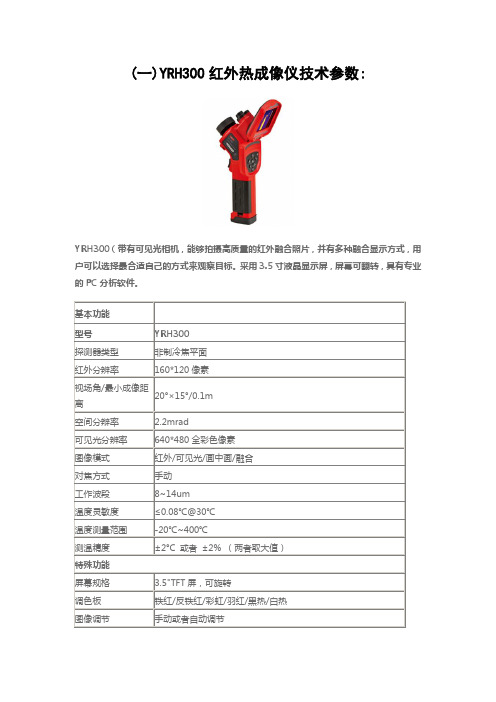
(一)YRH300红外热成像仪技术参数:
YRH300(带有可见光相机,能够拍摄高质量的红外融合照片,并有多种融合显示方式,用户可以选择最合适自己的方式来观察目标。
采用3.5寸液晶显示屏,屏幕可翻转,具有专业的PC分析软件。
YRH200红外热成像仪技术参数:
YRH200(160*120)像素红外热像仪即瞄即用,清晰成像:“直瞄式”设计,瞄准目标物体的同时,物体的图像数据及温度数据亦同时精彩显现,绝不遗漏任何瞬间。
本机拍摄红外图片时候的画面非常流畅,绝不出现掉帧或拖尾的现象。
可广泛应用于电力、建筑、电子、冶炼、能源、铁路、汽车、石化。
YRH300操作说明书
测温修正对话框
按压确认键激活主菜单,选中设置菜单中的测温修正项,按压确认键后弹出测温修正对话框(见图13)。用户可设置比辐系数、修正系数、修正温度、距离、湿度等项。按压上、下方向键切换各项目,左、右方向键设置项目内容。
YRH300矿用本质安全型
红外热像仪
操作说明书
本产品执行标准Q/ZDL003-2007
浙江大立科技股份有限公司
© 2008DALI TECHNOLOGY
为保证安全并获得最佳效能,在使用本热像仪之前,请详细阅读操作说明书,并妥善保存
警告
在任何情况下(开机或关机)不得将设备镜头直接对准强烈幅射源(如太阳、激光束直射或反射等),否则将对红外热像仪造成永久性损害。
测温模式对话框
如果选择“无”,按确认键后,将清除所有测温对象。
注:当删除单个测温对象时,可直接按“A”键选中测温对象,然后按“C”键删除。
4.3
通过调整温度与颜色的对应关系能够满足用户观察到色彩更加丰富、处理效果更加理想的图像,达到方便地对热故障进行查找分析的目的。
按压确认键,选择自动/手动并确认,可以切换自动调整和手动调整。也可以按压“A”键选中色标上下限时,手动调节图像。
[8]上限温度:色标的上限温度值。
[9]电池状态:显示当前的电池电量状态。电池的格数代表不同的电量。
[10]、[11]测温结果:显示测温对象的温度值。其中黄底黑字表示当前选中的测温对象的温度值。
[12]温度单位:当前采用的温度单位,可选择℃、℉或K。
注:由于各种型号红外热像仪功能不同,工作状态屏幕图形界面略有不同。
3.2
3.2.1
安装好电池后,按压红外热像仪电源开关3秒钟直至电源指示红灯亮起,等待开机界面完成后,红外热像仪进入工作状态。
红外热像仪使用说明书

红外热像仪使用说明书1. 引言该红外热像仪是一种专业的测温设备,能够以非接触的方式快速准确地测量目标物体的温度。
本使用说明书旨在帮助用户正确使用红外热像仪,以确保测温结果的准确性和安全性。
2. 产品概览2.1 外观描述红外热像仪采用人性化设计,具有手持便携性,操作简单方便。
外观包括显示屏、控制按钮、测温镜头等部分,整体呈现现代化风格。
2.2 技术参数- 测温范围:-20℃至 +500℃- 温度精度:±2℃或 ±2%- 分辨率:0.1℃- 温度单位:摄氏度(℃)或华氏度(℉)- 显示屏尺寸:3英寸(320x240像素)- 存储容量:最多可存储1000个图像- 电池类型:锂电池(内置可充电电池)- 连接接口:USB、蓝牙3. 使用步骤3.1 开机与关机长按电源按钮约3秒钟,直到屏幕显示图像时表示开机成功。
关机时,再次长按电源按钮约3秒钟,屏幕逐渐关闭即可。
3.2 测温准备在使用红外热像仪之前,请确保目标物体表面干净可见,没有覆盖物或污渍。
同时,根据实际需要选择合适的测温范围。
3.3 测温操作3.3.1 对焦调整通过控制按钮上的对焦调节功能,您可以调整红外热像仪的对焦距离,以获得清晰的测温图像。
3.3.2 拍摄图像将红外热像仪对准目标物体,按下拍照按钮,设备会自动捕捉并保存当前测温图像。
3.3.3 数据解析测温图像会显示在设备的屏幕上,您可以通过屏幕上的控制按钮进行图像放大、缩小、移动等操作。
3.3.4 温度测量在图像中选择您希望测量的区域,按下测温按钮,设备将显示该区域的温度数值。
4. 注意事项4.1 使用环境红外热像仪适用于室内外各种环境,但请避免使用在极端温度、潮湿或有腐蚀性气体的场所。
4.2 安全操作在使用红外热像仪时,应遵循相关安全操作规范,避免触摸高温物体,防止被辐射光损伤眼睛。
4.3 设备保养请定期清洁红外热像仪的镜头,避免灰尘或污渍对测温结果的影响。
同时,避免设备受到撞击或振动。
红外线热成像仪使用说明书
红外线热成像仪使用说明书第一章:产品概述1.1 产品介绍红外线热成像仪是一种基于红外热辐射原理进行测温和图像显示的专业工具。
该仪器通过捕捉并测量目标物体发出的红外热辐射,能够实时呈现目标物体的温度分布图像,并提供高精度的温度测量数据。
1.2 适用范围红外线热成像仪广泛应用于建筑、电力、冶金、制造业等领域。
它可用于故障诊断、设备维护、环境监测等多种场景,在各行各业中发挥重要作用。
第二章:产品特点2.1 高清晰度图像本产品配备高分辨率红外像传感器,能够实时显示清晰的热成像图像,突出目标物体的温度差异。
2.2 宽温度测量范围该热成像仪具有广泛的温度测量范围,可在-20℃至1200℃的温度范围内进行精确测量。
2.3 快速响应时间红外线热成像仪采用先进的图像处理技术,能够实时响应,迅速显示出目标物体的温度分布情况。
2.4 多种色带显示为了更好地观察目标物体的温度分布,我们为产品设计了多种色带显示模式,以满足不同工作环境和需求。
第三章:产品使用方法3.1 准备工作在使用红外线热成像仪之前,请确保设备已充电或连接电源适配器,同时检查红外线热成像仪是否处于正常工作状态。
3.2 操作步骤(1)长按开机按钮,待设备开机并自检完成后,即可进入工作状态。
(2)通过操控按钮或触摸屏幕,调整设备的参数设置,如色带模式、温度单位等。
(3)对目标物体进行扫描,观察屏幕上呈现的热成像图像。
(4)如需测量目标物体的温度,可将光标移动到目标物体上,设备会自动显示该位置的温度数据。
3.3 温度校准为了确保测量的准确性,本产品支持温度校准功能。
用户可根据实际需求设置相应的温度校准参数。
第四章:注意事项4.1 安全使用在使用红外线热成像仪时,请遵循以下安全原则:(1)请勿将仪器放置在高温环境或阳光直射下。
(2)使用过程中,请勿触摸红外线热成像仪镜头,避免损坏设备。
(3)使用完成后,请将红外线热成像仪存放在避光、干燥、通风的环境中。
4.2 保养与维护为了维护仪器的性能和正常使用寿命,请注意以下事项:(1)保持设备清洁干燥,避免进水或受潮。
红外热成像仪操作使用说明
TI20红外热成像仪操作使用说明目录1 TI20简介 (2)1.1 TI20组成及其附件 (2)1.1.1 TI2O的组成及其控件 (2)2 基本操作 (4)2.1 TI20的启动与关闭 (4)2.2 识别首页画面 (5)2.3 图像的聚焦与图像捕捉及其他 (7)2.3.1 图像的聚焦 (7)2.3.2 图像的捕捉 (7)2.4 其他操作 (7)2.4.1 水平的调整 (7)2.4.2 跨度的调整 (7)3.高级操作 (8)3.1 图像及其他的操作 (8)3.1.1图像的浏览与删除 (8)3.1.2 发射率的调整 (8)3.1.3 反射率的调整 (8)3.1.4 拍摄距离光点尺寸比的使用 (9)3.1.5报警极限设置 (10)4.INSIDE IR的操作说明 (10)4.1 基本操作 (10)4.1.1 TI20与PC的连接 (10)4.1.2 TI20日期和时间的设置 (11)4.1.3 图像数据的上传和下载 (12)4.1.4 热图像集合的导出 (12)4.1.5 热图像的导出 (12)5.红外热成像拍摄检测时的注意事项 (14)1 TI20简介Fluke Ti20 Imager(以下简称“Imager”)是当代技术最先进的轻型手持式热成像设备。
使用Imager,可即时、准确地获取远距离目标的热图像和辐射读数。
Imager 按人机工程学原理进行设计,左右手均可使用,只要扣动扳机,就可捕获热图像和数据。
Imager 最多可存储50 张图像,并可下载到您的个人电脑中,供存储、分析和制作报告之用。
InsideIR 辅助软件应用程序,可用来显示、检查、分析图像和数据,以确定与目标设备相关的定量及定性趋势。
您还可根据设备的条件、监控和资产管理的需要,使用InsideIR 来定义维护数据库。
Imager 能提供高性能的热成像功能,适于工业应用。
TI20热像仪的主要技术参数●电磁频谱范围:红外长波辐射7.5~14 μm●工作环境温度:0 °C~50 °C●测量温度范围:-10 °C~350 °C●报警温度范围:-15 °C~360 °C(可调)●存储容量: 50张热图像●具有防尘和防潮保护(IP54 级),可用于恶劣的工业环境。
红外热像仪操作说明书
红外热像仪操作说明书一、简介红外热像仪是一种用于检测、显示和记录目标表面温度分布的仪器设备。
本操作说明书旨在帮助用户了解该设备的基本功能和操作方法,以便正确、有效地使用。
二、设备外观及功能1. 外观红外热像仪外观紧凑,采用人体工程学设计,便于携带和操作。
设备主体由显示屏、镜头、控制按钮和电池仓组成。
2. 功能红外热像仪具备以下功能:- 温度测量:能够测量目标物体表面的温度,并以数字形式显示在屏幕上。
- 热像显示:将温度信息以热像形式显示在屏幕上,通过不同颜色的图像表达温度分布。
- 图像记录:支持将热像图像保存在内部存储器或可拓展的存储介质中,以供后续分析和比较。
- 视频记录:能够录制目标表面的温度变化过程,以便用户进行详细分析。
三、操作步骤1. 开机与关机- 开机:按下电源按钮并保持几秒钟直到设备启动。
- 关机:按下电源按钮并在菜单中选择“关机”选项。
2. 温度测量- 瞄准目标物体:通过查看屏幕,将设备对准需要测量温度的目标物体。
- 按下“测温”按钮:在设备上方的控制按钮中找到“测温”按钮,轻按一次进行测量。
- 查看温度结果:屏幕上将显示目标物体的表面温度。
3. 热像显示- 瞄准目标物体:与温度测量相同,将设备对准目标物体。
- 按下“热像”按钮:在控制按钮中找到“热像”按钮,轻按一次启动热像显示。
- 查看热像图像:屏幕将显示目标物体的热像图像,不同颜色代表不同温度区域。
4. 图像和视频记录- 图像记录:在热像显示模式下,按下“图像记录”按钮进行图像保存。
屏幕将提示保存成功。
- 视频记录:在热像显示模式下,按住“视频记录”按钮进行视频录制。
再次按下停止录制。
5. 其他功能本红外热像仪还具备一些其他功能,如温度单位切换、锁定测量、亮度调节等。
用户可根据实际需求,在菜单中选择相应选项进行设置和操作。
四、注意事项1. 确保设备电量:在使用前,请确保红外热像仪电池电量充足,以免影响操作效果。
2. 避免遮挡镜头:在使用过程中,请确保镜头没有被任何物体遮挡,以保证测量的准确性。
红外热像仪用户手册终结版解析

IPRE-160 红外热像仪用户手册! 警告、小心和注意定义!警告代表可能导致人身伤害或死亡的危险情况或行为。
!小心代表可能导致热像仪受损或数据永久丢失的情况或行为。
!注意代表对用户有用的提示信息。
重要信息–使用仪器前请阅读!警告–本仪器内置激光发射器,切勿凝视激光束。
激光规格为635 nm, 0.9mW, 二级。
!小心–因热像仪使用非常灵敏的热感应器,因此在任何情况下(开机或关机)不得将镜头直接对准强烈幅射源(如太阳、激光束直射或反射等),否则将对热像仪造成永久性损害!!小心 - 运输期间必须使用原配包装箱,使用和运输过程中请勿强烈摇晃或碰撞热像仪。
!小心–热像仪储存时建议使用原配包装箱,并放置在阴凉干燥,通风无强烈电磁场的环境中。
!小心-避免油渍及各种化学物质沾污镜头表面及损伤表面。
使用完毕后,请盖上镜头盖。
!小心 -为了防止数据丢失的潜在危险,请经常将数据复制(后备)于计算机中。
!注意 -在精确读取数据前,热像仪可能需要3-5分钟的预热过程。
!注意 -每一台热像仪出厂时都进行过温度校正,建议每年进行温度校正。
!小心 -请勿擅自打开机壳或进行改装,维修事宜仅可由本公司授权人员进行。
目录! 警告、小心和注意 (2)1简介 (5)1.1标准配置 (7)1.2可选配置 (7)2热像仪简介 (8)2.1功能键 (8)2.2接口 (11)3基本操作 (12)3.1电池安装及更换 (12)3.1.1电池装卸 (12)3.1.2更换电池 (13)3.2电池安全使用常识 (14)3.3快速入门 (15)3.3.1获取热像 (15)3.3.2温度测量 (15)3.3.3冻结和存储图像 (17)3.3.4回放图像 (17)3.3.5导出存储的图像 (17)4操作指南 (18)4.1操作界面描述 (18)4.1.1工作界面 (18)4.1.2主菜单 (19)4.1.3对话框 (20)4.1.4提示框 (20)4.2测温模式 (20)4.3自动/手动 (21)4.4设置 (22)4.4.1测温设置 (22)4.4.2测温修正 (23)4.4.3分析设置 (24)4.4.4时间设置 (25)4.4.5系统设置 (26)4.4.6系统信息 (27)4.4.7出厂设置 (27)4.5文件 (29)4.5.1打开 (29)4.5.2存储 (30)4.5.3存储设置 (32)4.5.4自动存储 (32)4.5.5删除 (33)4.5.6格式化 (33)5技术规格 (35)故障对策 (37)附录 A (38)常用材料的比辐射率(仅供参考) (38)附录B (39)出厂设置参数表 (39)1简介感谢您选择的系列手持式红外热像仪。
YRH600红外热像仪说明书及参数详情

YRH600矿用本质平安型红外热像仪说明书XX中煤工矿物资集团XX一、产品简介轻巧方便,设计符合人体工程学;防闪电路和特殊封装,在矿井下不会引起火花;最高温度/最低温度点自动捕捉,可自定义捕捉的X围;内置大容量闪存卡,可直接通过视频接口与电视连接,得到实时画面;优异的热成像质量和准确的温度测量;声光温度报警;内置激光指示器等。
二、工作原理红外热像仪是指能够检测电磁波光谱在红外波段的辐射,并能将不可见的红外辐射变成包含温度数据的可视图片的检测设备。
T.E.L 梁.152兆.1537敏7751三、本产品与红外测温仪的区别红外测温仪是指能够检测电磁波光谱在红外波段的辐射,并能将不可见的红外辐射变成直观的温度数据的检测设备。
红外测温仪与红外热像仪最大的区别在于:成像和测温的准确性。
注:电磁波谱:自然界中有各种各样的电磁辐射,每种电磁辐射都拥有不同的波长和振动频率,它们一起组成了电磁光谱。
人眼所能感觉到的可见光只是波谱中的一局部。
除此之外,还有我们现在比拟熟悉的红外线,紫外线等。
电磁波谱可任意划分成许多波长X围,这些波长X围我们称为“波段〞。
从电磁波谱上可以看到人眼所能感知的可将光的波段为380nm到780nm,而红外光的波段从780nm到1mm。
本产品的响应波长为8~14微米〔um〕。
四、规格参数型号YRH600探测器类型非制冷焦平面响应波长8~14um〔微米〕分辨率160×120性能温度分辨率0.1℃30℃五、部件介绍正面反面底部六、操作程序1〕翻开红外热像仪箱,从中取出红外热像仪。
2〕检查热像仪电池及SD卡是否安装到位,如无安装到位,按照要求安装电池及SD卡〔在井下及存在气体异常区域严禁随意拆卸电池,以免产生火花,造成事故;需拆卸时,必须检查周围环境中的瓦斯浓度,只有在气体浓度不超过规程的规定,方可进展。
〕3〕翻开热像仪的屏幕,使其与可见光镜头成90°夹角,以获得最正确的观察效果。
FLIR T600 热成像设备说明书

button and auto/manual focus.Auto orientation keeps On-screen data uprightImaging specificationsApplicationsEquipment described herein may require US Government authorization for export purposes. Diversion contrary to US law is prohibited. Imagery used for illustration purposes only. Specifications are subject to change without notice. ©2014 FLIR Systems, Inc. All rights reserved. 3592 (Rev. 02/14)Ordering Information55901-2102 ......................................FLIR T600 Thermal Imaging IR Camera (480x360) with Wi-Fi and standard 25° Lens 55901-2103 ......................................FLIR T600 Thermal Imaging IR Camera (480x360) with Wi-Fi plus 45° Lens Use thermal imaging to locate electrical/mechanical problems, hot spots and other heat issues before they turn into costly failures & production downtime or electrical fires.Scan substation components, motor control cabinets, buss ducts, and breaker panels for non-contact thermal imagesand temperature measurements to assess conditions.FLIR Commercial Systems Luxemburgstraat 22321 Meer BelgiumTel. : +32 (0) 3665 5100Fax : +32 (0) 3303 5624E-mail:*************FLIR Systems AB SwedenTel. : +46 (0)8 753 25 00FLIR Systems UKTel. : +44 (0)1732 220 011FLIR Systems GmbH GermanyTel. : +49 (0)69 95 00 900FLIR Systems FranceTel. : +33 (0)1 60 37 55 02 FLIR Systems ItalyTel. : +39 (0)2 99 45 10 01FLIR Commercial Systems SpainTel. : +34 91 573 48 27FLIR Systems, Middle East FZE Dubai - United Arab Emirates Tel. : +971 4 299 6898FLIR Systems RussiaTel. : + 7 495 669 70 72* After product registration on ACCESSORIEST197914 ........IR lens, f=41.3 mm (15°) with case T197922 .......IR lens, f=24.6 mm (25°) with case T197915 ........IR lens, f=13.1 mm (45°) with case T198059 ....... C lose-up IR lens, 2.9× (50 µm) with case T198060 ....... C lose-up IR lens, 5.8× (100 µm) withcaseT198166 ........ I R lens, f=88.9 mm (7°) with case andsupportT198065 .......IR lens, f=6.5 mm (80°) with caseT198066 ....... C lose-up IR lens, 1.5× (25 µm) with case T910814 .......Power supply, incl. multi plugs T198506 .......Li-Ion battery pack 3.7V 29Wh T911230ACC .Memory card SDHC 4 GB 1910423 B cable Std A <-> Mini-B T198509 ....... C igarette lighter adapter kit, 12 VDC,1.2 m/3.9 ft.T910930ACC .HDMI type C to DVI cable 1.5 mT910891ACC .HDMI type C to HDMI type A cable 1.5 m T198625 .......T198495 .......T198497 .......T198498 .......T198496 .......T198499 .......T197771ACC .Bluetooth headsetT198583 .......FLIR Tools+ (license only) T911093 .......Tool belt。
红外热像仪使用指南说明书

红外热像仪使用指南说明书红外热像仪是一种高科技设备,主要用于检测、测量以及观察物体的红外辐射能量,它在多个领域有着广泛的应用。
本指南将为用户提供红外热像仪的详细使用说明,包括使用前的准备、操作方法、常见问题解决等方面内容。
请用户在使用前仔细阅读本指南,并按照操作流程进行操作,以确保正确、安全地使用红外热像仪。
一、使用前的准备在使用红外热像仪之前,用户需要做一些准备工作。
首先,用户应仔细阅读设备的用户手册,了解设备的基本知识、技术指标以及安全注意事项。
其次,用户需要确保红外热像仪的电源充足,并检查设备的外观是否完好,是否有损坏或者松动的部件。
最后,用户需要准备一张合适的存储介质,以备存储红外图像和数据。
二、操作方法1. 开机与关机在准备工作完成后,用户可以按下红外热像仪的电源开关,待设备自检完成后,即可进入工作状态。
在使用完毕后,用户应按照以下步骤关机:a. 停止数据采集,并保存当前图像和数据;b. 将红外热像仪的电源开关切换至关机状态;c. 若红外热像仪使用电池供电,则需要在不使用时,将电池从设备中取出。
2. 图像设置与观察a. 通过红外热像仪的菜单导航键,用户可以调整图像的亮度、对比度等参数,以获得更清晰、准确的图像。
同时,用户也可以设置内置测温点、区域,以进行更准确的测温。
b. 当红外热像仪处于工作状态时,用户可以通过眼镜视口观察目标物体,并将目标物体的红外图像实时显示在红外热像仪的屏幕上。
用户可以通过手动或自动调节红外热像仪的焦距、放大倍数等功能,获得更清晰的图像。
3. 数据保存与导出红外热像仪通常有内部存储器和外部存储卡两种数据存储方式。
用户可以根据需要选择合适的存储介质,并按照以下步骤进行数据的保存与导出:a. 在红外热像仪菜单中选择“保存图像和数据”选项;b. 根据提示选择存储位置和文件名,确认保存;c. 如需将数据导出至电脑或其他设备,用户可以将存储介质插入对应的读卡器,通过数据线或蓝牙等方式将数据传输至目标设备。
YRH300矿用本安型红外热像仪热成像仪说明书
国家安全标志证号: MAK130144注:此型号为高配,可拍照,可摄录。
一、产品概述YRH300红外热成像仪,以先进的UFPA非制冷焦平面红外控测器和高质量的光学镜头为核心,结合方便快捷的操作系统、依靠水平的人体工学结构设计、功能完善的拓展配件,为适用用户打造了一款“成像清晰、测量准确、操作简单、携带轻便”的理想测温工具,是现场温度检测、预防性维护等应用场所不二选择。
测量原理:红外辐射:在自然界中,任何温度高于绝对零度(-273℃)的物体都会向外界辐射红外线,物体的辐射能量的大小,和物体表面的温度高低相关。
红外控测器:能把被测物体红外辐射量的变化变成电量变化的装置,也即将光信号转换成电信号。
红外热成像仪利用光学器件将被测目标辐射的红外能量聚集在红外探测器上,将探测器上每个像素点接收的红外数据进行处理后,对比预先标定好的温度数据,转像成标准的视频格式并显示出来,从而实现了将被测物的热分布转像为红外热图的过程。
为种红外热图与被测物体表面的热分布相对应,热图像上面的不同颜色代表被测物体的不同温度。
二、工作环境:a)工作温度:(0~40)℃;b)平均相对湿度:≤ 98% ;c)大气压力:(80~116)kPa;d)工作环境:有瓦斯或煤尘爆炸危险,但无显著振动和冲击,无破坏绝缘的腐蚀气体场所。
三、技术指标1、技术参数四、适用范围●探测煤矿井下隐蔽性火区分布、火源位置●顶板冒落与老塘透水分析●检查运输机、皮带及托辊的发热状况●测量采煤机组、水泵、局扇、防爆电机及动力设备(包括动力电览)的温升●井下中央与采区变电所各种电气设备接头、开关等事故隐患监测●矿难救援;并可利用长期贮存的热图帮助分析井下事故●科学研究●预警地面矸子山与煤堆自然发火,变电所各种接头、排线、开关及变压器的故障检测技术QQ:541595498。
YRH300应用介绍
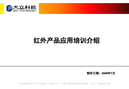
3、由于炸药自燃过程反应慢,人眼很难判断,使用红外线热 像仪可在第一时间内检测判断有异常情况的炸药,彻底消除 由于过期或劣质炸药自燃,热量积聚,导致发生爆炸的安全 隐患。
Page 14
应用-人体测温(疾病预防)
1至爱包子no1红外产品应用培训介绍制作日期2009年制作日期2009年7月本资料仅供大立公司使用未经许可不得在指定机构以外传阅引用复制或分发dl700系列产品应用介绍t6系列产品应用介绍txi系列产品应用介绍yrh系列产品应用介绍系列产品应用介绍page2应用井下探火应用井下探火煤层表面异常热点超过50度内部有隐火煤层表面异常热点超过50度内部有隐火注浆防灭火后效果明显温度明显下降注浆防灭火后效果明显温度明显下降page3应用井下试水应用井下试水火区出水在32度以上度以上煤炭安全规程第二百四十八条煤炭安全规程第二百四十八条火区出水温度高于25度即表明火未熄灭火区出水温度高于25度即表明火未熄灭25page4应用应用井下探水含水顶板温度在23度左右明显高于正常顶板同煤1号矿号矿含水顶板温度在23度左右明显高于正常顶板同煤1号矿度左右明显高于正常顶板正常顶板在17度左右同煤号矿号矿正常顶板在度左右同煤1号矿度左右page5应用井下观测密闭应用井下观测密闭火区密闭要检查墙温气温火区密闭要检查墙温气温水温及各种气体浓度的变化重点掌握一氧化碳浓度的变化
Page 3
应用--井下试水
火区出水在 32度以上
煤炭安全规程第二百四十八条:
火区出水温度高于25度即表明火未熄灭
Page 4
应用-井下探水
含水顶板温度在23度左右明显高于正常顶板(同煤1号矿)
FLIR T600 热成像摄像头产品介绍说明书

imágenes térmicas nítidas con 172captura de imagen y capacidad de enfoque automático/manual. La orientación automática mantiene los datos de la pantalla en verticalEspecificaciones de la imagenAplicacionesEl equipo descrito en este documento puede requerir la autorización del Gobierno de EE. UU. para su exportación. Quedan prohibidas las desviaciones contrarias a la ley deEE.UU. Las imágenes utilizadas tienen un fin meramente ilustrativo. Las especificaciones están sujetas a cambios sin previo aviso. ©2014 FLIR Systems, Inc. Todos los derechos reservados. 3592 (Ver. 02/14)Información para los pedidos55903-2822 ........Cámara termográfica de infrarrojos (480 x 360) FLIR T600 con Wi-Fi y lente estándar de 25°55903-2922 ........Cámara termográfica de infrarrojos (480 x 360) FLIR T600 con Wi-Fi y lente de 45°Utilice la termografía para localizar problemas eléctricos/mecánicos, puntos calientes y otros contratiempos antes de que se conviertan en averías y períodos de inactividad en la producción costosos o en fallos eléctricos.Escanee los componentes de una subestación, cuadros de control de motores, conductos de barras y cuadros de distribución, y consiga imágenes térmicas y medidas de temperatura sin contacto para evaluar las condiciones enlas que se encuentran.FLIR Commercial Systems Luxemburgstraat 22321 Meer BélgicaTlf.: +32 0 3665 5100Fax: +32 (0) 3303 5624Correoelectrónico:*************FLIR Systems AB SueciaTlf.: +46 (0)8 753 25 00FLIR Systems UKTlf.: +44 (0)1732 220 011FLIR Systems GmbH AlemaniaTlf.: +49 (0)69 95 00 900FLIR Systems FranceTlf.: +33 (0)1 60 37 55 02 FLIR Systems ItalyTlf.: +39 (0)2 99 45 10 01FLIR Commercial Systems EspañaTlf.: + +34 91 573 48 27FLIR Systems, Middle East FZE Dubái - Emiratos Árabes Unidos Tlf.: +971 4 299 6898FLIR Systems Russia Tlf.: + 7 495 669 70 72* Al registrar su producto FLIR en: ACCESÓRIOS T197914 ...... L ente IR, f=41,3 mm (15°) conestucheT197922 ...... L ente IR, f=24,6 mm (25°) conestucheT197915 ...... L ente IR, f=13,1 mm (45°) conestucheT198059 ...... L ente IR de aproximación, 2,9× (50µm) con estucheT198060 ...... L ente IR de aproximación, 5,8× (100µm) con estucheT198166 ...... L ente IR, f=88,9 mm (7°) con estuchey soporte T198065 ......Lente IR, f=6,5 mm (80°) con estuche T198066 ...... L ente IR de aproximación, 1,5× (25µm) con estucheT910814 ...... F uente de alimentación con variosconectores incluidosT198506 ......Pila de ión de litio de 3,7 V 29 Wh T911230ACC Tarjeta de memoria SDHC de 4 GB 1910423 ......Cable USB Std A <-> Mini-B T198509 ...... K it adaptador para encendedor delcoche, 12 V CC, 1,2 m/3,9 pies.T910930ACC Cable HDMI tipo C a DVI de 1,5 m T910891ACC C able HDMI tipo C a HDMI tipo A de1,5 mT198625 ......Maletín de transporte rígido T198495 ......EstucheT198497 ......Tapa grande para objetivo T198498 ......Adaptador de trípode T198496 ......LápizT198499 ......Correa para colgar del cuello T197771ACC Auriculares Bluetooth T198583 ......FLIR Tools+ (solo licencia) T911093 ......Cinturón de herramientas。
- 1、下载文档前请自行甄别文档内容的完整性,平台不提供额外的编辑、内容补充、找答案等附加服务。
- 2、"仅部分预览"的文档,不可在线预览部分如存在完整性等问题,可反馈申请退款(可完整预览的文档不适用该条件!)。
- 3、如文档侵犯您的权益,请联系客服反馈,我们会尽快为您处理(人工客服工作时间:9:00-18:30)。
YRH600矿用本质安全型红外热像仪
说
明
书
山东中煤工矿物资集团有限公司
一、产品简介
轻巧方便,设计符合人体工程学;防闪电路和特殊封装,在矿井下不会引起火花;最高温度/最低温度点自动捕捉,可自定义捕捉的范围;内置大容量闪存卡,可直接通过视频接口与电视连接,得到实时画面;优异的热成像质量和精确的温度测量;声光温度报警;内置激光指示器等。
二、工作原理
红外热像仪是指能够检测电磁波光谱在红外波段的辐射,并能将不可见的红外辐射变成包含温度数据的可视图片的检测设备。
T.E.L 梁.152兆.1537敏7751
三、本产品与红外测温仪的区别
红外测温仪是指能够检测电磁波光谱在红外波段的辐射,并能将不可见的红外辐射变成直观的温度数据的检测设备。
红外测温仪与红外热像仪最大的区别在于:成像和测温的精确性。
注:电磁波谱:自然界中有各种各样的电磁辐射,每种电磁辐射都拥有不同的波长和振动频率,它们一起组成了电磁光谱。
人眼所能感觉到的可见光只是波谱中的一部分。
除此之外,还有我们现在比较熟悉的红外线,紫外线等。
电磁波谱可任意划分成许多波长范围,这些波长范围我们称为“波段”。
从电磁波谱上可以看到人眼所能感知的可将光的波段为380nm到780nm,而红外光的波段从780nm到1mm。
本产品的响应波长为8~14微米(um)。
四、规格参数
型号YRH600
探测器类型非制冷焦平面响应波长8~14um(微米)分辨率160×120
性能温度分辨率0.1℃@30℃
视场角20°×15°最小焦距0.1m
可见光镜头分辨率160×120,全彩照明灯有
图像格式
视频输出PLA/NTSC
图像显示伪彩色,多种存储可移动Mini SD卡,最高支持2GB
测温测温范围-20~250℃
-20~600℃(可选)
-20~1000℃(可选)
-20~1500℃(可选)精确度±2℃或±2%
分析功能点分析共4个,包括3个可移动点及1个自动捕捉最高/最低温度
点
自动捕捉自动全屏捕捉最高或最低温度点
温度警报可设置高于或低于一定温度即警报
等温分析有
图像调整自动或手动调整图像的对比度及亮度
校正辐射率/目的距离/环境温度/湿度
PC软件支
持
分析软件报告生成软件激光点类型TypeⅡ
功耗1mw
波长635nm(红色)
系统设置项目日期/温度单位/语言
待机自动待机
电池及外置供电可充电锂电池,及12V直流外置供电电池续航约2.5小时
工作环境操作温度-15℃~50℃保存温度-40℃~70℃相对湿度10~95%
接口界面USB2.0接口(可选),蓝牙耳机(可选),视频输出物理特性重量≈650g(包括电池)
封装标准IP54
抗冲击工作时:25G
抗震动工作时:2G
五、部件介绍
正面
背面底部
六、操作程序
1)打开红外热像仪箱,从中取出红外热像仪。
2)检查热像仪电池及SD卡是否安装到位,如无安装到位,按照要求安装电池及SD卡(在井下及存在气体异常区域严禁随意拆卸电池,以免产生火花,造成事故;需拆卸时,必须检查周围环境中的瓦斯浓度,只有在气体浓度不超过规程的规定,方可进行。
)3)翻开热像仪的屏幕,使其与可见光镜头成90°夹角,以获得最佳的观察效果。
4)按电源开关键约3秒钟,会听到“嗡---”的警报声,说明正在开机。
5)取下镜头盖,用手动调焦或自动调焦(长按A键)将焦距调至满意位置。
6)按确定/菜单键一次,然后按上下键选择“视频选择”---确定/菜单键---按右键,可在可见光图像/红外图像/红外图像﹢可见光图像之间切换,选择所需要的图像。
7)如需对所物体进行瞄准,请按下自定义按键(设置为激光键),对物体进行瞄准,自定义按键还可设置为调焦键或照明灯键(按确定/菜单键---设置---其他---开关设置---确定/菜单键进行选择)。
8)选择好所需要的图像后,按确定/菜单键进行存储。
9)如需对所拍摄的图像进行保存,按确定/菜单键---选择文件---按确定/菜单键---选择保存---按确定/菜单键,图片将储存在SD 卡上,将能够进行后期图片分析与处理。
10)进入菜单后,如不想进行相关参数的更改,可按C键,取消设置。
11)其他相关参数的设置请参照第6、7条进行,在此不一一赘述。
12)按S键将会使当前正在拍摄的画面冻结,以便进行现场分析,再次按S键将会使画面进入拍摄状态。
13)长按电源开关键,当屏幕出现:shut down,松开电源开关键,热成像仪关机。
14)关机后盖上镜头盖,将屏幕转到与手柄平行位置(长期不用,
可将电池取出),放入仪器箱内放好。
七、其他注意事项
Null---空模式,当前没有选择菜单或分析工具。
E---当前设置的辐射率
IH---等温显示的温度上限
IL---等温显示的温度下限
八、热像仪的维护和保养
1)热像仪每次使用完后,请使用清洁的软布或者其他专用布清洁擦拭体。
2)请勿使用手或其他不洁的布料擦拭镜头,以免造成镜头划伤。
应使用专用吸耳球吹拭镜头上附着的灰尘,然后再使用专用的镜头布或清洁的软布轻轻擦拭镜头表面。
3)请勿将激光指向人或者动物的眼睛,直视激光有可能对视力造成永久的伤害。
4)热像仪所使用的电池为智慧型锂聚合物可充电电池。
每次充电之前都不需要对电池进行放电。
可以在任何电量状态下为电池充电,但由于充电次数最多约300次(电池寿命),为了延长电池的使用寿命,建议电池电量自然耗尽后再对电池进行充电,以延长电池寿命。
充电过程中,充电器上的指示灯为常亮红色,充电完毕后变为绿色。
