TEM 原理及制样
透射电镜制样流程
透射电镜制样流程透射电镜(Transmission Electron Microscopy,TEM)制样是指通过一系列的化学和物理方法来制取透射电镜所需的样品。
透射电镜是一种高分辨率的显微镜,可以在纳米尺度下观察材料的原子结构和微观形态。
为了获取高质量的TEM图像,制样过程非常关键。
下面将详细介绍透射电镜制样的流程。
1.样品制备:样品可以是纳米颗粒、薄膜、纤维或生物样品等。
首先,准备适宜的基底材料,如碳膜覆盖的铜网格或碳膜覆盖的铜刀片。
样品通常需要制成非常薄的切片,通常在50到100纳米的厚度范围内。
制备方法包括机械切割、电解石蠟切片、离子切割或电离蚀刻等。
2.固定和固化:对于生物样品,需要先进行固定处理,以保持样品的形态和结构。
常用的固定剂包括戊二醛、酸性醛或重金属盐。
然后,固定的样品需要进一步处理以固化,如用过氧化物、树脂或聚合物进行浸渍,以增加样品的稳定性。
3.切割和悬浮:将固化的样品切割成适当的尺寸和形状。
使用超微切割机、离子切割仪或其他切割工具进行切割。
切割后,样品通常会悬浮在水或有机溶液中,以便进一步处理。
4.脱水和对比染色:脱水是将样品从水中逐渐转移到有机溶剂中的过程。
这种处理可以控制样品的体积,以减少对比染色和观察中的伪影。
脱水通常通过渗透固定液逐渐转移,然后通过有机溶剂(如醋酸乙酯、丙酮或丙二醇)进行交换。
5.嵌入:将样品嵌入到透明的聚合物或树脂中。
嵌入过程中,通常采用逐渐增加浓度的树脂混合物,以确保样品得到完全浸透。
然后,将样品与树脂进行硬化,通常在高温下进行。
6.超薄切片:将固化的样品切割成非常薄的切片。
使用超薄切片机和钻磨刀片进行切割。
切割后的切片应尽快收集并转移到透明的铜网格或铜刀片上。
7.超薄切片处理:超薄切片通常需要进行后继处理以增强对比度和解决其他问题。
这可能包括染色、胶层增强或薄膜剥离等方法。
8.观察:将制备好的样品放入透射电镜中进行观察。
在观察前,样品需要在真空中或过氮气中去除气泡和其他杂质。
第三章TEM样品制备技术ppt课件

高分辨原子像要求的样品厚度应在10nm以下,甚至5nm以下。
经营者提供商品或者服务有欺诈行为 的,应 当按照 消费者 的要求 增加赔 偿其受 到的损 失,增 加赔偿 的金额 为消费 者购买 商品的 价款或 接受服 务的费 用
经营者提供商品或者服务有欺诈行为 的,应 当按照 消费者 的要求 增加赔 偿其受 到的损 失,增 加赔偿 的金额 为消费 者购买 商品的 价款或 接受服 务的费 用
一、质厚衬度
衬度:眼睛能观察到的或者其它媒介能记录到 的光强度或感光度的差异; 质厚衬度就是样品中不同部位由于原子序数不 同或者密度不同、样品厚度不同,入射电子被散 射后能通过物镜光阑参与成像的电子数量不同, 从而在图像上体现出的强度的差别。
经营者提供商品或者服务有欺诈行为 的,应 当按照 消费者 的要求 增加赔 偿其受 到的损 失,增 加赔偿 的金额 为消费 者购买 商品的 价款或 接受服 务的费 用
常用电解减薄液
序号
电解液成分与配比
适用材料
1
乙醇(80ml),冰醋酸(80ml), 高氯酸(15ml),甘油(10ml)
高温合金,耐
热钢,铝及其 合金。
的结构和工作原理,而且应该掌握样品制备的基本技术。
电镜样品制备的特点
电镜样品制备属于破坏性分析。 花费时间很多,有时甚至超过整个研究工作量的一半以上。 制样技术随电镜技术的发展而发展的。 制样技术分两大类:生物样品制备、材料科学样品制备。本文只
讲述材料科学中的制样技术,这些试样大多是有一定硬度的固态 物质。 制备成薄膜,膜厚取决于电子束的穿透能力和分析要求。
支持膜分散粉末法是 常用的制样方法。
tem截面样品的制备
tem截面样品的制备
TEM(透射电子显微镜)截面样品的制备通常包括以下步骤:
1. 样品选择:选择需要观察的材料,并根据研究目的确定采样位置。
2. 机械切割:使用机械切割工具(如钢丝锯、金刚石刀片等)将样品切割成较小的块状或薄片。
3. 粗磨和打磨:使用研磨机、砂纸或研磨液对样品进行粗磨和打磨,以去除切割过程中引入的痕迹和不平整表面。
4. 薄化:使用离心切割机、电解腐蚀或离子蚀刻等方法使样品变得足够薄。
这一步旨在减小样品的厚度,以便光线能够透过并进入透射电子显微镜。
5. 悬浮和转移:将薄片从切割基底上悬浮并转移到供应载玻片或网格碳膜上。
可以使用特殊夹持装置或粘贴剂来帮助悬浮和转移过程。
6. 电子束刻蚀:使用电子束蚀刻机对样品进行细微的刻蚀
处理,以去除可能存在的氧化物或其他杂质,并提高样品表面的平整度。
7. 清洗和干燥:用溶剂或超声波清洗样品,以去除表面的污染物。
然后将样品在低压条件下干燥,避免水分残留。
8. 检验和观察:使用透射电子显微镜观察和记录样品的截面形貌和微结构信息。
需要注意的是,TEM截面样品制备过程中的每个步骤都需要谨慎操作,以确保样品的质量和可观察性。
具体的制备方法和工艺参数可能会因不同的样品类型和研究需求而有所差异。
透射电镜(TEM)讲义

05
TEM操作与注意事项
操作步骤与技巧
01
02
03
04
准备样品
选择适当的样品,进行适当的 处理和固定,以确保观察效果 最佳。
调整仪器参数
根据观察需求,调整透射电镜 的加速电压、放大倍数等参数 ,以达到最佳观察效果。
操作步骤
按照仪器操作手册的步骤进行 操作,包括安装样品、调整焦 距、观察记录等。
技巧
定量分析方法
颗粒统计
对图像中颗粒的数量、大 小和分布进行统计,计算 颗粒的平均尺寸和粒度分 布。
电子衍射分析
利用电子衍射技术分析晶 体结构和相组成,确定晶 格常数和晶面间距。
能谱分析
通过能谱仪测定图像中各 点的元素组成和相对含量, 进行定性和定量分析。
04
TEM图像解析实例
晶体结构分析
利用高分辨的TEM图像,可以观察到晶体内部的原 子排列和晶体结构,如面心立方、体心立方或六方 密排结构等。
掌握操作技巧,如正确使用操 作杆、合理利用观察窗口等, 以提高观察效果和效率。
仪器维护与保养
定期清洁
定期对透射电镜进行清 洁,保持仪器内部和外
部的清洁度。
检查部件
更换消耗品
定期检查透射电镜的部 件,如电子枪、镜筒等,
确保其正常工作。
根据需要,及时更换透射 电镜的消耗品,如真空泵
油、电子枪灯丝等。
保养计划
在操作透射电镜时,应严格遵守操作规程, 确保仪器和人身安全。
THANK YOU
感谢聆听
80%
观察模式
根据观察目的选择不同的观察模 式,如明场、暗场、相位对比和 微分干涉等。
图像解析与解读
01
02
03
透射电镜细胞样品制备流程
透射电镜细胞样品制备流程以透射电镜细胞样品制备流程为标题,我们来介绍一下这个过程。
透射电镜(Transmission Electron Microscope,TEM)是一种高分辨率的显微镜,可以用来观察非常微小的细胞结构和内部细节。
为了获得高质量的透射电镜图像,样品的制备非常重要。
下面我们将详细介绍透射电镜细胞样品制备的流程。
第一步,收集细胞样品。
可以选择不同类型的细胞样品,如动物细胞、植物细胞或微生物细胞。
细胞样品可以从生物实验室中获得,也可以通过培养细胞来获取。
第二步,固定细胞样品。
固定是为了保持细胞在制备和观察过程中的形态和结构。
常用的固定剂有乙醛、戊二醛等。
将细胞样品与固定剂混合,使细胞膜和细胞器固定在原位,停止细胞内部的生化反应。
第三步,脱水样品。
将固定的细胞样品通过一系列浓度递增的乙醇溶液进行脱水处理。
脱水的目的是去除细胞内外的水分,使样品适合后续的浸渍和包埋。
第四步,浸渍和包埋样品。
将脱水后的细胞样品置于透明的有机溶剂中,如丙酮或环氧树脂。
浸渍的目的是使样品与嵌入剂之间充分接触,逐渐将有机溶剂替换为嵌入剂。
然后将样品转移到嵌入剂中,使细胞样品被完全包裹在固体嵌入剂中。
第五步,切片样品。
使用超薄切片机将包埋的细胞样品切成非常薄的切片,一般为50-100纳米。
切片的过程需要非常小心和精确,以确保切片的质量和一致性。
第六步,上膜样品。
将切好的细胞样品转移到透明的膜上,如碳膜或铜膜。
上膜的目的是增强样品的稳定性和导电性,以便在透射电镜中观察。
第七步,染色样品。
可以使用染色剂来增加样品的对比度和可见度。
常用的染色剂有重金属盐(如铋盐)和阴离子染料(如尼格罗红)。
染色的过程需要小心操作,以避免染料的过度使用或样品的损坏。
第八步,干燥样品。
将上膜和染色后的样品放置在通风设备中,使其自然干燥。
干燥后的样品可以储存在干燥剂中,以保持其稳定性和保存时间。
将制备好的样品放入透射电镜中进行观察。
通过透射电镜,我们可以获得高分辨率和高对比度的细胞图像,从而更好地研究细胞的结构和功能。
tem工作原理

tem工作原理
TEM(透射电子显微镜)工作原理是利用电子束穿透物质样
本并通过透射方式形成样本的显微图像。
TEM是一种高分辨
率的显微镜,可用于观察和研究非常细小的物质结构。
TEM的基本构造包括电子源、透镜系统和探测器。
首先,电
子源产生高能电子束。
然后,电子束通过一系列透镜系统,包括电子透镜和物镜透镜,来聚焦电子束并使其通过样本。
透过样本后,电子束进入投射透镜,再通过聚焦透镜,最后进入探测器。
在通过样本的过程中,一部分电子束会被样本中的原子核、电子等相互作用而散射出去,另一部分电子束则会透过样本并与探测器相互作用。
探测器收集到的透射电子信号会转化为电信号,并通过电子学系统进行放大和处理。
最终,这些电信号被转化为图像,并通过显示器或拍摄设备进行观察和记录。
TEM的工作原理基于电子的波粒二象性,在透明薄样品的情
况下,电子束的穿透性可以用来解析样本内部的微观结构。
TEM在分辨率方面具有很高的优势,可以观察到纳米级别的
细小结构和特征。
同时,TEM还可以通过调整电子束的能量,实现不同样本性质的观测,如原子分辨率、晶体结构、元素分析等。
总而言之,TEM的工作原理是通过电子束穿透样本,利用透
射方式形成样本的显微图像。
这种技术在材料科学、生物科学和纳米科技等领域具有重要的应用价值。
TEM制样方法范文
TEM制样方法范文TEM(Transmission Electron Microscopy)是一种高分辨率电子显微镜技术,可用于观察和分析材料的微观结构。
TEM利用电子束传输样品并收集透射电子图像,通过显微镜的透射系统产生高分辨率图像。
在TEM制样过程中,样品的制备是非常关键的步骤,因为正确的制备样品对于获得高质量、准确的TEM图像至关重要。
以下是几种常见的TEM制样方法:1.切片法切片法是TEM制样的最常见方法之一、首先,样品通常是固态或半固态的,被嵌入到一种硬化树脂中,使其变得坚固。
然后,使用超微薄切片器将样品切成非常薄的切片,通常在50-100 nm的范围内。
这些切片随后会被转移到一小块碳膜上,并收集在TEM网格上。
最后,将TEM网格放置在TEM样品室中进行显微观察。
2.离子薄化法离子薄化法是一种常用的制备TEM样品的方法,尤其适用于研究金属、合金和陶瓷等材料。
首先,将样品切片制备成片上约厚10-100μm的样品。
然后,将样品放入一个离子薄化装置中,在真空环境中通过离子束装置加速产生高能离子束。
这些高能离子会剥离样品表面的原子,逐渐将其薄化。
通过定期检查样品的厚度,可以控制薄化的过程,直到达到所需的厚度。
最后,将薄样品转移到TEM网格上进行观察。
3.冻结切片法冻结切片法适用于需要观察生物样品或水溶液中的材料的TEM制样。
在这个方法中,样品首先被冷冻,通常是通过液氮或液氮气体冷冻。
然后,使用特殊的微波冻结设备将样品顺利地冻结。
接着,从冷冻样品中制备出非常薄的切片,这样可以保留样品的原始结构和化学性质。
最后,将这些冻结切片转移到TEM网格上进行显微观察。
4.真空沉积法真空沉积法是一种用于制备包含不透明溶液或薄膜样品的TEM样品的方法。
首先,将样品溶液或薄膜放置在TEM网格上。
然后,在真空室中将样品置于高温下,使之脱水并形成固体表面。
最后,在低温下,以较高速度蒸发样品周围的水分子,制备出干燥的样品。
透射电镜样品制备方法
透射电镜样品制备方法透射电镜(Transmission Electron Microscopy,简称TEM)是一种高分辨率的显微镜,能够观察到原子尺度的物质结构。
在进行透射电镜观察前,样品的制备是至关重要的一步。
本文将介绍透射电镜样品制备的方法,希望能够帮助大家更好地进行样品制备工作。
首先,样品的制备要求样品具有一定的薄度。
因此,在进行透射电镜观察前,通常需要将样品切割成极薄的切片。
对于生物样品,可以采用超薄切片机进行切割;对于金属、陶瓷等样品,可以采用离子蚀刻或机械打磨的方法制备薄片。
在进行切割或打磨时,需要保持样品表面的平整和光洁,以确保透射电镜观察时获得清晰的图像。
其次,样品的制备还需要考虑到样品的固定和染色。
对于生物样品,固定和染色是非常重要的步骤。
固定可以保持样品的形态和结构不变,而染色则可以使样品在透射电镜下更易于观察。
常用的固定剂包括乙醛、戊二醛等,而染色剂则根据需要选择不同的染色方法。
另外,样品的制备还需要考虑到样品的支撑。
在进行透射电镜观察时,样品通常需要支撑在一种载体上,以便于放置在透射电镜的样品台上。
常用的载体包括碳膜、网格和硅片等。
在选择载体时,需要考虑到载体的透明性、机械强度和热稳定性等因素。
最后,样品的制备还需要考虑到真空条件。
透射电镜通常在高真空环境下进行观察,因此样品制备时需要保证样品的干燥和密封。
特别是对于生物样品,需要进行脱水和干燥处理,以避免在真空环境下产生气泡或水蒸汽,影响透射电镜观察效果。
总之,透射电镜样品制备是透射电镜观察工作中至关重要的一步。
在进行样品制备时,需要考虑到样品的薄度、固定和染色、支撑和真空条件等因素,以确保最终获得清晰、准确的透射电镜图像。
希望本文介绍的方法能够对大家进行透射电镜样品制备工作有所帮助。
tem透射电镜的样品制备方法

tem透射电镜的样品制备方法TEM(透射电子显微镜)是一种常用的高分辨率显微镜,可以观察到物质的结构和组成。
样品制备对于TEM观测至关重要,良好的样品制备可以提供高质量的显微图像。
以下是TEM透射电镜的样品制备方法的详细讨论。
1.样品选择:选择适合TEM观察的样品,典型的样品包括纳米材料、生物细胞、材料薄膜等。
根据需要选择合适的样品尺寸和形状。
2.样品固定:根据样品的特性和需要,采取合适的方法将样品固定在支撑物上。
常用的方法包括离心沉淀、滴定、蒸发浓缩等。
对于生物样品,可以使用化学固定剂(如戊二醛)进行化学固定。
3.样品切片:对于大尺寸或不透明的样品,需要将其切割成薄片,一般要求切片尺寸在100 nm以下。
常用的切片工具有超声切割仪、离子切割仪等。
切割样品时要注意样品的定位和定向,以确保观察到感兴趣的区域。
4.样品脱水:对于生物样品,需要将其进行脱水处理。
脱水可以使用乙醇和丙酮等有机溶剂,逐渐将样品中的水分替换为有机溶剂。
脱水过程中要避免剧烈振荡,以防止样品的破坏。
5.样品浸渍:将脱水后的样品浸渍在透明介质中,如环氧树脂或聚合物。
浸渍过程中需要避免气泡和异物的进入,以保持样品的质量。
6.样品调平:将浸渍后的样品放在平板上,用研磨纸将其调平。
调平过程中要注意避免样品的损坏。
7.样品切割:将调平后的样品切成适当尺寸的小块,便于后续的操作。
切割时要使用锋利的刀具,以保证切面的平整度。
8.样品研磨:使用研磨纸或研磨腰带对样品进行研磨,以使其表面更加平整。
研磨过程中要注意研磨力度的控制,以免样品的破损。
9.样品薄化:使用电子束或离子束对样品进行薄化处理,将其厚度控制在适当的范围内。
薄化过程中要注意能量和时间的控制,以避免样品的损坏。
10.样品清洁:最后,使用有机溶剂或气流将样品上的杂质去除,使样品表面干净。
以上就是TEM透射电镜的样品制备方法的详细讨论。
不同的样品可能需要不同的制备方法,需要根据实际情况进行调整。
TEM生物样品特殊制备技术课件
硫胺焦磷酸酯酶(TPP)技术获得的选择性染色。大鼠附睾细胞 内的高尔基器只有内层着色。(×33000)
肝细胞中毛细胆管呈现ALP反应阳性(箭头)×15000
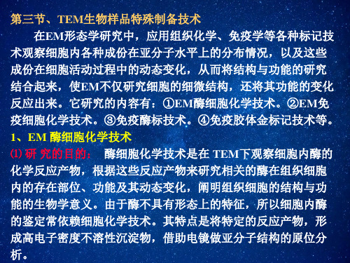
第四节、免疫电镜技术 Immuno electronmicroscopic technique
1、概念:
免疫电镜技术是免疫学和电镜技术的结合,其特点是将免疫 学中抗原抗体反应的特异性与组织化学中形态学的可见性,结合 电镜的高分辨能力和放大本领,用胶体金标记抗原,在亚细胞水 平上研究组织和细胞的形态与功能,还可进行细胞内抗原的定性 定位研究,从而将细胞结构与功能代谢紧密结合起来。
醛类物质对不同细胞器的固定和对酶的活性作用
细胞器 胞基质 内质网 线粒体 核周隙 GOL体 酶活性 戊二醛 +++ +++ +++ +++ +++ 一般
甲 醛 ++ +++ +++ ++ ++ 优秀
在选择固定剂时,首先考虑保存酶的活性,后考虑结构的 保存。由表可见,戊二醛的固定作用优于甲醛,而甲醛保存酶 的活性作用大于戊二醛。因此电镜细胞化学技术中常用戊二醛 和甲醛的混合液进行样品固定。
从理论上讲,若想保存好样品,需充分固定。但固定越彻底, 酶的失活越严重。要想保存酶的活性,最好是先孵育后固定,但 先孵育导致细胞微细结构的损伤,反应不均,酶反应物扩散、流 失,出现与酶无关部位定居的假象。这些矛盾是EM细胞化学技术 中的难点。在EM酶细胞化学技术中酶的失活、丢失是不可避免的, 细胞微细结构的破坏也是不可避免的但是应当尽量减少固定剂造 成酶的失活与丢失,减少孵育液对细胞微细结构的损伤破坏。
5、免疫金标记技术的应用
(1)免疫金标记技术是金探针作为抗体与组织和细胞内抗原 发生抗原抗体特异性反应,使金颗粒附着在反应部位,定位准 确,金颗粒电子密度很高,EM下清晰可辨。 (2)商品化的金探针购买方便,价格低廉。根据实验要求可 选择大小直径不同的胶体金颗粒(如3nm、5nm、10nm ……) (3)在超微结构水平上观察研究细胞表面和细胞器中的特异 抗原和抗体等物质。也可对突触小泡内神经递质进行标记。
tem样品制备以及浓度要求
tem样品制备以及浓度要求tem样品制备以及浓度要求是生物、化学等领域实验室常见的操作步骤。
为了获得高质量的tem样品,制备过程和浓度控制至关重要。
本文将详细介绍tem样品制备的流程与方法,以及各种溶液的浓度要求。
一、tem样品制备概述tem样品制备主要包括样品处理、固定、切片、染色、洗涤与脱水、透明化与包埋、切片染色、观察与分析等环节。
在实际操作中,每个环节都需要严格把控,以保证样品的质量和制备效果。
二、制备流程与方法1.样品处理:首先从实验动物或植物中获取所需的组织样品,将其浸泡在生理盐水或PBS缓冲液中,以保持细胞形态。
2.样品固定:将处理好的样品转移到固定液中,常用的固定液有戊二醛、多聚甲醛等,固定液浓度为4%。
固定过程中,应确保样品充分浸泡,以达到良好的固定效果。
3.切片:将固定好的样品进行切片,常用的切片设备有旋转切片机和冷冻切片机。
切片厚度根据实际需求和观察仪器而定,一般为50-70μm。
4.染色:将切片转移到染色液中,染色液可以是Goat Solution、抗兔/鼠IgG等,浓度为1:50-1:100。
染色过程中,需注意温度和时间控制,以保证染色效果。
5.洗涤与脱水:染色后,用PBS缓冲液轻轻洗涤切片,去除多余的染色剂。
然后进行脱水,脱水液可以采用系列酒精(70%、80%、90%、100%),每个浓度停留3-5分钟。
6.透明化与包埋:将脱水后的切片转移到透明液中,常用的透明液有丙酮、乙酸乙酯等,浓度为1:1。
透明化后,将切片转移到包埋液中,包埋液可以选择丙烯酸、环氧树脂等,浓度为1:1。
7.切片染色:将包埋好的切片进行切片染色,染色液可以是Envision、DAB等,浓度为1:50-1:100。
染色过程中,注意控制温度和时间。
8.观察与分析:将染色后的切片放置在显微镜下观察,采集图像并进行分析。
观察指标包括细胞形态、组织结构、染色深度等。
三、浓度要求1.固定液浓度:4%2.染色液浓度:1:50-1:1003.洗涤液浓度:PBS缓冲液4.脱水液浓度:系列酒精(70%、80%、90%、100%)5.透明液浓度:1:16.包埋液浓度:1:1通过以上详细的tem样品制备流程和浓度要求,可以确保获得高质量的tem样品。
TEM样品的制备
貌观察和研究,不能研究试样的成分分布 和内部结构.
在材料研究中,复型法常用以下几种:
1 塑料一级复型 2 碳一级复型 3 塑料-碳二级复型 4 萃取复型
1 塑料一级复型
样品上滴浓度为1%的火棉 胶醋酸戍酯溶液或醋酸纤维 素丙酮溶液,溶液在样品表 面展平,多余的用滤纸吸掉, 溶剂蒸发后样品表面留下一 层100nm左右的塑料薄膜.
第一步,从大块试样上切取厚度小于0.5mm的薄 块,一般用砂轮片、金属丝锯以酸液或磨料液体 循环浸润或电火花切割等方法;
第二步,利用机械研磨、化学抛光或电解抛光 把薄块减薄成0.1mm的薄片.最后才用上述的电 解抛光和离子轰击等技术将薄片制成厚度小于 500nm的薄膜.
薄膜样品的制备比支持膜法和复型法复杂和 困难得多.之所以采用如此繁杂的制备过程,目 的全在于尽量避免或减少减薄过程引起的组织 结构变化,所以应力求不用或少用机械方法.只 有确保在最终减薄时能够完全去除这种损伤层 的条件下才可使用研究表明,即使是最细致的机 械研磨,应变损伤层的深度也达数十微米.
样品制备
要求:
1供TEM分析的样品必须对电子束是透明的,通常样
品观察区域的厚度以控制在50~300nm之间.
2所制得的样品还必须具有代表性以真实反映所分
析材料的某些特征.因此,样品制备时不可影响这些特 征,如已产生影响则必须知道影响的方式和程度.
TEM应用的深度和广度一定程度上取决于试样 制备技术.
凡用悬浮法在干燥过程中易产生凝聚的粉粒试 样,也可用特制的喷雾器将悬浮液喷成极细的雾粒, 粘附在支持膜上.
a
b
a-白垩颗粒;
b-聚苯乙烯塑料球
tem样品制备以及浓度要求

tem样品制备以及浓度要求(最新版)目录一、引言二、tem 样品制备的方法1.薄膜的制备2.样品的切割3.样品的转移三、tem 样品的浓度要求1.薄膜的厚度2.样品的纯度四、结论正文一、引言tem(透射电子显微镜)是一种重要的科学研究工具,它可以帮助科学家们研究物质的微观结构。
在使用 tem 进行研究之前,我们需要制备出符合要求的样品。
那么,如何制备 tem 样品呢?它们又有哪些浓度要求呢?本文将对这些问题进行详细的解答。
二、tem 样品制备的方法1.薄膜的制备制备 tem 样品的第一步是制备薄膜。
通常情况下,我们会选择将样品材料均匀地涂布在载网上,然后通过真空干燥等方式去除样品材料中的溶剂,形成薄膜。
2.样品的切割制备好的薄膜需要进行切割,以得到适合进行 tem 观察的样品。
切割时,我们需要确保样品的厚度均匀,以便获得清晰的 tem 图像。
3.样品的转移切割好的样品需要转移到 tem 样品台上进行观察。
在转移过程中,我们需要确保样品的完整性和稳定性,以免影响观察结果。
三、tem 样品的浓度要求1.薄膜的厚度tem 样品的厚度要求通常在几十到几百纳米之间。
这是因为,tem 观察的是样品的表面结构,如果样品太厚,可能会影响观察结果的准确性。
2.样品的纯度tem 样品的纯度也非常重要。
如果样品中含有杂质,可能会对观察结果造成干扰。
因此,我们在制备样品时,需要尽量保证样品的纯度。
四、结论总的来说,制备 tem 样品需要严格按照步骤进行,并注意样品的浓度要求。
tem的工作原理

tem的工作原理
TEM(Transmission Electron Microscope,透射电子显微镜)
的工作原理是利用电子束的穿透性和波粒二象性,对物质的内部结构进行观察和分析。
TEM的工作原理可以概括为以下几个步骤:
1. 电子源发射电子束:TEM中通常采用热阴极或场发射阴极
作为电子源,通过加热或加电的方式产生电子束。
电子束在电子枪中发射出来,并进入加速管道。
2. 加速电子束:电子束进入加速管道后,受到静电场的加速作用,速度逐渐增加。
通常在加速管道中使用电压差使电子束加速。
3. 束缚电子进产生物质的相互作用:加速的电子束进入样品室,在进入样品之前,通过减速器减少电子束的能量,以避免对样品的损伤。
4. 物质的相互作用:电子束与样品中的物质相互作用时,发生散射、透射、吸收等过程。
散射会导致电子的偏转,通过探测器可以得到样品的散射图像信息。
5. 透射电子成像:经过样品的透射电子束会被透射电子透镜系统聚焦,进入投影平面,形成透射电子显微图像。
透射电子显微图像通过透射电子显微镜的成像系统将样品的微观结构放大到人眼可见的范围。
6. 分析和显示:透射电子显微图像通过相应的探测器进行采集和处理,利用计算机技术进行图像增强和重建,最终以图像的形式显示出来。
TEM的工作原理基于电子束的特性,能够实现对样品高分辨率的显微观测。
它在物理学、材料科学、生物学等领域有着广泛的应用,可以揭示物质的微观结构和性质,为科学研究提供了重要的工具和方法。
TEM 制样方法

• 钉薄轮的选择
钉薄仪所配的轮子有不锈钢论;磷铜轮;毛毡 轮等,根据材料的不同选择不同材质、不同直径的 钉薄轮。
平轮 :用于大块减薄 钉薄轮 :用于钉薄 毛毡轮:用于抛光
平轮
钉薄轮
不锈钢轮
抛光轮
• 磨料的选择
应用较广泛的是金刚石膏,但对于金属材料不 适用,金属材料用立方氮化硼(CBN),两者混合 起来用于复合材料,较软的金属合金也适用。
Si衬底上多层膜截面样 品的高分辨像
1. 选样品 2. 样品的清洗处理 3. 对粘样品
1. 选样品
低倍立体显微镜下选样品,表面平坦,没 有损伤,不选样品的边缘。用线锯或解理刀把 样品切成小块,样品的对角线不超过3mm即 可。
2. 清洁处理
无水乙醇------丙酮------两次超声清洗,每次 2至3分钟。
3. 对粘样品
清洗后的样品从丙酮里捞出来,自然干燥 后,在样品的生长表面里涂上少量胶(MBond610),将两块样品的生长面,面对面粘在一 起,快速放入夹具中加压,固定,在130℃ 左右的 加热炉上固化两小时以上,冷却后取出,用线切割 机切成薄片,进一步机械减薄。(按平面样品制备 方法)
如用4°离子入射角,在边缘不挡住中心部分 的条件下,可得到的最大钉薄深度为: 1.1mm×tan4°=77(μm)。
样品盘几何
• 不同的钉轮直径可获得的钉薄深度
钉轮直径 钉薄深度 (mm) (μm)
10
121
15
80
20
60
25
48
左表说明10mm直径 的钉轮不适合于样品的制
备,因为钉薄的深度〉 77μm,边会挡住中心部 分,15mm的直径似呼超 过了极限,但在实践中的
生长面
透射电子显微镜的样品制备方法

透射电子显微镜的样品制备方法透射电子显微镜(Transmission Electron Microscope,简称TEM)作为一种高分辨率的显微镜,被广泛应用于材料科学、生物医学等领域的研究中。
然而,为了进行TEM观察,样品制备过程是至关重要的。
本文将介绍几种常见的透射电子显微镜样品制备方法。
首先,最常见的样品制备方法之一是薄片法。
这种方法适用于研究固体材料,如金属、陶瓷和聚合物等,甚至是生物样品。
制备薄片的关键是薄化和抛光样品。
首先,将样品制备成小块或片状。
然后,使用切割机、研磨机或离心切片机将样品切割成适当大小的厚度。
接下来,使用细砂纸或悬浮液对样品进行抛光,直到获得适当的薄度和平滑度。
最后,使用溶剂将样品转移到TEM网状铜网上,以进行电子显微镜观察。
其次,还有一种常见的样品制备方法是焦散法。
与薄片法不同,焦散法主要用于观察液态材料。
例如,溶液中的纳米颗粒和生物分子等。
使用焦散法时,首先将样品放置在一块透明的碳膜上。
然后,用纯水或其他适当的溶液将样品冲洗干净。
在样品干燥之前,使用过滤纸或吸水纸轻轻吸取多余的溶剂。
一旦样品干燥,就可以将其放置在TEM中进行观察。
除了以上两种常见的样品制备方法外,还有一种称为离子切割法的技术。
这种方法主要适用于固体样品,特别是那些被称为厚度大于100nm的样品。
离子切割法的关键是使用离子束切割出更薄的样品层。
首先,将样品与一层保护层(常用的是金属膜)叠加在一起,以增强样品的结构稳定性。
然后,使用离子切割机将保护层以下的样品层剥离下来。
通过不断剥离,获得更薄的样品层。
最后,将样品放在TEM网状铜网上,准备进行电子显微镜观察。
需要注意的是,以上提到的样品制备方法仅代表了常见的几种,针对不同的研究目的和样品性质,还有许多其他的制备方法和技术。
对于研究者来说,选择适合自己研究的样品制备方法至关重要。
综上所述,透射电子显微镜的样品制备方法多种多样,如薄片法、焦散法和离子切割法等。
TEM制样方法及详细步骤

TEM制样方法及详细步骤TEM(Transmission Electron Microscope)是一种高分辨率的电子显微镜,主要用于观察物质的微观结构和形态。
其制样方法是获得高质量TEM样品的关键步骤之一、下面将详细介绍TEM制样的常用方法及其步骤。
1.选择合适的样品:首先需要选择合适的样品进行TEM观察。
常见的样品可以是金属、陶瓷、生物材料、纳米材料等。
2.样品固化:对于柔软或液态的样品,需要进行固化处理。
常见的方法包括冷冻固化、溶剂固化和等离子固化等。
冷冻固化适用于水基液体样品,而溶剂固化适用于有机溶液样品。
3.样品切片:将固化的样品切片成薄片,一般厚度为几百纳米至几十微米。
常见的切片工具包括超声切割机、切片机和玻璃刀等。
切片时需要保持样品的湿润状态,以避免切片过程中出现伪影。
4.转移样品到导电基片上:将样品切片转移到导电基片上。
常用的导电基片有铜网格、聚合物膜和碳膜等。
转移样品时要避免产生气泡和杂质,以确保样品的质量。
5.超薄化:将样品的厚度进一步减小到大约100纳米以下的范围,以适应TEM的观察条件。
常见的方法有机械薄化和离子薄化。
机械薄化实际上就是通过磨削和打磨的方式将样品的厚度减小,而离子薄化则是利用离子束对样品进行腐蚀,达到薄化的目的。
6.入射(预处理):在TEM观察前,为了提高样品的对比度和可见性,通常需要进行预处理。
可能的预处理方法包括吸收染料、金属蒸镀和有机膜覆盖等。
7.放置样品:选择合适的TEM网格,将样品放置在网格孔口上。
网格可以选择自带孔口或膜孔口的类型,根据样品的性质和目的的不同进行选择。
8.观察和记录:将制备好的TEM样品放入TEM仪器中进行观察和记录。
在观察过程中需要调整TEM仪器的参数,如加速电压、聚焦和对比度等,以获得所需的高分辨率图像。
9.分析和解释:通过观察记录的TEM图像,对样品的微观结构和形态进行分析和解释。
可以进行晶体学分析、晶体缺陷分析、显微结构表征等。
透射电子显微镜-TEM

1. 塑料一级复型 2. 碳一级复型 3. 塑料-碳二级复型 4. 抽取复型
透射电子显微镜样品制备
塑料一级复型
样品上滴浓度为1%的火棉 胶醋酸戍酯溶液或醋酸纤维 素丙酮溶液,溶液在样品表 面展平,多余的用滤纸吸掉, 溶剂蒸发后样品表面留下一 层100nm左右的塑料薄膜。 印模表面与样品表面特征相反。
透射电镜实现了工厂化生产。 上世纪50年代,英国剑桥大学卡文迪许实验室的Hirsch和
Howie等人建立电子衍射衬度理论并用于直接观察薄晶体缺陷和 结构。 1965年,扫描电子显微镜实现商品化。 70年代初,美国阿利桑那州立大学J.M. Cowley提出相位衬度理 论的多层次方法模型,发展了高分辨电子显微象的理论与技术。 饭岛获得原子尺度高分辨像(1970) 。 80年代,晶体缺陷理论和成像模拟得到进一步发展,透射电镜和 扫描电镜开始相互融合,并开始对小于5埃的尺度范围进行研究。 90年代至今,设备的改进和周边技术的应用。
re 人眼分辨本领 r0 显微镜分辨本领
有效放大倍数
光学显微镜的有效放大倍数
人眼的分辨率( 0.2mm) 光学显微镜分辨率( 200 nm)
透射电镜的有效放大倍数
人眼的分辨率( 0.2mm) 透射电子显微镜分辨率 (0.1nm)
由上面公式可以直接得出,光学显微镜的有效放 大倍数远小于透射电镜。
透射电子显微镜-TEM
Transmission electron microscope
内容
简介 结构原理 样品制备 透射电子显微像 选区电子衍射分析
TEM 简介
1898年J.J. Thomson发现电子 1924年de Broglie 提出物质粒子波动性假说和1927年实验的
证实。 1926年轴对称磁场对电子束汇聚作用的提出。 1932年,1935年,透射电镜和扫描电镜相继出现,1936年,
tem透射电镜的样品制备方法
tem透射电镜的样品制备方法TEM(透射电子显微镜)是一种高分辨率的显微镜,可以观察到物质的微观结构和原子级的细节。
TEM样品的制备是获取高质量TEM图像的关键步骤之一、下面将介绍一些常用的TEM样品制备方法。
1.机械切片法:通过将所研究物质切片成非常薄的片,以便电子束能够透过样品。
这种方法适用于硬材料或质地坚硬的样品。
首先,使用机械工具(如剪刀)或精密切割仪来制备尺寸较小的薄片。
随后,使用刮刀等工具,将薄片轻轻地转移到透明的TEM样品网格上。
最后,用气吹干净样品,并使用显微镜检查成果。
2.离心沉淀法:使用这种方法,可以制备到具有较大颗粒的样品。
首先,将所研究的材料分散在适当的溶剂中,并用超声波处理来消除聚集物。
然后,使用离心机将样品离心,使颗粒沉淀在薄网格上。
最后,将样品干燥,并用透明胶带密封以保持样品稳定。
3.冻脱水法:这种方法适用于液态或可溶性样品。
首先,将样品溶解在适当的溶剂中,然后将溶液滴到一片透明的TEM样品网格上。
接下来,将样品迅速冷冻,使其形成冻结状态,并使用真空甚至液氮将水从样品中去除。
最后,将样品干燥,并用透明胶带密封以保持样品稳定。
4.薄膜制备法:对于一些材料,可以通过溅射、蒸镀、离子束制备等方法制备薄膜样品。
这种方法适用于需要研究材料的表面结构和形貌的情况。
通过这些技术,可以在TEM样品网格上制备出具有亚纳米尺寸的薄膜。
无论使用哪种方法,请确保样品制备过程中防止氧化或其他污染物的入侵,以保持样品的原始状态。
此外,制备过程中的轻柔操作以及对透明度的注意,也是获得高质量TEM样品的关键。
最后,使用TEM显微镜观察样品前,确保样品在真空或干燥的环境中,以避免图像的模糊或扭曲。
- 1、下载文档前请自行甄别文档内容的完整性,平台不提供额外的编辑、内容补充、找答案等附加服务。
- 2、"仅部分预览"的文档,不可在线预览部分如存在完整性等问题,可反馈申请退款(可完整预览的文档不适用该条件!)。
- 3、如文档侵犯您的权益,请联系客服反馈,我们会尽快为您处理(人工客服工作时间:9:00-18:30)。
Lecture13:TEM sample preparationContents1TEM sample holders1 2Parts of a TEM holder42.1Types of TEM holder (5)2.2In-situ TEM holders (6)3TEM sample preparation93.1Electrolytic polishing (9)3.2Ion milling technique (12)3.3Cross section sample preparation (17)3.4Replica technique (18)4Focused ion beam TEM sample preparation20 1TEM sample holdersThe specimen holder is used to insert the sample into the TEM from outside for imaging.The sample is loaded onto the TEM stage for imaging.Now, TEM holder and stage are essentially integrated.The TEM holder plays and important role since it allows for introduction of a sample in ambient conditions into an instrument that is held in ually the holder region is pumped separately before the sample is fully introduced in the TEM.A schematic diagram of some of the pumps used in the TEM is showed infigure1.There are2main types of holder in the TEM1.Top loading-the sample has no connection to the outside.After de-livery of the sample to the stage the holder is withdrawn.Top loading holders were used in earlier instrument version,especially for high res-olution since this minimizes external vibrations.A schematic of a top loading holder is shown infigure2.1MM3030:Materials CharacterisationFigure1:Pumping system in a TEM.Taken from Transmission Electron microscopy-Williams and Carter.2MM3030:Materials CharacterisationFigure2:Top entry loader in(A)cross section and(B)top view.Taken from Transmission Electron microscopy-Williams and Carter.3MM3030:Materials CharacterisationFigure3:Schematic of a side entry holder.Taken from Transmission Electron microscopy-Williams and Carter.2.Side loading-these are the most commonly used holders now.Theadvantage of the side loading holders is that it is possible to provide external stimuli(heat,current,load)while imaging.2Parts of a TEM holderThe focus will be on the side loading holder since it is ubiquitous in use.A schematic of the holder is shown infigure3.Various parts of the holder can be identified from thefigure1.O-ring-Provides the mechanical link to the TEM column.The o-ringseparates the portion of the holder in the ambient from the portion in vacuum.Typically a viton o-ring is used and some holders have more than one.The o-rings are usually greased but the excess grease should be removed before inserting in the TEM since this can affect the vacuum.The way in the holder is inserted in the instrument depends on the specific TEM.2.Jewel bearing-This provides the other mechanical link of the holderto the TEM.This is used for mechanical translation of the sample(in the x-y plane).3.The cup-this actually holds the sample.Typical TEM samples are3mm discs though bulk holders are available(not very common).4.Clamping ring-this clamps and holds the sample in place.Both thecup and the clamping ring are exposed to the electron beam and hence4MM3030:Materials CharacterisationFigure4:Some types of side entry holders.From top a rotation holder, heating holder,cooling holder,double-tilt,and single-tilt holder.Taken from Transmission Electron microscopy-Williams and Carter.should be made of a material with low x-rayfluorescence.Be is the material most commonly used.2.1Types of TEM holderThere are various designs for the side entry holder.Some of them are shown infigure4.1.Single tilt holder-most commonly used holder.Tilting around theaxis of the holder is possible.Shown infigure4.2.Quick change holder-this is a single tilt holder with a clamp instead ofeful for quick change of samples.Philips CM12series TEMs have a quick change holder.3.Multiple specimen holder-some holders can hold more than one sample.5MM3030:Materials CharacterisationFigure5:Single tilt holder with2and5specimen cups.Taken from Trans-mission Electron microscopy-Williams and Carter.This is again for multiple sample preparation.These are usually single tilt holders.Multiple tilt holders are shown infigure5.4.Bulk specimen holders-These are used for bulk specimens that cannotbe made into3mm disks.This is not very common.The area of interest should still be thin enough for the electron beam to pass through.5.Double tilt holder-two tilt angles are possible-in-plane and out-of-plane.This is most commonly used for diffraction and imaging.6.Tilt-rotate holder-this allows to select the tilt axis and then rotatethe specimen.7.Low-background holder-the cup and clamping ring are made of Be.Mainly used for x-ray studies(EDAX)since Be has low x-rayfluores-cence.2.2In-situ TEM holdersOne of the advantages of a side loading holder is that it is possible to have signals from the outside to interact with the sample while imaging.This gives added functionality to the TEM and provides for direct structure-property correlations.Some of the in-situ TEM holders are1.Heating holder-for heating samples ually a resistive heateris used with temperatures as high as1000◦C possible.Care should be6MM3030:Materials CharacterisationFigure6:Bulk specimen holder.Taken from Transmission Electron mi-croscopy-Williams and Carter.taken not to weld the sample to the holder.A heating holder is shown infigure4.2.Cooling holder-holders can go up to liquid nitrogen(77K)or heliumtemperatures(4K).This is mainly used for biological samples,where beam damage is minimized by cooling the sample.A holder is shown infigure4.3.Cryo-transfer holder-cooling holder with cryo-transfer so that thesample is never heated to room temperature.4.Straining holder-holder is used for applying external strain to theTEM ually piezoelectric actuators are used for precise strain application.They can be combined with other in-situ holders,like heating holder,likefigure5.EBIC and CL holders-these can supply electrical current to the sam-ple.There are a number of in-situ holders developed by specific research groups. For example,in-situ thermal evaporation is possible in the TEM.Similarly dynamic TEM holders are available for driving in-situ reactions at high heat-ing rates combined with diffraction measurement.7MM3030:Materials CharacterisationFigure7:Strain holder with heating.Taken from Transmission Electron microscopy-Williams and Carter.8MM3030:Materials Characterisation 3TEM sample preparationSample preparation is an important part of TEM analysis.There are two main criteria for TEM sample preparation1.The sample should be electron transparent.If not the whole sampleat least the ROI should be thin.Typical thickness values for metallic samples should ually,100nm is a upper limit for the sample thickness.2.The sample should be mechanically robust for handling.Usually,the sample to be investigated is directly prepared from the under-lying specimen.Sometimes for bulk specimens replica samples are prepared. This is mainly for studying surface topographies and precipitates.TEM sam-ples are either self-supported or mounted on a grid for analysis.Copper grids are the most commonly used,though for high temperature work Mo grids are used.For nanoparticles and thinfilms a-Cfilm is used as support.a-C has low contrast in the TEM and will not obscure the contrast arising from the specimen.Some typical TEM grids are shown infigure8.The TEM preparation technique depends on the type of sample and also on the property of interest.Mechanical damage during sample preparation might be of an issue for studying dislocation densities in a specimen.Simi-larly cross sectional TEM preparation might be necessary for some samples, which can be a time consuming process.For most samples we need to pre-thin the sample to an initial thickness of100-200µm.Cut a3mm disk from the sample(for bulk specimens).Thin the central disk to a fewµm and then thin further(by different techniques)till sample is electron transparent. Sample sizes in the different stages of TEM preparation are shown infigure 9.3.1Electrolytic polishingElectrolytic polishing is used for conducting samples like metals/alloys in order to produce samples that are electron transparent.The initially sheet thickness can be around a few hundredµm.This can be prepared by rolling or grinding bulk specimens.Similarly,metal coatings on substrates can be peeled offand used for thefinal thinning.Thin discs can also be cut from bulk specimens.This process is called coring.Some of the different equip-ment for coring is shown infigure10.There will be some mechanical damage at the surface due to coring but these can be removed during polishing. These discs are thinned by electrolytic polishing.The most common elec-9MM3030:Materials CharacterisationFigure8:Typical TEM grids.Taken from Transmission Electron microscopy -Williams and Carter.Figure9:Stages in the TEM sample preparation from a bulk specimen. Taken from TEM sample preparation-Sridhara Rao et al,Microscopy:Sci-ence,Technology,Applications and Education.10MM3030:Materials CharacterisationFigure10:Different coring tools(A)mechanical punch(B)Abrasive-slurry disc cutter(B)Ultrasonic cutter(D)Spark-erosion cutter.Taken from Trans-mission Electron microscopy-Williams and Carter.11MM3030:Materials Characterisation trolytic polishing technique is the window technique.The sample is made the anode and a thin stainless sheet is made the cathode.The sample is immersed in the electrolyte,which is usually cooled by water or liquid nitro-gen.Perchloric acid is usually used as the electrolyte.The sample edges are covered by lacquer to expose a’window’,hence the name.The experimental setup and the hole generation are shown infigure11.When a current is applied the material is dissolved from the anode(sample) and deposits on the cathode.The rate of dissolution depends on the cur-rent and applied voltage.The I−V characteristics are shown infigure12. Depending on the current and voltage,there are three regimes-etching,pol-ishing,and pitting.The edges are coated so that material removal will start within the window.Once a hole is formed within the window the sample is pulled out.The region around the hole is usually electron transparent and can be mounted on a TEM grid.The problem with this technique is that it is hard to control the location of the hole in the window.A modification to the window technique is the Bollmann technique.A pointed cathode is used to form an initial hole in the location of choice and this is then replaced byflat electrodes to expand the electron transparent re-gion.A variation of the Bollmann technique,which is very commonly used, is the Jet polishing technique.A schematic of the jet polishing technique is shown infigure13.Here the electrolyte is locally sprayed on the sample, using pointed electrodes.The jet helps in polishing from both ends of the sample and hence it is faster.The method also reduces electrolyte use and can produce large electron transparent areas.The electrolyte polishing technique can be used for samples that are conduct-ing-mostly metals and alloys.For non-conducting samples like ceramics, semiconductors,depositedfilms,other TEM sample preparation techniques are needed.3.2Ion milling techniqueFor non-conducting samples usually grinding and polishing steps are used in order to reduce sample thickness.Some an ultramicrotome is used in order to generate thin samples.These can be either electron transparent or can be used as the starting material for further thinning.The schematic of the technique is shown infigure14.For samples,where ultramicrotome cannot be used then a standard tripod polisher is used in order to thin the sample. This produces samples that are a fewµm thick.Thefinal polishing step is done by an ion beam miller.The schematic of the ion beam miller and an actual instrument are shown in figure15.The sample is bombarded by high energy ions or neutral atoms.12MM3030:Materials CharacterisationFigure11:Window polishing technique.Taken from Transmission Electron microscopy-Williams and Carter.13MM3030:Materials CharacterisationFigure12:I−V characteristics during polishing.Taken from Transmission Electron microscopy-Williams and Carter.Figure13:Schematic of the jet polishing technique.Taken from Transmis-sion Electron microscopy-Williams and Carter.14MM3030:Materials CharacterisationFigure14:Schematic of ultramicrotome technique.Taken from Transmission Electron microscopy-Williams and Carter.15MM3030:Materials CharacterisationFigure15:Schematic of ion beam milling technique.Taken from Transmis-sion Electron microscopy-Williams and Carter.16MM3030:Materials CharacterisationFigure16:Penetration vs.thinning as a function of beam incidence.Taken from Transmission Electron microscopy-Williams and Carter.Usually Ar ions are used and they are formed by passing the Ar gas though a high voltage(4-6keV).The sample is held in vacuum and also usually cooled by liquid nitrogen.The ions are incident on the sample and sputter material away.To minimize ion penetration the beam is usually incident at a low angle( 20◦)though if the angle is very small the sputter rate is small.The trade offbetween ion penetration and thinning rate is shown in figure16.Ion beam is highly controlled and a localized process but it is time consuming.Sputter rates are usually a few˚A per second so that creating an electron transparent sample can take hours,especially if the initial thickness is high.3.3Cross section sample preparationCross sectional samples are routinely interrogated in the TEM,especially for studies of interface.The schematic of the cross section process is shown in figure17.Slices from the sample are cut using a diamond slicer.These slices are placed between spacer layers and then glued on to a grid.The slices are glued in such a way that the interface is parallel to the slot in the grid. This sample is then thinned by standard tripod polishing until it is a few µm thick.Thefinal sample is thinned using a ion beam miller to create an electron transparent sample.17MM3030:Materials CharacterisationFigure17:Cross sectional sample preparation.Taken from Transmission Electron microscopy-Williams and Carter.3.4Replica techniqueReplica technique is used for studying bulk specimens which cannot be de-stroyed to prepare electron specimens.It is also useful for studying surface topography features and precipitates though SEM techniques have gradually replaced replica sample preparation.The schematic of the replica technique is shown infigure18.A replica of the sample surface is prepared using a plastic mold.The mold is then removed from the surface and the surface of the specimen is replicated by the surface of the plastic.A thinfilm of carbon or metal like Cr,Pt is evaporated on the surface of the plastic.Sometimes the evaporation is done from an oblique angle,shadow evaporation,to en-hance the contrast.The plastic is removed by dissolving in a suitable solvent and thefilm is thenfloated on to a grid for analysis.A variation of the replica technique is the extraction replica technique.As the name implies,it is used to extract and study precipitates embedded in a matrix.The schematic of the process is shown infigure19.The bulk sample is etched in order to expose the precipitates.A Cfilm is then evaporated on the sample and then etching is continued until the bulk material is removed leaving behind the precipitates.A TEM image of precipitates removed by the extraction technique is shown infigure20.18MM3030:Materials CharacterisationFigure18:Replica technique for sample preparation.Taken from Transmis-sion Electron microscopy-Williams and Carter.Figure19:Extraction replica technique for sample preparation.Taken from Transmission Electron microscopy-Williams and Carter.19MM3030:Materials CharacterisationFigure20:TEM image of sample prepared by extraction replica technique. Taken from Transmission Electron microscopy-Williams and Carter.4Focused ion beam TEM sample prepara-tionFocused ion beam(FIB)instrument along with SEM is becoming increas-ingly important in TEM sample preparation.The advantage of FIB-SEM is that it is possible to prepare TEM specimens from precise locations in the sample.This is not possible in other techniques since there is always some uncertainty from where thefinal TEM sample will be obtained.One area where the FIB is used extensively is in the microelectronics industry for evaluation of defects in parts of the micro-chip.Here the area to be investi-gated is of the order of tens of nm s,so that conventional TEM preparation techniques cannot be used.The schematic of the2beam FIB-SEM is shown infigure21.The FIB can be considered as an ion beam miller except that Ga ions are used instead of Ar ions in a conventional ion beam miller.The Ga ions are originated from a liquid metal source(Ga melting point is30◦C).The beam is accelerated and scanned over the specific portion of the specimen for milling.Modern FIB-SEM also have gas-injection systems(GIS)for Pt deposition and a mi-cromanipulator(Omniprobe)for removing the specimen from the sample and attaching to the TEM grid.The steps involved in sample preparation are1.Identification of the ROI.2.Deposition of a Pt layer on top of this region.Pt deposition is done20MM3030:Materials CharacterisationFigure21:Schematic of the2beam FIB-SEM.Taken from Transmission Electron microscopy-Williams and Carter.using the GIS.The Pt deposition is done over a region fewµm long and wide and a few nm thick.3.The Ga ions are used to ion mill the region around the Pt layer to createa trench.Sample can be manipulated in-situ with three dimensionaltranslation and rotation possible.The Pt layer is also cut from below to create a lamellar.4.The Omniprobe is used to lift this lamellar from the sample and thenattach it to the TEM grid.The Pt metal is used to weld the lamellar to the grid.5.Thefinal cleaning of the lamellar is done using the Ga ions.Finalthinning to electron transparency is also done.The various stages in making the lamellar are shown infigure22.The entire TEM preparation is done in-situ and the SEM is used for imaging the sample preparation.The FIB can also be used for imaging.The FIB-SEM instru-ment and the electron and ion beam column is shown infigure23.The TEM sample before lift-offand thefinal sample attached to the grid is shown in figure24.Thefinal sample has dimensions of the order ofµm but its thick-ness is of the order of nm,so that it is electron transparent.The FIB-SEM technique is the most versatile of the TEM sample preparation techniques since it can be used for both conducting and insulating samples.It also al-lows for the preparation of TEM samples from specific areas of the sample. But sample preparation and manipulation using the FIB-SEM is technically challenging.21MM3030:Materials CharacterisationFigure22:Stages in creation of the lamella from a specimen are shown. Taken from Transmission Electron microscopy-Williams and Carter.22MM3030:Materials CharacterisationFigure23:Dual beam FIB-SEM instrument with the close-up of the elec-tron and ion beam column.Taken from Transmission Electron microscopy-Williams and Carter.23MM3030:Materials CharacterisationFigure24:TEM lamellar before lift-offand thefinal sample attached to the TEM grid.From P.Swaminathan-unpublished.24。