MAXQ1050数据资料-电子发烧友网
CTM1050datasheet
CTM1050广州致远电子有限公司 工业通讯网络事业部———————————————概述CTM1050是一款带隔离的高速CAN 收发器芯片,该芯片内部集成了所有必需的CAN 隔离及CAN 收、发器件,这些都被集成在不到3平方厘米的芯片上。
芯片的主要功能是将CAN 控制器的逻辑电平转换为CAN 总线的差分电平并且具有DC 2500V 的隔离功能及ESD 保护作用。
和TJA1050一样,该芯片符合ISO 11898标准,因此,它可以和其他遵从ISO 11898标准的CAN 收发器产品互操作。
——————————————产品特性 具有隔离、ESD 保护功能;完全符合ISO11898标准的CAN 收发器; 通讯速率最高达1Mbps; 隔离电压:DC 2500V; 电磁辐射EME 极低; 电磁抗干扰EMI 性极高; 无需外加元件可直接使用; 至少可连接110个节点;高低温特性好,能满足工业级产品技术要求。
注:CTM1050T 除具有以上特性外,还具有TVS 管 防总线过压。
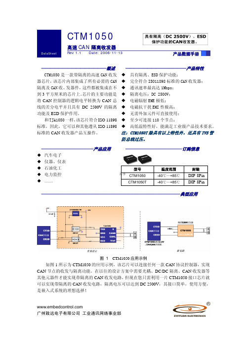
————————————产品应用 ◆ 汽车电子 ◆ 仪器、仪表 ◆ 石油化工 ◆ 电力监控 ◆ ……—————————————订购信息型号温度范围 封装CTM1050 -40℃—+85℃ DIP-8Pin CTM1050T-40℃—+85℃DIP-8Pin————————————————————————————————典型应用图 1 CTM1050应用示例如图1所示为CTM1050的应用示例,该芯片可以连接任何一款CAN 协议控制器,实现CAN 节点的收发与隔离功能。
在以往的设计方案中需要光耦、DC/DC 隔离、CAN 收发器等其他元器件才能实现带隔离的CAN 收发电路,但现在您只需利用一片CTM1050接口芯片就可以实现带隔离的CAN 收发电路,隔离电压可以达到DC 2500V ,其接口简单,使用方便,是嵌入式系统的理想选择!共享修订历史版本日期原因Rev X1 2006/6/8 内部制定初稿Rev 1.0 2006/6/16 第一次发布Rev 1.1 2006/11/11 数据手册升级共享目录销售信息 (2)技术支持 (2)1. 功能简介 (3)2. 引脚信息 (4)2.1 CTM1050引脚信息 (4)3. CTM1050特性参数 (5)3.1 参数列表 (5)3.2 电气特性 (5)3.3 绝缘特性 (6)4. 机械尺寸 (7)4.1 CTM1050机械尺寸 (7)5. 电路连接 (8)5.1 CTM1050电路连接 (8)6. 声明 (9)共享销售信息如果需要购买本产品,请在办公时间(星期一至五上午8:30~11:50;下午1:30~5:30;星期六上午8:30~11:50)拨打电话咨询广州致远电子有限公司。
美信深耕模拟市场 热门模数转换器(ADC)集锦

美信深耕模拟市场热门模数转换器(ADC)集锦
Maxim Integrated Products (美信公司)成立于1983年,以不断创造高品质的模拟工程解决方案为使命,在世界范围内为基于微处理器的电子产品客户提供增值服务。
在过去的23年里美信深耕模拟领域,开发并在市场上销售的IC超过5,400种―多于任何其他模拟半导体厂商,其中80%的产品由公司的设计工程师研发,针对美信在模拟半导体行业的影响,电子发烧友网细数了美信公司近月来推出的热门模数转换器(ADC),帮助工程师选取适合自己的解决方案。
MAX1302/MAX1303多量程、低功耗、16位、逐次逼近型模数转换器(ADC)
MAX1302/MAX1303多量程、低功耗、16位、逐次逼近型模数转换器(ADC),采用+5V单电源供电,具有高达115ksps的吞吐量。
独立的数字电源允许通过SPI™/QSPI™/MICROWIRE™兼容的串行接口与2.7V至5.25V系统连接。
局部关断模式可将电源电流降至1.3mA (典型值)。
完全关断模式则可将电源电流进一步降至1µA (典型值)。
MAX1302提供8路(单端)或4路(真差分)模拟输入通道。
MAX1303。
MAX485中文资料
本文是Maxim 正式英文资料的译文,Maxim 不对翻译中存在的差异或由此产生的错误负责。
请注意译文中可能存在文字组织或翻译错误,如需确认任何词语的准确性,请参考Maxim 提供的英文版资料。
索取免费样品和最新版的数据资料,请访问Maxim 的主页: 。
_______________________________概述MAX481、MAX483、MAX485、MAX487-MAX491以及MAX1487是用于RS-485与RS-422通信的低功耗收发器,每个器件中都具有一个驱动器和一个接收器。
MAX483、MAX487、MAX488以及MAX489具有限摆率驱动器,可以减小EMI ,并降低由不恰当的终端匹配电缆引起的反射,实现最高250k b p s 的无差错数据传输。
M A X 481、MAX485、MAX490、MAX491、MAX1487的驱动器摆率不受限制,可以实现最高2.5Mbps 的传输速率。
这些收发器在驱动器禁用的空载或满载状态下,吸取的电源电流在120(A 至500(A 之间。
另外,MAX481、MAX483与MAX487具有低电流关断模式,仅消耗0.1µA 。
所有器件都工作在5V 单电源下。
驱动器具有短路电流限制,并可以通过热关断电路将驱动器输出置为高阻状态,防止过度的功率损耗。
接收器输入具有失效保护特性,当输入开路时,可以确保逻辑高电平输出。
MAX487与MAX1487具有四分之一单位负载的接收器输入阻抗,使得总线上最多可以有128个M A X 487/MAX1487收发器。
使用MAX488-MAX491可以实现全双工通信,而MAX481、MAX483、MAX485、MAX487与MAX1487则为半双工应用设计。
_______________________________应用低功耗RS-485收发器低功耗RS-422收发器电平转换器用于EMI 敏感应用的收发器工业控制局域网____________________下一代器件的特性♦容错应用MAX3430: ±80V 故障保护、失效保护、1/4单位负载、+3.3V 、RS-485收发器MAX3440E-MAX3444E: ±15kV ESD 保护、±60V 故障保护、10Mbps 、失效保护、RS-485/J1708收发器♦对于空间受限应用MAX3460-MAX3464: +5V 、失效保护、20Mbps 、Profibus RS-485/RS-422收发器MAX3362: +3.3V 、高速、RS-485/RS-422收发器,采用SOT23封装MAX3280E-MAX3284E: ±15kV ESD 保护、52Mbps 、+3V 至+5.5V 、SOT23、RS-485/RS-422、真失效保护接收器MAX3293/MAX3294/MAX3295: 20Mbps 、+3.3V 、SOT23、RS-485/RS-422发送器♦对于多通道收发器应用MAX3030E-MAX3033E: ±15kV ESD 保护、+3.3V 、四路RS-422发送器♦对于失效保护应用MAX3080-MAX3089: 失效保护、高速(10Mbps)、限摆率RS-485/RS-422收发器♦对于低电压应用MAX3483E/MAX3485E/MAX3486E/MAX3488E/MAX3490E/MAX3491E: +3.3V 供电、±15kV ESD 保护、12Mbps 、限摆率、真正的RS-485/RS-422收发器MAX481/MAX483/MAX485/MAX487–MAX491/MAX1487低功耗、限摆率、RS-485/RS-422收发器_____________________________________________________________________选择表19-0122; Rev 8; 10/03定购信息在本资料的最后给出。
TJA1050中文资料_数据手册_参数

2003年10月22日 4飞利浦半导体产品SPECI FI CATION高速CAN收发器 TJA1050功能说明 TJA1050是CAN协议之间的接口控制器和物理 总线.它主要用于使用波特率的高速汽车应用 60 KBAUD到1 MBAUD.它提供差分传输总线能力和差分接收器能力 CAN协议控制器.它完 全兼容 “ISO 11898”标准.限流电路保护发射机输出阶段由意外短路造成的损坏虽然电力正常或负电源电压在这种故障状态下功耗会 增加.热保护电路可保护IC免受损坏通过关闭发射机如果结温超过约165的值 C.因为发射机消耗大部分功率和功率 IC的耗散和温度降 低.所有其他 IC功能继续运行.发射机关闭状态当引脚TXD变为高电平时复位.热保护当总线短路时尤其需要电路. CANH和CANL引脚不 受汽车的保护电瞬变(根据 “ISO 7637”;参见图4).控制引脚S允许选择两种工作模式:高速模式或静音模式.高速模式是正常的操作 模式,并且是通过将引脚S连接到地面来选择.这是默认设置模式,如果引脚S未连接.但是,要确保EMI在仅使用高速应用的应用中表现 出色模式,建议将引脚S连接到地面.在静音模式下,发射器被禁用.所有其他 IC功能继续运行.无声模式是 通过连接引脚S到V CC进行 选择 ,可用于防止网络通信被阻塞,到期到一个失控的CAN控制器. “TXD主导超时”定时器电路阻止总线线路被驱动到永久主导状 态(阻塞)所有网络通信)如果引脚TXD被强制由硬件和/或软件永久为低应用失败.定时器由否定触发边沿TXD引脚.如果持续低电平 的话 TXD引脚超过内部定时器值,发送器为残疾,驾驶巴士进入隐性状态.定时器由引脚TXD上的上升沿复位.表格1 CAN收发器的功 能表; X =不在乎 V CC TXD小号 CANH CANL总线状态 RXD 4.75 V至5.25 V低低(或 FL替罪羊)高低优势低 4.75 V至5.25 V X高 0.5V CC 0.5V CC隐性高 4.75 V至5.25 V高( 飞利浦半导体产品SPECI FI CATION高速CAN收发器 TJA1050手册,全页面宽度 50 80 0 020三十 10 MGT231 40 F(MHZ) 20 40 60一个 (D B μV)图9高达50 MHZ的典型电磁发射(峰值幅度测量).数据速率为500千比特/秒.手册,全页面宽度 10 80 0 04 6 2 MGT233 8 F(MHZ) 20 40 60一个 (D B μV)图10高达10 MHZ的典型电磁发射(峰值幅度测量和峰值包络振幅).数据速率为500千比特/秒. 图1方框图.钉扎符号销描述 TXD 1传输数据输入;读入数据从CAN控制器到总线线路司机 GND 2地面 V CC 3电源电压 RXD 4接收数据输 出;读出来从公交线路到公交车的数据 CAN控制器 V REF五参考电压输出 CANL 6低级CAN总线 CANH 7高级CAN总线小号 8选择高速 模式的输入或静音模式手册,HALFPAGE 1 2 3 4 8 7 6五 MGS375 TJA1050T小号 CANH GND CANL VREF RXD VCC TXD图2引脚配置
MAXIM公司部分IC芯片应用简介
MAXIM公司部分IC芯片应用简介
王淑霞
【期刊名称】《集成电路应用》
【年(卷),期】2001(000)004
【摘要】1 节省空间和功耗的5阶滤波器芯片——
MAX7409/MAX7410/MAX7413/MAX7414 新型5阶贝塞尔、巴特沃斯低通开关电容滤波器系列产品,采用8脚uMAX和DIP封装。
美国MAXIM公司专有的,比8脚DIP封装尺寸小80%的uMAX封装使其成为业界最小的5阶开关电容滤波器。
【总页数】2页(P54-55)
【作者】王淑霞
【作者单位】胶南市大场西柳沟村电子开发部,266414
【正文语种】中文
【相关文献】
1."腐蚀控制工程全生命周期理论、应用和标准化"简介及"世界各国专家高度评价的部分"摘要 [J], 中国工业防腐蚀技术协会
2.FIB-SEM双束技术简介及其部分应用介绍 [J], 付琴琴;单智伟
3.MAXIM公司部分IC芯片应用简介(续一) [J], 王淑霞
4.冷链技术简介
——第Ⅴ部分渔船应用设备 [J], Paul de LARMINAT;邵月月;范薇;王亚薇;田甜5.“运动学习”方法简介及在康复中的应用第二部分:反馈和训练方式的应用(简译) [J], ChristopherAZaino;黄真
因版权原因,仅展示原文概要,查看原文内容请购买。
Maxim Integrated产品介绍:16位MAXQ微处理器说明书
most demanding needsM icrocontrollerPrecision AnalogSecurityLow-Power OperationIndustry's best securitytechnology to protect money, software IP, or secret dataWorld-class low power and high performance to make today’s battery-powered equipment run faster and longerPrecision analog to support complex, mixed-signal embedded applicationsMaxim is a registered trademark of Maxim Integrated Products, Inc. © 2009 Maxim Integrated Products, Inc. All rights reserved.Give your customer months of extra time 16-bit MAXQ® µCs greatly extend battery life in portable equipment The MAXQ610 is designed for low-cost, high-performance, battery-powered applications. This 16-bit, RISC-basedconsumption. Its anticloning features and secure MMU enable you to protect your IPMicrocontroller• 16-bit MAXQ RISC core• 64KB flash memory, 2KB SRAM• Ultra-low supply current• Active mode: 3.75mA at 12MHz• Stop mode: 200nA (typ), 2.0µA (max)• Wide, 1.7V to 3.6V operating voltage range • IP protection• Secure MMU supports multiple privilegemaster/slave • Two 16-bit timers/counters• 8kHz nanoring functions as programmable wakeup timerMaxim’s line of low-power µCs are designed to specifically address the most pressing demands on today’s battery-powered electronics. These µCs extend battery life, enable advanced feature sets through higher performance and integration, and allow small form factors with reduced footprint solutions.KEYPAD MATRIXGPIOsSECURE, 16-BIT MAXQ COREMAXQ610Supports capacitive touch or pushbutton matrixDirectly drive IR transmission up to 25mA Operates down to 1.7V—ideal for 2AA/AAA batteries!Learning or fixed-function remoteApplication focus: Universal remote controlsMaxim now offers the widest range of devices with integrated infrared drivers and timers for IR communications, due to its acquisition of the Classic IR and Crimzon ® lines from Zilog. Combined with the unmatched ability to extend battery life and integrate multiple features, Maxim’s µCs are the ideal choice for remote-control designs.Need a PCI 2.0 silicon provider?Look no furtherThe universal secure integrated platform professional IC (USIP™ PRO) is the industry’s highest performance, most secure 32-bit MIPS® microprocessor. It supports Linux® operating systems and enables next-generation EMV® and PCI PED-compliant applications.With the acquisition of Innova Card and the secure transaction Zatara® product line from Zilog, the secure µC product line from Maxim now offers the broadest range of products for the high-security, financial-terminal market. Combining Maxim’s high-security silicon technology, Innova Card’s application knowledge and support, and Zatara’s impressive integration, Maxim now has the best knowledge, technology, and products to support the most demanding security applications.Secure microcontrollersIndustry’s fastest, most secure ARM®-based SoC µC meets PCI 2.0 requirementsIntegrates security and application-management functions needed for the next generation of trusted devicesEXTERNAL BUS CONTROLLERLowest pin count, secure µC for financial-terminal applicationsSmallest footprint available for applications that require a high level of physical and logical security32-bit µC integrates security supervisor and cryptographic functionsIdeal for any application that requires PCI, FIPS 140-2, Common Criteria, or other security certificationsElectricity meter or power analyzer? Electricity-metering AFE combines watt-hour and VAR-hourmeasurement with sophisticated power analysisThe MAXQ3180 AFE is deceptively simple: an 8-channel ADC combined with asingle-cycle, 16-bit RISC core to create a complete electricity-metering AFE. But whatsets the MAXQ3180 apart from other AFE devices is the set of algorithms embeddedalso aAlphanumeric LCD for display of many metercharacteristicsMAXQ2000 supervisoryMCU with JTAG programming and debugThree voltage and current-phase inputs,plus connections formeter pulses and EIA-485 communicationInfrared communicationfor contactless readingand configurationRS-232 for readingand configurationduring bench test andcalibrationTransformer-basedcurrent sensing providesbetter than class 0.5accuracy (0.5% over theoperating range)AB214MAXQ3180 reference designHow the PCB is routed can make the difference between an exceptional electricity meter design and a merely acceptable design. Maxim has years of experience in successful analog layout and can help you design an exceptional electricity meter on your first pass. Our engineering team can review your MAXQ-based design to ensure your product’s performance.Metering microcontrollers9Innovative chipset solution reduces BOM in polyphase energy metersKeeps phases isolated without bulky, expensive current transformersis keeping the phases isolated from one another and from external connections. and its Manchester-encoded inexpensive capacitors rather than bulky current transformers without compromising accuracy U S E R M A X Q C O R E64KB CODE FLASHSERIAL (2)TIMERS (2)GPIO RTC2KB DATA RAM MAXQ3108USER CORESource code and schematics availableDesign files for the MAXQ3108/DS8102 reference design meter are available. These files include schematics, bills of material, and complete source code written in C. In addition, our support team can help you integrate the MAXQ3108 and DS8102 into your own design. Contact your sales representative for more details.Metering microcontrollersGive your customers a steady hand16-bit µC has optical image stabilization to self-correct for higher image qualityThe MAXQ8913 provides a complete dual-axis optical image stabilization (OIS) solution for digital and cell-phone cameras. This µC integrates data converters, operational amplifiers, and various communications ports, making it ideal for all-in-one servo loop control by supporting both voice-coil and stepper-motor applications.GYRO GYROTEMP SENSORAMPACTUATORSENSORPITCHLENS MODULEYAWAMP ACTUATORSENSORHand vibrations in pitch and yaw axes are captured by gyros Sensors feed lens adjustment data back to MAXQ8913l ee n ce d e s i g nOP AMPSThe seamless integration of analog peripherals with the 16-bit, single-cycle MAXQ RISC core and various digital peripherals makes our mixed-signal µCs' performance-to-power characteristics the industry’s best among 16-bit µCs.Mixed-signal microcontrollers11TEMP SENSOR 12-BIT DACMAXQ7666MAXQ7670MAXQ7666MAXQ7670MAXQ PROCESSORSPILIN UART10-/12-BIT ADC16 x 16 MACCAN 2.0B1 OR 3TIMERSGPIO JTAGPGAM U XM U XMAXQ7666MAXQ7670Revolutionary integration enables small sensor conditionersIntegrated µC and high-performance analog circuitry reduce footprint by up to 80%, decrease cost, improve signal integrity, and accelerate sensor developmentThe MAXQ7666/MAXQ7670 are complete, integrated solutions for processing small-amplitude analog-input signals, such as those from anisotropic magnetoresistive (AMR) or other sensors producing small, sensor-output signals. Applications include automotive steering-angle and torque sensors, CAN-based automotive and industrial sensors, and industrial control.Features• Up to 8 single-ended or 4 differential ADC channels with on-chip input multiplexer • High-precision PGA• Fast, 16-bit MAXQ µC with 16 x 16 MAC• Flexible CAN 2.0B, LIN/UART, and SPI interfacesBenefits• Reduce BOM cost by 30% to 40%• Allow efficient, on-chip numerical computation • Include a variety of interfaces for automotive and industrial usePartFlash Size (KB)Temp Range(°C)PackageMAXQ7666BATM+*16 (8k x 16)-40 to +12548 TQFN-EP (7 x 7)MAXQ7670ATL+64 (32k x 16)40 TQFN-EP (6 x 6)Small Package (mm x mm)*Contact factory for availability.The continuing demands to enhance automotive safety and improve fuel economy are driving the need for increased electronics content. This, in turn, is increasing the number of µCs and sensors required to meet these demands. Maxim enables automotive electronics suppliers to meet the demands for collision detection and drive-by-wire steering by integrating the analog electronics with the µC, thus providing an intelligent interface to the sensor.Microcontroller-based sensor interfacesYes, we make that...。
CAN收发器—TJA1040与TJA1050对比报告

CAN 收发器 TJA1040与TJA1050对比报告1.简介CAN总线,它是一种多主方式的串行通讯总线,基本设计规范要求有较高的位速率,高抗干扰性,而且能够检测出产生的任何错误。
信号传输距离达到10Km时,仍然可提供高达5Kbps的数据传输速率。
由于CAN串行通讯总线具有这些特性,它很自然的在汽车、制造业以及航空工业中受到广泛应用。
与CAN协议相关的芯片主要有两类,一类是:CAN控制器芯片,一类是:CAN收发器芯片,如TJA1040,TJA1050。
CAN控制器用于实现CAN总线的协议底层以及数据链路层,用于生成CAN帧并以二进制码流的方式发送,在此过程中进行位填充、添加CRC校验、应答检测等操作;将接收到的二进制码流进行解析并接收,在此过程中进行收发比对、去位填充、执行CRC校验等操作。
此外还需要进行冲突判断、错误处理等诸多任务。
图1 CAN收发器在CAN总线应用系统中的位置CAN收发器是CAN协议控制器和物理总线(双绞线)之间的接口,用于将二进制码流转换为差分信号发送,将差分信号转换为二进制码流接收,主要实现逻辑电平与“显性”,“隐性”的转换。
它可以为总线提供差动的发送功能,为控制器提供差动的接收功能,是CAN-Bus网络中的必须设备。
常见的CAN控制器芯片与CAN收发器芯片型号参见第5部分。
目前还没有看到把CAN控制器和CAN收发器集成在一起的CAN协议芯片,目前主要是独立的CAN控制器,独立的CAN接收器,集成CAN控制器的微处理器三类。
因为CAN收发器和CAN控制器之间有时需要添加隔离单元。
总结:CAN通信协议主要有CAN控制器完成,CAN控制器主要有实现CAN协议的电路和实现与微处理器接口的电路组成。
CAN收发器在CAN总线应用系统中的位置如下图所示。
图2 CAN收发器的典型应用电路TJA1050 的设计采用了先进的绝缘硅SOI技术进行处理,以及最新的EMC技术,所以TJA1050具有优良的EMC性能。
MAX10_FPGA_datasheet_ch
DC 输入电压 每个管脚的 DC 输出电流 存储温度 工作结温
–0.5 –25 –65 –40
4.12 25 150 125
V mA °C °C
11.4 年期限的跳变期间允许的最大过冲
跳变期间,输入信号可能过冲到下表中列出的电压,对于小于 100 mA 的输入电流和短于 20 ns 的周期可能下冲到–2.0 V。 所允许的最大过冲持续时间定义为高时间与器件生命周期的百分比。一个 DC 信号相当于 100%占空比。 例如:一个过冲到 4.17 V 的信号只能在 4.17 V 上持续器件生命周期的~11.7%。对于 11.4 年的器件生命周期,此过冲持续时间为 1.33 年。
© 2016 Intel Corporation. All rights reserved. Intel, the Intel logo, Altera, Arria, Cyclone, Enpirion, MAX, Megacore, NIOS, Quartus and Stratix words and logos are trademarks of Intel Corporation in the US and/or other countries. Other marks and brands may be claimed as the property of others. Intel warrants performance of its FPGA and semiconductor products to current specifications in accordance with Intel's standard warranty, but reserves the right to make changes to any products and services at any time without notice. Intel assumes no responsibility or liability arising out of the application or use of any information, product, or service described herein except as expressly agreed to in writing by Intel. Intel customers are advised to obtain the latest version of device specifications before relying on any published information and before placing orders for products or services.
IC datasheet pdf-MAXQ2010评估套件

BIT 3 COM3 1A 1H 2A 2H 3A 3H 4A 4H 5A 5H 6A 6H 7A 7H 8A 8H
BIT 2 COM2 1B 1G 2B 2G 3B 3G 4B 4G 5B 5G 6B 6G 7B 7G 8B 8G
BIT 1 COM1 1C 1N 2C 2N 3C 3N 4C 4N 5C 5N 6C 6N 7C 7N 8C 8N
QTY
DESCRIPTION 100nF ±10%, 10V ceramic capacitors (0805) Murata GRM219R71C104KA01D 10nF ±5%, 10V ceramic capacitors (0805) Murata GRM21BR72A103KA01L 22pF ±5%, 10V ceramic capacitors (0805) Murata GRM2195C2A220JZ01D 4.7μF ±10%, 10V ceramic capacitors (0805) Murata GRM219R61A475KE19D 10μF ±10%, 10V capacitors (0805) Murata GRM21BR61A106KE19L Empty capacitor footprint (0805) 1μF ±10%, 10V ceramic capacitors (0805) Murata GRM21BR71C105KA01L Green surface-mount LEDs Lumex SML-LX0805SUGC-TR Red surface-mount LED Lumex SML-LX0805SIC-TR
BIT 6 COM2 1F 1J 2F 2J 3F 3J 4F 4J 5F 5J 6F 6J 7F 7J 8F 8J
CTM1050

CTM1050———————————————概述CTM1050是一款带隔离的高速CAN 收发器芯片,该芯片内部集成了所有必需的CAN 隔离及CAN 收、发器件,这些都被集成在不到3平方厘米的芯片上。
芯片的主要功能是将CAN 控制器的逻辑电平转换为CAN 总线的差分电平并且具有DC 2500V 的隔离功能及ESD 保护作用。
该芯片符合ISO 11898标准,因此,它可以和其他遵从ISO 11898标准的CAN 收发器产品互操作。
——————————————产品特性 具有隔离、ESD 保护功能;完全符合ISO11898标准的CAN 收发器; 通讯速率最高达1Mbps; 隔离电压:DC 2500V; 电磁辐射EME 极低; 电磁抗干扰EMI 性极高; 无需外加元件可直接使用; 至少可连接110个节点;高低温特性好,能满足工业级产品技术要求。
注:CTM1050T 除具有以上特性外,还具有TVS 管 防总线过压。
————————————产品应用 ◆ 汽车电子 ◆ 仪器、仪表 ◆ 石油化工 ◆ 电力监控 ◆ ……—————————————订购信息型号 温度范围 封装CTM1050 -40℃—+85℃ DIP-8Pin CTM1050T-40℃—+85℃DIP-8Pin————————————————————————————————典型应用图 1 CTM1050应用示例如图1所示为CTM1050的应用示例,该芯片可以连接任何一款CAN 协议控制器,实现CAN 节点的收发与隔离功能。
在以往的设计方案中需要光耦、DC/DC 隔离、CAN 收发器等其他元器件才能实现带隔离的CAN 收发电路,但现在您只需利用一片CTM1050接口芯片就可以实现带隔离的CAN 收发电路,隔离电压可以达到DC 2500V ,其接口简单,使用方便,是嵌入式系统的理想选择!修订历史版本日期原因Rev X1 2006/6/8 内部制定初稿Rev 1.0 2006/6/16 第一次发布Rev 1.1 2006/11/11 数据手册升级Rev 1.20 2006/06/30 数据手册模版升级目录1. 功能简介 (2)2. 引脚信息 (3)2.1 CTM1050引脚信息 (3)3. CTM1050特性参数 (4)3.1 参数列表 (4)3.2 电气特性 (4)3.3 绝缘特性 (5)4. 机械尺寸 (6)4.1 CTM1050机械尺寸 (6)5. 电路连接 (7)5.1 CTM1050电路连接 (7)5.2 网络拓扑结构 (7)6. 声明 (8)7. 销售与服务网络 (1)1.功能简介CTM1050芯片采用全灌封工艺,内部集成CAN-bus所必须的收发电路,完全电气隔离电路,隔离电压(DC2500V)。
MAX系列芯片速查

MAXIM/DALLAS 中文数据资料DS12CR887, DS12R885, DS12R887 RTC,带有恒压涓流充电器DS1870 LDMOS RF功放偏置控制器DS1921L-F5X Thermochron iButtonDS1923 温度/湿度记录仪iButton,具有8kB数据记录存储器DS1982, DS1982-F3, DS1982-F5 1k位只添加iButton?DS1990A 序列号iButtonDS1990R, DS1990R-F3, DS1990R-F5 序列号iButtonDS1991 多密钥iButtonDS2129 LVD SCSI 27线调节器DS2401 硅序列号DS2406 双通道、可编址开关与1k位存储器DS2408 1-Wire、8通道、可编址开关DS2411 硅序列号,带有VCC输入DS2413 1-Wire双通道、可编址开关DS2430A 256位1-Wire EEPROMDS2431 1024位、1-Wire EEPROMDS2480B 串行、1-Wire线驱动器,带有负荷检测DS2482-100 单通道1-Wire主控制器DS2482-100 勘误表PDF: 2482-100A2DS2482-800, DS2482S-800 八通道1-Wire主控制器DS2482-800 勘误表PDF: 2482-800A2DS2502 1k位只添加存储器DS2505 16k位只添加存储器DS28E04-100 4096位、可寻址、1-Wire EEPROM,带有PIO DS3170DK DS3/E3单芯片收发器开发板DS3231, DS3231S 高精度、I2C集成RTC/TCXO/晶振DS33Z44 四路以太网映射器DS3902 双路、非易失、可变电阻器,带有用户EEPROMDS3906 三路、非易失、小步长调节可变电阻与存储器DS3984 4路冷阴极荧光灯控制器DS4302 2线、5位DAC,提供三路数字输出DS80C400-KIT DS80C400评估套件DS80C410, DS80C411 具有以太网和CAN接口的网络微控制器DS80C410 勘误表PDF: 80C410A1DS89C430, DS89C440, DS89C450 超高速闪存微控制器DS89C430 勘误表PDF: 89C430A2DS89C440 勘误表PDF: 89C440A2DS89C450 勘误表PDF: 89C450A2DS89C430 勘误表PDF: 89C430A3DS89C440 勘误表PDF: 89C440A3DS89C450 勘误表PDF: 89C450A3DS89C430 勘误表PDF: 89C430A5DS89C440 勘误表PDF: 89C440A5DS89C450 勘误表PDF: 89C450A5DS9090K 1-Wire器件评估板, B版DS9097U-009, DS9097U-E25, DS9097U-S09 通用1-Wire COM端口适配器DS9490, DS9490B, DS9490R USB至1-Wire/iButton适配器MAX1034, MAX1035 8/4通道、±VREF多量程输入、串行14位ADCMAX1072, MAX1075 1.8Msps、单电源、低功耗、真差分、10位ADCMAX1076, MAX1078 1.8Msps、单电源供电、低功耗、真差分、10位ADC,内置电压基准MAX1146, MAX1147, MAX1148, MAX1149 多通道、真差分、串行、14位ADC MAX1149EVKIT MAX1149评估板/评估系统MAX1220, MAX1257, MAX1258 12位、多通道ADC/DAC,带有FIFO、温度传感器和GPIO端口MAX1224, MAX1225 1.5Msps、单电源、低功耗、真差分、12位ADCMAX1258EVKIT MAX1057, MAX1058, MAX1257, MAX1258评估板/评估系统MAX1274, MAX1275 1.8Msps、单电源、低功耗、真差分、12位ADCMAX13000E, MAX13001E, MAX13002E, MAX13003E, MAX13004E, MAX13005E 超低电压电平转换器MAX1302, MAX1303 8/4通道、±VREF多量程输入、串行16位ADCMAX1304, MAX1305, MAX1306, MAX1308, MAX1309, MAX1310, MAX1312, MAX1313, MAX1314 8/4/2通道、12位、同时采样ADC,提供±10V、±5V或0至+5V 模拟输入范围MAX13050, MAX13052, MAX13053, MAX13054 工业标准高速CAN收发器,具有±80V故障保护MAX13080E, MAX13081E, MAX13082E, MAX13083E, MAX13084E, MAX13085E, MAX13086E, MAX13087E, MAX13088E, MAX13089E +5.0V、±15kV ESD保护、失效保护、热插拔、RS-485/RS-422收发器MAX13101E, MAX13102E, MAX13103E, MAX13108E 16通道、带有缓冲的CMOS 逻辑电平转换器MAX1334, MAX1335 4.5Msps/4Msps、5V/3V、双通道、真差分10位ADCMAX1336, MAX1337 6.5Msps/5.5Msps、5V/3V、双通道、真差分8位ADCMAX13481E, MAX13482E, MAX13483E ±15kV ESD保护USB收发器, 外部/内部上拉电阻MAX1350, MAX1351, MAX1352, MAX1353, MAX1354, MAX1355, MAX1356, MAX1357 双路、高端、电流检测放大器和驱动放大器MAX1450 低成本、1%精确度信号调理器,用于压阻式传感器MAX1452 低成本、精密的传感器信号调理器MAX1487, MAX481, MAX483, MAX485, MAX487, MAX488, MAX489, MAX490, MAX491 低功耗、限摆率、RS-485/RS-422收发器MAX1492, MAX1494 3位半和4位半、单片ADC,带有LCD驱动器MAX1494EVKIT MAX1493, MAX1494, MAX1495评估板/评估系统MAX1497, MAX1499 3位半和4位半、单片ADC,带有LED驱动器和μC接口MAX1499EVKIT MAX1499评估板/评估系统MAX15000, MAX15001 电流模式PWM控制器, 可调节开关频率MAX1515 低电压、内置开关、降压/DDR调节器MAX1518B TFT-LCD DC-DC转换器, 带有运算放大器MAX1533, MAX1537 高效率、5路输出、主电源控制器,用于笔记本电脑MAX1533EVKIT MAX1533评估板MAX1540A, MAX1541 双路降压型控制器,带有电感饱和保护、动态输出和线性稳压器MAX1540EVKIT MAX1540评估板MAX1551, MAX1555 SOT23、双输入、USB/AC适配器、单节Li+电池充电器MAX1553, MAX1554 高效率、40V、升压变换器,用于2至10个白光LED驱动MAX1556, MAX1557 16μA IQ、1.2A PWM降压型DC-DC转换器MAX1556EVKIT MAX1556EVKIT评估板MAX1558, MAX1558H 双路、3mm x 3mm、1.2A/可编程电流USB开关,带有自动复位功能MAX1586A, MAX1586B, MAX1586C, MAX1587A, MAX1587C 高效率、低IQ、带有动态内核的PMIC,用于PDA和智能电话MAX16801A/B, MAX16802A/B 离线式、DC-DC PWM控制器, 用于高亮度LED驱动器MAX1858A, MAX1875A, MAX1876A 双路180°异相工作的降压控制器,具有排序/预偏置启动和PORMAX1870A 升/降压Li+电池充电器MAX1870AEVKIT MAX1870A评估板MAX1874 双路输入、USB/AC适配器、1节Li+充电器,带OVP与温度调节MAX1954A 低成本、电流模式PWM降压控制器,带有折返式限流MAX1954AEVKIT MAX1954A评估板MAX19700 7.5Msps、超低功耗模拟前端MAX19700EVKIT MAX19700评估板/评估系统MAX19705 10位、7.5Msps、超低功耗模拟前端MAX19706 10位、22Msps、超低功耗模拟前端MAX19707 10位、45Msps、超低功耗模拟前端MAX19708 10位、11Msps、超低功耗模拟前端MAX2041 高线性度、1700MHz至3000MHz上变频/下变频混频器,带有LO缓冲器/开关MAX2043 1700MHz至3000MHz高线性度、低LO泄漏、基站Rx/Tx混频器MAX220, MAX222, MAX223, MAX225, MAX230, MAX231, MAX232, MAX232A, MAX233, MAX233A, MAX234, MAX235, MAX236, MAX237, MAX238, MAX239, MAX240, MAX241, MAX242, MAX243, MAX244, MAX245, MAX246, MAX247, MAX248, MAX249 +5V供电、多通道RS-232驱动器/接收器MAX2335 450MHz CDMA/OFDM LNA/混频器MAX2370 完备的、450MHz正交发送器MAX2370EVKIT MAX2370评估板MAX2980 电力线通信模拟前端收发器MAX2986 集成电力线数字收发器MAX3013 +1.2V至+3.6V、0.1μA、100Mbps、8路电平转换器MAX3205E, MAX3207E, MAX3208E 双路、四路、六路高速差分ESD保护ICMAX3301E, MAX3302E USB On-the-Go收发器与电荷泵MAX3344E, MAX3345E ±15kV ESD保护、USB收发器,UCSP封装,带有USB检测MAX3394E, MAX3395E, MAX3396E ±15kV ESD保护、大电流驱动、双/四/八通道电平转换器, 带有加速电路MAX3535E, MXL1535E +3V至+5V、提供2500VRMS隔离的RS-485/RS-422收发器,带有±15kV ESD保护MAX3570, MAX3571, MAX3573 HI-IF单芯片宽带调谐器MAX3643EVKIT MAX3643评估板MAX3645 +2.97V至+5.5V、125Mbps至200Mbps限幅放大器,带有信号丢失检测器MAX3654 47MHz至870MHz模拟CATV互阻放大器MAX3654EVKIT MAX3654评估板MAX3657 155Mbps低噪声互阻放大器MAX3658 622Mbps、低噪声、高增益互阻前置放大器MAX3735, MAX3735A 2.7Gbps、低功耗、SFP激光驱动器MAX3737 多速率激光驱动器,带有消光比控制MAX3737EVKIT MAX3737评估板MAX3738 155Mbps至2.7Gbps SFF/SFP激光驱动器,带有消光比控制MAX3744, MAX3745 2.7Gbps SFP互阻放大器,带有RSSIMAX3744EVKIT, MAX3745EVKIT MAX3744, MAX3745评估板MAX3748, MAX3748A, MAX3748B 紧凑的、155Mbps至4.25Gbps限幅放大器MAX3785 6.25Gbps、1.8V PC板均衡器MAX3787EVKIT MAX3787评估板MAX3793 1Gbps至4.25Gbps多速率互阻放大器,具有光电流监视器MAX3793EVKIT MAX3793评估板MAX3805 10.7Gbps自适应接收均衡器MAX3805EVKIT MAX3805评估板MAX3840 +3.3V、2.7Gbps双路2 x 2交叉点开关MAX3841 12.5Gbps CML 2 x 2交叉点开关MAX3967 270Mbps SFP LED驱动器MAX3969 200Mbps SFP限幅放大器MAX3969EVKIT MAX3969评估板MAX3982 SFP铜缆预加重驱动器MAX3983 四路铜缆信号调理器MAX3983EVKIT MAX3983评估板MAX3983SMAEVKIT MAX3983 SMA连接器评估板MAX4079 完备的音频/视频后端方案MAX4210, MAX4211 高端功率、电流监视器MAX4210EEVKIT MAX4210E、MAX4210A/B/C/D/F评估板MAX4211EEVKIT MAX4211A/B/C/D/E/F评估板MAX4397 用于双SCART连接器的音频/视频开关MAX4397EVKIT MAX4397评估系统/评估板MAX4411EVKIT MAX4411评估板MAX4729, MAX4730 低电压、3.5、SPDT、CMOS模拟开关MAX4754, MAX4755, MAX4756 0.5、四路SPDT开关,UCSP/QFN封装MAX4758, MAX4759 四路DPDT音频/数据开关,UCSP/QFN封装MAX4760, MAX4761 宽带、四路DPDT开关MAX4766 0.075A至1.5A、可编程限流开关MAX4772, MAX4773 200mA/500mA可选的限流开关MAX4795, MAX4796, MAX4797, MAX4798 450mA/500mA限流开关MAX4826, MAX4827, MAX4828, MAX4829, MAX4830, MAX4831 50mA/100mA 限流开关, 带有空载标记, μDFN封装MAX4832, MAX4833 100mA LDO,带有限流开关MAX4834, MAX4835 250mA LDO,带有限流开关MAX4836, MAX4837 500mA LDO,带有限流开关MAX4838A, MAX4840A, MAX4842A 过压保护控制器,带有状态指示FLAGMAX4850, MAX4850H, MAX4852, MAX4852H 双路SPDT模拟开关,可处理超摆幅信号MAX4851, MAX4851H, MAX4853, MAX4853H 3.5/7四路SPST模拟开关,可处理超摆幅信号MAX4854 7四路SPST模拟开关,可处理超摆幅信号MAX4854H, MAX4854HL 四路SPST、宽带、信号线保护开关MAX4855 0.75、双路SPDT音频开关,具有集成比较器MAX4864L, MAX4865L, MAX4866L, MAX4867, MAX4865, MAX4866 过压保护控制器,具有反向保护功能MAX4880 过压保护控制器, 内置断路开关MAX4881, MAX4882, MAX4883, MAX4884 过压保护控制器, 内部限流, TDFN封装MAX4901, MAX4902, MAX4903, MAX4904, MAX4905 低RON、双路SPST/单路SPDT、无杂音切换开关, 可处理负电压MAX4906, MAX4906F, MAX4907, MAX4907F 高速/全速USB 2.0开关MAX5033 500mA、76V、高效率、MAXPower降压型DC-DC变换器MAX5042, MAX5043 双路开关电源IC,集成了功率MOSFET和热插拔控制器MAX5058, MAX5059 可并联的副边同步整流驱动器和反馈发生器控制ICMAX5058EVKIT MAX5051, MAX5058评估板MAX5062, MAX5062A, MAX5063, MAX5063A, MAX5064, MAX5064A, MAX5064B 125V/2A、高速、半桥MOSFET驱动器MAX5065, MAX5067 双相、+0.6V至+3.3V输出可并联、平均电流模式控制器MAX5070, MAX5071 高性能、单端、电流模式PWM控制器MAX5072 2.2MHz、双输出、降压或升压型转换器,带有POR和电源失效输出MAX5072EVKIT MAX5072评估板MAX5074 内置MOSFET的电源IC,用于隔离型IEEE 802.3af PD和电信电源MAX5078 4A、20ns、MOSFET驱动器MAX5084, MAX5085 65V、200mA、低静态电流线性稳压器, TDFN封装MAX5088, MAX5089 2.2MHz、2A降压型转换器, 内置高边开关MAX5094A, MAX5094B, MAX5094C, MAX5094D, MAX5095A, MAX5095B, MAX5095C 高性能、单端、电流模式PWM控制器MAX5128 128抽头、非易失、线性变化数字电位器, 采用2mm x 2mm μDFN封装MAX5417, MAX5417L, MAX5417M, MAX5417N, MAX5417P, MAX5418, MAX5419 256抽头、非易失、I2C接口、数字电位器MAX5417LEVKIT MAX5417_, MAX5418_, MAX5419_评估板/评估系统MAX5477, MAX5478, MAX5479 双路、256抽头、非易失、I2C接口、数字电位器MAX5478EVKIT MAX5477/MAX5478/MAX5479评估板/评估系统MAX5490 100k精密匹配的电阻分压器,SOT23封装MAX5527, MAX5528, MAX5529 64抽头、一次性编程、线性调节数字电位器MAX5820 双路、8位、低功耗、2线、串行电压输出DACMAX5865 超低功耗、高动态性能、40Msps模拟前端MAX5920 -48V热插拔控制器,外置RsenseMAX5921, MAX5939 -48V热插拔控制器,外置Rsense、提供较高的栅极下拉电流MAX5932 正电源、高压、热插拔控制器MAX5932EVKIT MAX5932评估板MAX5936, MAX5937 -48V热插拔控制器,可避免VIN阶跃故障,无需RSENSE MAX5940A, MAX5940B IEEE 802.3af PD接口控制器,用于以太网供电MAX5940BEVKIT MAX5940B, MAX5940D评估板MAX5941A, MAX5941B 符合IEEE 802.3af标准的以太网供电接口/PWM控制器,适用于用电设备MAX5945 四路网络电源控制器,用于网络供电MAX5945EVKIT, MAX5945EVSYS MAX5945评估板/评估系统MAX5953A, MAX5953B, MAX5953C, MAX5953D IEEE 802.3af PD接口和PWM控制器,集成功率MOSFETMAX6640 2通道温度监视器,提供双路、自动PWM风扇速度控制器MAX6640EVKIT MAX6640评估系统/评估板MAX6641 兼容于SMBus的温度监视器,带有自动PWM风扇速度控制器MAX6643, MAX6644, MAX6645 自动PWM风扇速度控制器,带有过温报警输出MAX6678 2通道温度监视器,提供双路、自动PWM风扇速度控制器和5个GPIOMAX6695, MAX6696 双路远端/本地温度传感器,带有SMBus串行接口MAX6877EVKIT MAX6877评估板MAX6950, MAX6951 串行接口、+2.7V至+5.5V、5位或8位LED显示驱动器MAX6966, MAX6967 10端口、恒流LED驱动器和输入/输出扩展器,带有PWM亮度控制MAX6968 8端口、5.5V恒流LED驱动器MAX6969 16端口、5.5V恒流LED驱动器MAX6970 8端口、36V恒流LED驱动器MAX6977 8端口、5.5V恒流LED驱动器,带有LED故障检测MAX6978 8端口、5.5V恒流LED驱动器,带有LED故障检测和看门狗MAX6980 8端口、36V恒流LED驱动器, 带有LED故障检测和看门狗MAX6981 8端口、36V恒流LED驱动器, 带有LED故障检测MAX7030 低成本、315MHz、345MHz和433.92MHz ASK收发器, 带有N分频PLL MAX7032 低成本、基于晶振的可编程ASK/FSK收发器, 带有N分频PLLMAX7317 10端口、SPI接口输入/输出扩展器,带有过压和热插入保护MAX7319 I2C端口扩展器,具有8路输入,可屏蔽瞬态检测MAX7320 I2C端口扩展器, 带有八个推挽式输出MAX7321 I2C端口扩展器,具有8个漏极开路I/O口MAX7328, MAX7329 I2C端口扩展器, 带有八个I/O口MAX7347, MAX7348, MAX7349 2线接口、低EMI键盘开关和发声控制器MAX7349EVKIT MAX7349评估板/仿真: MAX7347/MAX7348MAX7375 3引脚硅振荡器MAX7381 3引脚硅振荡器MAX7389, MAX7390 微控制器时钟发生器, 带有看门狗MAX7391 快速切换时钟发生器, 带有电源失效检测MAX7445 4通道视频重建滤波器MAX7450, MAX7451, MAX7452 视频信号调理器,带有AGC和后肩钳位MAX7452EVKIT MAX7452评估板MAX7462, MAX7463 单通道视频重建滤波器和缓冲器MAX8505 3A、1MHz、1%精确度、内置开关的降压型调节器,带有电源就绪指示MAX8524, MAX8525 2至8相VRM 10/9.1 PWM控制器,提供精密的电流分配和快速电压定位MAX8525EVKIT MAX8523, MAX8525评估板MAX8533 更小、更可靠的12V、Infiniband兼容热插拔控制器MAX8545, MAX8546, MAX8548 低成本、宽输入范围、降压控制器,带有折返式限流MAX8550, MAX8551 集成DDR电源方案,适用于台式机、笔记本电脑及图形卡MAX8550EVKIT MAX8550, MAX8550A, MAX8551评估板MAX8552 高速、宽输入范围、单相MOSFET驱动器MAX8553, MAX8554 4.5V至28V输入、同步PWM降压控制器,适合DDR端接和负载点应用MAX8563, MAX8564 ±1%、超低输出电压、双路或三路线性n-FET控制器MAX8564EVKIT MAX8563, MAX8564评估板MAX8566 高效、10A、PWM降压调节器, 内置开关MAX8570, MAX8571, MAX8572, MAX8573, MAX8574, MAX8575 高效LCD升压电路,可True ShutdownMAX8571EVKIT MAX8570, MAX8571, MAX8572, MAX8573, MAX8574, MAX8575评估板MAX8576, MAX8577, MAX8578, MAX8579 3V至28V输入、低成本、迟滞同步降压控制器MAX8594, MAX8594A 5路输出PMIC,提供DC-DC核电源,用于低成本PDAMAX8594EVKIT MAX8594评估板MAX8632 集成DDR电源方案,适用于台式机、笔记本电脑和图形卡MAX8632EVKIT MAX8632评估板MAX8702, MAX8703 双相MOSFET驱动器,带有温度传感器MAX8707 多相、固定频率控制器,用于AMD Hammer CPU核电源MAX8716, MAX8717, MAX8757 交叉工作、高效、双电源控制器,用于笔记本电脑MAX8716EVKIT MAX8716评估板MAX8717EVKIT MAX8717评估板MAX8718, MAX8719 高压、低功耗线性稳压器,用于笔记本电脑MAX8725EVKIT MAX8725评估板MAX8727 TFT-LCD升压型、DC-DC变换器MAX8729 固定频率、半桥CCFL逆变控制器MAX8729EVKIT MAX8729评估板MAX8732A, MAX8733A, MAX8734A 高效率、四路输出、主电源控制器,用于笔记本电脑MAX8737 双路、低电压线性稳压器, 外置MOSFETMAX8737EVKIT MAX8737评估板MAX8738 EEPROM可编程TFT VCOM校准器, 带有I2C接口MAX8740 TFT-LCD升压型、DC-DC变换器MAX8743 双路、高效率、降压型控制器,关断状态下提供高阻MAX8751 固定频率、全桥、CCFL逆变控制器MAX8751EVKIT MAX8751评估板MAX8752 TFT-LCD升压型、DC-DC变换器MAX8758 具有开关控制和运算放大器的升压调节器, 用于TFT LCDMAX8758EVKIT MAX8758评估板MAX8759 低成本SMBus CCFL背光控制器MAX8760 双相、Quick-PWM控制器,用于AMD Mobile Turion 64 CPU核电源MAX8764 高速、降压型控制器,带有精确的限流控制,用于笔记本电脑MAX9223, MAX9224 22位、低功耗、5MHz至10MHz串行器与解串器芯片组MAX9225, MAX9226 10位、低功耗、10MHz至20MHz串行器与解串器芯片组MAX9483, MAX9484 双输出、多模CD-RW/DVD激光二极管驱动器MAX9485 可编程音频时钟发生器MAX9485EVKIT MAX9485评估板MAX9486 8kHz参考时钟合成器,提供35.328MHz倍频输出MAX9486EVKIT MAX9486评估板MAX9489 多路输出网络时钟发生器MAX9500, MAX9501 三通道HDTV滤波器MAX9500EVKIT MAX9500评估板MAX9502 2.5V视频放大器, 带有重建滤波器MAX9504A, MAX9504B 3V/5V、6dB视频放大器, 可提供大电流输出MAX9701 1.3W、无需滤波、立体声D类音频功率放大器MAX9701EVKIT MAX9701评估板MAX9702 1.8W、无需滤波、立体声D类音频功率放大器和DirectDrive立体声耳机放大器MAX9702EVSYS/EVKIT MAX9702/MAX9702B评估系统/评估板MAX9703, MAX9704 10W立体声/15W单声道、无需滤波的扩展频谱D类放大器MAX9705 2.3W、超低EMI、无需滤波、D类音频放大器MAX9705BEVKIT MAX9705B评估板MAX9710EVKIT MAX9710评估板MAX9712 500mW、低EMI、无需滤波、D类音频放大器MAX9713, MAX9714 6W、无需滤波、扩频单声道/立体声D类放大器MAX9714EVKIT MAX9704, MAX9714评估板MAX9715 2.8W、低EMI、立体声、无需滤波、D类音频放大器MAX9715EVKIT MAX9715评估板MAX9716, MAX9717 低成本、单声道、1.4W BTL音频功率放大器MAX9716EVKIT MAX9716评估板MAX9718, MAX9719 低成本、单声道/立体声、1.4W差分音频功率放大器MAX9718AEVKIT MAX9718A评估板MAX9719AEVKIT MAX9719A/B/C/D评估板MAX9721 1V、固定增益、DirectDrive、立体声耳机放大器,带有关断MAX9721EVKIT MAX9721评估板MAX9722A, MAX9722B 5V、差分输入、DirectDrive、130mW立体声耳机放大器,带有关断MAX9722AEVKIT MAX9722A, MAX9722B评估板MAX9723 立体声DirectDrive耳机放大器, 具有BassMax、音量控制和I2C接口MAX9725 1V、低功率、DirectDrive、立体声耳机放大器,带有关断MAX9728AEVKIT MAX9728A/MAX9728B评估板MAX9750, MAX9751, MAX9755 2.6W立体声音频功放和DirectDrive耳机放大器MAX9759 3.2W、高效、低EMI、无需滤波、D类音频放大器MAX9759EVKIT MAX9759评估板MAX9770, MAX9772 1.2W、低EMI、无需虑波、单声道D类放大器,带有立体声DirectDrive耳机放大器MAX9787 2.2W立体声音频功率放大器, 提供模拟音量控制MAX9850 立体声音频DAC,带有DirectDrive耳机放大器MAX9890 音频咔嗒声-怦然声抑制器MAX9951, MAX9952 双路引脚参数测量单元MAX9960 双闪存引脚电子测量/高压开关矩阵MAX9961, MAX9962 双通道、低功耗、500Mbps ATE驱动器/比较器,带有2mA负载MAX9967 双通道、低功耗、500Mbps ATE驱动器/比较器,带有35mA负载MAX9986A SiGe高线性度、815MHz至1000MHz下变频混频器, 带有LO缓冲器/开关MAXQ2000 低功耗LCD微控制器MAXQ2000 勘误表PDF: MAXQ2000A2MAXQ2000-KIT MAXQ2000评估板MAXQ3120-KIT MAXQ3120评估板MXL1543B +5V、多协议、3Tx/3Rx、软件可选的时钟/数据收发器。
SENSITRON SEMICONDUCTOR SEN-R-1050-XXX 数据手册
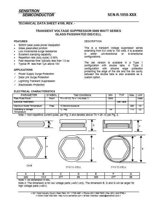
TECHNICAL DATA SHEET 4199, REV. -TRANSIENT VOLTAGE SUPPRESSOR 5000 WATT SERIESGLASS PASSIVATED DIE/CELLFEATURESDESCRIPTION • 5000W peak pulse power dissipation • Glass passivated junction• Low incremental surge resistance • Excellent clamping capability• Repetition rate (duty cycle): 0.05%• Fast response time: typically less than 1.0 ps • Typical IR less than 1µA above 10VAPPLICATIONSü Power Supply Surge Protection ü Data Link Surge Protectionü Lightning Transient Suppression ü Electrostatic ProtectionThis is a transient voltage suppressor series extending from 5.0 volts to 100 volts. It is available in either uni-directional or bi-directional configurations.The cell version is available in a Type 1 configuration with double tabs. A Type 2 configuration with silicone edge protection protecting the edge of the die and the die cavity between the double tabs is also available as a custom option.ELECTRICAL CHARACTERISTICSPARAMETERSYMBOLTest ConditionsMinTYPMaxUnitPeak Pulse Power Pppm TA = 25 8C, Tp = 1 ms (Note 1) 5000 Watts Electrical ParametersSee TableMaximum Solder Temperature Tmax 10 Second exposure 250 8C Operating & Storage TemperatureTj, Tstg-551758CNote 1: Non-repetitive current pulse, per Fig. 3 and derated above TA = 25 8C per Fig. 2.A B C D E F G 220 13.5 277 98 305 277 98 Note 1: All dimension in MILNote 2: The dimension is for low voltage parts (<40V) only. The dimension B, D and G will be larger for high voltage parts (>40V).CHIPTVS T1 CELL TVS T2 CELLTECHNICAL DATA SHEET 4199, REV. -Note 2: Die only configuration requires user to provide adequate energy absorption.SEN-R-1050-XXX 5000 Watt TVS SeriesPart NumberV r(V) Vz min@ Iz(V)Vz max@ Iz(V)Iz(mA)Vcc(V)Ip(A)Ir max@ V r(uA)SEN-R-1050-001 5.0 6.40 7.00 50 9.2 544.0 10000 SEN-R-1050-002 6.0 6.67 7.37 50 10.3 486.0 10000 SEN-R-1050-003 6.5 7.22 7.98 50 11.2 447.0 4000 SEN-R-1050-004 7.0 7.78 8.60 50 12.0 417.0 2000 SEN-R-1050-005 7.5 8.33 9.21 5 12.9 388.0 500 SEN-R-1050-006 8.0 8.89 9.83 5 13.6 368.0 300 SEN-R-1050-007 8.5 9.44 10.40 5 14.4 348.0 100 SEN-R-1050-008 9.0 10.00 11.10 5 15.4 325.0 40 SEN-R-1050-009 10.0 11.10 12.30 5 17.0 295.0 30 SEN-R-1050-010 11.0 12.20 13.50 5 18.2 275.0 10 SEN-R-1050-011 12.0 13.30 14.70 5 19.9 252.0 10 SEN-R-1050-012 13.0 14.40 15.90 5 21.5 233.0 10 SEN-R-1050-013 14.0 15.60 17.20 5 23.2 216.0 10 SEN-R-1050-014 15.0 16.70 18.50 5 24.4 205.0 10 SEN-R-1050-015 16.0 17.80 19.70 5 26.0 193.0 10 SEN-R-1050-016 17.0 18.90 20.90 5 27.6 181.0 10 SEN-R-1050-017 18.0 20.00 22.10 5 29.2 172.0 10 SEN-R-1050-018 20.0 22.20 24.50 5 32.4 154.0 10 SEN-R-1050-019 22.0 24.00 26.90 5 35.5 141.0 10 SEN-R-1050-020 24.0 26.70 29.50 5 38.9 129.0 10 SEN-R-1050-021 26.0 28.90 31.90 5 42.1 119.0 10 SEN-R-1050-022 28.0 31.10 34.40 5 45.4 110.0 10 SEN-R-1050-023 30.0 33.30 36.80 5 48.4 103.0 10 SEN-R-1050-024 33.0 36.70 40.60 5 53.3 93.9 10 SEN-R-1050-025 36.0 40.00 44.20 5 58.1 86.1 10 SEN-R-1050-026 40.0 44.40 49.10 5 64.5 77.6 10 SEN-R-1050-027 43.0 47.80 52.80 5 69.4 72.1 10 SEN-R-1050-028 45.0 50.00 55.30 5 72.7 68.8 10 SEN-R-1050-029 48.0 53.30 58.90 5 77.4 64.7 10 SEN-R-1050-030 51.0 56.70 62.70 5 82.4 60.7 10 SEN-R-1050-031 54.0 60.00 66.30 5 87.1 57.5 10 SEN-R-1050-032 58.0 64.40 71.20 5 93.6 53.5 10 SEN-R-1050-033 60.0 66.70 73.70 5 96.8 51.7 10 SEN-R-1050-034 64.0 71.10 78.60 5 103.0 48.6 10 SEN-R-1050-035 70.0 77.80 86.00 5 113.0 44.3 10 SEN-R-1050-036 75.0 83.30 92.10 5 121.0 41.4 10 SEN-R-1050-037 78.0 86.70 95.80 5 126.0 39.7 10 SEN-R-1050-038 85.0 94.40 104.00 5 137.0 36.5 10 SEN-R-1050-039 90.0 100.00 111.00 5 146.0 34.3 10 SEN-R-1050-040 100.0 110.00 123.00 5 162.0 30.9 10 SEN-R-1050-041 110.0 122.00 135.00 5 177.0 28.3 10 SEN-R-1050-042 120.0 133.00 147.00 5 193.0 26.0 10 SEN-R-1050-043 130.0 144.00 159.00 5 209.0 24.0 10 SEN-R-1050-044 150.0 167.00 185.00 5 243.0 20.6 10 SEN-R-1050-045 160.0 178.00 197.00 5 259.0 19.3 10 SEN-R-1050-046 170.0 189.00 209.00 5 275.0 18.2 10 SEN-R-1050-047 180.0 200.00 233.00 5 289.0 17.3 10TECHNICAL DATA SHEET 4199, REV. -10010001000010000011010010000.11101000.11.010.0100.01000.010000.0Fig. 1 - Peak Pulse Power Rating CurveP P P M -P e a k P u l s e P o w e r (k W )td - Pulse Width (sec.)0255075100255075100125150175200Fig.2 - Pulse Derating CurveTA - Ambient Temperature (°C)P P P M -P e a k P u l s e P o w e r (k W )0.01.02.03.04.0Fig.3 - Pulse Waveformt - Time(ms)I P P M - P e a kP u l s e C u r r e n t ,%Fig. 4 - Typical Junction CapacitanceC J , J u n c t i o n C a p a c i t a n c eVBR - Breakdown Voltage (V)02468255075100125150175200Fig. 5 - Steady State Power Derating CurveP P M (A V ),S t e a d y S t a t e P o w e rD i s s i p a t i o n (W )TL - Lead Temperature (°C)200250300350400450500110100Fig.6 - Maximum Non-repetitive ForwardSurge currentNumber of Cycles at 60 HZI F S M ,P e a k F o r w a r d S u r g e C u r r n e t (A )SENSITRONSEMICONDUCTORTECHNICAL DATADISCLAIMER:1- The information given herein, including the specifications and dimensions, is subject to change without prior notice to improve product characteristics. Before ordering, purchasers are advised to contact the Sensitron Semiconductor sales department for the latest version of the datasheet(s).2- In cases where extremely high reliability is required (such as use in nuclear power control, aerospace and aviation, traffic equipment, medical equipment, and safety equipment), safety should be ensured by using semiconductor devices that feature assured safety or by means of users’ fail-safe precautions or other arrangement.3- In no event shall Sensitron Semiconductor be liable for any damages that may result from an accident or any other cause during operation of the user’s units according to the datasheet(s). Sensitron Semiconductor assumes no responsibility for any intellectual property claims or any other problems that may result from applications of information, products or circuits described in the datasheets.4- In no event shall Sensitron Semiconductor be liable for any failure in a semiconductor device or any secondary damage resulting from use at a value exceeding the absolute maximum rating.5- No license is granted by the datasheet(s) under any patents or other rights of any third party or Sensitron Semiconductor.6- The datasheet(s) may not be reproduced or duplicated, in any form, in whole or part, without the expressed written permission of Sensitron Semiconductor.7- The products (technologies) described in the datasheet(s) are not to be provided to any party whose purpose in their application will hinder maintenance of international peace and safety nor are they to be applied to that purpose by their direct purchasers or any third party. When exporting these products (technologies), the necessary procedures are to be taken in accordance with related laws and regulations.。
恩智浦半导体 i.MX RT1050 数据手册说明书

恩智浦半导体数据手册:技术数据文件编号:IMXRT1050CEC第1.3版,2019年3月恩智浦保留根据需要更改生产规格细节的权利,以改进其产品设计。
MIMXRT1051DVL6AMIMXRT1051DVL6BMIMXRT1051DVJ6BMIMXRT1052DVL6AMIMXRT1052DVL6BMIMXRT1052DVJ6B适用于消费类产品的i.MXRT1050跨界处理器封装信息塑料封装196引脚MAPBGA,10 x 10 mm,0.65 mm间距196引脚MAPBGA,12 x 12 mm,0.8 mm间距订购信息参见第5页的表11 i.MX RT1050简介i.MX RT1050处理器属于全新的处理器系列,采用恩智浦先进的Arm®Cortex®-M7内核,运行速度高达600 MHz,可提供高CPU性能和实时响应。
i.MX RT1050处理器具有512 KB片内RAM,可灵活配置为TCM或通用片内RAM。
i.MX RT1050集成了先进的电源管理模块、DCDC和LDO,可降低外部电源的复杂性并简化上下电序列。
i.MXRT1050还提供各类存储器接口,包括SDRAM、RAW NAND、闪存、NOR闪存、SD/eMMC、四通道SPI;以及各类外设连接接口,包括WLAN、Bluetooth™、GPS、显示器和摄像头传感器。
i.MXRT1050还提供丰富的音频和视频功能,包括LCD显示器、基本2D图形、摄像头接口、SPDIF和I2S音频接口。
1. i.MX RT1050简介 (1)1.1. 特性 (2)1.2. 订购信息 (5)2. 架构概述 (8)2.1. 功能框图 (8)3. 模块列表 (9)3.1. 特殊信号考量 (15)3.2. 未使用模拟接口的推荐连接 (16)4. 电气特性 (18)4.1. 芯片级条件 (18)4.2. 系统电源和时钟 (25)4.3. I/O参数 (30)4.4. 系统模块 (36)4.5. 外部存储器接口 (41)4.6. 显示和图形 (51)4.7. 音频 (54)4.8. 模拟 (57)4.9. 通信接口 (64)4.10. 定时器 (77)5. 启动模式配置 (79)5.1. 启动模式配置引脚 (79)5.2. 启动设备接口分配 (79)6. 封装信息和触点分配 (84)6.1. 10 x 10 mm封装信息 (84)6.2. 12 x 12 mm封装信息 (96)7. 修订记录 (108)i.MX RT1050简介i.MX RT1050配备模拟接口,例如ADC、ACMP和TSC。
maxq1850 简要数据表说明书
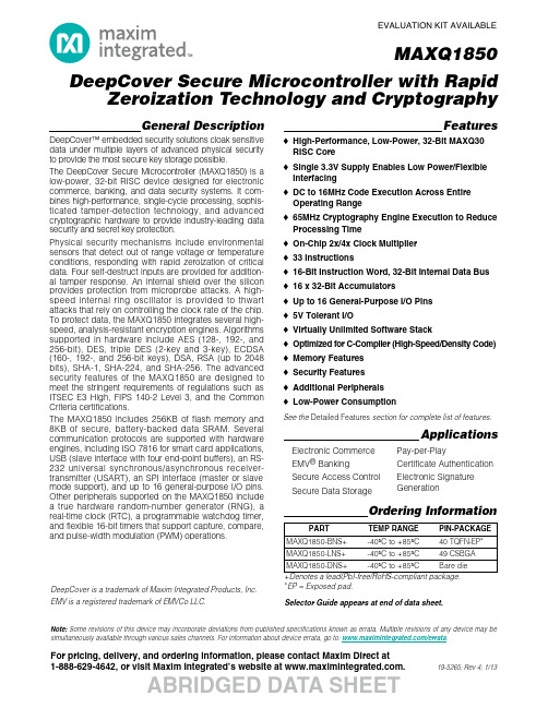
Note:Some revisions of this device may incorporate deviations from published specifications known as errata. Multiple revisions of any device may be simultaneously available through various sales channels. For information about device errata, go to: /errata .MAXQ1850For pricing, delivery, and ordering information, please contact Maxim Direct at 1-888-629-4642, or visit Maxim Integrated’s website at .EVALUATION KIT AVAILABLEDeepCover Secure Microcontroller with RapidZeroization Technology and CryptographyABRIDGED DATA SHEET19-5265; Rev 4; 1/13General DescriptionDeepCover™ embedded security solutions cloak sensitive data under multiple layers of advanced physical security to provide the most secure key storage possible.The DeepCover Secure Microcontroller (MAXQ1850) is a low-power, 32-bit RISC device designed for electronic commerce, banking, and data security systems. It com-bines high-performance, single-cycle processing, sophis-ticated tamper-detection technology, and advanced cryptographic hardware to provide industry-leading data security and secret key protection.Physical security mechanisms include environmental sensors that detect out of range voltage or temperature conditions, responding with rapid zeroization of critical data. Four self-destruct inputs are provided for addition-al tamper response. An internal shield over the silicon provides protection from microprobe attacks. A high-speed internal ring oscillator is provided to thwart attacks that rely on controlling the clock rate of the chip.To protect data, the MAXQ1850 integrates several high-speed, analysis-resistant encryption engines. Algorithms supported in hardware include AES (128-, 192-, and 256-bit), DES, triple DES (2-key and 3-key), ECDSA (160-, 192-, and 256-bit keys), DSA, RSA (up to 2048bits), SHA-1, SHA-224, and SHA-256. The advanced security features of the MAXQ1850 are designed to meet the stringent requirements of regulations such as ITSEC E3 High, FIPS 140-2 Level 3, and the Common Criteria certifications.The MAXQ1850includes 256KB of flash memory and 8KB of secure, battery-backed data SRAM. Several communication protocols are supported with hardware engines, including ISO 7816 for smart card applications,USB (slave interface with four end-point buffers), an RS-232 universal synchronous/asynchronous receiver-transmitter (USART), an SPI interface (master or slave mode support), and up to 16 general-purpose I/O pins.Other peripherals supported on the MAXQ1850 include a true hardware random-number generator (RNG), a real-time clock (RTC), a programmable watchdog timer,and flexible 16-bit timers that support capture, compare,and pulse-width modulation (PWM) operations.Features♦High-Performance, Low-Power, 32-Bit MAXQ30RISC Core ♦Single 3.3V Supply Enables Low Power/Flexible Interfacing ♦DC to 16MHz Code Execution Across Entire Operating Range ♦65MHz Cryptography Engine Execution to Reduce Processing Time ♦On-Chip 2x/4x Clock Multiplier ♦33 Instructions♦16-Bit Instruction Word, 32-Bit Internal Data Bus ♦16 x 32-Bit Accumulators♦Up to 16 General-Purpose I/O Pins ♦5V Tolerant I/O♦Virtually Unlimited Software Stack♦Optimized for C-Compiler (High-Speed/Density Code)♦Memory Features ♦Security Features ♦Additional Peripherals ♦Low-Power ConsumptionApplicationsOrdering InformationPART TEMP RANGE PIN-PACKAGE MAXQ1850-BNS+ -40°C to +85°C 40 TQFN-EP* MAXQ1850-LNS+ -40°C to +85°C 49 CSBGA MAXQ1850-DNS+ -40°C to +85°C Bare die+Denotes a lead(Pb)-free/RoHS-compliant package.*EP = Exposed pad.Selector Guide appears at end of data sheet.See the Detailed Features section for complete list of features.Electronic Commerce EMV ®Banking Secure Access Control Secure Data StoragePay-per-PlayCertificate Authentication Electronic Signature GenerationDeepCover is a trademark of Maxim Integrated Products, Inc.EMV is a registered trademark of EMVCo LLC.DeepCover Secure Microcontroller with Rapid Zeroization Technology and CryptographyMAXQ185012Maxim IntegratedABRIDGED DATA SHEETNote to readers: This document is an abridged version of the full data sheet. To request the full data sheet, go to /MAXQ1850and click on Request Full Data Sheet .CORE OSC ECDSARSA16KB ROM 8KB NV SRAMGPIOMAXQ30COREISO 7816SPIUSBUSART DSADES AES RNG TIMERSJTAG/DEBUG256KB FLASH CRYPTO OSC RTC PLL 32kHz12MHz MAXQ1850NOTE: THE BLOCK DIAGRAM SHOWS A TYPICAL SYSTEM CLOCK USED TO SUPPORT USB OPERATION AT 12MHz. MULTIPLE EXTERNAL CRYSTAL/CLOCK OPTIONS ARE AVAILABLE.Block DiagramDetailed Features♦High-Performance, Low-Power, 32-Bit MAXQ30RISC Core ♦Single 3.3V Supply Enables Low Power/Flexible Interfacing ♦DC to 16MHz Code Execution Across Entire Operating Range ♦65MHz Cryptography Engine Execution to Reduce Processing Time ♦On-Chip 2x/4x Clock Multiplier ♦33 Instructions♦Three Independent Data Pointers Accelerate Data Movement with Automatic Increment/Decrement ♦16-Bit Instruction Word, 32-Bit Internal Data Bus ♦16 x 32-Bit Accumulators♦Up to 16 General-Purpose I/O Pins ♦5V Tolerant I/O♦Virtually Unlimited Software Stack♦Optimized for C-Compiler (High-Speed/Density Code)♦Memory Features256KB Flash, Composed of 2048 Byte Sectors (1K Erase/Write Cycles per Sector)8KB Battery-Backed Data SRAMDedicated Cryptographic Memory Space♦Security FeaturesUnique IDTamper Detection with Rapid Key/Data Destruction Four Self-Destruct InputsHardware AES and DES EnginesPublic Key Cryptographic Accelerator for DSA,ECDSA, and RSASupports SHA-1, SHA-224, and SHA-256Real Hardware RNG and PRNG Hardware CRC-32/16Unalterable, Battery-Backed Real-Time Clock ♦Additional PeripheralsPower-Fail WarningPower-On Reset/Brownout ResetJTAG I/F for System Programming and Accessing On-Chip Debugger USB I/F with Four End-Point Buffers ISO 7816 Smart Card UART with FIFOFour 16-Bit Timer/Counters, Two with PWM FunctionSPI and USART Communication Ports Programmable Watchdog Timer ♦Low-Power Consumption150nA Typical Current Draw in Battery-Backed Mode,Preserving 8KB NV SRAM and with Security Sensors Active (460nA with RTC Active)。
NXP半导体 i.MXRT1050产品使用寿命估算说明书
NXP半导体文档编号:AN12170应用笔记Rev.0,2018年4月i.MXRT1050产品使用寿命估算原文链接:https:///docs/en/application-note/AN12170.pdf1.引言本文档根据认证过程中使用的标准介绍了i.MXRT1050应用处理器产品的使用寿命估算方法。
这里描述的产品使用寿命是估算的,并不代表处理器产品的实际保证使用寿命。
i.MX RT系列有许多处理器产品,它们支持高性能的运算处理和多媒体能力,并提供不同的认证资质等级。
不同认证资质等级的i.MX RT1050产品有着不同的最大目标运行频率和最高支持结温。
本文为您提供了目标运行频率和支持结温如何影响不同认证资质等级的i.MX RT1050产品使用寿命的解释指导。
内容1.引言 (1)2.设备认证资质等级及可用开机时间 (3)2.1.商业等级资质 (3)2.2.工业等级资质 (4)3.结合用例 (6)©2018NXP B.V.引言i.MXRT1050产品使用寿命估计,应用说明,Rev.0,04/20182NXP半导体每个支持的认证资质级别(商业级和工业级)定义了处理器在给定的一组工作条件下若干可用的开机时间(PoH)。
工作条件如:•应用(商业级和工业级)的目标频率—目标频率由处理器内核架构的输入电压(VDD_SOC_IN)决定。
—使用片上DCDC供电或片上DCDC旁路模式。
–当使用DCDC旁路模式时,目标电压不应设置为数据手册中指定的最小值。
所有电源管理IC都有允许的公差,因此目标电压必须设置为高于最小指定电压,以考虑PMIC的公差。
本文计算中假定的公差为+25mV。
–片上DCDC供电模式使用片上DCDC模块为i.MX RT系列产品的内核逻辑提供电源。
该DCDC模块具有良好的特性,可以输出精确的最小指定电压。
使用片上DCDC供电模式,可以实现更长的开机时间。
•运行时间与待机时间的百分比—运行状态意味着处理器正处于有效运行模式。
Giga-tronics GT-1050B微波功放器技术数据表说明书

Technical DatasheetGT-1050B Microwave Power Amplifier 2 GHz to 50 GHzBroadband High-Power Instrumentation Amplifier35527 -Rev.A / US13071135527-R e v . A / U S 130711The Giga-tronics GT-1050B Microwave Power Amplifier incorporates broadband MMIC-based architecture.These state-of-the-art amplifiers are based on solid-state parallel MMIC design with exceptionally widebandwidth and high power. The unique circuit topology is highly reliable, with performance that excels where extremes of bandwidth and power are demanded.The Giga-tronics GT-1050B Microwave Power Amplifiers provide excellent pulse fidelity, low intermodulation distortion, high linearity and superior gain flatness without the warm-up time, drift or aging issues of traveling wave tube amplifiers (TWTA). They feature low noise figure, low harmonics and spurious content, and are highly tolerant to load mismatch.1• 2 GHz to 50 GHz eliminates band switching, reduces cost and complexity • Solid-state technology for low noise, high reliability and long life•Ideal for R&D Lab, ATE Systems, Wireless Communications and Defense EW applicationsGT-1050B Microwave Power Amplifier35527-R e v . A / U S 130711The Giga-tronics GT-1050B Microwave Power Amplifier offers linear high-power amplification across multi-octave bands. Theyis ideal for testing in R&D Lab, ATE Systems, wireless communications applications and Defense EW systems. The 2 GHz to 50 GHz frequency range allows broadband testing without band switching or swapping narrow band amplifiers resulting in faster and more accurate testing.The amplifiers can be used in wireless communications and component testing wherever a highly linear amplifier is needed. These microwave power amplifiers with excellent pulse fidelity are ideal for many Aerospace and Defense applications, including EW, ECM, ECCM, radar and satellite system signal simulation and testing. The GT-1050B is an ideal ATE system building block for boosting test signals to overcome cable and connector loss whenever long cable runs are needed in assembly bays, environmental test chambers or field locations.The amplifier nominally provides 25 dB of gain over the 2 GHz to 50 GHz frequency range. The GT-1050B can be paired with a Giga-tronics 2540B 40 GHz Microwave Signal Generator or with Giga-tronics 2550B 50 GHz Microwave Signal Generator, increasing the overall output power while preserving the synthesizer’s fast switching speed, modulation, and high signal fidelity.2GT-1050B Microwave Power Amplifier35527-R e v . A / U S 130711Frequency RangeGT-1050B2 GHz to 50 GHzOutput PowerOutput power is specified as minimum saturated power into 50 Ohm load with +5 dBm input, at 23°C ± 5°C Input power for normal operation should be limited to +20 dBm maximum.Range Specifications2 to 10 GHz +30 dBm (1 Watts) nominal, +26 dBm (400 mW) minimum 10 to 30 GHz +28 dBm (600 mW) nominal, +25 dBm (300 mW) minimum 30 to 40 GHz +27 dBm (500 mW) nominal, +23 dBm (200 mW) minimum 40 to 50 GHz+24 dBm (250 mW) nominal, +20 dBm (100 mW) minimumGain FlatnessNominal gain is 25 dB, minimum gain > 20 dB.Gain flatness is specified as maximum variation with -5 dBm input and 50 Ohm load.Range Specifications 2 to 40 GHz ± 2.5 dB nominal 2 to 50 GHz± 3.5 dB nominal3GT-1050B Microwave Power Amplifier35527-R e v . A / U S 1307114Input and Output VSWR2 to 30 GHz30 to 40 GHz 40 to 50 GHz Input, 50 ohms 1.5:1 nominal 2.0:1 nominal 2.3:1 nominal Output, 50 ohms2.0:1 nominal2.3:1 nominal2.9:1 nominalAdditional SpecificationsParameter Specifications StabilityUnconditionally Stable Maximum Load VSWR 3:1Maximum Input Power +20 dBm Third Order Intercept +37 dBm nominal Harmonic Distortion*< -30 dBc nominal Spurious*< -60 dBc nominal Reverse Isolation > 50 dBNoise Figure< 10 dB nominal, < 14 dB maximum* Note: Harmonics measured at +10 dBm output power. Spurious measured at -5 dBm input power levelGeneral SpecificationsLine Voltage 100 to 240 VAC, 47 to 63 Hz, Single Phase Line Power20 VA maximum Operating Temperature 0°C to +50°C Storage Temperature -20°C to +75°CDimensions 2.5” H x 6.8” D x 7.0” W (64 mm H x 173 mm D x 178 mm W) Weight 4.5 lbs (2 kg)RF ConnectorsInput: 2.4 mm compatible 1.85 mm (f) V connectorOutput: 2.4 mm compatible 1.85 mm (f) V connectorGT-1050B Microwave Power Amplifier35527-R e v . A / U S 130711Ordering InformationGiga-tronics has a network of RF and Microwave instrumentation sales engineers and a staff of factory support personnel to help you find the best, most economical instrument for your specific applications. In addition to helping you select the best instrument for your needs, our staff can provide quotations, assist you in placing orders, and do everything necessary to ensure that your business transactions with Giga-tronics are handled efficiently.Model NumberFrequency RangeGT-1050BMicrowave Power Amplifier, 2 GHz to 50 GHzAvailable Options and Accessories Option Description46Add Rack Mount KitGiga-tronics Support ServicesAt Giga-tronics, we understand the challenges you face. Our support services begin from the moment you call us. We help you achieve both top-line growth and bottom-line efficiencies by working to identify your precise needs and implement smart and result orientated solutions. We believe and commit ourselves in providing you with more than our superior test solutions. For technical support, contact:Tel: 1-800-726-GIGA (4442) or (925) 328-4669Email:***********************UpdatesAll data is subject to change without notice. For the latest information on Giga-tronics products and applications, please visit out website:535527-R e v . A / U S 130711©2013 Giga-tronics Incorporated. All Rights Reserved. All trademarks are the property of their respective owners.。
YL-1050A电子电路焊接与智能检测系统模块

YL-1050A电子电路焊接与智能检测系统模块简介YL-1050A电子电路焊接与智能检测系统模块是目前市场上较为成熟的一款集焊接与测试功能于一体的模块。
该模块可以实现对电子电路的焊接、联通测试、短路测试、接地测试和板间距等测试,具有快速、准确和高效的特点,广泛应用于电子制造、航空航天、自动化控制等领域。
焊接功能该模块在焊接方面采用高精度烙铁,可在芯片引脚精细焊接,保证焊接质量的同时避免损伤芯片。
同时,系统采用全自动化焊接方式,能够有效减少人工干扰,加快焊接速度,提高效率。
测试功能在测试方面,YL-1050A模块可实现对电路板的联通测试、短路测试、接地测试和板间距等测试。
系统在测试环节采用智能算法,自动判断测试结果,杜绝人为误差,并及时记录测试数据,为生产质量追溯提供有力支持。
技术参数1.焊接功率:60W2.焊接温度:200°C-480°C3.焊接头寿命:长达100000次4.联通测试:支持20组测试数据,测试速度≤2s/组5.短路测试:支持百分百检测6.接地测试:支持百分百检测7.板间距测试:0.05mm-5.00mm8.测试精度:0.01mm应用场景YL-1050A模块适用于各类电子制造场景,如手机、电脑、芯片等的生产制造过程中的电路焊接和检测。
同时,在其他领域,如航空航天、自动化控制等领域也有广泛的应用。
优势1.高效:系统采用自动化焊接和智能算法,不仅保证了焊接质量,也提高了整体的生产效率。
2.准确:系统针对不同的测试项目,设计了不同的测试模块,在测试环节中能够自动化判断测试结果,提高了测试的准确度。
3.稳定:高精度烙铁和智能算法,让整个系统在长时间工作中仍然保持了稳定性和可靠性。
4.易操作:整个系统操作简单、易学易用,可减少人为干扰,提高生产效率和产出质量。
总结YL-1050A电子电路焊接与智能检测系统模块是当前市场上较为成熟的电子制造设备,其应用范围广泛,操作简单,可通过自动化焊接和智能测试算法,保证生产效率和产出质量,便于各行各业的生产制造和技术人员使用。
- 1、下载文档前请自行甄别文档内容的完整性,平台不提供额外的编辑、内容补充、找答案等附加服务。
- 2、"仅部分预览"的文档,不可在线预览部分如存在完整性等问题,可反馈申请退款(可完整预览的文档不适用该条件!)。
- 3、如文档侵犯您的权益,请联系客服反馈,我们会尽快为您处理(人工客服工作时间:9:00-18:30)。
19-5822; Rev 1; 7/11
EVALUATION KIT AVAILABLE
MAXQ1050 Secure USB Microcontroller with Asymmetric Cryptography
General Description
The MAXQ1050 is a low-power secure microcontroller designed for USB secure token and smart card reader applications that require certificate-based or other public key cryptographic schemes. The device also incorporates a sophisticated security mechanism to protect secret key data; two self-destruct inputs and environmental monitors (temperature and voltage sensors) erase secret key data when an attack condition is detected. The device has an integrated full-speed USB device interface (including transceiver), hardware SPI™ controller, and an ISO 7816 UART (universal asynchronous receiver-transmitter) for smart card communication. The device supports highspeed encryption with hardware accelerators for AES, RSA, DSA, ECDSA, SHA-1, SHA-224, SHA-256, DES, and 3DES. A true hardware random-number generator is included for key generation and challenge generation. The device uses the 32-bit, pipelined, highly efficient MAXQ30 microcontroller core. It integrates 128KB flash memory, 12KB of volatile SRAM, 4KB of battery-backed erasable NV SRAM, and 256B of battery-backed, secure zeroization NV SRAM. An additional 1.5KB of volatile cryptographic memory can also be used as general-purpose data memory. The 256B of battery-backed NV SRAM can be used for key storage and other critical data. The 256B memory can be erased in less than 1Fs using a single pulse (“rapid zeroization”), even in battery-backed mode. The device is powered either from the USB bus or by a separate 3.3V voltage supply. A battery connection is provided for applications that want to maintain secret key data for years without draining the battery from application use. In battery-backed mode, the NV SRAM and security sensors consume less than 240nA (typ). Battery backup is optional; applications can choose to store critical data in the flash memory when the cost of the battery outweighs the benefits of constant monitoring for tamper conditions.
POWER-ON RESET/POWER-FAIL WARNING WATCHDOG TIMER 20MHz INTERNAL OSCILLATOR INTERNAL 65MHz CRYPTO OSCILLATOR
HARDWARE MULTIPLIER 4 x 16-BIT TIMER USB WITH INTEGRATED TRANSCEIVER ISO 7816 UART GPIO
128KB FLASH WITH CODE SCRAMBLING
SHA
MAXQ30 CORE
JTAG/DEBUG USART
12KB VOLATILE SRAM
����������������������������������������������������������������� Maxim Integrated Products 1
For pricing, delivery, and ordering information, please contact Maxim Direct at 1-888-629-4642, or visit Maxim’s website at .
Applications
Security and Banking Tokens Certificate Management Electronic Signature Generation Smart Grid Security Prepaid Utility e-Commerce Secure Access Control Pay-per-Play
ABRIDGED DATA SHEET
MAXQ1050 Secure USB Microcontroller with Asymmetric Cryptography
Block Diagram
UTILITY ROM
RANDOM-NUMBER GENERATOR MAA 3DES
ECDSA DSA RSA AES
Ordering Information appears at end of data sheet. SPI is a trademark of Motorola, Inc.ห้องสมุดไป่ตู้
For related parts and recommended products to use with this part, refer to: /MAXQ1050.related Note: Some revisions of this device may incorporate deviations from published specifications known as errata. Multiple revisions of any device may be simultaneously available through various sales channels. For information about device errata, go to: /errata.
Features
S High-Performance, Low-Power, 32-Bit MAXQ30 RISC Core S Operates from USB Power or Single 3.3V Supply S Runs from 20MHz (typ) Internal Oscillator S Supports External 12/24MHz Crystal Oscillator for Microcontroller and USB Operation S On-Chip 2x/4x Clock Multiplier S 16-Bit Instruction Word, 32-Bit Internal Data Bus S 16 x 32-Bit Accumulators S 16 x 32-Bit General-Purpose Working Registers S Up to 20 General-Purpose I/O Pins S 5V Tolerant I/O S Virtually Unlimited Software Stack S Optimized for C-Compiler (High-Speed/Density Code) S Memory 128KB Flash Memory, 512 x 32 Page Size Flash Memory Supports 20k Erase/Write Cycles per Sector 256B of Secure NV SRAM 4KB Battery-Backed NV SRAM 12KB SRAM Secure JTAG/TAP for In-System Programming S Security Unique 64-Bit Serial Number Tamper Detection with Rapid Key/Data Destruction Secret Key Destruction on Tamper Events Permanent Loader Lockout Option Proprietary Code Scrambling Technique Using Random Keys Hardware Accelerators for AES, RSA, DSA, ECDSA, DES, 3DES, SHA-1, SHA-224, SHA-256 True Hardware Random-Number Generator Temperature and Voltage Sensors to Detect Attacks Two Self-Destruct Input Pins S Additional Peripherals Power-Fail Warning Power-On-Reset/Brownout Reset JTAG I/F for System Programming and Accessing On-Chip Debugger Full-Speed USB Device with Six Endpoint Buffers and Integrated Transceiver ISO 7816 Smart Card UART with FIFO 16-Bit Programmable Timers/Counters with Prescaler, Capture/Compare, and PWM SPI Master/Slave Hardware Programmable Watchdog Timer Up to 20 General-Purpose I/O Pins with Eight External Interrupts
