地球仪中文说明书
Google Earth 使用手册说明书

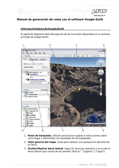
Manual de generación de rutas con el software Google Earth Informaciónbásica deGoogle EarthEl siguiente diagrama describe algunas de las funciones disponibles en la ventana principal de Google Earth:1.Panel de búsqueda:utilícelo para buscar lugares e instrucciones sobrecómo llegar y administrar los resultados de las búsquedas.2.Vista general del mapa:úsela para obtener una perspectiva adicional dela Tierra.3.Ocultar/Mostrar barra lateral:haga clic para que aparezca o se oculte labarra lateral(que consta de los paneles"Buscar","Lugares"y"Capas").4.Marca de posición:haga clic para añadir una marca de posición en unaubicación.5.Polígono:haga clic para añadir un polígono.6.Ruta:haga clic para añadir una ruta(una o varias líneas).7.Superposición de imágenes:haga clic para añadir una superposición deimagen sobre la Tierra.8.Medir:haga clic para medir una distancia o un tamaño deárea.9.Sol:haga clic para aplicar luz solar al paisaje.10.Cambiar al Cielo:haga clic para ver las estrellas,las constelaciones,lasgalaxias,los planetas y la luna de la Tierra.11.Correo electrónico:haga clic para enviar un mensaje de correoelectrónico con una vista o imagen.12.Imprimir:haga clic para imprimir la vista actual de la Tierra.13.Ver en Google Maps:haga clic para mostrar la vista actual en GoogleMaps,en el navegador web.14.Controles de navegación:utilícelos para inclinar,acercarte,alejarte,mirar y moverte alrededor de donde te encuentres(ver a continuación).15.Panel"Capas":utilícelo para mostrar los lugares de interés.16.Panel"Lugares":utilícelo para localizar,guardar,organizar y volver avisitar las marcas de posición.17.Añadir contenido:haga clic aquípara importar contenido de interésdesde la Galería KML.18.Visor3D:podráver el planeta y su relieve en esta ventana.19.Barra de estado:en ella se ven las coordenadas,la elevación,la fecha delas imágenes y su estado de streaming.Uso del ratónPara empezar a navegar con el ratón,basta con colocar el cursor en medio del visor(la imagen de la Tierra),hacer clic en uno de los botones(el derecho o el izquierdo),mover el ratón y fijarse en quéocurre en el visor.Según el botón del ratón que haya pulsado,el cursor cambiaráde forma para indicar que su comportamiento serádistinto.Moviendo el ratón mientras se pulsa uno de los botones se puede:arrastrar la vista en cualquier dirección,acercar o alejar la imagen,inclinar la vista(tendráque usar el botón central o la rueda dedesplazamiento),mirar alrededor desde unúnico punto de mira,girar la vista(tendráque usar el botón central o la rueda de desplazamiento).En la siguiente tabla se describen todas las acciones que puedes llevar a cabo moviendo el ratón.Uso de los controles de navegaciónPara ver y usar los controles de navegación,mueva el cursor sobre la esquina derecha del visor3D.Al iniciar Google Earth y mover el cursor sobre estaárea,los controles de navegación se van desvaneciendo cuando mueva el cursor a cualquier otro lugar.Para ver estos controles de nuevo,basta con mover el cursor sobre la esquina derecha del visor3D.Los controles de navegación de Google Earth ofrecen el mismo tipo de acciones de navegación que se pueden obtener con el ratón.Además,puede usar los controles para acercar o alejar la imagen y desplazarse(a lo mejor para ver una perspectiva o un relieve),asícomo girar la vista.En el siguiente diagrama se muestran los controles y se explican sus funciones.Dibujo de rutas y polígonosPuede dibujar rutas y polígonos sin forma definida en el visor y guardarlos en la carpeta Mis lugares igual que cualquier marca de posiciós rutas y los polígonos comparten todas las funciones de los datos de marcas de posición, incluido el nombre,la descripción,el estilo de vista y la ubicación.Siga estos pasos para dibujar una ruta.1.Coloque el visor de forma que se muestre la región que desea marcar.Cuanto más detallada sea la vista,con más precisión podráseguir los accidentes del relieve con su dibujo.En el menú"Añadir", seleccione Ruta(Ctrl+Mayús+T).Se abriráel cuadro de diálogo"Nueva ruta"o"Nuevo polígono"y el cursor cambiaráa una herramienta cuadrada de dibujo.Introduzca las propiedades(Nombre)de su dibujo igual que haría con cualquier otro tipo de dato de lugar.2.Consejo:cambie el color de estilo(ficha"Estilo,color")de la línea o del polígono en lugar de usar el color blanco predeterminado.De ese modo,se distinguirámejor la forma que va a dibujar.Haga clic en el visor para empezar su dibujo y utilice los siguientes métodos para conseguir la forma que desea:o Forma indeterminada:haga clic una vez,mantén pulsado elbotón del ratón y arrástrelo.El cursor cambiaráa una flecha haciaarriba para indicar que estáutilizando el modo de forma libre.Amedida que arrastre el cursor por el visor,la forma irásiguiendola ruta que marque.Si estádibujando una ruta,apareceráunalínea,y si estádibujando un polígono,una forma rodearála rutadel cursor,conectando siempre los puntos de inicio y final.o Forma regular:haga clic y suelte el botón.Mueva el ratón hastael nuevo punto y haga clic para añadir puntos adicionales.Eneste modo,el cursor no deja de ser una herramienta cuadrada dedibujo.Puede utilizar una combinación de estos modos de dibujo paracombinar bordes irregulares con bordes rectos.Para pasar del modode forma irregular al modo de forma geométrica,basta con soltar elbotón del ratón,colocar el puntero en un lugar distinto y hacer clic.Se dibujaráuna línea recta entre elúltimo punto y el más reciente.Invierte el proceso para entrar de nuevo en el modo de dibujo deforma irregular.Una vez terminada la generación de la ruta deseada con un doble clik del botón derecho del mouse,usted puede guardar en su computadora el resultado.Una vez cerrada la ventana de propiedades de la ruta creada,éstaúltima aparece en la barra lateral,dentro del apartado Mis Lugares,como un item mas de los que tenemos desplegados.Haga click con el botón derecho del mouse sobre el nombre dado a la ruta,apareceráun menúde opciones,del cual deberáelegir guardarcomo…En la pantalla de opciones de guardado,elegir laopción Kml(*.Kml),poner un nombre,y click sobre elbotón aceptar.Ya guardado en su disco rígido,el archivo Kml generado puedeser enviado por mail,o algúnotro medio disponible para su posterior ingreso en el sistema.。
GPS12翻译版说明书要点

GPS12使用手册首先感谢您选择了GARMIN GPS12,这是一款使用简单,携带方便的GPS导航仪。
其致力于长时间提供优质的导航服务和良好的人机互动。
为了更好地使用本产品,请仔细阅读使用说明书!为了方便理解,本说明书分为四个部分:简介部分:对操作手册一些专业术语简要概述;入门部分:介绍了本产品的基本特征,简述了利用GPS12快速定位的方法;参考部分:说明了GPS12的先进功能及操作细节;附录部分:包含初始化说明和其他多个操作,如地图基准,时间偏移,索引。
在开始使用GARMIN GPS12之前,请仔细检查以下的几个地方:如有缺失任何部件,请立即与经销商联络。
标准配件:GARMIN GPS12;使用说明书;腕带;快速使用手册。
经销商应提供的配件有:GARMIN GPS12包;旋转接头;外接天线;电源/数据线。
我们希望本产品能尽可能满足您的导航需求,我们将尽我们最大的努力让其成为一款优秀的户外设备。
IGPS系统是美国开发的一套系统,其负责该系统的维护与准确性。
该系统如有变化将会影响所有GPS设备的准确性及使用性能。
虽然GPS12是一种精密电子导航系统(导航设施),但是如果误操作或者误解其用途,那么该系统将不再安全。
个人使用GPS12一些要求:为了减少不安全操作的风险,应仔细阅读和理解本操作手册的各方面并利用模拟系统进行操作练习。
在实际使用时,应结合其他导航设备包括从其他助航设备,目视瞄准,地图等信息仔细比较GPS12的信息显示。
出于安全考虑,须在继续航行之前解决任何误差。
注意:此装置符合FCC的第15部分对家庭或办公室使用的B类数字设备的限额要求。
它已经过测试,符合所有必要的FCC标准(FCC:全称美国联邦通讯委员会Federal Communications Commission)。
本产品通过无线电进行通信,如不按其操作规程使用,则会对信号的准确性有很大的影响。
当然,在按照规则合理使用设备时,也不能排除其他设备对本产品的干扰,当遇到干扰时,可以通过重启来恢复使用,当然,远离干扰源或连接该设备到其他的系统也是避免干扰的有效措施。
地球仪课件粤人版地理七年级上册(3)

地球仪在教育领域的应用和发展前景
• 地球仪在教育领域的应用:
• * 辅助地理教学:帮助学生了解地球的形状、大小、自转和公转等基本概念。
• * 探索世界文化:通过地球仪上的不同国家和地区的标识,学生可以了解不同文化的特点和历史 背景。
• * 培养空间思维:地球仪的使用可以帮助学生培养空间思维和想象力,更好地理解地理现象和问 题。
• 地球仪的发展前景:
• * 智能化发展:随着科技的不断进步,未来地球仪将更加智能化,具备更多交互功能和多媒体展 示方式。
• * 个性化定制:满足不同年龄段、不同学习需求的学生,提供更加个性化的学习体验。
• * 多元化应用:除了辅助地理教学外,地球仪还可以应用于历史、政治、经济等多个学科领域, 为教育提供更加全面的支持。
中国的经济发展和文化传承
中国的经济发展:介绍中国近年来的经济发展情况,包括GDP增长、产业结构调整、对外 贸易等方面的内容。
中国的文化传承:介绍中国传统文化的发展历程和主要特点,包括儒家文化、道家文化、 佛教文化等方面的内容。
中国的地理优势:介绍中国地理位置的优势,包括海岸线长、内陆广阔、多山多水等方面 的内容。
地球仪的正确使用姿势
手持地球仪,调整底座和轴的位置,确保地球仪平稳放置 转动地球仪时,应该用双手轻轻转动,避免用力过猛导致地球仪倾斜或翻倒 在观察地球仪时,应该将眼睛贴近地球仪表面,避免距离过远导致视线模糊 在使用地球仪时,应该注意保护地球仪表面,避免刮花或损坏
地球仪的正确操作步骤
打开电源:确保地球仪连接 电源,并打开电源开关。
地球的四季变化
地球公转与自 转:地球公转 是四季变化的 主要原因,自 转则影响昼夜
交替。
四季划分:春 季、夏季、秋 季和冬季,每 个季节都有其 特定的气候和
《地球仪》 PPT实用课件

《地球仪》 PPT实用课件
•
8.从人的实践活动看,“万物并育而 不相害 ”则涉 及不同 的个体 、团体 、民族 、国家 之间的 共处、 交往问 题,它 以承认 不同个 体的差 异、不 同社会 领域的 分化为 前提。 个体的 差异、 不同社 会领域 的分化 是一种 历史演 化过程 中无法 否认的 事实, 如何使 分化过 程中形 成的不 同个体 、存在 形态以 非冲突 的方式 共处于 世界之 中,便 成为“ 万物并 育而不 相害” 所指向 的实质 问题.
各种不同的地球仪
对照地球仪,把四大洋和七大洲的名称填写在下图中
北冰洋
北美洲
欧洲
亚洲
太平洋
南美洲 大西洋
非洲
印度洋Leabharlann 太平洋 大洋洲南极洲地轴
北极
自西向 东转动
南极
赤道和纬线
请说出纬线的特点: 1、纬线的形状 圆形 2、纬线是否等长
不等长,越接近赤道越长
3、纬线所指示的方向
东西方向
经线
•
6强调“道”和“人”之间不可分割、 相互联 系的重 要涵义 之一, 是肯定 道所具 有的各 种意义 唯有通 过人自 身的知 和行、 认识世 界和改 变世界 的过程 ,才能 呈现出 来。正 如深山 中的花 自开自 落,并 无美或 不美的 问题, 只有在 人的审 美活动 中,它 的审美 意义才 得到呈 现。
请说出经线的特点: 1、经线的形状 半圆形 2、经线是否等长 等长 3、经线所指示的方向 南北
东西 无数
总结
• 地轴、经线、纬线都不是实际存在的。它们是为了 更加方便的研究地球而假象出来的。
• 地球是存在一定的角度而倾斜着。
《地球仪》 PPT实用课件
麦哲伦的航线
五年级上册科学3.4《地球仪》

20° 25°
25° 20° 15° 10° 5°
·C
C:25°S, 25°W
30°
35°
40°
·
45°
2、C 在D的东_D_北___方向
D:40°S, 15°W
B:北纬40° ,东经45°
(2)A位于B的
A
__西__南__方向
50° 45 ° 40° 35° 30 ° 25° 20°
0°
1.写出A、B、C、D四地的经度和纬度
A:南纬30 °,西经120° B:北纬30 °,东经120° C:北纬30 °,西经120° D:南纬30 °,东经120°
东西半球的划分:
高纬度: 60°N---90°N 60°S---90°S
五条特殊纬线
1.北京的纬度为北纬40°,经度为东经116°, 则它是位于___(填“东东”或“西” )半球和 ___(北填“南”或“北” )半球
2.悉尼的纬度为南纬34°,经度为东经151°,则 它是位于___东(填“东”或“西” )半球和南___ (填“南”或“北” )半球 3.巴西利亚的纬度为南纬16.5°,经度为西经 48.5°,则它是位于__西_ (填“东”或“西”) 半球和南___ (填“南”或“北” )半球
4、指出下列图中A、B两地所在的经度和纬
度30° 15° 0° 15° 30° 45°
A:北纬10°,
·A
10°
西经30°
·B
0°
10° B:南纬10°,
20°
东经15°
5、指出A、B两地所处的半球
A:北半球,西半球。 B:南半球,东半球。
一、地球的模型——地球仪
1、地轴: 地球自转轴 2、北极: 地轴指向北极星附近的一端
伟易达 视听百科地球仪 用户手册说明书

3
产品特征:
1. 开/关机
长按开/关机键几秒钟开机,你将听到欢迎语。
若通过以上步骤仍不能排除故障,敬请联系就近 的伟易达®特约维修点。伟易达®特约维修点详见保修 卡。
如果仍存在问题,请拨打我们的客服电话: 400-188-8628。我们的客服人员将竭诚为您服务。
版权声明:
vtech® ,伟易达®均属伟易达集团注册商标。未经 授权,不得使用。
6
Vtech AR地球仪APP
维护与保养:
1. 用柔软的干布擦拭主机表面,保持机身清洁。 2. 避免阳光直射,远离任何热源。 3. 当长期不用时,请将电池取出。 4. 不可与硬物相碰撞,或试图拆卸主机。 5. 地球仪应存放在干燥的区域,避免受潮,不可把
地球仪浸在水中。 6. 定期检查电源适配器、USB连接线、外壳和其他部
件是否损坏,发现损坏时应停止使用,直至修复 完好。
6.2 本公司承担维修产品返回所产生的快递费(只 限于在保修期之内的产品),您寄出所产生的快 递费,误工费等其它任何其它费用本公司均不予 承担。
七.一般条款:
7.1 如本条款被法律机关裁定为部分或全部无效,不 影响其他部分的效力,本条款其他内容在未被裁 定为无效的范围内仍然具有完全的效力。
7.2 本保修条款最终解释权归伟易达电子实业(深 圳)有限公司所有。
安卓系统最低配置 Android 5.0+ OpenGLES2.0
1G RAM, 800M储存空间
1.1地球仪(第二课时)课件(33张PPT) 粤人版地理七年级上册

请为下列纬线标注南北纬,并判断南北半球。
A 10° N
0° B
10° S
30° N C
20° N
10° N
50° S D
60° S
70° S
A 10°N(北半球) B 10°S(南半球) C 20°N(北半球) D 60°S(南半球)
纬线和纬度的判读
高、中、低纬度的划分
高纬度:
南北纬 60°~ 90°
B A.以180°经线为界,东经和西经的度数分别向东、向西愈来愈大
B.以0°经线为界,东经和西经的度数分别向东、向西愈来愈大
C.以赤道为界,北纬和南纬的度数分别向北、向南愈来愈小
D.以赤道为界,北纬和南纬的度数分别向北、向南愈来愈小,到北极点和南极点为0°
A 3.0°纬线又叫( )
A.赤道
B.北回归线
20°W 0° 20°E B
东半球
70°W 60°W 50°W
C
东半球
160°E 170°E 180°E 170°W
D
西半球
西半球 经线和经度的判读
相邻两条经线,在极点距 离最近(相交),在赤道 距离最远。
所有的经线均为半圆形,故在地球仪是
两条相对的经线组成一个经线圈。
构成经线圈的两条经线经度之和180°,东 西经符号相反。
C.本初子午线
D.北极点
1.东西半球分界线在( C )
A.20°E,160°W
B.0°
C.20°W,160°E
D.180°
2.我国首都北京的经纬度约是(40°N,116°E),可以判断北京位
于( B )
①东半球 ②西半球 ③北半球 ④南半球
A.②③
B.①③ C.②④
粤人版初中地理七上 第一章 第2节 《地球仪 》优质课件 (共45张PPT)

第二课时
复习上节课
• 用画图的方法复习地球仪的知识
相对的两根经线组成一个经线圈。 如:0°经线和180°经线组成一个经线圈。
经线
在地球仪上,能绘出无数条经线和纬线,人们为 了区别不同的经线,而给经线标定的度数叫经度,为 了区别不同的纬线而给纬线标定的度数叫纬度。
经度(西经和东经) 如:东经160
度,西经20度 可写为…
重要的经线
本初子午线 东经、西经的起点
180°经线
英国首都伦敦东南的格林尼治天文台旧址有一座子 午宫,那里有一条宽10多厘米的铜制子午线地面标志镶
嵌在大理石地面上,笔直地从宫中伸出,这就是闻名世
界的“本初子午线”。国际科学界把它确定为计算地理 经度和世界时区的起点。
本初子午线
长度
所有的经线长度都__相__等__。
纬线长度__不___等__,其中 __赤__道____最长,向_两___极___变短。
方向 经线指示____南___北____方向。 纬线指示___东___西____方向。
小结
• 1.地球仪、地轴、北极、南极、纬线、经线 、赤道的概念
• 2.经线和纬线的特点(从形状、长度、指示 方向来说明)
半球位置 地理位置
纬度位置
甲点坐标:
甲●
(40°W,40°N)
西半球,北半球、 中纬区
9、下列地点中,位于“东半球,北半球,高纬 度”的是( )
写出下列各点的经度。
•A •B •C
20º
0º
20º
A:20ºW
B: 0º
C: 20°E
写出下列各点的经度
•A • •C B
120º
150º
180º 150º
地球控制器 测试仪用户手册说明书

You have just acquired an Earth Tester and we thank you for your confidence.To get the best service from your instrument:- read carefully this user’s manual,- respect the safety precautions in it,- stick the label corresponding to your language on the back of the instrument.SAFETY IN USEI Before connecting up the C.A 6423, check that no dangerous voltage is present at theearth to be measured.I Before opening the battery compartment, ensure that no measurement lead is connectedto the instrument.WARRANTYUnless notified to the contrary, our instruments are guaranteed from any manufacturing defect or material defect. They do not bear the specification known as the safety specification. Our guarantee, which may not under any circumstances exceed the amount of the invoiced price, goes no further than the repair of our faulty equipment, carriage paid to our workshops. It is applicable for normal use of our instruments, and does not apply to damage or destruction caused, notably by error in mounting, mechanical accident, faulty maintenance, defective use, overload or excess voltage.Our responsability being strictly limited to the pure and simple replacement of the faulty parts of our equipment, the buyer expressly renounces any attempt to find us responsible for damages or losses caused directly or indirectly.Our guarantee is applicable for twelve (12) months after the date on which the equipment is made available. The repair, modification or replacement of a part during the guarantee period will not result in this guarantee being extended.15SUMMARYPage1.PRESENTATION (16)2.DESCRIPTION (17)3.OPERATING MODE (18)3.1.Measurement of resistance of an earth point (18)3.2.Measurement of resistance (19)3.3.Fault signals (20)4.SPECIFICATIONS (21)5.MAINTENANCE (24)5.1.Normal cleaning (24)5.2.Calibration check (25)5.3.Repair (25)6.TO ORDER (26)1. PRESENTATIONAutonomous and watertight, this tester is a worksite instrument designed for earth resistance measurements. It is particularly suited to measurements in difficult conditions such as when there are stray voltages present, high telluric currents, high value auxiliary electrode resistances, etc...For ease of use, this instrument has the following features:I a single press button to trigger the measurementI an autoranging system for measurement range switchingI a large digital display which is readable even in shadowI three indicators that signal the presence of faults which can lead to errors during measurement I three colour coded screw terminals to simplify connection of leadsI an attached connection rod16172. DESCRIPTION1Measurement input terminal E (green)2Measurement input terminal S (blue)3Measurement input terminal H (red)4Attached rod S - H for 2 wire resistance measurement 52000 count digital LCD 6Low battery indicator7Reverse connection indicator8Current circuit fault indicator (E - H)9Voltage circuit fault indicator (E - S)10Indicator of presence of interference on voltage circuit (E - S)11Measurement press button1079118143265183.1 MEASUREMENT OF THE RESISTANCE OF AN EARTH POINTTo measure the resistance of an earth conductor, the so-called "62% method" is in general recommended. This measurement requires the use of the items in the Earth Kit (see Ch.6:TO ORDER).Cut the power supply to the installation and disconnect it from the earth by opening the earth bar!1.Connect terminal E to the earth to be measured.2.Check that the bar 4 is not present between terminals S and H.3.Drive in (completely if possible) the input earth rod H at a distance "a" from the earth point(E) to be measured.Note:this distance is further for a deep and extended earth point (larger range of influence).4.Drive in the rod S at 62% of the distance between the earth E and the rod H (the rods S,H and the earth point must be in line).5.Connect the rods to their respective terminals with the leads.6.Press the "MEASURE" button 11 and hold the button during measurement. Check thatnone of the three indicators are flashing, otherwise, check the wiring (see Ch.3.4: FAULT SIGNALS) and make the measurement again.Measurement of resistance of earth point3. OPERATING MODEE S HEearth bar SS''S'Hearth point0 %52 %62 %72 %100 %19Checking the measurement 7.Note the displayed value.8.Wait for a few moments and then re-measure.9.Move rod S by 10% towards H, along the line between the earth point E and the rod H.Measure and note the result.10.From its initial position, move rod S by 10% towards E, along the line between the earthpoint E and the rod H.If the three values are of the same order of magnitude, the earth measurement is correct. If not, increase the distance "a" and repeat the measurements.Do not forget to reconnect the earth point after the measurement.3.2 MEASUREMENT OF RESISTANCEThis measurement can be performed to determine the coupling resistance between two earth points. For example, between the neutral and ground earth points (EDF distribution).Cut the power supply of the installations. For measurement of the coupling resistance, disconnect the earths!1.Short-circuit terminals S and H using the bar provided 4 .2.Connect terminal E to the earth of the ground, and terminal H to the earth of the neutral.3.Press the "MEASURE" button 11 and hold down until the measurement is displayed.Check that none of the three indicators are flashing, otherwise check the connections (see Ch.3.4: FAULT SIGNALS) and repeat the measurements.2-wire resistance measurementE S Hearth barearth barearth 1earth 220NB: In the case of low value resistances, it becomes necessary to take into account the resistance of the leads (approx. 22.5 m Ω/m for those supplied as accessories). To overcome the resistance of the leads, we advise the use of a (4 pole) Earth/Resistivity Tester, on 4-wire connection.Do not forget to reconnect the earth points after measurement.3.3 FAULT SIGNALSI Display of a negative measurement Reversal of rods H and E or rods S and E Re-connect the leads correctly I Displayed measurement value is 1---Overrange (R > 2000 Ω)Check the connections I Flashing of FAULTlight 8Fault in current circuit (E - H). Flashing indicates that the voltage between the terminals E and H is greater than 30 V peak .This may mean that:- the resistance of the current circuit between E and H is too high,- the interference voltage in the circuit (E - H) is too high,- the fuse is blown.Check the rods, the leads, the connections and the fuse (see Ch.5.1.3).I Flashing of HIGH RESISTANCE indicator 9Fault in the voltage circuit (E - S). At the start of the measurement, the instrument automatically checks the resistance between E and S. If this is greater than 50 k Ω, the indicator 9 begins to flash. This means that the measurement is likely to be very affected by the resistance of the voltage circuit.NB: The indicator flashes throughout the measurement, even if the resistance falls below 50 k Ω during it.Check the rods, the leads and their connections.I Flashing of HIGH NOISE indicator 10Presence of interference voltages in the voltage circuit. Flashing indicates noise greater than 13 V peak between terminals E and S. These interference signals disturb the measurement.Move the rods.214. SPECIFICATIONSREFERENCE CONDITIONS Temperature 23°C ± 3 K Relative humidity 45% < RH < 55%Supply voltage10.5 V ± 0.2 V Auxiliary resistances R H , R S and R E nil AC and DC interference voltages nil Electric field < 1 V/m Magnetic field< 40 A/mDISTORTION QUANTITIESOperating limitsMax variationTemperature -10...+55°C ± (1% rdg ± 1 pt) per 10°CRelative humidity 20...90%± 2% rdg ± 5 pt Operating voltage 8.8...12.5 V ± (1% rdg ± 1 pt) per Volt Voltage circuit load (1)50 k Ω± 1% rdg per 10 k Ω ± 4 pt Current circuit load (2)0.00...19.99 Ω30 k Ω± 1% rdg per 10 k Ω ± 2 pt 20.00...199.9 Ω30 k Ω± 1% rdg per 10 k Ω ± 2 pt 200.0...1999 Ω50 k Ω± 1% rdg per 10 k Ω ± 2 ptDC voltage0...20 V (3)negligeable AC interference voltages on H 0...23 V rms or 32 V peak ± 2% rdg ± 2 pt AC interference voltages on S0...9 V rms or 13 V peak± 0.5% rdg ± 2 pt(1) Resistance measured or resistance of rod E + resistance of rod S + resistance of leads (2) Resistance measured or resistance of rod E + resistance of rod H + resistance of leads (3) Possible flashing of HIGH RESISTANCE indicator above 4.5 VMETROLOGICAL SPECIFICATIONS Measurement range Resolution Measurement current Accuracy Empty voltage (automatic range)(square signal 128 Hz)0.00...19.99 Ω0.01 Ω10 mA ± 2%rdg ±1 pt ≤ 42 V peak 20.00...199.9 Ω0.1 Ω 1 mA ± 2%rdg ±1 pt ≤ 42 V peak 200.0...1999 Ω 1 Ω100 µA± 2%rdg ±3 pt≤ 42 V peakResponse timebetween 4 and 8 s depending on measurement conditionsELECTRICAL SPECIFICATIONSPower supply8 batteries R6 alkaline 1.5 V or 8 accumulatorsRange of voltage permitted8.8...12.5 VAverage battery life1800 measurements of 15 seconds (at 23°C ± 3 K, with 8alkaline batteries) permanent test of remaining battery life.DISPLAYDisplay LCD, 7 segments, height 18 mm,2000 counts (3½ digits), direct reading in ΩLow battery indicator"LO BAT" messageOverload indicator display o f 1 ---Indicator of lead reversal- sign preceding the measurementIndicator of current circuit fault by flashing red FAULT (E -H) LEDIndicator of voltage circuit faultI Resistance too high by flashing red HIGH RESISTANCE (E - S) LEDI Interference noise by flashing red HIGH NOISE (E - S) LEDMECHANICAL SPECIFICATIONSProtection index IP 54 in accordance with IEC 529 and NF EN 60 529Free drop25 cm in accordance with IEC 68-2-32Shock resistance50 gn (gn= 9.81 m/s²) in accordance with IEC 68.2.27Resistance to impacts IK 04 in accordance with NF EN 50 102Vibration resistance± 1 mm, from 10 to 55 Hz in accordance with IEC 68.2.6 Dimensions (W x H x D)238 x 136 x 150 mmConnection of leads on 3 colour coded terminals for φ 4 mm banana plugs or6 mm spade clips2223CLIMATIC CONDITIONS100908070605040302010CONFORMITY WITH STANDARDSElectrical safety (in accordance with IEC 1010-1)-Double insulation-Installation category III -Degree of pollution 2-Service voltage 42 V peakElectromagnetic compatibilityI Emission (in accordance with EN 50081-1)I Immunity (in accordance with EN 50082-1)24For maintenance, use only specified spare parts. The manufacturer will not be held responsible for any accident occurring following a repair done other than by its after sales service or approved repairers.5.1 NORMAL CLEANING5.1.1 CleaningPreferably use a damp cloth or a sponge slightly moistened with soapy water. Do not use alcohol, petrol or other products based on hydrocarbons.5.1.2 Replacing batteries or accumulatorsThe test of remaining battery life is automatic and permanent. At the first appearance of the "LO BAT" message, the instrument still has sufficient power for a few measurements. The batteries must be changed within a short time.Before changing the batteries, ensure that no lead is connected to the instrument.All the batteries must be replaced at the same time.Do not mix together batteries and accumulators.Undo the attached screws located under the instrument which give access to the battery compartment. Replace the 8 used batteries by 8 new ones of the same type, according to the polarity. Refit the cover of the battery compartment.5.1.3 Replacing the fuseThe indicator may be flashing because the fuse protecting the current circuit has blown. To check, short-circuit terminals E and H (with bar 4 open and the measurement leads disconnected). If the FAULT light still flashes, the fuse must be changed. To do this, remove the cover of the battery compartment, unscrew the fuse holder and pull out the fuse. Replace it with a new one of the same type (0.1 A - 250 V). Refit the battery cover.5.1.4 StorageIn case of prolonged non-use, remove the batteries from their compartment. Store the instrument only in the specified environmental conditions (see Ch. 4: SPECIFICATIONS).5. MAINTENANCE5.2 CALIBRATION CHECKIt is essential that all measuring instruments are regularly calibrated.For occasional daily use, we recommend that an annual calibration be carried out.When the instrument is used continuously every day, we recommend that calibration is carried out every 6 months.For calibration and repair of your instrument, please contact our COFRAC-BNM accredited laboratories :- CHAUVIN ARNOUX Pont l’Evêque- France :(33) 31 64 51 11- MANUMESURE Lyon - France :(33) 78 26 68 04Or the CHAUVIN ARNOUX subsidiary or Agent in your country5.3 REPAIRRepairs under or out of guarantee: Please return the product to your distributor.256. TO ORDERI C.A 6423 EARTH TESTER...........................................................................................ref. P01.1270.13supplied with batteries, carrying strap and User’s manualAccessory for C.A 6423:I Shoulder bag ............................................................................................................................ref. P01.2980.06 Spares for C.A 6423:I Carrying strap ..........................................................................................................................ref. P01.2980.05 I HBC fuse 0.1 A - 250 V (pack of 10) ......................................................................ref. P01.2970.12 I Battery 1.5 V alkaline LR6 (pack of 8) ...................................................................ref. P01.1007.74 Measurement accessories:I PRESTIGE EARTH ACCESSORIES Kit .............................................................ref. P01.1018.24Semi-rigid bag comprising:- two T shaped smooth rods- 100 m of red lead on reel- 60 m of blue lead on reel- 10 m of green lead on reel- ground of 1 kgSpares for measurement accessories:I Semi-rigid bag .........................................................................................................................ref. P01.2980.26 I Smooth T shaped rod ........................................................................................................ref. P01.1018.29 I100 m red lead on reel ......................................................................................................ref. P01.2950.45 I60 m blue lead on reel .......................................................................................................ref. P01.2950.44 I10 m green lead on reel ...................................................................................................ref. P01.2950.4126。
地球仪制造说明

地球仪制造说明哎,你知道吗?制作一个地球仪,这事儿听起来挺高大上的,但其实动手一试,你会发现,嘿,这不就是咱们小时候玩的那些手工活儿嘛,简单又有趣!想象一下,手里转动的不仅仅是个球体,而是整个地球村,是不是觉得特有成就感?下面,咱们就来聊聊怎么自个儿动手,整一个独一无二的地球仪。
首先,你得备齐家伙什儿。
找个大小适中的球体,塑料的、木头的都行,关键是要结实,经得起咱们一番折腾。
然后,你得有颜料、画笔、胶水这些画画用的东西,当然,别忘了还有一把精准的刻刀,这可是咱们雕刻大陆、海洋的得力助手。
哦对了,还得有张世界地图,这可是咱们制作地球仪的蓝图,得挑个清晰的,不然到时候画错了地方,那可就成了“地理盲”的笑话了。
准备好了?那咱们就开始吧!先把球体好好打磨一番,让它摸起来光滑圆润,就像婴儿的小脸蛋儿一样。
然后,咱们得给地球仪上个底色,蓝色,没错,就是蓝色,因为咱们的地球啊,七分是海洋,三分是陆地,蓝色最能代表它的本色了。
拿起画笔,蘸上颜料,轻轻地、均匀地涂抹,就像给地球披上了一层蓝色的纱衣。
接下来,就是咱们大展身手的时候了!拿出世界地图,仔细研究一番,看看哪些地方是大陆,哪些地方是海洋,心里得有个数。
然后,拿起刻刀,沿着地图上的轮廓线,小心翼翼地雕刻。
记得啊,手得稳,心得静,别一不留神,把大洋刻成了小岛,那可就得哭鼻子了。
雕刻完了,咱们还得给大陆上色。
这可得讲究点技巧,不同的国家,颜色得不一样,这样才能区分开来嘛。
拿起画笔,蘸上各种颜色的颜料,按照地图上的颜色,一笔一划地涂抹。
嘿,你还别说,这还真得有点艺术家的气质,不然,画出来的地球仪,可就成了“大花脸”了。
最后一步,也是最关键的一步,那就是给地球仪加上经纬线。
这可是地球仪的“灵魂”,少了它,地球仪可就失去了方向感。
拿出细线和尺子,按照比例,在球体上画出经纬线。
记得啊,经纬线得交叉得整整齐齐,就像咱们生活中的规矩一样,不能乱了套。
好了,经过一番折腾,咱们的地球仪总算是大功告成了!拿在手里,转一转,看一看,嘿,还真有那么点意思!看着这个亲手制作的地球仪,心里头那个美啊,简直比吃了蜜还甜。
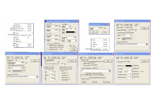
电子地球仪my world说明书

层
距离
设置海拔
优先位置
浏览
复制到剪贴板
帮助
关于
注册
隐藏
退出
地球尺寸程序项目网格质地地球尺寸程序项目网格质地地球尺寸程序项目网格质地地球尺寸程序项目网格质地
地球尺寸程序项目网格质地
显示
最小海拔
显示填充样式
格式
颜色
纹理文件
当前全球尺寸
小
中
大
地球在屏幕上的位置
地球的大小设置
左上
中心
右上
左下
右下
托盘图标和任务栏
仅任务栏
设置
仅托盘图标
层根目录
把地球置于其他项目的顶部
以漂浮的地球显示世界地图
投影
椭球体直角坐标墨卡托投影
显示网格
网格颜色
线条宽度
线条样示(立体)
经度间隔
纬度间隔经度
纬度
宽度
立体
网格
颜色
经度
纬度
起点
终点
线的方向
最短距离
最长距离
全球
清除
单元
距离
度数
小
中
大
满
视图管理器
显示质地
最小海拔
默认填充样式
样式
颜色
纹理文件
海拔。
中图版地理七年级上册《第一节 地球和地球仪》教学设计2

中图版地理七年级上册《第一节地球和地球仪》教学设计2一. 教材分析《地理七年级上册》第一节“地球和地球仪”主要介绍了地球的形状、运动、地球仪的概念、构成及使用方法。
本节内容是学生学习地理的基础,对于培养学生的空间观念和地理素养具有重要意义。
二. 学情分析七年级的学生具有一定的地理基础知识,但对于地球的形状、运动和地球仪的使用等方面的知识还比较模糊。
因此,在教学过程中,需要注重引导学生建立空间观念,通过观察、操作、思考、探究等活动,提高学生对地球和地球仪的认识。
三. 教学目标1.让学生知道地球的形状、运动,理解地球仪的概念、构成及使用方法。
2.培养学生观察、思考、探究的能力,提高空间观念。
3.激发学生学习地理的兴趣,培养学生的地理素养。
四. 教学重难点1.地球的形状、运动2.地球仪的概念、构成及使用方法五. 教学方法1.情境教学法:通过设置情境,让学生在实际操作中感受地球的形状、运动和地球仪的使用。
2.问题驱动法:提出问题,引导学生思考、探究,激发学生的学习兴趣。
3.合作学习法:分组讨论,共同完成任务,培养学生的团队协作能力。
六. 教学准备1.地球仪模型2.地球仪使用说明书3.PPT课件4.教学视频七. 教学过程1.导入(5分钟)利用PPT课件展示地球的图片,引导学生观察地球的形状,激发学生的学习兴趣。
2.呈现(10分钟)教师简要介绍地球的形状、运动,展示地球仪的实物模型,让学生初步了解地球仪的构成。
3.操练(10分钟)学生分组讨论,根据地球仪使用说明书,尝试操作地球仪,了解地球仪的使用方法。
教师巡回指导,解答学生疑问。
4.巩固(10分钟)教师提出问题,引导学生思考、探究地球的形状、运动和地球仪的使用方法。
学生回答问题,巩固所学知识。
5.拓展(10分钟)观看教学视频,了解地球仪在实际应用中的重要作用。
学生结合所学知识,讨论地球仪在地理学习中的应用。
6.小结(5分钟)教师总结本节课的主要内容,强调地球的形状、运动和地球仪的使用方法。
2024年人教版七年级地理上册第一章 地球 地球与地球仪

地球与地球仪第1课时地球的形状和大小地球的模型——地球仪设计说明本节课内容比较抽象,因此要从学生熟悉的地理事件入手,注重学生的参与度,让学生在参与中学习,在快乐中学习。
利用视频等多媒体手段培养其对地理学科的兴趣;通过制作地球仪培养其地理实践力的学科素养。
学习目标1.回顾人类认识地球形状的过程,并能够列举出相关的生活实例。
2.能够利用相关数据准确描述地球的大小,感知地球仪的用途。
重点难点重点:学会利用相关地理现象和数据说明地球的形状和大小。
难点:学会观察和使用地球仪。
教学方法读图分析法、合作探究法、概括归纳法等。
教学过程一、预习检查完成《七彩作业》知识梳理部分的内容。
二、学习任务一教学模块师生活动设计意图教师:出示太阳系图片、中国空间站拍摄的地球照片,请同学们找到地球,观测其形状特点。
学生:球体。
教师:今天,我们非常容易得出的一个结论,人类却经历了漫长的过程,下面就学习今天的课程——地球与地球仪。
结合中国空间站拍摄的影像,旨在培养学生的民族自豪感。
教师:(展示图片)人类对地球形状的认识,经历了漫长的过程。
阅读教材第11页内容,了解人类探究地球形状经历了哪几个阶段。
学生:第一阶段:“天圆地方”的设计理念在中国古代的建筑、货币等方面的表现。
第二阶段:人们根据太阳、月亮的形状,推测地启发引导学生思考、观察生活,并且通过对知识点的探究,使学生明白一个真理的发现需要球也是个球体。
第三阶段:麦哲伦船队环球航行的视频资料,让我们感悟科学探索精神。
第四阶段:中国航天史的光辉成就让学生感知中国航天事业的发展,建立初步的科学宇宙观,树立爱国意识。
(承转)我们在了解地球形状的过程中,也了解了地球的大小。
教师:运用平均半径、赤道周长和表面积等数据可以描述地球的大小。
学生:地球的最大周长约4万千米,平均半径6 371千米,表面积约5.1亿平方千米。
教师拓展:通过数据分析,认识到地球是两极稍扁、赤道略鼓的不规则的椭圆球体。
多方考证,不能简单地下定论。
地球仪—浙教版七级科学上册PPT公开课

1、纬线相交吗?
相互平行
2、纬线是圆还是半圆?
圆
3、各条纬线的长度是否相 等?
赤道最长,两 极缩成点
4、纬线指示什么方向?
指示东西方向
5、共有几条纬线,如何分?
无数条。除0 °纬线外,其他度数的纬线都有 两条。
南北纬的划分:
北极
0°纬线: 赤道
北纬: 赤道以北的纬度(0-90°)
(N) 北极:北纬90°
东经160度
划分标准:20°W、 160°E
为了避免把一些大陆、地区、国家分在两个半球。
2、纬线和纬度
在南北两极中间,与两极等距,并且与经线 垂直的线叫做赤道。
与赤道平行的线叫纬线。 赤道的纬度为0°。
赤道以北为北纬,北极 的纬度北纬 90°。
赤道以南为南纬,南极 的纬度南纬 90°。
仔细观察地球仪,找出纬线特点?
赤道 地球仪上最长的纬线
回归线 23.5°N 为北回归线,23.5°S 为
南回归线。
极圈 66.5°N为北极圈, 66.5° S为南极圈
1、经线和经度
地球仪上连接南北两极 的线叫做经线,也叫子午线。
给不同的经线标注的不 同度数叫做经度。
国际上规定,通过英国 伦敦格林尼治天文台的那条 经线为0°经线,也叫本初 子午线。
赤道
900
600 北 300 纬 North
00
南纬: 赤道以南的纬度(0-90°) (S) 南极:南纬90°
300 南 600 纬 South
南极 900
判断
5°N 为北回归线,23.
划分标准:20°W、 160°E
第一课时2地.球南仪 北纬度的判断
思考:如何划分东西半球?
- 1、下载文档前请自行甄别文档内容的完整性,平台不提供额外的编辑、内容补充、找答案等附加服务。
- 2、"仅部分预览"的文档,不可在线预览部分如存在完整性等问题,可反馈申请退款(可完整预览的文档不适用该条件!)。
- 3、如文档侵犯您的权益,请联系客服反馈,我们会尽快为您处理(人工客服工作时间:9:00-18:30)。
LED地球仪灯使用说明书
操作灯具前请仔细阅读说明书
灯具参数:
电压:AC90-240V
功率:200w
频率:50-60Hz
光源:10颗四合一LED灯珠
通道:15/22/53CH
控制模式:DMX512/主从模式/声控模式
水平运动:540°或无极模式(16比特精准扫描)
垂直运动:270°或无极模式(16比特精准扫描)
频闪:1-25次/秒或随机频闪
显示:LCD 液晶屏中英文显示
净重:9KG
尺寸:38*31*46cm(一装一纸箱)
产品菜单功能介绍:
1、地址码设置
地址码设置功能可为灯具设置相应的地址码,按ENTER进入该功能,通过按UP,DOWN 上上下键进行数值调整,然后按ENTER 键进行确认保存当前设置并退出。
2、工作模式
该功能可对灯具工作模式进行设置,按ENTER键进入该功能,通过UP,DOWN上下键进行工作模式选择。
工作模式循环展示,有DMX512,慢,快,声控,和从机模式。
选定工作模式后按ENTER键进行确认保存并退出。
DMX512:控台模式
慢速:慢速自走模式
快速:快速自走模式
声控:声控模式
从机:主从机模式
3、水平反转设置
该功能可对灯具进行水平反向运动设置,按ENTER键进入该功能。
按UP和DOWN键进入反向模式选择。
最后按ENTER键进行确认保存并退出。
4、垂直反转设置
该功能可对灯具进行垂直反向运动设置,按ENTER键进入该功能。
按UP和DOWN键进入反向模式选择。
最后按ENTER键进行确认保存并退出。
5、显示设置
该功能是针对灯具显示屏背光时间设置的操作项。
按ENTER键进入该功能,按UP和DOWN键进行该选项的设置。
最后按ENTER键进行确认保存并退出。
6、通道模式设置
该功能是对灯具进行通道模式选择与设置的选项。
通道模式有15.22.53三种通道模式。
按ENTER键进行功能选择,按UP和DOWN键进行选择,按ENTER键进行确认保存并退出。
53通道模式
22通道模式
15通道模式
7、恢复出厂设置
恢复出厂设置,灯具会恢复到出厂前的状态,用户的相关设置也将被清除。
8、重启
选择此功能后,等三秒钟,灯具会自动重启一次。
9、水平,垂直校正
用户选择此功能,5秒后进入水平和垂直微调校正功能,通过按UP 和DOWN 键进行初始位置校正,然后按ENTER键进行确认保存。
10、白平衡设置
用户按MENU键并保存5秒,设备将进入LED白平衡设置功能。
按UP和DOWN键对RGBW 各色进行设置,然后按ENTER进行确认保存并退出。
倒挂操作简图
灯具内部结构拆解简图
灯具的维修与保养
清洁和保养
灯具设备需要进行日常清洁维护。
灯具的使用寿命与灯具的维护和使用环境相关。
进行相关清洁维护前,请切断电源。
光学透镜精致且有镀膜,所以请勿用腐蚀性或有损透镜的物质擦拭。
请使用柔软的纸巾,或吹风机去除透镜外面灰尘污渍。
警告:
此灯具属于专业设备,只有具有专业人士才可进行灯具的安装与操控。
同时注意避免因操作不当而引发的烫伤,紫外线照射,设备坠落等损害事故。
操作该灯具设备前,请仔细阅读说明书并遵循安全操作指示。
如有问题,请向当地经销商,厂家或专业人士进行咨询。
为避免灯具坠落砸伤,当悬挂灯具设备时,请确认支撑物至少能承重10倍此灯具设备重量。
安装设备前,请确认挂钩无损坏,并加装保险绳以防万一。
