超声波探伤记录通用表格、模板
锻件超声波探伤报告记录(大平底)47013-汉威
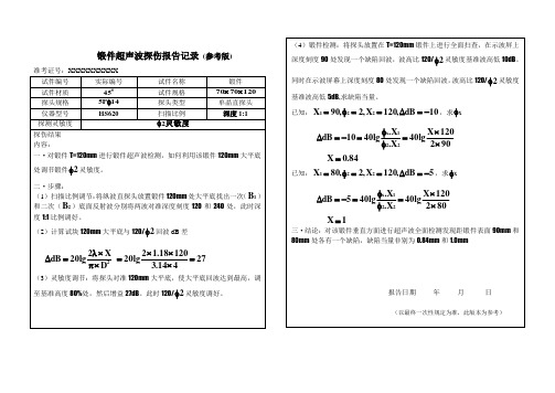
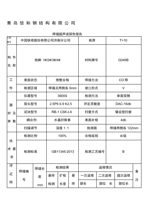
锻件超声波探伤报告记录 (参考版)准考证号:XXXXXXXXXX 试件编号 实际编号试件名称 锻件试件材质 #45试件规格 1207070⨯⨯探头规格 14P 5φ探头类型 单晶直探头 仪器型号 HS620扫描比例深度1:1探测灵敏度灵敏度2φ探伤结果 内容:一·对锻件T=120mm 进行锻件超声波检测,如何利用该锻件120mm 大平底处调节锻件2φ灵敏度。
二·步骤:(1)扫描比例调节:将纵波直探头放置锻件120mm 处大平底找出一次(1B )和二次(2B )底面反射波分别将两波对准深度刻度120和240处,此时深度1:1比例调好。
(2)计算试块120mm 大平底与120/2φ回波dB 差27414.312018.12lg 20D X 2lg20dB 2=⨯⨯⨯=⨯π⨯λ=∆ (3)灵敏度调节:将探头对准120mm 大平底,使大平底回波达到最高,调至基准高度80%处,然后增益27dB 。
此时120/2φ灵敏度调好。
(4)锻件检测:将探头放置在T=120mm 锻件上进行全面扫查,在示波屏上深度刻度90处发现一个缺陷回波,波高比120/2φ灵敏度基准波高低10dB 。
同时在示波屏幕上深度刻度80处发现一个缺陷回波,波高比120/2φ灵敏度基准波高低5dB ,求缺陷当量。
已知:10dB ,120X ,2,90X 221-=∆==φ=,求X φ902120X lg40X .X .lg4010dB 221x ⨯⨯=φφ=-=∆84.0X =已知:5dB ,120X ,2,80X 221-=∆==φ=,求X φ802120X lg40X .X .lg 405dB 221x ⨯⨯=φφ=-=∆ 1X =三·结论:对该锻件垂直方面进行超声波全面检测发现距锻件表面90mm 和80mm 处各有一个缺陷,缺陷当量非别为0.84mm 和1.0mm报告日期 年 月 日(以最终一次性规定为准,此版本为参考)。
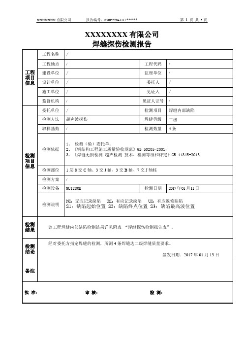
焊缝探伤检测报告(超声波)模板
12
--
--
--
--
--
--
--
--
Ⅰ级
NI
以下空白
H
(mm)
波高区域
波幅
(SL±dB)
指示长度
S2-S1(mm)
-3层、-2层、-1层(见-4层部位)牛腿、及框架梁上、下600mm范围
8
--
--
--
--
--
--
--
--
Ⅰ级
NI
9
--
--
--
--
--
--
--
--
Ⅰ级
NI
10
--
--
--
--
--
--
--
--
Ⅰ级
NI
11
--
--
--
--
--
--
--
--
Ⅰ级
--
--
--
--
Ⅰ级
NI
2
--
--
--
--
--
--
--
--
Ⅰ级
NI
3
--
--
--
--
--
--
--
--
Ⅰ级
NI
4
--
--
--
--
--
--
--
--
Ⅰ级
NI
以下空白
一次返修总长:/ mm
二次返修总长; / mm同一部位经/次返修后合格。
序号
缺陷位置
缺陷尺寸
评定
等级
备注
S1
(mm)
S2
(mm)
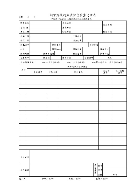
钢管焊缝超声波探伤检查记录表
试块
检验焊缝总长:mm;一次返修总长:mm;二次返修总长:mm;同一部位经次返修后合格
序号
探伤结果及返修情况
焊缝编号
检验长度
显示情况
一次缺陷编号
二次缺Байду номын сангаас编号
自检意见
监理意见
原始记录本
表号
册号
页码
序号
施工员:桥梁工程师:质检工程师:监理工程师:
页码共页
钢管焊缝超声波探伤检查记录表
JTG/TF50-2011公路桥涵施工技术规范编号:
项目名称
施工单位
施工日期
合 同 段
监理单位
单位工程
检验单位
检测日期
分部工程
工程部位
分项工程
墩(台)号
桩基编号
检验规程
验收标准
材料
厚度(mm)
焊接种类
焊接方法
焊缝数量
探伤面状态
检验范围
探伤时机
仪器型号
耦合剂
探伤方式
超声波探伤报告样表原版

Ultrasonic Examination ProcedureEPRO CONSTRUCTION QUALITY MANUALPage Date Revision Document No 1 / 25 01.03.2006 3 QM-QP-115ULTRASONIC EXAMINATION PROCEDUREFor Approval For Implementation3 2 1 0 Rev.01.03.2006 13.02.2006 18.01.2006 18.12.2005 DateY.A. Y.A. Y.A. Y.A. PreparedA.Ş. A.Ş. A.Ş. A.Ş. Q.C.M.E. M.E. M.E. M.E. ApprovedCode Editions revised Client Comments Par. 12.1 Revised First Issue Revision RecordUltrasonic Examination ProcedureEPRO CONSTRUCTION QUALITY MANUALPage Date Revision Document No 2 / 25 01.03.2006 3 QM-QP-115CONTENTS PRG 1.0 2.0 3.0 4.0 5.0 6.0 7.0 8.0 9.0 10.0 11.0 12.0 13.0 14.0 TITLE PURPOSE SCOPE REFERENCES PERSONNEL QUALIFICATION DEFINITIONS AND ABBREVIATIONS RESPONSIBILITIES GENERAL CALIBRATION TECHNIQUE EXAMINATION COVERAGE SAFETY AND ENVIRONMENT DOCUMENTATION ACCEPTANCE CRITERIA REPAIR PAGE 3 3 3 3 3 4 4 6 14 22 22 22 22 23Ultrasonic Examination ProcedureEPRO CONSTRUCTION QUALITY MANUALPage Date Revision Document No 3 / 25 01.03.2006 3 QM-QP-1151.0PURPOSE The purpose of this procedure is to describe the requirements for conducting Ultrasonic Testing by highly qualified personnel and equipment.2.0 2.1SCOPE This procedure defines the approach methods to be used by EPRO to carry out Ultrasonic A-scan Examination of welds in ASME Code Works and configurations joining in piping components tanks, pressure vessels and pressure vessel attachments etc. to detect weld discontinuities. The procedure shall cover the examination of carbon manganese steels, alloy steels and stainless steels. REFERENCES ASME Section V Article 4 & 5 ASME Section VIII Div 1 2 ASME Section I ASME B31.1 SNT TC-1A QM-WP-102 Ultrasonic Examination 2004 Ed. 2004 Add. Pressure Vessel 2004 Ed. 2004 Add Power Boilers 2004 Ed. 2004 Add Power Piping 2004 Edition 2004 Add ASNT Recommended Practice EPRO Written Practice for NDT Personnel Certification3.0 3.14.0 4.1.1PERSONNEL QUALIFICATION All personnel to carry out ultrasonic testing shall be qualified and certified according to EPRO Written Practice for NDT Personnel Certification based on SNT-TC-1A. For acceptance evaluation, Level II shall be the minimum requirement. Level I may perform straight beam inspections and acceptance evaluation (e.g. lamination check). DEFINITIONS AND ABBREVIATIONS Activity: One of the organizational elements of agency of the EPRO Approval: Requires dated signature by the approving person. ASME : American Society of Mechanical Engineers ASME CODE : The ASME Boiler and Pressure Vessel Code, Section I, Section VIII Division I & 2, Section V and Section IX, ASME B 31.1 and the National Board Inspection Code ASNT : American Society of Nondestructive Inspection Authorized Inspection Agency : An inspection organization which provides code inspections. Such Authorized Inspection Agency shall have a valid service agreement for code inspection with EPRO and shall be accredited by ASME. Authorized Inspector : The Authorized Inspector is employed by the Authorized Inspection Agency and is the independent thirt-party inspector required by the ASME Code. The Authorized Inspector shall hold a valid National Board Commission, issued by the National Board of Boiler and Pressure Vessel Inspectors, with an A- or B- endorsement. Certification: Written testimony of qualification5.0 5.1 5.2 5.3 5.45.5 5.65.75.8Ultrasonic Examination ProcedureEPRO CONSTRUCTION QUALITY MANUAL5.9Page Date Revision Document No 4 / 25 01.03.2006 3 QM-QP-115Certifying Authority: The person or persons properly designated in the written practice to sign certification on behalf of the employer Code Work : All activities necessary to construct Code products, including design, procurement, material control, fabrication, site construction, examination, test, inspection, certification and Code stamping. Documented: The condition of being in written form. Evaluation: The determination of the significance of relevant indications. Interpretation: The determination of whether indications are relevant or nonrelevant. Method: One of the disciplines of Nondestructive Inspection or testing (e.g. ultrasonic) within which different techniques exist. Procedure: A detailed, written instruction for conducting NDI or NDT or certifying personnel. All procedures shall be approved by a Level III and/or QA Manager Other standard definition of terms relating to Ultrasonic Examination shall be as recorded in ASTM Section V Article SE-1316. ABREVIATIONS • • • • • • AI : Authorized Inspector AIA : Authorized Inspector Agency AIS : Authorized Inspector Supervisor QC : Quality Control QA Manager : Quality Assurance Manager UT: Ultrasonic Testing5.105.11 5.12 5.13 5.145.155.165.176.0 6.1 6.2 6.3RESPONSIBILITIES Level III shall be responsible for preparing, reviewing and if required, revising this procedure. QA Manager shall be responsible for approving the procedure. UT Level II shall be responsible for performing ultrasonic inspections, supervising UT Level I and submitting the reports to QA Manager. UT Level I may perform straight beam inspection like lamination checks under UT Level II and/or Level III supervision GENERAL REQUIREMENTS FOR ULTRASONIC EQUIPMENT ULTRASONIC APPARATUS The ultrasonic apparatus is to cover a frequency range of at least 1.0 –6.0 MHz. The ultrasonic apparatus is to be fitted with a calibrated gain regulator with a maximum of 2 d B per step. The ultrasonic apparatus is to be equipped with a flat screen extending to the front of the apparatus so that a reference curve can be drawn directly on the screen.6.47.0 7.1 7.1 7.1.1 7.1.27.1.3Ultrasonic Examination ProcedureEPRO CONSTRUCTION QUALITY MANUAL7.1.4Page Date Revision Document No 5 / 25 01.03.2006 3 QM-QP-115The ultrasonic apparatus must be able to work with both combined and separated transmitter and receiver probe. Any equipment meeting the requirements of this section may be used for inspections. PROBES (TRANSDUCERS) Normal probes which are utilized, are to cover a frequency range of 1.0 –6.0 MHz. Typical values are 1.0 MHz, 2.0 MHz, 4.0 MHz and 6.0 MHz. The angle probes which are used, are to cover a frequency range of 1.0 –6.0 MHz. Typical values are 1.0 MHz, 2.0 MHz, 4.0 MHz and 6.0 MHz. Probes used shall not to cause more noise than that an echo with a height of %5 of full screen height can easily be distinguished from the normal level of noise. On surfaces with a small radius of curvature such as pipes with a small diameter. It may be necessary to adjust the probe shoe to attain sufficient contact between the material and the probe. COUPLANT A satisfactory couplant in either fluid or paste from is to be used to transfer the ultrasound from the probe to the material. Oil, grease, glycerin or paste is well suited to this purpose (A cellulose gum is particularly suitable as it can be removed with water after inspection completed). Couplant brand name or type used for examination shall be recorded on ultrasonic examination report. CALIBRATION BLOCKS FOR RANGE AND ANGLE CALIBRATION For the calibration of the ultrasound apparatus range scale and the angular determination of angle probes, an IIW calibration block or a V2 calibration block is to be used (DIN 54122). These are shown on Figure 1. Calibration blocks shall be retained in a safe place and prevented against corrosion or damage and controlled before use.7.1.5 7.2 7.2.17.2.27.2.37.2.47.3 7.3.17.4 7.4.1IIW (V1) CALIBRATION BLOCKV2 CALIBRATION BLOCK FIGURE 1. CALIBRATIONS BLOCKS OTHER AIDS7.5Ultrasonic Examination ProcedureEPRO CONSTRUCTION QUALITY MANUALPage Date Revision Document No 6 / 25 01.03.2006 3 QM-QP-1157.5.1“Ultrasound slide rules” or tables for determining the position of defects can be used. Similarly, a slide gauge for measuring the distance from the angle probe to the defect can be used as well as any other necessary measuring and marking equipment. INSPECTION TECHNIQUE Direct contact techniques with straight beam (normal incident longitudinal wave) and angle beam (shear waves) shall be used. SURFACE PREPARATION CONTACT SURFACE The contact surface is to be free of weld splatter and any other substance which may impede the free movement of the probe of hinder the transmission of ultrasound to the material. A light grinding of the surface may be necessary. The finish on the scanning surfaces of the calibration block shall be representative of the scanning surface finish on the component to be examined. WELD REINFORCEMENT Grinding of the weld reinforcement (cap pass) may be necessary if reflections received is suspicious and has the possibility of coming from the cap pass or from weld root. If accessible, the same applies to weld root. CALIBRATION RANGE CALIBRATION Normal probe range calibration is to be carried out with an IIW calibration block, a V2 calibration block or on a defect free known thickness calibration block of the same material to be inspected (see Figure 2). The range scale is to be selected such that there are always at least 2 back wall echoes (reflections) on the screen when one is calibrating. The first echo is put at 75% of full screen height (FSH) and with the test range selector and the zero point control of the ultrasonic apparatus one positions the echoes in such a way that the distance between them represents the thickness of the calibration block. Angle probe range calibration is to be carried out with an IIW calibration block or a V2 calibration block (see Figure 3). The probe index is to be determined by placing the probe as shown in Figure 3-a by maximizing the echo height received from the cylindrical surface of 100 mm radius (IIW) or 25 mm (V2). The echo height is to be adjusted to approximately 75% FSH. The probe index can now be measured between the scribe mark on the calibration block and probe front surface. For easy usage, index point may be marked on a stickers attached on the sides of the probe. The range scale is calibrated by placing the probes on IIW and receive echoes shown in Figure 3b or by placing V2 and receive echoes as shown in Figure 3-c. In these positions, always 2 echoes shall be visible on the screen. The echo heights shall be maximized, and the first echo shall be adjusted at ~75% FSH. With the aid of the test range selector and zero point control (depends on the UT instrument), the echoes are positioned so that they fall at 100 mm and 200 mm for the IIW block (see figure 3-b). The V2 block generates echoes at 25 mm and 100 mm or 50 mm and 125 mm (see figure 3-c).7.6 7.6.17.7 7.7.1 7.7.27.7.37.8 7.8.18.0 8.1 8.1.18.1.2Ultrasonic Examination ProcedureEPRO CONSTRUCTION QUALITY MANUALPage Date Revision Document No 7 / 25 01.03.2006 3 QM-QP-115FIGURE 2. NORMAL PROBE RANGE CALIBRATIONFIGURE 3 ANGLE PROBE RANGE CALIBRATION 8.2 8.2.1 PROBE ANGLE CHECK The probe angle is to be checked on the IIW block using the probe index found under 8.1.2, the echo from the circular Perspex reflector is maximized and adjusted at ~75% FSH. The probe angle shall be read from the index point on the probe and scribed angles on the calibration block (see figure 4).FIGURE 4. CHECKING THE PROBE ANGLEUltrasonic Examination ProcedureEPRO CONSTRUCTION QUALITY MANUALPage Date Revision Document No 8 / 25 01.03.2006 3 QM-QP-1158.3 8.3.1CORRECTION FOR DEVIATION IN SOUND VELOCITY Calibration as mentioned under 8.1 and 8.2 on IIW block or V2 block, is only valid for inspection of steel with approximately the same sound velocity of the standard calibration block used (about 5900 m/s compressional wave velocity, 3200 m/s transverse wave velocity). If working with steel qualities which have different sound velocities, the probe angle is to be corrected in accordance with the new velocity, or using a calibration block produced from the same material to be inspected. Any deviation in velocity may be investigated by calibrating the range scale on the IIW block for a straight beam probe and measure a known thickness of new material with the same calibration. SENSITIVITY CALIBRATION Calibration of the sensitivity is carried out by utilizing drilled holes as reference reflectors. Holes may be drilled in the actual production material or in reference blocks. Moving probe towards reflectors, a reference curve may be drawn on the screen ether by a crayon marker or by electronic circuit of the UT instrument as described in 8.5.8.48.5REFERENCE CURVE In order to compensate for attenuation and sound beam spread with increasing sound path a reference curve is to be constructed, which is drawn on to the screen of the ultra –sound apparatus, and which gives the echo height from the same reflector at varying distances between probe and reflector.8.5.1The reference curve is to be constructed by using a side drilled hole or surface notch as reference reflector. Side drilled hole or notch may be placed either directly in the production material or in a reference block made from the production material, or possibly from material with the same acoustic properties and surface condition of production material. The reference block shall have the same thickness (T) as the production material (see figure 5-b). When two or more thicknesses are involved, T shall be determined by the average thickness of the weld. Alternatively a calibration block thickness having greater base material thickness may be used provided the reference reflector size is based upon the average or smaller weld thickness. When the block thicknesses have ±25mm spans two weld thickness ranges, the block’s use shall be acceptable in those portion of each thickness range covered by 25 mm of the calibration block’s thickness. As an example, a calibration block with a thickness of 38 mm may be used for weld thicknesses of 13 mm to 64 mm. For examinations in materials where the examination surface diameter is greater than 508 mm (20”), a block of essentially the same curvature (see Figure 5-a), or alternatively, a flat basic calibration block, shall be used (see Figure 5-b). The basic calibration block shall be curved (see Figure 5-a) for materials with diameters 508 mm (20”) and less. Except where otherwise stated in this procedure, a single curved basic calibration block may be used to calibrate the examination on surfaces in the range of curvature from 0.9 to 1.5 times the basic calibration block diameter. For example, an 203 mm (8”) diameter curved block may be used to calibrate the examination on surfaces in the range of curvature from 183 mm to 305 mm (7.2” to 12”) diameter. The drilled hole shown in Figure 5-b is used as reference reflector and is to be drilled parallel to the examination surface of the reference block or the production material. The positions and the diameter of the drilled holes are given in Figure 5-b.8.5.28.5.38.5.48.5.58.5.6Ultrasonic Examination ProcedureEPRO CONSTRUCTION QUALITY MANUALPage Date Revision Document No 9 / 25 01.03.2006 3 QM-QP-115* Notches shall be located not closer than T or 25 mm (1”), whichever is greater, to any block edge or to other notches. GENERAL NOTES: a) b) c) d) e) The minimum calibration block length (L) shall be 200 mm (8”) or 8T, whichever is greater. For OD 100 mm (4”) or less, the minimum arc length shall be 270 deg. For OD greater than 100 mm (4”), the minimum arc length shall be 200 mm (8”) or 3T, whichever is greater. Notch depths shall be from 8% T minimum to 11% maximum. Notch widths shall be 6 mm (1/4”) maximum. Notch lengths shall be 25 mm (1”) minimum. Maximum notch width is not critical. Notches may be EDM or with end mills up to 6 mm (1/4”) in diameter. Notch lengths shall be sufficient to provide for calibration with a minimum 3 to 1 signal-to-noise-ratio.FIGURE 5-a CALIBRATION BLOCK FOR PIPEWeld thickness (t) mm ≤ 25 >25 to ≤ 50 >50 to ≤100 >100Calibration Block Thickness (T) mm 19 or t 38 or t 75 or t T ± 25Hole mm 2,5 3 5 **DiameterNotch Dimentions Depth=2% T Width=6 mm max. Length=25 mm max.* Minimum dimension **For each increase in weld thickness of 50 mm, a fraction thereof over 100 mm, the hole diameter shall increase 1,5 mm. GENERAL NOTES: a) b) c) d) e) f) Holes shall be drilled and reamed 38 mm deep minimum, especially parallel to the examination surface. For components equal to or less than 500 mm in diameter, calibration diameter shall meet the requirements of 8.5.5. two sets of calibration reflectors (holes, notches) oriented 90 deg from each other shall be used. Alternatively, two curved calibration blocks may be used. The tolerance for hole diameter shall be 0.8 mm. The tolerance of hole location through the calibration block thickness (i.e. distance from the examination surface) shall be 3 mm. All holes may be located on the same face of face (side) of the calibration block provided care is exercised to locate all the reflectors (holes, notches) to prevent one reflector from affecting the indication from other another reflector during calibration. Notches may also in the same plane as the inline holes. A sufficient number of holes shall be provided for both angle and staright beam calibratios at the ¼ T, ½ T and ¾ T depths. Minimum notch depth shall be 1.6% T and maximum notch depth shall be 2.2% T plus the thickness of claddind, if present. Maximum notch width is not critical. Notches may be EDM or with end mills up to 6 mm in diameter.FIGURE 5-b NON-PIPING CALIBRATION BLOCKSUltrasonic Examination ProcedureEPRO CONSTRUCTION QUALITY MANUALPage Date Revision Document No 10 / 25 01.03.2006 3 QM-QP-1158.5.6The drill hole as shown on figure 5b, is used as a reference reflector and is to be drilled parallel to the contact surface in the reference block or the production material. The positioning and the diameter of the drill hole are given in figure 5b. When constructing a reference curve with angle probe, the first point on the reference curve is to be determined by placing the probe in position A as shown on figure 6 a for plate thicknesses < 10 mm, as shown on Figure 6-b for plate thicknesses >25 mm. The sound path distance from point A to the reference reflector must not be less than 0.6 N, where N is the near field length for the relevant probe. The echo height from the drill hole is maximized and the gain control is adjusted to 75% FSH. This gain setting is called the primary gain and shall be recorded. Without changing the primary gain, the probe is positioned in half skip distances as shown on Figure 6-a, 6-b and 6-c. And the respective echo heights are marked on the screen. These points are connected by a smooth line with a length which covers the area to be inspected. This is the reference curve. When the reference curve has been set up, another curve, which is 20% of the reference curve, is to be drawn in, see figures 6-a, 6-b and 6-c.8.5.7(a)(b)(c)FIGURE 6 CONSTRUCTION OF REFERENCE CURVES. THE NUMBERS IN BRACKKETS ABOVE PROBES GIVE NUMBERS OF EIGHTS OF A FULL SKIP DISTANCEDate 01.03.2006 Revision 3CONSTRUCTION QUALITY MANUALDocument NoQM-QP-1158.5.8 If the reference curve by excessive sound paths falls below 25 % of full screen height the gain in this area is to be increased in the following way.The probe is placed in position B (alternatively C) as shown on Figure 7 and the echo height is maximized and adjusted at 75% FSH. The new primary gain is noted. Without altering this, the probe is moved to position C (alternatively D) and a new reference curve is set up on the screen of the ultrasonic apparatus and its 20 % curve to be used. The primary gain will now be greater than for the original reference curve and applies only for inspection in this area.FIGURE 7. INCREASING GAIN FOR EXCESSIVE SOUND PATH8.5.9 For inspecting weld joints less than 50 mm with a straight beam probe, a reference curve defined below shall be constructed:The production material or reference block with reference reflector described in 8.5.1 through 8.5.6, the probe is placed position A of Figure 8-a. The echo height is maximized to 50% FSH. The primary gain is noted. The reference curve is drawn as a horizontal line on the screen.8.5.10 For inspecting weld joints greater than 50 mm with a straight beam probe, a reference curve defined below shall be constructed:The production material or the reference block and the reference reflectors described in 8.5.1 through 8.5.6, the probe is placed over the drilled hole position A of Figure 8-b, the echo height is maximized to 50 % FSH. This gain setting is the primary gain and is noted. Without altering this, the probe is moved to position B, the echo height is marked on the screen. The two points are connected with a straight line, extending until it covers the interested area. This is the reference curve.Date 01.03.2006 Revision 3CONSTRUCTION QUALITY MANUALDocument NoQM-QP-115abFIGURE 8 SENSITIVITY CALIBRATIONS FOR NORMAL PROBES8.5.11As shown on Figure 6-a, Figure 6-b and 6 c, the area of the reference curve between zero and the first point on the reference curve (A) is not used for defect evaluation. This zone is the near zone of the probe and in this zone it is very difficult to assess the discontinuity size. There is, however, nothing prevents using this zone for locating discontinuities. For example, when inspecting the root area of butt welds in thin plates with a face and root reinforcement; it is often very difficult to find incomplete penetration if this zone not used. Otherwise, the reinforcement shall be flush ground to find this kind of discontinuities but it is impossible to do so for long pipelines. When discontinuities found in the near field area, the defect evaluation shall be performed within the reference curve, i.e. the sound path to the defect is increased so that the echo from the defect remains within the reference curve area.8.5.12If the ultrasonic instrument has electronic distance/amplitude correction, this can be used for angle probes and normal probes. The echo height from the drilled hole in the production material or reference block is then to be adjusted to 75% FSH over the whole inspection range. The reference curve will thus be a horizontal line. The gain setting is noted as primary gain.8.5.13 Any possible differences in attenuation and surface condition between the reference block and the production material during inspection with angle probes shall be checked in the following way:Use two angle probes of the same type of probes used for inspection. The probes shall be placed on the production material as shown in Figure 9. One of the probes works as transmitter, whilst the other acts as receiver. The first echo is maximized and put at a certain height on the screen, for example 80% FSH. The gain setting is noted. Without altering this gain setting the probes shall be moved to the reference block and the echo height is noted. Any difference in echo heights between the two checks shall be measured in dB with the aid of gain control. If any difference found, correction shall be done as follows and the final value is called “corrected primary gain:• When the echo height from the production material is less than the echo height from thereference block, the difference, in dB, is to be added to the primary gain.Date 01.03.2006 Revision 3CONSTRUCTION QUALITY MANUALDocument NoQM-QP-115•When the echo height from the production material is greater than that from the reference block, the difference, in dB, is to be subtracted from the primary gain.FIGURE 9 ATTENUATION AND TRANSFER CORRECTION8.6 PERIODIC INSPECTION OF ULTRASONIC INSTRUMENT AND PROBESIn order to ensure at any time that the ultrasonic equipment is in order, the operator shall check the equipment during ultrasonic inspection.8.6.1 ULTRASONIC INSTRUMENT• Sensitivity calibration of equipment shall always be carried out prior to thecommencement of operations, • Every two hours,• Any time the instrument is switched OFF and ON,• Any time a part of instrument replaced (Cable, Probe etc.),8.6.2 Any time there is doubt about instrument calibration, the following checks should be performed:Date 01.03.2006 Revision 3CONSTRUCTION QUALITY MANUALDocument NoQM-QP-1158.6.2.1 Check the range with the aid of the IIW block or the V2 block.8.6.2.2 Check the corrected primary gain as defined in 8.5.13.8.6.2.3During the verification checks, any deviation found more than 10 % or that the reference amplitude has reduced by more than 20% or 2 dB, all welds inspected after last check shall be re-inspected.8.6.3 PROBES8.6.3.1 The probes shall be inspected frequently, before and after ultrasonic inspection. Angle probesused on rough surfaces shall be inspected ever two hours.8.6.3.2 Inspect the angle probe shoe for possible wear. If wear has caused an angle deviation ≥ 2° fromthe nominal value, the probe shall be changed. When changing a probe, the whole range calibration described in 8.1.2 shall be repeated.8.6.3.3 Normal probes shall be inspected by placing them on the production material or reference block,and at least three back wall echoes shall be visible when the first bottom echo is adjusted to 100 % FSH. The protective cover shall also be inspected and if it is worn out, it must be changed and the range calibration defined in 8.1.1 shall be repeated.9.0 TECHNIQUEThis procedure covers inspection of base metal by normal beam probe and inspection of weld joints by normal and angle beam probes.9.1 INFORMATION REQUIRED BEFORE INSPECTIONBefore inspection starts, the following information shall be provided to the UT Operator: • Material type • Bevel design • Welding procedure • Details of repairs done • Other factors effects the metallurgical structure of the material to be inspected (e.g. heattreatment).9.2 BASE METAL INSPECTIONBase metal inspection with a normal beam probe from both sides of the weld shall be performed to see if laminations, large variations in sound velocity and attenuation and thickness variations in the base material is present.9.2.1 Inspection of the base metal shall be carried out with a normal beam probe with a frequencybetween 2 and 6 MHz. The highest frequency which ensures good sound penetration shall be selected (see 7.2.1). After range calibration 8.1.1 and sensitivity calibrations 8.5.9 and 8.5.10, base metal on both sides of the weld joint which will transfer angle beam ultra-sound for inspection shall be inspected. Discontinuities in the base metal shall be assessed and corrected if necessary, to ensure the weld joint can inspected with angle beam probe without any negative affect. The extent of the discontinuity shall be plotted by half-value or 6 dB technique (see 9.3.5) 9.3 INSPECTION OF WELD JOINTSInspection of weld joints shall be performed to find possible:• Discontinuities in the base metal• Discontinuities in the weld metal and heat-affected zone • Lack of fusion between weld and base metal.Date 01.03.2006 Revision 3CONSTRUCTION QUALITY MANUALDocument NoQM-QP-1159.3.1A favorable probe angle in relation to the plate thickness for volumetric weld defects is given in Table I and Table II for weld joint inspections with and without reinforcement.Table I Weld Without ReinforcementPLATE THICKNESS, MM FAVOURABLE PROBE ANGLE5-15 70° 15 – 30 45°, 60°, 70° 30 – 60 45°, 60°, (70°) OVER 60 45°, 60°,Table II Weld With ReinforcementPLATE THICKNESS, MM FAVOURABLE PROBE ANGLE5-20 70° 20– 40 45°, 60°, 70° OVER– 40 45°, 60°, (70°)9.3.2When a weld joint inspected for lack of fusion, a favorable angle is the angle which gives incident sound normal to lack-of-fusion (~90 deg to the expected discontinuity orientation) (see Figure 10). The optimum angle for a V-grove joint design is given by the grove geometry and can be calculated as shown in Figure 10. If the calculated angle does not agree with any standard probe angle, the nearest larger probe angle is to be selected.FIGURE 10 DETECTION OF LACK OF FUSION9.3.3 The frequency shall be within the range of 1 –6 MHz, and shall selected as high as possible givingsatisfactory sound transmission.9.3.4 The gain to be used in the defect evaluation is the corrected primary gain. When inspecting fordiscontinuities, the gain shall be increased by 6 dB to increase the sensitivity for discontinuities with difficult orientation. Added 6 dB shall be reduced for defect evaluation.9.3.5 The extent of discontinuities for longitudinal direction shall be determined by the half-value or 6 dBmethod. This method can be used for both normal and angle beam probes (see Figure 11). The extent of the discontinuity shall be determined by finding maximum echo height in the middle of the discontinuity and 6 dB gain is added to this height. Subsequently, the probe moved towards the edge。
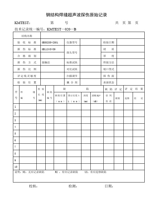
钢结构焊缝超声波探伤原始记录
缺陷位置(mm)
指示长度ΔL(mm)
(mm)
波幅SL+(dB)
估判
性质
返修
结论
1
2
3
4
5
6
7
8
9
10
说明:NI:无应记录缺陷RI:有应记录缺陷UI:有应返修缺陷
校核:检测:日期:
kmtest020b结构名称验收标准gb502052001仪器型号检验日期探伤标准gb1134589探头型号材质合格级别厚度探伤方式接触法标准试块焊接方法探伤比例对比试块坡口型式评定线灵敏度扫描调节探伤面检验位置藕合剂表面状态序号焊缝编号检验长度mm缺陷编号缺陷缺陷评定评定结果缺陷位置mm指示长度lmm深度mm波幅sldb估判性质级别返修结论12345678910说明
钢结构焊缝超声波探伤原始记录
KMTEST:第号共页第页
技术记录统一编号:KMTEST—020—B
结构名称
验收标准
仪器型号
检验日期
探伤标准
GB11345-89
探头型号
材质
厚度
接触法
标准试块
焊接方法
探伤比例
对比试块
坡口型式
扫描调节
探伤面
检验置
藕合剂
表面状态
序号
焊缝
编号
检验长度
(mm)
缺陷编号
缺陷
缺陷评定
探伤报告原始记录
DAC-16db
试块型号
RB-1 CSK-IA
扫查方式
锯齿型扫查
耦合剂
水基纤维素
表面补偿
4db
扫描调节
深度1:1
检测面
焊缝两侧各122mm
技
术 要 求
检测比例
100%
合格级别
H级
检测标准
GB11345-2013
检测工艺编号
B
评
疋
结
焊缝编
号
焊缝长 度
mm
检测结果
返修情况
备
注
最终
检测
扩检
长度
最
检测工艺编号
B
评
焊缝编焊缝长
检测结果
返修情况备
疋
结
果
号
度
mm
最终
检测
总长
度mm
扩检
长度
mm
最
终 级 别
一次返修
二次返修
超次返修
注
部
位
数
( 处)
长
度
mm
部位 数
(处
)
长
度
mm
部位 数
(处
)
长
度
mm
001
9406
9406
II
级
合格
002
9406
9406
I
级
合格
缺陷及返修情况说明
检测结果
1最高返修次数为次。
修整合格
焊接方法
CQ焊
检测区域
焊缝及两侧各5mm
坡口形式
V
器
材 及
参 数
仪器型号
3600S
合肥NSK厂房--探伤记录表

中铁四局集团钢结构有限公司 超声波探伤检验记录表工程名称 合肥 NSK 一期钢结构厂房工程构件名称 材 厚 质 度 构件编号 坡口形式 检测区域 表面状态 仪器型号 探头规格 验收标准焊缝 为 筋板与翼缘板对 接焊缝施工班组:检验 焊缝及热影响区 次序 首次 检测○ 一次返修 检测○ 二次返修 检测○焊接方法 对比试块 表面补偿 扫描深度扫查方式 探伤灵敏度 检测比例 焊缝等级背面焊 缝 示 意 图背面钢柱焊缝示意图构件编号 焊缝编号 缺陷长度 缺陷深度 Ⅰ 评定等级 Ⅱ Ⅲ Ⅳ 检测结果 返修检测 结果中铁四局集团钢结构有限公司 超声波探伤检验记录表工程名称 合肥 NSK 一期钢结构厂房工程构件编号 焊缝编号 缺陷长度 缺陷深度 Ⅰ 评定等级 Ⅱ Ⅲ Ⅳ施工班组:检测结果 返修检测 结果检测结论: 检测人员 检测时间中铁四局集团钢结构有限公司 超声波探伤检验记录表工程名称 合肥 NSK 一期钢结构厂房工程构件名称 材 厚 质 度 构件编号 坡口形式 检测区域 表面状态 仪器型号 探头规格 验收标准 焊缝及热影响区 次序施工班组:检验 首次 检测○ 一次返修 检测○ 二次返修 检测○焊接方法 对比试块 表面补偿 扫描深度扫查方式 探伤灵敏度 检测比例 焊缝等级焊 缝 示 意 图钢架梁 焊缝示意图构件编号焊缝编号缺陷长度缺陷深度 Ⅰ评定等级 Ⅱ Ⅲ Ⅳ检测结果返修检测 结果中铁四局集团钢结构有限公司 超声波探伤检验记录表工程名称 合肥 NSK 一期钢结构厂房工程构件编号 焊缝编号 缺陷长度 缺陷深度 Ⅰ 评定等级 Ⅱ Ⅲ Ⅳ施工班组:检测结果 返修检测 结果中铁四局集团钢结构有限公司 超声波探伤检验记录表工程名称 合肥 NSK 一期钢结构厂房工程构件编号 焊缝编号 缺陷长度 缺陷深度 Ⅰ 评定等级 Ⅱ Ⅲ Ⅳ施工班组:检测结果 返修检测 结果检测结论: 检测人员 检测时间中铁四局集团钢结构有限公司 中铁四局集团钢结构有限公司 超声波探伤检验记录表工程名称 合肥 NSK 一期钢结构厂房工程构件名称 材 厚 质 度 构件编号 坡口形式 检测区域 表面状态 仪器型号 探头规格 验收标准 焊缝及热影响区 次序施工班组:检验 首次 检测○ 一次返修 检测○ 二次返修 检测○焊接方法 对比试块 表面补偿 扫描深度扫查方式 探伤灵敏度 检测比例 焊缝等级焊 缝 示 意 图示意图构件编号焊缝编号缺陷长度缺陷深度 Ⅰ评定等级 Ⅱ Ⅲ Ⅳ检测结果返修检测 结果中铁四局集团钢结构有限公司 中铁四局集团钢结构有限公司 超声波探伤检验记录表工程名称 合肥 NSK 一期钢结构厂房工程构件编号 焊缝编号 缺陷长度 缺陷深度 Ⅰ 评定等级 Ⅱ Ⅲ Ⅳ施工班组:检测结果 返修检测 结果中铁四局集团钢结构有限公司 超声波探伤检验记录表工程名称 合肥 NSK 一期钢结构厂房工程构件编号 焊缝编号 缺陷长度 缺陷深度 Ⅰ 评定等级 Ⅱ Ⅲ Ⅳ施工班组:检测结果 返修检测 结果检测结论: 检测人员 检测时间中铁四局集团钢结构有限公司 中铁四局集团钢结构有限公司 超声波探伤检验记录表工程名称 合肥 NSK 一期钢结构厂房工程构件名称 材 厚 质 度 构件编号 坡口形式 检测区域 表面状态 仪器型号 探头规格 验收标准 焊缝及热影响区 次序施工班组:检验 首次 检测○ 一次返修 检测○ 二次返修 检测○焊接方法 对比试块 表面补偿 扫描深度扫查方式 探伤灵敏度 检测比例 焊缝等级焊 缝 示 意 图示意图构件编号焊缝编号缺陷长度缺陷深度 Ⅰ评定等级 Ⅱ Ⅲ Ⅳ检测结果返修检测 结果中铁四局集团钢结构有限公司 中铁四局集团钢结构有限公司 超声波探伤检验记录表工程名称 合肥 NSK 一期钢结构厂房工程构件编号 焊缝编号 缺陷长度 缺陷深度 Ⅰ 评定等级 Ⅱ Ⅲ Ⅳ施工班组:检测结果 返修检测 结果超声波探伤检验记录表超声波探伤检验记录表超声波探伤检验记录表超声波探伤检验记录表超声波探伤检验记录表超声波探伤检验记录表超声波探伤检验记录表超声波探伤检验记录表超声波探伤检验记录表超声波探伤检验记录表超声波探伤检验记录表超声波探伤检验记录表超声波探伤检验记录表。
- 1、下载文档前请自行甄别文档内容的完整性,平台不提供额外的编辑、内容补充、找答案等附加服务。
- 2、"仅部分预览"的文档,不可在线预览部分如存在完整性等问题,可反馈申请退款(可完整预览的文档不适用该条件!)。
- 3、如文档侵犯您的权益,请联系客服反馈,我们会尽快为您处理(人工客服工作时间:9:00-18:30)。
距离
Ⅰ
1/3 T
Ⅱ
2/3 T
Ⅲ
3/4 T
Ⅳ
超过
Ⅲ级者
超过
Ⅲ级者
超过
Ⅲ级者
超过
Ⅲ级者
检验次序
□首次检验□一次复验□二次复验
其它情况说明:
检测:校核:
青岛有限公司
超声波探伤记录表
报告编号:第页共页
构件编号
焊缝编号
板厚(mm)
检测长度
(mm)
缺陷
编号
缺陷位置(mm)
波幅
(dB)
评定
等级
检测结果
X
Y
D
L
□返修
□符合
□返修
□符合
□返修
□符合
□返修
□符合
□返修
□符合
□返修
□符合
□返修
□符合
□返修
□符合
□返修
□符合
□返修
□符合
□返修
□符合
□返修
□符合
□返修
□符合
□返修
□符合
□返修
□符合
□返修
□符合
□返修
□符合
返修
□符合
备注:X — 0点至缺陷起点的距离,Y —缺陷至焊缝上边缘的距离,D —缺陷至检测面的深度,
L —缺陷指示长度
检测:校核:
青岛有限公司
超声波探伤记录表
报告编号:第页共页
检测单位
工程名称
接头种类
生产日期
焊接方法
检测日期
仪器型号
材质
探头
表面状态
表面补偿
试块
探伤时机
耦合剂
验收规范
检验等级
检测标准
合格级别
等级
板厚mm
板厚mm(T1)
板厚mm(T2)
板厚mm(T3)
距离-波幅曲线示意图
T
波
幅
判废线(RL) DAC-4dB
定量线(SL)DAC-10dB