EK312A.操作手册.
EK312A.操作手册
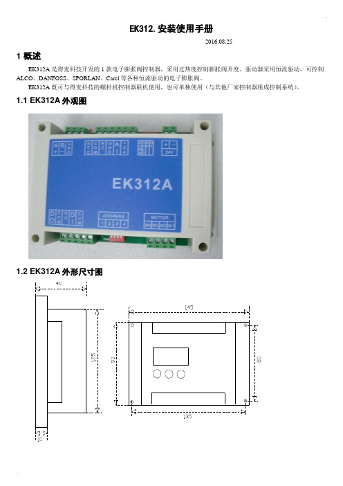
.EK312.安装使用手册-----2016.08.251 概述EK312A是得麦科技开发的1款电子膨胀阀控制器,采用过热度控制膨胀阀开度。
驱动器采用恒流驱动。
可控制ALCO、DANFOSS、SPORLAN、Carel等各种恒流驱动的电子膨胀阀。
EK312A既可与得麦科技的螺杆机控制器联机使用,也可单独使用(与其他厂家控制器组成控制系统)。
1.1 EK312A外观图1.2 EK312A外形尺寸图..1.3 EK312A 电气连接示意图EK312A电气连接示意图B-GA++-G TI DO W3W2W4AI +24G DI Com ComW1MotorB-GND A+ONOFF1234ON OFF1234O NO F FSW2JP2JP1JP3JP4JP5SW1VCCIout SW1地址1234OFF OFF 1ON OFF 2OFF ON 3ON ON4N LAC220VO N O FFSW212345V 10V举例1:12345123412312345612JP2-5设置为4-20mA输入O N O F FSW21234C V 5V 10V 举例2:JP2-5设置为0-10V输入O NO F FSW21234C V 5V 10V电子膨胀阀接线说明:ALCO膨胀阀:W4:白色W3:黑色W2:棕色W1:蓝色Danfoss膨胀阀:W4:黑色W3:白色W2:绿色W1:红色SPORLAN膨胀阀:W4:白色W3:黑色W2:绿色W1:红色Carel膨胀阀:W4:黄色W3:白色W2:棕色W1:绿色地址拔码说明:模拟输入拔码说明:报警输出启停开关电子膨胀阀24V电源输入压力传感器温度传感器通讯线运行故障通讯确认向上向下C V 0|10V0|5V 电压型电流型使用按键显示板备用注1:压力传感器接线:注2:压力传感器接线处,板内供电是24V ,如果传感器不是24V 供电,则要外接电源,之后将电源的负极接到板上的地(JP2-4)即可。
SA3C32A激光甲烷检测仪中文说明书

安全提示
请于使用本产品前仔细阅读以下内容以确保进行正确的操作。 为确保设备和操作者的使用安全,我们在本手册和产品主机上使用了安全标识来 指示几种安全警告类型。因此,请在实际操作本产品前阅读安全提示的内容以便 进行正确操作。
为了能清晰的指示伤害和损害的严重性和紧急性,根据假设因非正确操作而引起 的后 果, 我们将 安 全预 警标识 分 成了 DANGER( 危险 ),WARNING(警告 ) 和 CAUTION(注意)三个等级。基于安全考虑,这些预警包括了重要内容请务必小心 遵循。
寿命缩短。
运输时,请确保遵循以下安全指示: y 当探测器和充电器采用汽车运输时,请确保设备避免直接的振动和
晃动。 y 如探测器、电池或充电器发生故障需要返修寄送或其他情况时,请
在包装箱内放置防震材料。
5
V1.0.2A
警告
激光安全
根据 IEC60825-1 规定,本探测器使用的测量激光辐射等级为 1 级。 根据 IEC60825-1 规定,指示激光辐射等级为 2 级。 辐射等级均已在探测器顶部的标贴上标识出。(请参考“激光辐射标示”。)
扇、连接器等)
X
O
X
X
O
O
(Appended
goods)
O:表示该有毒有害物质在该部件所有均质材料中含量均在 SJ/T11363-2006 标准规
定的限量要求以下。
X:表示该有毒有害物质至少在该部件的摩伊均质材料中的含量超出 J/T11363-
2006 标准规定的限量要求。
10
V1.0.2A
环保使用期限
请注意:本探测器配置的充电器未经防爆处理设计。
请勿猛烈摇晃、撞击探测器、充电器和电池,以免引起故障。
k3190A一百使用说明书介绍.docx

XK3190- A12/A12E称重显示器使用说明书2005 年 07 月版上海耀华称重系统有限公司制造目录第一章主要参数1第二章显示与键盘2一. 仪表显示与键盘功能示意图二 . 键盘功能三 . 传感器和仪表的连接第三章操作说明5一 .开机及开机自动置零二 .手动置零(半自动置零)三. 去皮功能四 . 计数功能五 . 用户功能设置六 . 大屏幕与仪表的连接、使用七.串行通信接口第四章维护保养和注意事项8第五章信息提示9亲爱的用户:在使用仪表前,敬请仔细阅读说明书!X K 3 1 9 0-A12 / A12E第一章主要参数1.型号:XK3190- A12 / A12E 称重显示器2.准确度 :n=30003.采样速度:10 次 / 秒4.传感器灵敏度范围:~ 3mV / V5.分度值:1/2/5/10/20/50可选6.显示: 6 位 LCD / LED , 6 个状态指示7.大屏幕显示接口(可选):采用串行输出方式:电流环信号, 传输距离≤ 50 米,8.通讯接口(可选):RS232C;波特率 1200/2400/4800/9600 可9.使用电源 :蓄电池 DC6V/4AH (当电源电压小于时,显示 Bat_lo报警)10.使用温度、湿度:0 ~ 40℃;≤ 85%RH11.储运温度:-25 ~ 55℃( 1 )X K 3 1 9 0-A12 / A12E第二章显示及键盘一 . 仪表显示和键盘功能示意图:交流电源XK3190- A12称重显示器计数功能*去皮稳定零点#功能*去皮置零开/关交流欠电XK3190-A12E称重显示器计数功能*去皮稳定零点#功能*去皮置零( 图 2 - 1 )显示和键盘示意图( 2 )X K 3 1 9 0-A12 / A12E二 .键盘功能1. [ 功能 ] :在称重状态时,按此键大于 5 秒,进入用户设置模式。
按此键小于 5 秒,进入计数状态。
2. [*] :在计数状态时,按此键进入取样样本数输入状态。
300系列操作手册600-1200A
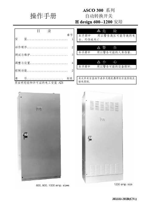
操作手册ASCO 300 系列 自动转换开关H design 600--1200安培目 录 章节 安 装........................... 1 动作顺序........................... 2 测试与维护......................... 3 调整与设置......................... 4 控制功能........................... 5 索 引........................ 封底 须由有经验和许可证的电工安装ATS本手册中危险用以警告高压可能导致的电击、灼伤或死亡。
本手册中警告用以警告可能的人身伤害。
本手册中小心用以警告可能的设备损坏。
有关所有安装细节请参见随机携带的安装图纸及接线图纸。
铭 牌 转换开关铭牌包含每一台ASCO 300系列ATS的参数。
只能在铭牌所示的极限值范围内使用ATS。
目录号标识 典型的目录号如下所示,其中包括各个单元的解释。
例中所示:4极、600安、480伏、I类外箱的ASCO 300系列ATS目录号。
中性线B-转换C-叠加空白-固定相线极数2-单相3-三相电 流60080010001200控制器1-标准1X-带有附件外 箱C-I类F-3R类G-4类*L-12类*空白-无外箱中性线连接电源连接转换开关端子排TB,发电机启动端子及状态接点电源连接薄膜操作面板控制器*只对600-1000安培有效中性线连接ASCO 300系列自动转换开关(ATS)符合UL1008有关ATS的标准。
ASCO 300系列自动转换开关同样符合CSA C22.2第178条有关自动转换开关的标准。
所有控制功能均为UL认可部件,来保证ASCO自动转换开关符合OSHA安全需求,并被电气核查员接受。
ASCO 300系列自动转换开关适用于应急和备用电源系统。
它们符合NEC Article 700 和 UL 1008有关应急系统规定的条件。
kj312数字电流表使用说明
kj312数字电流表使用说明
数字电流表是一种用来测量电流大小的仪器。
以下是对kj312型数字电流表的使用说明:
1.先将电流表的开关调至OFF状态,确保电流表的指针指向0位。
2.确保被测试电路的电源已经关闭,然后将电流表与电路相连。
连接时应将电流表的正极与电路的正极连接,负极与负极连接。
3.将电流表的开关调至ON状态,此时电流表开始工作。
4.当电流流经电流表时,电流表的数字显示屏上会显示电流的数值。
5.读取电流值时,需要注意显示屏上的小数点位置。
根据所需的精确度,将小数点右移或左移相应位数,得到最终的电流值。
6.测量完毕后,将电流表的开关调至OFF状态,断开与电路的连接。
注意事项:
-保持电流表与电路之间的连接良好,并确保连接处无松动。
-在测试电路时,确保电路中的电流不会超过电流表的额定量程,以避免电流过大损坏电流表。
-在使用电流表时,要避免严重的震动和高温环境,以免对电流表的准确度造成影响。
-定期检查和校准电流表,以保持其准确度和可靠性。
EK312A.操作手册

E K312A.操作手册.160825.1(总7页)本页仅作为文档封面,使用时可以删除This document is for reference only-rar21year.MarchEK312.安装使用手册-----2016.08.251概述EK312A是得麦科技开发的1款电子膨胀阀控制器,采用过热度控制膨胀阀开度。
驱动器采用恒流驱动。
可控制ALCO、DANFOSS、SPORLAN、Carel等各种恒流驱动的电子膨胀阀。
EK312A既可与得麦科技的螺杆机控制器联机使用,也可单独使用(与其他厂家控制器组成控制系统)。
1.1EK312A外观图1.2 EK312A外形尺寸图31.3 EK312A 电气连接示意图EK312A电气连接示意图B-GA++-G TI DO W3W2W4AI +24G DI Com ComW1MotorB-GND A+ONOFF1234ON OFF1234O NO F FSW2JP2JP1JP3JP4JP5SW1VCCIout SW1地址1234OFF OFF 1ON OFF 2OFF ON 3ON ON4N LAC220VO N O FFSW212345V 10V举例1:12345123412312345612JP2-5设置为4-20mA输入O N O F FSW21234C V 5V 10V 举例2:JP2-5设置为0-10V输入O N O F FSW21234C V 5V 10V电子膨胀阀接线说明:ALCO膨胀阀:W4:白色W3:黑色W2:棕色W1:蓝色Danfoss膨胀阀:W4:黑色W3:白色W2:绿色W1:红色SPORLAN膨胀阀:W4:白色W3:黑色W2:绿色W1:红色Carel膨胀阀:W4:黄色W3:白色W2:棕色W1:绿色地址拔码说明:模拟输入拔码说明:报警输出启停开关电子膨胀阀24V电源输入压力传感器温度传感器通讯线运行故障通讯确认向上向下C V 0|10V0|5V 电压型电流型使用按键显示板备用注1:压力传感器接线:注2:压力传感器接线处,板内供电是24V ,如果传感器不是24V 供电,则要外接电源,之后将电源的负极接到板上的地(JP2-4)即可。
泰勒螺柱焊接系统V-1B 1 i12拉弧控制器操作说明书

泰勒螺柱焊接系统有限公司i12拉弧控制器操作说明书(1C版)目录页码内容3 重要信息5 重要安全信息7 螺柱焊接简介8 外部特征说明11 设置与焊接15 焊接时间和电流设置16 目视焊接检查17 焊接测试20 焊接技术23 部件列表 & 分解图31 电路图32 配件33 欧盟标准证书安装设备前,请仔细阅读本说明书。
请严格遵守本安全操作说明书。
由于电力要求及在正常使用过程中磁辐射的缘故,本设备必须在工业环境中使用设备操作电压为交流电压未切断主电源前,不得拆卸焊机外壳任一部件不要妨碍下方、前端或后端的控制板通风孔以免导致机器在操作过程中过热不要用焊接电源用于管道软化。
本设备已根据严禁用任何液体清洗电气部件,因那样做会使其渗透到电气系统中。
安装必须按照本说明书第当地的安全规程。
1 2 3 45 6 7 8 9 101 2 3 45 671 2 3 4保存从电流开始,通过旋转控制旋钮设置所需的参数值,然后按下控制旋钮锁定参数并移至下一个屏幕(时间,气体)。
最后一个屏幕保存,是指导您将已设置的参数保存到控制器的20个可用存储位置之一中。
通过旋转控制旋钮选择位置(1 - 20)并通过按下控制旋钮来完成保存,然后控制旋钮将返回到正常操作模式屏幕,该屏幕现在将显示您设置的参数。
如果您已将参数保存在一个或多个存储位置中,也许可能您希1. 准备焊枪2. 放置焊抢3. 触发。
提升&维弧4. 主弧&熔化5. 电弧停止,焊枪插入6. 焊接完成. 撤回最后,轻轻敲击直到它打碎并目视检查焊缝,取下瓷环。
有关焊接螺柱的检查,请参见“目视焊接检查和焊接测试”部分。
过热,导致焊接后螺柱根部长度太短,焊脚过宽且不规则,瓷页),对准调整使 ✓✗✗✗✗✗2. 非破坏试验通常最适用的方法是通过测试带螺纹螺柱的焊缝但不破坏螺柱来检测焊接强度,即安全实验。
这种实验是通过使用扭力扳手来完成。
下面及下页表格可能会很有用。
然而,必须说明的是:∙公式 & 数据仅供参考。
点焊机操作说明

半自动单点电池点焊机操作说明书(电气)OPERATION INSTRUCTIONS!使用前先详细阅读操作说明书或者在有专业技术人员指导下进行操作。
目录一安全防范安装安装点附近不要堆放易燃品。
否则,可能引起火灾。
搬运时一定要抓紧支撑部分。
否则,可能有跌倒损坏危险。
请防止外部异物进入到设备内部。
否则,可能引起短路。
请确保接地良好。
否则,可能引起电击或火灾。
布线必须由合格的电气专业人员作业。
否则,可能引起电击或火灾。
请确保安装空间有良好的通风条件,避免运行环境中有灰尘、腐蚀气体、易燃气体等。
避免安装空间有震动,不牢固。
否则,可能引起短路或损坏。
请确保电压、气源满足以下条件:电源1Φ+N AC220V,50/60Hz,3kW气源~操作断开输入电源超过10 分钟后,再进行维护和检查。
否则,有电击危险。
请确保由合格电气操作人员在经授权后进行维护、检查和更换零件。
否则有电击危险。
不要用湿手操作。
否则,有电击危险。
请确保接地良好。
否则,可能引起电击或火灾。
通电状态下不能接触设备内部配件。
否则,可能引起电击。
发热组件温度非常高,请不要触及。
否则,有烧伤的危险。
二安装使用条件安装条件使用环境三操作说明系统上电1)确认机台电源线、气源(空压机)电源线及米亚基焊接主机电源线已正确连接;2)确认机台断路器处于接通状态,且气源开关和米亚基焊接主机的电源开关处于ON状态;3)按下操作面板箱上的电源开关,并确认红色电源指示灯点亮;4)待操作面板箱上的触摸屏显示如图所示的开机画面时,表示系统已上电完成。
系统初始化系统上电完成后,触摸屏会显示如图所示的开机画面。
此时会显示机台当前状态为“等待初始化”状态,长按屏幕左下方的“一键复位”按钮1秒,待“一键复位”按钮显示为绿色黄色“复位中”时,机台开始初始化,即复位伺服电机位置及扫描焊接主机是否正常。
图系统开机画面系统初始化时,若没有接通焊接机电源,则会弹出如图所示的米亚基初始化失败提示窗,如果是正常作业,则需要确认米亚基焊接主机是否已经正常供电;如果只是进行对位测试,则只需长按窗口右下方的“跳过自检”按钮直至窗口自动关闭为止即可。
欧科水冷模块冷水机组EK325控制器使用手册

39 系统 2 制冷剂泄露 40 TH1 故障 41 TH2 故障 42 TH3 故障 43 TH4 故障 44 TH5 故障 45 TH6 故障
22 传感器故障 24 系统 2 高压故障 25 进出水温度过低 26 水系统电加热过载 27 环境温度过高/过低 29 系统 1 过热度过小 32 系统 1 回气温度过高 33 系统 1 排气温度过高 34 系统 2 回气温度过高
设置 4 个,在“机组号”上方有指示),按“确定”键选定某个定时,进入定 时开或关的选择。
③ 按“▲”或“▼”键选择“定时开”或“定时关”,按“确定”键选定当前这
个定时是开还是关,进入定时时间的选择,此时显示器上显示“定时设置”和 “时钟设置”,并且时间闪烁。
④ 再按“▲”键修改小时,按“▼”键修改分钟,设置好时间后按“确定”键
46 TH7 故障 47 TH8 故障 48 TH9 故障 49 TH10 故障 50 TH11 故障 51 TH12 故障 52 系统 2 低压故障 53 系统 1 低压故障
35 系统 2 排气温度过高
如果机组设置有二通阀联锁功能,机组处于二通阀联锁关机状态时,线控器显示
“SA”。
7
EK325 使用手册
水冷模块热回收(空调优先) 制冷→制冷+热水
3 机组设置
·按“机组”键机组号闪烁,按“▲”或“▼”键选择所需机组号,然后按“确
定”键后选中机组可以进行步骤 4、5。
4 参数查询 · 风冷冷水机组:使用本控制器能查询当前机组的工作状态及参数(有哪几台压 缩机在工作、进水设置温度、进水温度、出水设置温度、出水温度、定时设置、 制冷防冻温度、冬季防冻温度、除霜温度等,其中除霜间隔和除霜显示分别表示
EK325 使用手册
爱普生投影机EK-103X使用手册说明书
使用手冊EK-103X2注意:- 本手冊中的螢幕選單和圖片可能與產品有細微的差異。
- 本手冊的內容如有變動,恕不另行通知。
特點安全防護功能安全防護功能可協助確保投影機的安全。
透過按鍵銷定功能可以鎖定控制面板或遙控器的操作。
密碼鎖定功能可以防止未授權的人直接操作投影機。
自動調整功能您只需要按下遙控器的Auto鍵,就會開始執行"輸入源搜尋"和"自動電腦調整"的自動調整功能。
配色板功能當在有色的牆壁上進行投影時,您可以在預設的四種色版設定中,選取與牆面色彩最相近的一款,進而獲取與在白色螢幕上投影相似的效果。
電源控制電源控制功能可以減少耗電量並能延長燈泡的使用壽命。
Closed CaptionClosed Caption 是以字幕形式在螢幕上顯示節目聲音或其它訊息。
您可以打開此功能並轉換頻道以使用此效果。
本多媒體投影機的設計採用眾多先進技術,具有攜帶方便、經久耐用和使用簡單等特點。
本投影機具有內置多媒體功能,並且採用矩陣液晶顯示(LCD)技術。
目錄特點 (2)目錄 (3)安全介紹 (4)安全指南 (5)空氣流通 (6)移動投影機 (6)正確放置投影機 (6)規範 (7)配件 (8)各部分名稱和功能 (9)前面 (9)背面 (9)底部 (9)端子板 (10)控制面板和LED指示燈 (11)遙控器 (12)安裝遙控器電池 (13)遙控器操作距離 (13)安裝 (14)放置投影機 (14)調整腳 (14)連接至電腦(數位和類比RGB) (15)連接至視頻設備(視頻,S視頻) (16)連接電源線 (17)基本操作 (18)開啟投影機 (18)關閉投影機 (19)變焦和聚焦調節 (20)自動設定功能 (20)梯形校正 (20)遙控器操作 (21)輸入源選擇 (23)如何操作螢幕選單 (24)選單欄 (25)顯示選單 (26)自動同步 (26)相位 (26)水平位置 (26)垂直位置 (26)水平尺寸 (26)影像大小 (27)投影方式 (27)選單位置 (28)顯示背景 (28)系統.......................................28色彩調整. (30)影像模式 (30)色彩調整(電腦) (31)色彩調整 (視頻,S視頻,色差分量) (32)選項 (33)自動開機 (33)待機狀態 (33)高原模式 (34)燈泡模式 (34)快速關機 (34)Closed Caption (35)按鍵鎖定 (35)HDMI 設置 (36)擴展選單 (37)語言 (37)自動設定 (37)梯形校正 (38)Logo (39)安全 (40)電源控制 (41)濾網計時器 (41)測試圖形 (42)出廠設置 (42)燈泡使用時間 (42)信息 (43)維護和清潔 (44)警示指示燈 (44)清潔防塵網 (45)重設防塵網計數 (45)清潔投影機鏡頭 (46)燈泡更換 (47)更換燈泡型號 (48)附錄 (49)故障檢測 (49)選單 (51)指示燈和投影機狀態 (54)兼容電腦規格 (55)技術規格 (56)端子配置 (57)產品中有毒有害物質和元素及含量標注 (58)尺寸 (58)密碼備忘錄 (59)3致用户在安裝和操作本投影機前,請完整閱讀本手冊。
EK312A.操作手册.150824
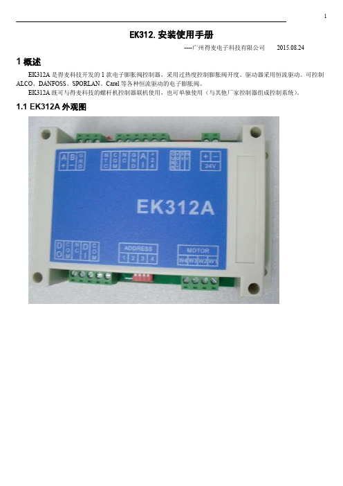
EK312.安装使用手册----广州得麦电子科技有限公司2015.08.241 概述EK312A是得麦科技开发的1款电子膨胀阀控制器,采用过热度控制膨胀阀开度。
驱动器采用恒流驱动。
可控制ALCO、DANFOSS、SPORLAN、Carel等各种恒流驱动的电子膨胀阀。
EK312A既可与得麦科技的螺杆机控制器联机使用,也可单独使用(与其他厂家控制器组成控制系统)。
1.1 EK312A外观图1.2 EK312A 外形尺寸图1.3 EK312A 电气连接示意图EK312A电气连接示意图B-GA++-G TI DO W3W2W4AI +24G DI Com Com W1MotorB-GND A+ON OFF 1234ON OFF 1234O NO F FSW2JP2JP1JP3JP4JP5SW1VCCIout SW1地址1234OFF OFF 1ON OFF 2OFF ON 3ON ON 4N LAC220V O N O F FSW212345V 10V 举例1:12345123412312345612JP2-5设置为4-20mA输入O NO F FSW21234C V 5V 10V 举例2:JP2-5设置为0-10V输入O N O F FSW21234C V 5V 10V电子膨胀阀接线说明:ALCO膨胀阀:W4:白色W3:黑色W2:棕色W1:蓝色Danfoss膨胀阀:W4:黑色W3:白色W2:绿色W1:红色SPORLAN膨胀阀:W4:白色W3:黑色W2:红色W1:绿色Carel膨胀阀:W4:黄色W3:白色W2:棕色W1:绿色地址拔码说明:模拟输入拔码说明:报警输出启停开关电子膨胀阀24V电源输入压力传感器温度传感器通讯线运行故障通讯确认向上向下C V 0|10V0|5V 电压型电流型使用按键显示板备用2 控制逻辑EK312A可选择“吸气过热度”、“手动”、“模拟量控制”3种控制方式(由参数“P33膨胀阀控制方式”设置,默认吸气过热度控制)。
迪亚尔brand电子厨Sink 50N 32使用指南与维护指南说明书

Instructions for use and maintenance of gas, gas-electric and electric cookers. Series:32-Thank you for choosing one of our quality products, capable of giving you the very best service. To make full use of its perfor-mance features, read the parts of this manual which refer to your appliance carefully. The Manufacturer declines all responsibility for injury or damage caused by poor installation or improper use of the appliance.-To ensure its appliances are always at the state of the art, and/or to allow constant improvement in quality, the manufacturer reserves the right to make modifications without notice, although without creating difficulties for users.-When ordering spare parts, inform your dealer of the model number and serial number punched on your appliance’s nameplate, visible inside the warming compartment or on the back of the cooker.-APPLIANCE COMPLYING WITH THE FOLLOWING DIRECTIVES:- EEC 90/396- EEC 73/23 and 93/88-EEC 89/336 (radio-frequency inter-ference)- EEC 89/109 (contact with foods)FOREWORD-Refer only to the headings and sections covering accessories actually installed on your cooker.Technical data andspecifications.............................33Installation..........................34 - 36Ventilation......................................34Positioning.....................................34Gas connection .............................34Adapting to different typesof gas ............................................35Replacing the injectors ..................35Regulating the air ..........................35Minimum setting ............................35Electrical connection .....................36Safety device (36)For the user....................... 37 - 40Ventilation......................................37Igniting the burners....................... 37Igniting the gas oven .................... 37Igniting the gas grill .......................37Safety device.................................37Using the gas hob .........................37Using the electric hot-plates ..........37Using the gas oven........................38Using the gas or electric grill ........38Using the conventionalelectric oven ..................................38Using the conventionalmultifunction electric oven .............39Oven with thermostat ....................39Warming compartment ..................39Advice and precautions.. (39)Figures .............................. 41 - 43ELECTRIC HOTPLATESø 1451,0 kW - Normal hotplate1,5 kW - Rapid hotplateø 1801,5 kW - Normal hotplate2,0 kW - Rapid hotplate ELECTRIC OVEN POWEROven: (1,1kW bottom0,7kW top element)2,2 kW Grill:2,0 kW Cat.: see nameplate on cover; Class 1 or 2.1 Type “X” cookersEQUIPMENTAll models are equipped with safety device for oven and grill burners.Depending on the models, cooker may also have:-Oven thermostat (or tap)-Electric oven lighting-Grill burner or element-One or more electric hotplatesFor the LAYOUT OF HOB BURNERS see the models illustrated in figure 1 at the back of this manual.For the ELECTRIC WIRING DIAGRAM see figure 2 at the back of this manual.The electrical power is stated on the name-plate visible inside the warming compartment (if present) or on the back of the cooker.A copy of the nameplate is glued to the coverof this manual (for gas or gas-electric prod-ucts only).33INSTALLATIONThe appliance must be installed by qualified staff working in accordance with the regula-tions in force.Before installing, ensure that the appliance is correctly preset for the local distribution conditions (gas type and pressure).The presettings of this appliance are indi-cated on the nameplate shown on the cover. This appliance is not connected to a flue gas extractor device. It must be installed and connected in accordance with the regulations in force.This appliance may only be installed and may only operate in rooms permanently ventilated in accordance with national regulations in force.VENTILATIONThe rooms in which gas appliances are in-stalled must be well ventilated in order to al-low correct gas combustion and ventilation. The air flow necessary for combustion is at least 2 m3/h for each kW of rated power. POSITIONINGRemove the packaging accessories, includ-ing the films covering the chrome-plated and stainless steel parts, from the cooker. Position the cooker in a dry, convenient and draft-free place. Keep at an appropriate dis-tance from walls which may be damaged by heat (wood, linoleum, paper, etc.).The cooker may be free-standing (class 1) or between two units (in class 2 st 2-1) the sides of which must withstand a tempera-ture of 100°C and which must not be higher than the working table.CONNECTING TO THE GAS SUPPLY Before connecting the cooker, check that it is preset for the gas to be used. Otherwise, make the conversion as described in the section headed “Adapting to different gas types”. The connection is on the right; if the pipe has to pass behind the cooker, it must be kept low down where the temperature isabout 50°C.-Rigid connection (see fig. 3 A + B)The connection to the mains gas supplymay be made using a rigid metal pipe orwith a metal hose. Remove the hose con-nector (if already fitted) and screw the rigidunion onto the threaded connection of thegas train (see fig. 3A). The union for rigidconnection may already be fitted on the gastrain, or may be amongst the cooker ac-cessories. Otherwise, it can be obtainedfrom your dealer.If national regulations permit, a metal hosecomplying with the national standards canbe screwed directly onto the threaded con-nection of the gas train, fitting a seal (seefig. 3B). However, users are strongly rec-ommended always to fit the rigid union.-Connection using a rubber hose (see fig.3C). (For butane/propane gas only).Connect a rubber hose carrying the con-formity mark currently in force to the hoseconnector. The hose must be replaced atthe date indicated at the latest, and mustbe secured at both ends using stand-ard hose clamps. It must be absolutelyaccessible to allow its condition to bechecked along its entire length.CAUTION:-Use of the hose connector is only per-mitted for free-standing installation. Ifthe appliance is installed between twoclass 2 st. 2-1 unions, the rigid union isthe only form of connection permitted.IMPORTANT:-After installation, check that the connec-tions are airtight.-For operation with butane/propane, checkthat the gas pressure is as indicated on thenameplate.-Use only standard rubber hoses. For LPG,use a hose which complies with the nationalregulations in force.-Avoid sharp bends in the pipe and keep itwell way from hot surfaces.References to the regulations covering the gas connection to the appliance: ISO 7-1.34ADAPTING TO DIFFERENT TYPES OF GASIf the cooker is not already preset to operate with the type of gas available, it must be con-verted. Proceed as follows:-Replace the injectors (see table on page 33);-regulate the primary air flow;-regulate the minimum settings.N.B.: every time you change the type of gas, indicate the new type of gas on the serial number label.REPLACING THE HOB BURNER INJEC-TORS (fig. 4)-Remove the lid of the cooker by lifting it off its supports;-remove the grids, burner caps and burn-ers, lifting them off;-unscrew the 2 screws (above) or nuts (be-low) at the back which secure the work top, and pull it out forward.-remove the mixer pipes and replace the injectors using a 7 mm socket wrench. REPLACING THE OVEN BURNER INJEC-TOR (Fig. 5)-Loosen the screw which secures the bot-tom of the oven;-remove the oven bottom (pulling it forward); -remove the oven burner, after taking out the screw which secures it;-replace the injector using a 7 mm socket wrench.REPLACING THE GRILL BURNER INJEC-TOR (Fig. 6)-Remove the burner after taking out the two screws which secure it;-replace the injector using a 7 mm socket wrench.IMPORTANT:-Never over-tighten the injectors;-after replacing, check that all the injectors are airtight.Burner G20 20mbar G30 28-30mbarG31 37mbar Auxiliary3 4Semi-rapid3 3Rapid4 6Oven- -Grill3 8REGULATING THE BURNER AIRRefer to the table below (indicative values) for regulation of the gap H in mm (fig. 4 for the hob, fig. 6 for the grill).Check operation of the burner:-Ignite the burner at maximum flame;-the tongue of the flame must be clear andwith no yellow tip, and must adhere closelyto the burner. If too much air is supplied,the flame detaches from the burner andmay be dangerous. If the air supply is in-sufficient, the flame has a yellow tip andsoot may form.SETTING HOB BURNER MINIMUM LEV-ELSIf the cooker is to work on bottled gas (bu-tane/propane), the tap by-pass must be screwed right down.The cooker may be equipped with type A taps, with by-pass inside (accessed by in-serting a small screwdriver into the rod) or type B taps, with by-pass on the outside on the right (accessed directly). See figure 7.If the cooker is to work on natural gas, pro-ceed as follows for both types of tap:-Ignite the burner at maximum flame;-pull off the knob, without using a leveragainst the control panel, which might bedamaged;-access the by-pass with a small screwdriverand back off by about 3 turns (turning thescrewdriver anti-clockwise);-turn the tap rod anti-clockwise again until itstops: the burner will be at maximum flame;-screw the by-pass slowly back in, withoutpushing the screw-driver, until the flame hasapparently shrunk to 1/4 of the maximumsize, checking that it is sufficiently stable35even in quite strong draughts.SETTING OVEN BURNER MINIMUM LEV-ELSIf the cooker is to work on bottled gas (bu-tane/propane), the thermostat by-pass must be screwed right down.If the cooker is to work on natural gas, pro-ceed as follows:-Remove the oven bottom (loosen the screw to remove the bottom);-ignite the oven burner, turning the knob pointer to the maximum setting;-shut the oven door;-access the thermostat or tap by-pass (see fig. 8);-back off the thermostat by-pass by about 3 turns;-after 5 or 6 minutes, turn the knob pointer to the minimum setting;-slowly re-tighten the by-pass, watching the flame decrease in size through the window in the closed oven door until the tongue of the flame is about 4 mm long. Never keep the flame too low. It must be stable even when the oven door is opened or closed quickly;-turn off the burner and replace the oven bottom.CONNECTING TO THE ELECTRICAL MAINSBefore making the connection, check that: -the mains voltage is as indicated on the nameplate;-the earth connection is in good working or-der.If the socket is not easily accessible, the in-stallation engineer must provide a switch with a contact breaking gap of 3 mm or more.If the appliance power lead is not fitted with a plug, use an approved standard type, re-membering that:-the green-yellow wire must be used for the earth connection;-the blue wire is the neutral;-the brown wire is live;-the lead must never touch hot surfaces overabout 75 degrees C;-replacement leads must be of type H05RR-F or H05V2V2-F of suitable size (see dia-grams in fig. 2).-if the appliance is supplied without lead,using type H05RR-F or H05V2V2-F cableof suitable size (see diagrams in fig. 2).IMPORTANT: the manufacturer declines all liability for damage due to failure to comply with the regulations and standards in force.Check that the appliance is correctly con-nected to the earth (see diagrams in fig. 2 at the back of the manual).THE SAFETY DEVICEThe correct gap between the end of the ther-mocouple sensor and the burner is shown in figures 5 and 6.To check that the valve is working properly, proceed as follows:-ignite the burner and leave it to work forabout 3 minutes;-turn off the burner by returning the knob tooff position (-turn the knob pointer to the "on" position;-release the knob in this position and movea burning match towards the burner; ITMUST NOT IGNITE.Time needed to excite the magnet during ignition: 10 seconds approx.Automatic tripping time, after flame has been turned off: not more than 60 seconds for oven and grill burners.IMPORTANT-Before doing any work inside the cooker, dis-connect the mains plug and shut the gas tap.-Never use matches to check the gas cir-cuit for leaks. If a specific control device isnot available, foam or very soapy water canbe used.-When re-closing the hob, check that theelectrical wires of the spark plugs (ifpresent) are not close to the injectors, sothat they cannot run across them.36HOW TO USE THE COOKER VENTILATIONAll gas cooking appliances produce heat and moisture in the rooms where they are in-stalled. Take care to ensure that the kitchen is well ventilated; keep the ventilation open-ings unobstructed or install an extractor hood with fan.In case of intensive or prolonged use, addi-tional ventilation may be required; open a window, or increase the extractor fan power. IGNITING THE HOB BURNERS-Press the knob and turn it anti-clockwise-at the same time, move a burning match towards the burner head;-to reduce the flame, turn the knob further in the same direction until its pointer issition).IGNITING THE OVEN BURNER-Open the oven door;-press the knob and turn it anti-clockwise to the maximum flame position;-move a burning match towards the hole in the centre of the oven bottom and press the knob right down (see fig. 9);-check that the burner has ignited, looking through the hole in the centre of the bot-tom, keeping the knob pressed all the time; -after about 10 seconds, release the knob and check that the burner remains on. Oth-erwise, repeat the operation.IGNITING THE GRILL BURNER (GAS GRILLS)-Fit the control knob guard as shown in fig. 12;-press the oven knob and turn it to the right until it reaches the stop;-move a burning match towards the perfo-rated burner pipe and press the knob right down (see fig. 10);-check that the burner has ignited, keepingthe knob pressed down;-after about 10 seconds, release the knoband check that the burner remains on. Oth-erwise, repeat the operation.IMPORTANT-Difficulty in igniting burners is normal if thecooker has been out of use for some time.The air accumulated in the pipes will beexpelled in a few seconds;-Never allow too much unburnt gas to flowfrom the burners. If ignition is not achievedwithin a relatively short time, repeat the pro-cedure after returning the knob to the offposition (-time, a smell may be noticed and smokemay come out of the oven. This is becauseof the surface treatment and oily residueson the burners.SAFETY DEVICEBurners equipped with this device have the advantage that they are protected if they accidentally go out. If this occurs, the supply of gas to the burner concerned is automati-cally cut off, preventing the hazards deriving from a leak of unburnt gas. The gas supply must be cut off within no more than 60 sec-onds for the oven and grill burners.HOW TO USE THE HOB BURNERSUse pans of diameter suitable for the burner type. The flames must not project beyond the base of the pan. Recommended sizes: -for auxiliary burners = pans of at least 8 cm -for semi-rapid burners = pans of at least 14 cm -for rapid burners = pans of at least 22 cm.N.B.: Never keep the knob at settings be-off position .FOR COOKERS EQUIPPED WITH ELEC-TRIC HOTPLATESThe different heat settings are obtained as follows:37- 1 = minimum setting for all hotplates;- 6 = maximum setting for normal and rapid hotplates (with red disc);- 0 = off.Pans must never be smaller in diameter than the hotplates and their bottoms must be as flat as possible (see fig. 11). IMPORTANT:-Never leave hotplates on without pans, except when first used; leave for about 10 minutes to dry oil or moisture residues;-if the hotplate is to be out of use for a long time, apply a little grease to its painted surface; -do not allow spills to burn onto the hotplate, requiring the use of abrasive cleaners. HOW TO USE THE GAS OVEN-After igniting the burner, leave the oven to heat up for about 10 minutes;-place the food for cooking in an ordinary oven dish and place it on the chrome-plated shelf; -place the food in the oven, using the shelf on the third pair of runners whenever possi-ble, and turn the knob pointer to the desired setting;-cooking can be observed through the window in the door with the oven light on. This will avoid opening and closing the door frequently, unless oil or fat has to be added to the dish. IMPORTANT: never place foods directly on the drip tray for cooking; it is there only to collect any drips of fat during grilling.N.B.: For cookers without thermostat:-270 degrees C-150 degrees C-All other temperatures between 150 and 270 degrees C are obtained approximately by positioning the knob between the maxi-mum and minimum settings.Never leave the knob in positions between theHOW TO USE THE GAS OR ELECTRIC GRILL-fit the knob guard (see fig. 12);-ignite the burner and wait a few minutes toallow it to warm up, or switch on the heat-ing element;-place the foods on the chrome-plated shelf;-insert on the highest runner;-insert the drip tray on the bottom runner;-gently close the oven door, resting it againstthe knob guard;-after a few minutes, turn the food to exposethe other side to the infrared radiation (thecooking time depends on the type of foodand personal taste).N.B.: the first time the grill is used smoke will come out of the oven. Before inserting foods for cooking, wait until any oil residues on the burner have completely burnt away.The grill must only be used at its full rated heat.IMPORTANT: accessible parts may be hot when the grill is in use! Keep children well away.The grill element in the top of the oven is switched on by turning the thermostat knob clockwise to the grill symbol on the control panel.The red light will come on to show the ele-ment is in operation.The table below will serve as a guide; bear-ing in mind that cooking times and tempera-tures may vary depending on the type and amount of foods cooked and personal taste.Food to be Time (minutes)grilled1st side2nd sideThin pieces of meat 6 4Fairly thick pieces ofmeat 8 5Thin fish or fishwithout scale10 8Fairly thick fish1512Sausages1210Toasted sandwiches 5 2Small poultry2015CONVENTIONAL ELECTRIC OVEN-The oven shelf is designed to take normaloven dishes for cooking sweets or roasts,3839-The oven shelf is designed to take normal oven dishes for cooking sweets or roasts,or is used without a pan for cooking foods under the grill.-The drip tray is only there to collect any juice from foods and must never be used as a cooking surface.OVENS WITH THERMOSTATIf cooking temperatures are not as set, call in an engineer to check the thermostat.WARMING COMPARTMENTTo open the warming compartment, open the flap door with one hand (see figure 13).To close the warming compartment, simply press the flap door back into place.GENERAL PRECAUTIONS-Always disconnect the power supply before any work inside the oven or where live parts may be accessed.-Never use the warming compartment for storing inflammable liquids or items which do not withstand heat, such as wood, pa-per, aerosol cans, matches, etc.-Make frequent checks on the rubber con-nection hose, ensuring that it is well away from hot surfaces, that there are no sharp bends or kinks, and that it is in good condi-tion. The hose must be replaced at the lat-est at the indicated date and must be se-cured at both ends using a standard hose clamp.-If taps become stiff to operate over time,contact the After-Sales service.-Wash enamelled or chrome-plated parts with soapy lukewarm water or non-abrasive detergents. A metal brush may be used to remove deposits from hob burners and flame caps. Dry thoroughly.-Never use abrasives to clean enamelled or chrome-plated parts.-Do not use too much water when washing the hob. Take care that no water or other substances enter the burner housing holes,as this may be dangerous.or is used without a pan for cooking foods under the grill.-The drip tray is only there to collect any juice from foods and must never be used as a cooking surface.There is a single control knob for the oven or grill.Starting from the 0 (off) position, the knob can be turned clockwise to the following settings:--The spark plugs for electric ignition mustbe kept clean and dry; always check after use, particularly if there have been drips or overflows from pans.-Never close glass lids until the hob burn-ers or hotplates have cooled completely; it might shatter or crack.-Never knock enamelled parts or ignition spark plugs (where present).-The main or wall gas tap should be turnedoff when the cooker is not in use.-Never lift the cooker by taking hold of the oven door handle.No liability is accepted for injury or damage caused by poor installation or improper useof the cooker.In case of malfunctions, particularly gas leaks or short-circuits, contact your en-gineer without delay.404142587634mm 2 - 4HBA43121011ED. 09.02.1999334813B1/44。
CLASSIC III 线性电焊机操作手册说明书
CLASSIC ®III & CLASSIC ®III DFor Machines with Code Numbers 10033, 10061, 10072 or 10156Supersedes IM482IM529-AOctober, 1999Safety Depends on YouLincoln arc welding equipment is designed and built with safety in mind. However, your overall safety can be increased by proper installation ... and thoughtful operation on your part.DO NOT INSTALL,OPERATE OR REPAIR THIS EQUIPMENT WITHOUT READING THIS MANUAL AND THE SAFETY PRECAUTIONS CONTAINED THROUGHOUT.And, most importantly, thinkbefore you act and be careful.Mar ‘95Mar. ‘93for selecting a QUALITY product by Lincoln Electric. We want you to take pride in operating this Lincoln Electric C ompany product ••• as much pride as we have in bringing this product to you!Read this Operators Manual completely before attempting to use this equipment. Save this manual and keep it handy for quick reference. Pay particular attention to the safety instructions we have provided for your protection.The level of seriousness to be applied to each is explained below:vvviTECHNICAL SPECIFICATIONS – CLASSIC III AND IIID Machine*Based on a 10 min. period.@Meets Canadian StandardsProduct Name Description Horsepower OperatingSpeedsDisplacement Ignition CapacitiesClassic III Classic III D4 Cylinder4 CycleWater-CooledGasoline EngineCast Iron Cylinder,Block/Crankcase4 Cylinder4 CycleWater-CooledDiesel EngineCast Iron Cylinder,Block/Crankcase45 HP@ 1700 RPM38.9 HP@ 1700 RPMFull Load:1725 RPMHigh Idle:1800 RPMLow Idle:1350 RPM164.7 Cu In(2.7 ltrs)Distributor TypeElectronicDieselFuel:15 Gals (57 Ltrs)Lubricating Oil:7.0 Qts (6.7 Ltrs)Coolant:9.3 Qts (8.8 Ltrs)EngineB AWire Feed Module (K623-1) - Provides constant voltage (C V) output with improved arc stability for Innershield welding. Excellent for MIG welding. Recommended wire feeders are the LN-7, LN-23P and LN-25. (Factory installed on the K1428-3 and K1433-2).NameplatesWhenever routine maintenance is performed on this machine - or at least yearly - inspect all nameplates and labels for legibility. Replace those which are no longer clear. Refer to the parts list for the replace-ment item number.I = Inspect C = Clean R = Replace NOTES:(1)Consult Engine Operators Manual for oil recommendations.(2)Or equivalent.(3)First inspection after 50 hours; every 500 thereafter.(4)Gasoline engine only.(5)Diesel engine only. (Welder Code Numbers 10061 and below)(6)Diesel engine only. (Welder Code Numbers above 10061)(7)Consult Engine Operators Manual for additional maintenance schedule information.5-6-94C S20919-1TROUBLESHOOTINGHave qualified personnel do the troubleshooting work. Turn the engine off before working inside the machine. In some cases, it may be neces-sary to remove safety guards to perform required maintenance. Remove guards only when necessary and replace them when the maintenance requiring their removal is com-plete. Always use the greatest care when work-ing near moving parts.Do not put your hands near the engine cooling blower fan. If a problem cannot be corrected by following the instructions, take the machine to the nearest Lincoln Field Service Shop.------------------------------------------------------------ELECTRIC SHOCK can kill.•Do not touch electrically live parts or electrode with skin or wet clothing.•Insulate yourself from work and ground• Always wear dry insulating gloves.EXHAUST can kill.Use in open, well ventilated areas or vent exhaust outside.------------------------------------------------------------------------MOVING PARTS can injure.•Do not operate with doors open or guards off.• Stop engine before servicing.• Keep away from moving parts.------------------------------------------------------------------------See additional warning information at the front of this operator’s manual------------------------------------------------------------(1)FLASHING THE FIELDS:1.Stop the engine welder and remove the cover from the exciter.2.Turn the “Fine Adjustment Control” (rheostat) to “100” on the dial.ing a 12 volt automotive battery, connect it’s negative terminal to the negative brushholder. Thenegative brushholder is the one nearest to the rotor lamination. See the wiring diagram. With theengine NOT running, touch the positive battery terminal to the positive brushholder. Remove thebattery from the circuit.4.Replace the exciter cover. Start the welder and the generator voltage should build up.ENGINE TROUBLESHOOTING - (TM27 Gasoline Engine Only)**See engine manual.L 9260C L A S S I C I I ID W I R I N G D I A G R A ME : T h i s d i a g r a m i s f o r r e f e r e n c e o n l y . I t m a y n o t b e a c c u r a t e f o r a l l m a c h i n e s c o v e r e d b y t h i s m a n u a l . T h e s p e c i f i c d i a g r a m f o r a p a r t i c u l a r c o d e i s p a s t e d i n s i d e a c h i n e o n o n e o f t h e e n c l o s u r e p a n e l s . I f t h e d i a g r a m i s i l l e g i b l e , w r i t e t o t h e S e r v i c e D e p a r t m e n t f o r a r e p l a c e m e n t . G i v e t h e e q u i p m e n t c o d e n u m b e r ..Now Available...12th EditionThe Procedure Handbook of Arc WeldingWith over 500,000 copies of previous editions published since 1933, the Procedure Handbook is considered by many to be the “Bible” of the arc welding industry.This printing will go fast so don’t delay. Place your order now using the coupon below.The hardbound book contains over 750 pages of welding information, techniques and procedures. Much of this material has never been included in any other book.A must for all welders, supervisors, engineers and designers. Many welding instructors will want to use the book as a reference for all students by taking advantage of the low quantity discount prices which include shipping by 4th class parcel post.$15.00postage paid U.S.A. MainlandHow To Read Shop DrawingsThe book contains the latest information and application data on the American Welding Society Standard Welding Symbols. Detailed discussion tells how engineers and draftsmen use the “short-cut” language of symbols to pass on assembly and welding information to shop personnel.Practical exercises and examples develop the reader’s ability to visualize mechanically drawn objects as they will appear in their assembled form.187 pages with more than 100 illustrations. Size 8-1/2” x 11”Durable, cloth-covered board binding.$4.50postage paid U.S.A. MainlandNew Lessons in Arc WeldingLessons, simply written, cover manipulatory techniques;machine and electrode characteristics; related subjects,such as distortion; and supplemental information on arc welding applications, speeds and costs. Practice materials,exercises, questions and answers are suggested for each lesson.528 pages, well illustrated, 6” x 9” size, bound in simulated,gold embossed leather.$5.00postage paid U.S.A. MainlandNeed Welding Training?The Lincoln Electric C ompany operates the oldest and most respected Arc Welding School in the United States at its corporate headquarters in C leveland, Ohio. Over 100,000stu-dents have graduated. Tuition is low and the training is “hands on”For details write:Lincoln Welding School 22801 St. Clair Ave.Cleveland, Ohio 44117-1199.and ask for bulletin ED-80 or call 216-383-2259 and ask for the Welding School Registrar.Lincoln Welding SchoolBASIC COURSE $700.005 weeks of fundamentalsThere is a 10%discount on all orders of $50.00 or more for shipment at one time to one location.Orders of $50 or less before discount or orders outside of North America must be prepaid with charge, check or money order in U.S. Funds Only.Prices include shipment by 4th Class Book Rate for U.S.A. Mainland Only.Please allow up to 4 weeks for delivery.UPS Shipping for North America Only.All prepaid orders that request UPS shipment please add:$5.00For order value up to $49.99$10.00For order value between $50.00 & $99.99$15.00For order value between $100.00 & $149.00For North America invoiced orders over $50.00 & credit card orders, if UPS is requested, it will be invoiced or charged to you at cost.Outside U.S.A. Mainland order must be prepaid in U.S. Funds. Please add $2.00 per book for surface mail or $15.00 per book for air parcel post shipment.METHOD OF PAYMENT:(Sorry, No C.O.D. Orders)CHECK ONE:Name:_______________________________________________Please Invoice (only if order is over $50.00)Address:_______________________________________________Check or Money Order Enclosed, U.S. Funds only _______________________________________________Credit Card - Telephone:_______________________________________________Signature as it appears on Charge Card:Account No.Exp Date|_|_||_|_|______________________Month YearUSE THIS FORM TO ORDER:Order from:BOOK DIVISION, The Lincoln Electric Company, 22801 St. Clair Avenue, Cleveland, Ohio 44117-1199BOOKS OR FREE INFORMATIVE CATALOGS Telephone: 216-383-2211 or, for fastest service, FAX this completed form to: 216-361-5901.Lincoln Welding School Titles:Price Code QuantityCost(ED-80)New Lessons in Arc Welding $5.00L Seminar Information Procedure Handbook “Twelfth Edition”$15.00PH (ED-45)How to Read Shop Drawings $4.50H Educational Video Information Incentive Management $5.00IM (ED-93) A New Approach to Industrial Economics $5.00NA James F. Lincoln Arc Welding The American Century of John C. Lincoln $5.00AC Foundation Book Information Welding Preheat Calculator $3.00WC-8(JFLF-515)Pipe Welding Charts $4.50ED-89SUB TOTALAdditional Shipping Costs if anyTOTAL COSTJapaneseChineseKoreanArabicREAD AND UNDERSTAND THE MANUFACTURER’S INSTRUCTION FOR THIS EQUIPMENT AND THE CONSUMABLES TO BE USED AND FOLLOW YOUR EMPLOYER’S SAFETY PRACTICES.SE RECOMIENDA LEER Y ENTENDER LAS INSTRUCCIONES DEL FABRICANTE PARA EL USO DE ESTE EQUIPO Y LOS CONSUMIBLES QUE VA A UTILIZAR, SIGA LAS MEDIDAS DE SEGURIDAD DE SU SUPERVISOR.LISEZ ET COMPRENEZ LES INSTRUCTIONS DU FABRICANT EN CE QUI REGARDE CET EQUIPMENT ET LES PRODUITS A ETRE EMPLOYES ET SUIVEZ LES PROCEDURES DE SECURITE DE VOTRE EMPLOYEUR.LESEN SIE UND BEFOLGEN SIE DIE BETRIEBSANLEITUNG DER ANLAGE UND DEN ELEKTRODENEINSATZ DES HER-STELLERS. DIE UNFALLVERHÜTUNGSVORSCHRIFTEN DES ARBEITGEBERS SIND EBENFALLS ZU BEACHTEN.JapaneseChineseKoreanArabicLEIA E COMPREENDA AS INSTRUÇÕES DO FABRICANTE PARA ESTE EQUIPAMENTO E AS PARTES DE USO, E SIGA AS PRÁTICAS DE SEGURANÇA DO EMPREGADOR.• Sales and Service through Subsidiaries and Distributors Worldwide •Cleveland, Ohio 44117-1199 U.S.A. TEL: 216.481.8100 FAX: 216.486.1751 WEB SITE: 。
kj312数字电流表使用说明
kj312数字电流表使用说明
1.接线:将测量电流的引线分别插入数字电流表的COM和mA端口,
确保连接牢固。
2.功率开关:在使用电流表之前,确保其功率开关处于关闭状态,以
免影响测量结果。
3.测量范围选择:根据待测电流的预估范围,选择合适的量程。
通常,数字电流表提供多个测量范围,如200mA、2A、10A等。
选择过大的量程
可能导致读数不准确,选择过小的量程则可能导致量程超限。
4.正负极性:在连接电流电路之前,确认电流的流动方向,确保选择
适当的正负极性。
通常,数字电流表提供AC和DC两种测量模式,根据待
测电流的类型选择相应模式。
5.测量:打开功率开关,让电流通过数字电流表。
此时,数字电流表
将显示测量电流的数值。
保持电路条件稳定,以获得准确的测量结果。
测
量完成后,关闭功率开关,断开电流电路。
6.单位转换:根据需要,可以将数字电流表的显示单位从毫安(mA)
转换为其他单位(如安培A)。
具体的操作方式请参考数字电流表的使用
说明书。
7.注意事项:遵守安全规范,确保使用合适的保护措施,以免发生电
击或其他意外伤害。
在测量高电流时,应注意防止过热和短路。
以上是数字电流表的基本使用说明,具体的操作和注意事项请参考您
所使用的具体型号的使用说明书。
EKD316 EKC312 Manual

电S源up电ply压Voltage
错W误ron!g !
1 EKD316
2 22 21
1 EKD316
2
22 21
S电up源ply电Vo压ltage
冷水Chi机ller控Co制ntr器olle或r orPPLLCC
制冷剂设置 1=R12、2=R22、3=R134a、4=R502、5=R717、6=R13、7=R13b1、8=R23、9=R500、 10=R503、11=R114、12=R142b、13=用户定义、14=R32、15=R227、16=R401A、 17=R507、18=R402A、19=R404A、20=R407C、21=R407A、22=R407B、23=R410A、 24=R170、25=R290、26=R600、27=R600a、28=R744、29=R1270、30=R417A、 31=R422A (警告:错误选择制冷剂可能对压缩机造成损害)。
过热度目标值每30秒减少01直到过热度不稳定出现波动然后继续每30秒增加一度直到过热度波动消失重新稳定这样有助于找到一个最小的过热度满足机组效率的需求kpfactorshclosekp系数系数系数系数shsh关闭值关闭值关闭值关闭值time时间时间时间时间start开始开始开始开始whenkpfactor12skcloseinitialod30当kp系数3sh12sk关闭值2初始od301012141618shshref在使用此控制方式时有三个设置对此控制模式有重要影响n09最大sh
4. 控制类型.......................................................................................................................................... 10 4.1 单环路(地址 o56 调节器型号=1) .........................................................10 4.2 双环路(地址 o56 调节器型号=2) .........................................................11 4.3 何时使用单环路或双环路...........................................................................12 4.4 KpTo 系数(地址 o56 控制类型=1) ........................................................12
EK312A.操作手册.160825.1

EK312.安装使用手册1概述EK312A是得麦科技开发的1款电子膨胀阀控制器,采用过热度控制膨胀阀开度。
驱动器采用恒流驱动。
可控制ALCO、DANFOSS、SPORLAN、Carel等各种恒流驱动的电子膨胀阀。
EK312A既可与得麦科技的螺杆机控制器联机使用,也可单独使用(与其他厂家控制器组成控制系统)。
1.1EK312A外观图1.2EK312A外形尺寸图21.3 EK312A 电气连接示意图EK312A电气连接示意图B-GA++-G TI DO W3W2W4AI +24G DI Com ComW1MotorB-GND A+ONOFF1234ON OFF1234O NO F FSW2JP2JP1JP3JP4JP5SW1VCCIout SW1地址1234OFF OFF 1ON OFF 2OFF ON 3ON ON4N LAC220VO N O F FSW212345V 10V举例1:12345123412312345612JP2-5设置为4-20mA输入O N O F FSW21234C V 5V 10V 举例2:JP2-5设置为0-10V输入O N O F FSW21234C V 5V 10V电子膨胀阀接线说明:ALCO膨胀阀:W4:白色W3:黑色W2:棕色W1:蓝色Danfoss膨胀阀:W4:黑色W3:白色W2:绿色W1:红色SPORLAN膨胀阀:W4:白色W3:黑色W2:绿色W1:红色Carel膨胀阀:W4:黄色W3:白色W2:棕色W1:绿色地址拔码说明:模拟输入拔码说明:报警输出启停开关电子膨胀阀24V电源输入压力传感器温度传感器通讯线运行故障通讯确认向上向下C V 0|10V0|5V 电压型电流型使用按键显示板备用注1:压力传感器接线:注2:压力传感器接线处,板内供电是24V ,如果传感器不是24V 供电,则要外接电源,之后将电源的负极接到板上的地(JP2-4)即可。
2控制逻辑EK312A可选择“吸气过热度”、“手动”、“模拟量控制”3种控制方式(由参数“P33膨胀阀控制方式”设置,默认吸气过热度控制)。
EK325手操器使用说明书

EK325控制器使用手册在操作空调器之前,请详细阅读本说明书,并保存以备将来参考。
EK325 130509-A3Part No.: AH01025007目录一、 特点 (2)二、 尺寸 (3)三、 操作 (4)四、 故障代码 (7)五、 安装 (9)一、特点EK325是挂壁式安装的液晶显示(LCD)集中控制器,通过面板按键直接控制空调器。
特点:有5种工作模式:制冷/制热/热水/制冷+热水/制热+热水进水温度设置范围:EKAC230BRSR: 制冷9℃~25℃,制热25℃~45℃;热水40℃~50℃;EKAC210BRLHR: 制冷9℃~25℃,制热25℃~50℃;热水40℃~60℃;EKAC050CR1MR: 制冷9℃~25℃,制热25℃~45℃;热水40℃~65℃;发光二极管指示机组状态(开/关);定时开、关机:定时时间最长为7天,每天可设置4个定时动作;实时时钟;故障代码显示,指示快速查找故障;按下任意一个按键,蓝色夜光背景将点亮8秒,即使在黑暗的环境中查询参数或设置参数都无障碍;二、尺寸单位: mm三、操作1 开关机·按键,机组在开机、关机之间切换。
2 模式选择·在停机状态,按“模式”键,进入模式选择,并闪烁显示当前选择的模式,每次对应模式改变一次,顺序为:制冷→制热→热水→制冷+热水→制热+热水→制冷3 参数查询· 使用本控制器能查询当前机组的工作状态及参数(有哪几台压缩机在工作、进水设置温度、进水温度、出水设置温度、出水温度、定时设置、制冷防冻温度、冬季防冻温度、除霜温度等,其中除霜间隔和除霜显示分别表示除霜间隔时间和除霜运行时间,单位为分钟),按“▲”或“▼”键查看不同的参数。
4 参数设置① 按“密码”键显示器左下框内显示“密码输入”和“00”,按“▲”或“▼”键改变数值,当选择到正确的用户密码“66”(用户密码可修改制冷进水设置用户密码可修改制冷进水设置温度温度、、制热进水设置温度制热进水设置温度)后按“确定”键,显示框内显示时间,则表示已经输入正确的密码,可以进行以下设置。
- 1、下载文档前请自行甄别文档内容的完整性,平台不提供额外的编辑、内容补充、找答案等附加服务。
- 2、"仅部分预览"的文档,不可在线预览部分如存在完整性等问题,可反馈申请退款(可完整预览的文档不适用该条件!)。
- 3、如文档侵犯您的权益,请联系客服反馈,我们会尽快为您处理(人工客服工作时间:9:00-18:30)。
.
EK312.安装使用手册
-----2016.08.25
1 概述
EK312A是得麦科技开发的1款电子膨胀阀控制器,采用过热度控制膨胀阀开度。
驱动器采用恒流驱动。
可控制ALCO、DANFOSS、SPORLAN、Carel等各种恒流驱动的电子膨胀阀。
EK312A既可与得麦科技的螺杆机控制器联机使用,也可单独使用(与其他厂家控制器组成控制系统)。
1.1 EK312A外观图
1.2 EK312A外形尺寸图
.
.
1.3 EK312A 电气连接示意图
EK312A电气连接示意图
B-G
A++-
G TI DO W3W2W4AI +24
G DI Com Com
W1Motor
B-GND A+ON
OFF
1234
ON OFF
1234
O N
O F F
SW2
JP2JP1JP3JP4
JP5
SW1
VCC
Iout SW1地址123
4
OFF OFF 1ON OFF 2OFF ON 3ON ON
4N L
AC220V
O N O F
F
SW2
1234
5V 10V
举例1:1
23451
234123
123456
12
JP2-5设置为4-20mA输入
O N O F F
SW2
1234
C V 5V 10V 举例2:
JP2-5设置为0-10V输入
O N
O F F
SW2
1234
C V 5V 10V
电子膨胀阀接线说明:
ALCO膨胀阀:W4:白色W3:黑色W2:棕色W1:蓝色Danfoss膨胀阀:W4:黑色W3:白色W2:绿色W1:红色
SPORLAN膨胀阀:W4:白色W3:黑色W2:绿色W1:红色Carel膨胀阀:W4:黄色W3:白色W2:棕色W1:绿色
地址拔码说明:模拟输入拔码说明:
报警输出启停开关
电子膨胀阀
24V电源输入
压力传感器
温度传感器通讯线运行故障通讯
确认向上向下
C V 0|10V
0|5
V 电压型电流型使用按键显示板
备
用
注1:压力传感器接线:
注2:压力传感器接线处,板内供电是24V ,如果传感器不是24V 供电,则要外接电源,之后将电源的负极接到板上的地(JP2-4)即可。
2 控制逻辑
EK312A可选择“吸气过热度”、“手动”、“模拟量控制”3种控制方式(由参数“P33膨胀阀控制方式”设置,默认吸气过热度控制)。
2.1.1 吸气过热度控制
分两步:
①开机:开到初始开度
压机开启后,膨胀阀迅速开到初始开度(P14膨胀阀预开度,默认30%)。
该阶段持续时间为:[预度维持时间]。
②根据过热度调节
调节过程中,当吸气压力≤[P21限制膨胀阀关小的低压]时,膨胀阀不允许关小。
③关机
压机关闭后,膨胀阀迅速关闭。
2.1.2 手动控制
参数“P33膨胀阀控制方式”设置为“手动控制”后,膨胀阀按手动控制执行,此时,膨胀阀开度将由“P34手动调节开度”决定。
手动控制通常在第一次调试时使用。
2.1.3 模拟量控制
参数“P33膨胀阀控制方式”设置为“模拟量控制”后,膨胀阀按JP2-5输入(图纸上压力传感器输入)的模拟量执行开度(0~100%)。
输入信号可设电流或电压信号。
该方式仅将EK312A当做膨胀阀驱动器使用,控制信号由上位机输出模拟量给定。
3 安装与调试
3.1 接线
①温度传感器:JP2-1、JP2-2,无正负。
②压力传感器:
③启停开关:JP5-1、JP5-2,接压机主接触器的常开触点。
④电子膨胀阀:JP4,注意膨胀阀线序,仔细核对颜色。
⑤通讯:JP1,与得麦科技控制器一起使用时需要接线,独立使用时不接线。
●接线时注意对照A、B线序,GND可以不接;
●如果超过1台压机,还需调节拨码开关SW1设置好地址。
⑥报警输出(选接):EK312有故障时,报警输出闭合。
⑦电源:24V直流输入,注意正负。
接好线后,先断开膨胀阀接线,待设置好参数后再接上。
3.2 设置参数
主要设置以下几个参数:
①压力传感器类型及量程:P00、P01、P02,要与使用的压力传感器对应。
②膨胀阀类型(重点):一定要设置正确。
(参数P13)
③制冷剂类型:按实际使用的制冷剂类型设置。
(参数P12)。
④“P35是否独立控制”。
与大麦控制器联合使用时,请设为“否”,单独使用时请设为“是”。
独立控制时,过
热度目标值只有1个(“P06制冷过热度控制值”);非独立控制时,可根据主板设置的制冷制热模式自动转换。
设置完参数后,插上膨胀阀接线,重新上电。
4 独立使用
EK312A独立使用时,可用模块上的按键板设置参数及查看状态。
按键板上有3个按键和3位数码管显示,采用简单的交互方式:
●左为“确认”键,中为“下”键,右为“上”键;
●按“上/下”键选择项目;按“确认”键进入菜单或确认修改;
可执行如下操作:
(1)查看故障代码:有故障时,显示故障代码,按上下键切换故障代码显示(Exx)。
(2)查看状态:按上下键切换状态编号(Uxx),按确认键查看该项状态,再次按确认键返回上一级菜单。
(3)设置参数:状态查询切换到U15后,继续按向下键进入参数菜单,按确认键查看参数,此时按上下键可修改参数,再次按确认键返回上一级菜单。
(将P30修改为“1”以后才可修改其他参数。
为了避免误操作,参数修改完毕后请将P30改回“0”)。
(3)复位:长按“确认”键3秒;
5 参数表
.
.。
