菲涅尔聚光透镜的一般设计方法及效率分析
菲涅尔透镜聚光于圆孔的效率及优化方法分析
241换器操作界面简单,其运行较为稳定,并且拥有故障报警器配合使用,因此值机人员在进行监测时,可以迅速判断出故障位置,并对问题进行处理。
3.3 系统断电保留记忆在音频切换器使用过程中,如果出现信源设备故障,值机人员将切换器的电源关闭,当下次使用设备时,电源切换器会立刻进入工作状态,无需担心设备问题,会自动恢复到上次关机前的工作状态,避免值机人员调整设备时出现问题[2]。
4 结语综上所述,在中波广播发射机房中,运用音频切换器可以提升广播输送的效率和安全性,整套的音频切换系统在使用过程中避免产生问题,为机房提供强有力的技术支持,在今后使用自动化的音频切换功能时,可以减少人力资源浪费现象,将音频切换系统高效投入到中波广播发射机房运用中,提升广播发射效率同时,还能,避免工作人员在使用音频切换器中产生问题而对切换系统造成损伤,推动我国中波广播发射机高效发展。
【参考文献】[1]唐棣,戴启春,李海滨.中波广播发射机音频切换系统的升级与改造[J].内蒙古广播与电视技术,2010(S1):58-59.[2]郭玲珠.浅谈中波发射台信号源和监控系统的更新改造[J].广播电视信息,2014(11):94-95.1 引言根据会聚的焦斑形状不同,菲涅尔透镜分为点聚焦型和线聚焦型。
本文研究采用的是点聚焦型菲涅尔透镜,其接收太阳光源的一面是光滑的,起到会聚光线作用的一面则是由同心圆环组成的[1-2]。
文献[3]研究了聚光直热式海水淡化系统,该系统是海水淡化项目中一种新型方式,利用圆曲面菲涅尔透镜将大面积的太阳光会聚在一个较小面积的蒸发器上,从而提高效率,其研究的是阳光垂直照射于菲涅尔透镜中,而并没有考虑非垂直照射的情况。
文献[4]提出修正分区域聚焦法设计菲涅尔透镜,提高了焦点光斑均匀性。
而在光伏发电系统中,研究的都是菲涅尔透镜聚光均匀性问题。
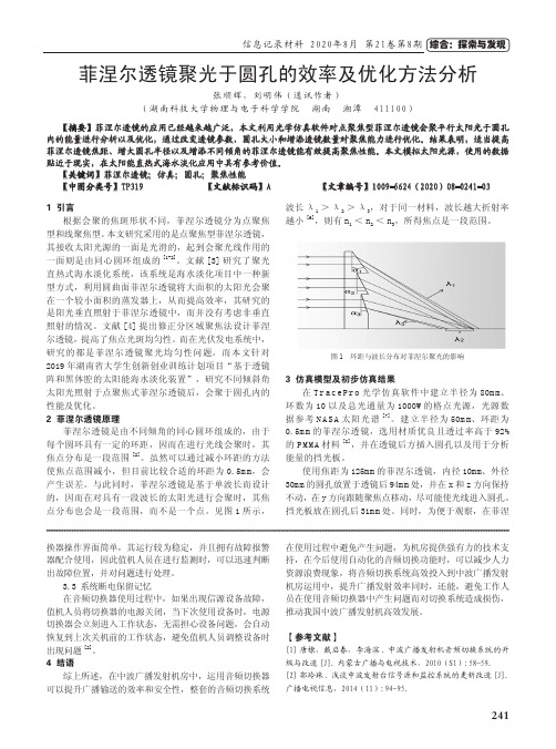
而本文针对2019年湖南省大学生创新创业训练计划项目“基于透镜阵和黑体腔的太阳能海水淡化装置”,研究不同倾斜角太阳光照射于点聚焦式菲涅尔透镜后,会聚于圆孔内的性能及优化。
LED菲涅尔透镜

光学元件是很精密的元件,制作成本较高,如果能减少元件的厚度,甚至做成片状透镜,则不但可以减少光学元件的尺寸,从而缩小灯具或其他设备的大小,还可以节省材料,降低成本。
由于厚度减少,光吸收也减少,灯具或仪器效率也会随之提高,因此做成高质量的薄片形的光学零件一直是光学设计追求的目标之一。
菲涅尔(Fresnel)透镜是一种片状的薄形透镜,它一直以其轻、薄、价格低廉优势而在一些方面得到应用。
但市场上的菲涅尔透镜多为等差半径的同心圆结构,其制作缺乏精确的光学设计过程,导致成像质量不是很高,有的甚至只是简单的波纹结构,其光学质量就更差了。
即使是较好的菲涅尔透镜,也是通常将普通透镜分为小段后,近似为折线,并经过不同距离的简单平移而形成,这些设计方法上的缺陷造成了菲涅尔透镜的低质量。
LED体积很小,但市场上销售的LED用杯状透镜大都厚度在10mm以上,这成为LED在某些场合应用的致命问题,虽然可以用菲涅尔透镜来减薄透镜的厚度和减少光吸收,但如何进行精确的光学设计却很少见到文献报道。
本文介绍的是能获得精确的超薄锯齿形透镜的设计方法,其光学质量好,光线利用率较高。
因为一般的菲涅尔透镜在理论上就存在浪费,即透过透镜的光线理论上就有一部分不能到达设计的目的地,本方法得到的透镜对点光源来说理论上不存在浪费。
此外,各个小锯齿之间的距离也可根据需要而不同,而且在同一透镜中不同位置的锯齿间距也可变化,从而使这种方法设计的锯齿形透镜有更广泛的适应性,即它可以适应不同的使用条件和不同的加工条件的需求。
这种锯齿形透镜适用LED为光源的二次光学透镜。
对于LED这种尺寸很小的光源,具有小而薄的光学透镜是非常有意义的。
一、设计原理单个透镜一般是一个表面形状为曲面的透明材料,其作用是改变光线的方向,形成所需的光强空间分布。
其缺点是往往比较厚,因此体积大成本高,而且吸收也就大,特别是曲率大的透镜更是如此。
为简单计,举一个平凸透镜的例子,原始的平凹透镜见图1(a),相应地传统的菲涅尔透镜见图1(b),为了说明原理,图中齿距画得比较大。
菲涅尔透镜 参数 计算

菲涅尔透镜参数计算【摘要】菲涅尔透镜是一种特殊的透镜结构,广泛应用于光学系统中。
本文从菲涅尔透镜的原理和应用出发,详细介绍了菲涅尔透镜的参数确定方法、计算公式、评估标准,以及效率和性能优化。
菲涅尔透镜参数计算的重要性在于能够准确地设计和优化光学系统,提高其性能和效率。
未来,随着光学技术的不断发展,菲涅尔透镜参数计算也将迎来更广阔的应用前景,为光学系统的设计和研发提供更加精准的技术支持。
在实际应用中,人们可以根据所需的光学系统设计要求和性能指标,进行菲涅尔透镜参数计算,以获得最佳的光学效果和性能表现。
【关键词】菲涅尔透镜、参数、计算、原理、应用、确定方法、计算公式、评估标准、效率、性能优化、重要性、发展前景、应用前景1. 引言1.1 菲涅尔透镜参数计算菲涅尔透镜参数计算是指在设计和制造菲涅尔透镜时,需要对其各项参数进行准确计算和评估的过程。
菲涅尔透镜是一种特殊的透镜,通过其特殊的表面结构可以实现对光线的聚焦和分散,广泛应用于太阳能光伏系统、车灯、舞台灯光等领域。
在进行菲涅尔透镜参数计算时,首先需要理解菲涅尔透镜的原理和应用。
菲涅尔透镜的工作原理是通过其表面的环形凸台结构,使得光线在经过透镜时可以通过反射和折射来实现聚焦或分散。
菲涅尔透镜的参数确定方法包括材料选择、几何结构设计、曲率半径等方面,需要综合考虑光学性能和制造成本等因素。
计算菲涅尔透镜的参数主要涉及到曲率半径、焦距、光学直径、透镜形状等方面。
通过适当的公式和模拟软件,可以准确地计算出菲涅尔透镜的各项参数。
评估标准则是根据设计要求和应用场景来确定透镜的性能是否符合要求。
菲涅尔透镜参数计算的重要性在于可以确保产品的光学性能和稳定性,提高生产效率和节约成本。
随着技术的不断进步和应用领域的拓展,菲涅尔透镜参数计算的发展前景和应用前景也将变得更加广阔和重要。
2. 正文2.1 菲涅尔透镜的原理和应用菲涅尔透镜是一种特殊的透镜,它是由法国物理学家菲涅尔发明的。
菲涅尔透镜的制造方法

菲涅尔透镜的制造方法
菲涅尔透镜是一种特殊的透镜,它的制造方法与普通透镜有所不同。
本文将介绍菲涅尔透镜的制造方法。
菲涅尔透镜是由法国物理学家奥古斯丁·菲涅尔于19世纪初发明的。
它的制造方法是通过将透镜表面分成一系列圆环状的凸面镜片,然后将这些凸面镜片组合在一起形成一个整体。
这些凸面镜片的曲率半径逐渐减小,使得透镜的厚度变得更薄,从而减少了透镜的重量和成本。
菲涅尔透镜的制造方法可以分为以下几个步骤:
1. 设计透镜的形状和尺寸。
根据透镜的用途和要求,设计透镜的形状和尺寸,确定透镜的直径、焦距和曲率半径等参数。
2. 制作模具。
根据透镜的设计图纸,制作透镜的模具。
模具通常是由金属或塑料制成的,用于制造透镜的凸面镜片。
3. 制造凸面镜片。
将透镜的模具放入注塑机中,注入透镜材料,制造出一系列圆环状的凸面镜片。
这些凸面镜片的曲率半径逐渐减小,使得透镜的厚度变得更薄。
4. 组装透镜。
将一系列凸面镜片组合在一起,形成一个整体。
这些凸面镜片之间的间隙可以用胶水或其他粘合剂填充。
5. 检验透镜。
对透镜进行检验,确保透镜的质量符合要求。
检验透
镜的方法包括测量透镜的焦距、曲率半径和表面质量等。
菲涅尔透镜的制造方法是通过将透镜表面分成一系列圆环状的凸面镜片,然后将这些凸面镜片组合在一起形成一个整体。
这种制造方法可以减少透镜的重量和成本,使得菲涅尔透镜在光学仪器、汽车灯具、太阳能电池等领域得到广泛应用。
菲涅尔透镜设计实例

菲涅尔透镜设计实例菲涅尔透镜是一种特殊的透镜设计,与传统的球面透镜相比,它具有更薄、更轻、更便于制造和使用的特点。
菲涅尔透镜的设计方案广泛应用于各种领域,如航海、照明、摄影等。
本文将以菲涅尔透镜在太阳能集热器中的设计实例为例,来说明菲涅尔透镜的应用和优势。
一、菲涅尔透镜在太阳能集热器中的设计实例太阳能集热器是利用太阳辐射热能进行能量转换的装置,其中菲涅尔透镜被广泛应用于集光器的设计中。
集光器的作用是将太阳的光线集中到一个小面积上,从而提高热能的集中度,增加太阳能的利用效率。
在太阳能集热器中,菲涅尔透镜被设计成具有特殊的形状,以实现光线的聚焦效果。
其设计原理是通过透镜表面特殊的微结构,将原本通过球面透镜折射的光线改为通过透镜表面的微槽,从而达到减小透镜厚度、减轻透镜重量的目的。
二、菲涅尔透镜设计的优势相比传统的球面透镜,菲涅尔透镜设计具有以下几个优势:1. 薄型设计:菲涅尔透镜的微槽结构使得透镜的厚度大大减小,从而减轻了透镜的重量,便于集光器的制造和使用。
2. 高效集光:菲涅尔透镜的特殊结构使得光线可以更好地聚焦,提高了集光器的光能利用效率。
透过菲涅尔透镜的光线能够更集中地投射到集热器的接收面上,从而实现更高的热能转换效率。
3. 宽视场角:菲涅尔透镜的设计可以实现宽视场角,即可以从更广的角度接收太阳光线。
这使得菲涅尔透镜适用于需要广视场角的应用场景,如太阳能光伏系统中的太阳能跟踪器。
4. 易于制造:菲涅尔透镜的制造相对简单,与传统的球面透镜相比,节省了制造成本和时间。
这使得菲涅尔透镜在大规模生产中具有较高的可行性。
三、菲涅尔透镜设计的应用领域除了太阳能集热器,菲涅尔透镜的设计还广泛应用于其他领域。
以下是一些常见的应用领域:1. 航海导航:菲涅尔透镜常被用于航海灯塔中,通过将灯光聚焦,增强灯塔的可见性和远距离导航的效果。
2. 摄影器材:菲涅尔透镜的薄型设计使其成为相机镜头的理想选择之一。
它能够提供清晰、锐利的图像,同时减轻了相机的重量,便于携带和使用。
大视场菲涅尔透镜的聚光效率模拟和分析

大视场菲涅尔透镜的聚光效率模拟和分析第32卷第1期2010年2月光学仪器OPTICALINSTRUMENTSV o1.32.No.1February,2010文章编号:1005—5630(2010)01—0044-05大视场菲涅尔透镜的聚光效率模拟和分析吴旭婷,李湘宁,蔡伟(上海理工大学光电信息与计算机工程学院,上海200093)*摘要:大视场菲涅尔聚焦透镜在180.的范围内各个视场下均能实现较理想的聚焦.根据现有的大视场菲涅尔聚焦透镜的设计结果,利用Zemax软件在非序列环境下自定义面型的功能对该设计进行模拟分析.模拟菲涅尔透镜在不同方向的平行光照射下的聚焦情况.通过对不同方向的光线照射下探测器接收到能量的情况进行分析,得到了相应的聚光效率,为设计的可行性提供了分析依据.关键词:菲涅尔透镜;Zemax软件;大视场;聚光效率中图分类号:TP319文献标识码:Adoi:10.3969/j.issn.1005—5630.2010.01.010 ThesimulationandanalysisofthelargefieldFresnellens opticalconcentratorefficiencyWUXuting,LJXiangning,CAIWei (SchoolofOptical—ElectricalandComputerEngineering,UniversityofShanghaiforScienceandTechnology,Shanghai200093,China)Abstract:LargefieldFresnellensconcentratorcangetabetteropticalconcentratorefficiency ineachfieldofviewwithintheangleof180..OnthebasisofthedesignofthelargefieldFresnel concentratorlens.simulatebyusinguserdefinedsurfacefeatureinthenon-sequence environmentofZemax.SimulatetheopticalconcentratorsituationoftheFresnellenswhich areirradiatedbytheparallel—rayindifferentdirections.Basedonthesimulationandanalysisof thelargefieldFresnel1ensopticalconcentratorefficiencyindifferentdirection.providean analysisofthefeasibilityforthedesign.Keywords:Fresnellens;Zemaxsoftware;largefield;opticalconcentratorefficiency引言大视场菲涅尔聚焦透镜是用于会聚太阳光的一种光学元件,它要求对各个方向的太阳光均能实现聚焦,并有较高的聚光效率.对于菲涅尔透镜表面的槽沟,许多学者的研究证实,当出射面压槽沟时透镜的光学效率最高LI].设计根据大视场菲涅尔透镜的特殊聚光要求,着重研究出射面有槽沟的平板菲涅尔透镜在Zemax软件中的建模及光路的追迹,利用该软件自定义面型的功能,分析在不同方向的平行光照射下大视场菲涅尔聚焦透镜的聚光情况.从而为设计提供一个客观的评价,为实际运用提供分析依据.在大视场菲涅尔聚焦透镜的设计中主要运用了几何光学的聚焦原理,为了使太阳光照射时每个时刻收稿日期:2009—07—29作者简介:吴旭婷(1984一),女,浙江湖州人,硕士研究生,主要从事应用光学方面的研究.第1期吴旭婷,等:大视场菲涅尔透镜的聚光效率模拟和分析?45?都有正入射的光线,将整个透镜设计成半圆柱状,从而使系统具有了较大的视场.为了分析太阳光在各个时间段照射菲涅尔透镜时探测器所接受到的能量的情况,现借助Zemax软件对设计进行建模及仿真分析.Zemax软件提供了大量可供光学系统选用的内置面型,如:球面,非球面,ABCD 矩阵面,衍射面,变折射面等,除此以外用户还可以定制特殊面型.l工作原理菲涅尔透镜是一种非球面透镜,是由一系列同心棱形槽构成的.每个环带都相当于一个独立的折射面,在平行光垂直入射情况下,在其焦面上能得到一个无像差的会聚点.设计中依靠三棱镜序列实现菲涅尔的聚焦.在设计中应遵守基本的光学原理,光线入射到棱镜发生一次折射,由棱镜另一面射出发生二次折射[4].棱镜的顶角为a,棱镜材料折射率为,如图l所示.总偏向角与折射率,工作侧面角a和入射角的一般函数关系式为:/3一1一口+arcsin{sinl口一arcsinfsin(J__~i1l}(1)IL\/.JJ大视场菲涅尔聚焦透镜有非球面透镜的作用(在平行光垂直入射情况下,在其焦面上能得到一个无像差的会聚点),如图2所示.其每个棱齿都相当于一个独立的折射面,这些棱齿能使入射光线会聚到一个共同的焦点.干扰侧面,图1菲涅尔透镜的折射光学Fig.1DioptricsofFresnellens一一,}d/2,,d/2I图2焦距与透镜总宽度的比例关系示意图Fig.2Therelationshipbetweenthef~_alandlenswidth设计中的大视场菲涅尔聚焦透镜用于太阳光能的聚焦.为了使菲涅尔聚焦透镜在每个时间段都能接收正向入射的光能,并满足大视场的要求,设计中需要将所有的面元旋转180.得到一个半圆柱状的入射面.2系统模拟2.1菲涅尔透镜的结构该设计以实例做参照,选取合适的焦距.在实例中采用焦距为250mm,受光面的宽度为300mm,一个棱齿的宽度a为0.5mm.总共具有600个齿,由于齿的左右两边是对称的,所以只要计算一边的齿.材料也是关键的因素,这里选用有优质透光率的聚碳酸酯(polycarbonate,PC),折射率,z一1.587,具有高透光率(透光率可达90).菲涅尔聚焦透镜的棱齿在光线正入射的情况下使光线偏折并向焦平面会聚,这时在中心距处入射光的偏向角应是:一arctan()(2),J,工作侧面角a的一般数学表达式为:口一—arctan[sin01--—sin(0,--f1)~(3)口一~O~/*,2--sin01--COS(1一46?光学仪器第32卷在Zemax建模时只考虑正向人射时的情况,即式(3)中01—0.,sin01—0的情况,再结合齿的宽度即可求得每个齿的高度h=a*Ot,理想的聚光情况如图3所示.根据设计要求需要将透镜面旋转180.,得到一个半圆柱的聚光表面,从而使之能接收到各个时间段正向入射的光线.在实际聚焦时,由于每个齿都有一定的宽度,在宽度范围内只有一条光线是满足严格的点聚焦,而并不是宽度范围内的所有光线都是严格的点聚焦过程,所以在焦点附近是一个有一定宽度的线聚焦.在设计中,探测器的宽度为5mm,长度为500mm,放置在菲涅尔聚焦透镜的焦平面上.2.2建模和光线模拟按上述要求及计算结果完成大视场菲涅尔聚焦透镜的结构尺寸的设定,可以在Zemax非序列模式下对整个系统建模进行光路模拟,从而观察其实际效果[5].建模方式:运用Zemax中的列表径向,面元阵列,并以TOB为副档名进行建模.根据上述程序运行所得的计算结果,得到构成透镜齿棱的每个点的位置(在Zemax中,,成右手坐标系),即每一个值对应一个值,这些Y,值可以组成一个TOB格式的数据文件.由于一个TOB文件的最大容纳的数据为246,在设计中需要有多个点构成整个聚光板,因此需要用多个TOB文件相拼接来完成整个系统的设计,从而在Y,平面上得到一个菲涅尔聚焦透镜的一个截面.由于根据数据所建的模型只是菲涅尔聚焦透镜的一个截面,为了得到一个立体的半圆柱状的聚光面,需要在此基础上再将其绕z轴旋转180.得到模型,如图3所示.在建模中为了能使光源,探测器以及菲涅尔聚焦透镜的受光照面在同一轴上,需要将整个菲涅尔聚焦透镜绕Y轴转--90..在设计的建模中,为了更好地使光线经过菲涅尔透镜后聚焦,在菲涅尔聚焦透镜的截面旋转180.时,尽可能地运用多次平滑,使得菲涅尔聚焦透镜趋近于半圆柱状,从而在模拟中得到更好的效果,如图4所示.在运行前,按工作要求设置好参数,将长500mm,宽5mm的探测器放置在焦平面位置上,即可进行光路模拟.图3各棱齿理想偏向角示意图Fig.3Theidealangulardeviation图4菲涅尔聚焦透镜模型图Fig.4ModelofFresnellens利用Zemax软件模拟不同视场的光照射菲涅尔聚焦透镜的情况,在模拟前设置好光源的各项参数,使光能以不同视场角度的平行光人射,即可模拟不同时刻下光照射时的情形,观察探测器上的能量情况.3分析与讨论设计以覆盖整个透镜齿棱的光能为单位,通过旋转光源的办法,得到以不同视场的平行光照射菲涅尔聚焦透镜的情形.根据在长250mm,宽5ram的探测器上接收到的能量分布情况进行分析,组图5(a),(b)为0.时探测器上接收到的能量,组图6(a),(b)为4O.时探测器上接收到的能量. 由图5,图6可以看出,大部分光能集中在探测器的5mm宽度内.按照前面的分析,同样的方法再取入射光束宽度为整个人射光能量的一半时(所取光束是正入射方向附近的光),两组光束都以每隔10.为测量对象取点,根据得到的有关数据得到如图7所示的分布曲线.第1期吴旭婷,等:大视场菲涅尔透镜的聚光效率模拟和分析?47?(a)0.角入射能量分布图(a)Energydistributionof0.incidentXcoordinatevalueInc0herentirradiance(b)0.角入射能量横向分布图(b)Transverseenergydislribufionof0.incident图5O.角入射时能量探测Fig.5EnergydetectorofO.incident(a)40.角入射能量分布图(a)Energydistributionof40.incidentXcoordinatevalueIncoherentirradianee(b)4O.角入射聚焦能量横向分布图(b)Transverseenergydistributionof40.incident图640.角入射时能量探测Fig.6Energydetectorof40.incident图7中z轴表示光源以不同角度的入射情况,Y轴表示长500mm宽5ram的探测器上所对应接收到的全部光能的百分比(即光能利用率).由图中所示的数据曲线显示,设计虽然在一定程度上实现了聚光板的聚光效果,但是聚光效率比较低,而且从图中可以看出光从正入射到以20.角人射的范围内探测器所接收的能量几乎是线性下降的.从模拟本身看,设计存在缺陷,光能的利用率比较低,不能得到理想的效果.经过图7中两组分布曲线的比较,发现在入射光束宽度缩减为原入射光能量的一半时(所取光线是正入射方向附近的光),由图得知探测器上所聚集到的能量几乎是原来能量的80左右.这就证明了,离正入射方向较远的光能对最终探测器接收到的能量是比较小的,光能的利用率较低,探测器上接收的主要光能大多来自于正入射附近的光能.Incidentangle/(.)图7光能利用率随入射光角度变化图Fig.7Condenserenergyratiowiththedifferentincidentangles通过运用Zemax软件的自定义功能进行建模,并模拟了各个不同方向平行光人射后的聚光情况,使设计者比较直观地看到设计的效果,大大提高了设计的效率,也使今后改进时有了更好的方向.4结束语在实际的建模模拟过程中,通过结合使用Zemax的TOB文件结构在非序列下的建模,较好地模拟了Q31宣量口苦—IouIITo0—rB_【口HJ【I10.IIIoII_|o/0/o焉矗.1u矗sllQpu0u48?光学仪器第32卷大视场菲涅尔聚焦透镜的实际聚焦情况,得到了一个比较客观的效果,对设计的可行性提供了分析依据.在对探测器所接收到的能量进行分析后,对整个设计的光学效率有了详实的了解,使整体设计效果在付诸于实践之前有了一个比较直观的判断,大大提高了设计的效率,有着充分的实际意义.也使类似的光学设计能依此相似的方法得到很好的建模分析,以求达到比较理想的效果.参考文献:[1]KRASINAEA,TVERIYAOVICHEV,RC)MANKEVICHA V.Opticalefficiencyofsol arengineeringFresnellensesEJ].AppliedSolarEnergy,1989,(6):6—1O.[2]张明,黄良甫,罗崇泰,等.空间用平板形菲涅尔透镜的设计和光学效率研究[J].光电工程,2001,28(5):l8—21.[3]王成良,李湘宁,贺莉清.应用Zemax软件构造特殊面型[J].光学仪器,2001,23(3):23—26.E4]郁道银,谈恒英.光学工程[M=].北京:机械工业出版社,2004.[5]徐欢,李湘宁,周果.基于Zemax软件的大齿距等厚菲涅尔透镜的设计_J].上海理工大,2007,29(1):99—1O2.量子级联激光器研究获重大突破新型中红外激光二极管转换效率超50%美国西北大学的研究人员研制出了一种小型中红外激光二极管,其转换效率超过5o.有关报道称这一成果是量子级联激光器(QCL)研究的重大突破,使量子级联激光器向多个领域的实际应用,包括对危险化学品的远程探测,迈出了重要一步.相关研究成果刊发在最近的《自然?光子学》杂志网络版上.量子级联激光器是一种发光机制异于传统半导体激光器的新型二极管激光器,根据量子力学原理设计,其发光波长可覆盖中红外区域.与传统的二极管激光器不同,量子级联激光器是单极器件,仅需电子即可运作,利用电子在一维量子化的导带问的跃迁来实现发光.经过多年的研究和工业化开发,现代近红外(波长在1m左右)激光二极管的转换效率已接近极值,而中红外(波长大于3ym)激光二极管却很难达到效率极值.先前的报道认为,即使冷却到低温状态,高效量子级联激光器的转换效率也不会高于40.美国西北大学量子器件研究中b(CQD)的研究人员通过优化激光器设备的材料质量,在量子级联激光器效率方面取得了突破性进展.他们剔除了在低温条件下激光器操作中非必要的设计元素,研制出的新型激光器在温度冷却到40K时,4.85ym波长光的转换效率达到了53%.该研究小组的领导者,美国西北大学麦考密克工程与应用科学学院电气工程和计算机科学教授玛尼杰?拉泽吉认为,这种高效激光器的问世是一个重大突破,这是科学家们首次使激光器发出的光能超过热能.她强调,激光器的转换效率突破5O这个门槛,是一个里程碑式的成就.报道称,提高转换效率依然是目前激光器研究的首要目标.而新型设备所展现的高效率,可大大扩展量子级联激光器的功率标定范围.最近的研究表明,伴随着量子级联激光器的广泛发展,单体脉冲激光器的输出功率已高达120W,而在一年前,只有34W.该研究得到了美国国防部高级研究计划局高效中红外激光器(EMIL)项目和美国海军研究所的共同资助.(摘自《科技日报》)。
柱面菲涅耳太阳聚光透镜的光学设计和光学效率

柱面菲涅耳太阳聚光透镜的光学设计和光学效率近年来,随着可再生能源的日益重要和普及,太阳能作为清洁能源的代表之一,受到了越来越多的关注。
而柱面菲涅耳太阳聚光透镜作为太阳能光伏发电的关键技术之一,其光学设计和光学效率更是备受关注。
柱面菲涅耳太阳聚光透镜是一种特殊的光学元件,能够将太阳光集中到光伏电池上,从而提高光伏电池的发电效率。
它通常由一系列的柱面透镜组成,每个透镜都具有柱面和菲涅耳镜面结构,能够使入射的太阳光线集中聚焦。
而光学设计和光学效率则是其关键要素,直接影响着整个发电系统的性能和效益。
在进行柱面菲涅耳太阳聚光透镜的光学设计时,需要考虑诸多因素。
首先是透镜的材料选择,需要具有良好的耐候性和光学性能,能够准确地折射和聚焦太阳光。
其次是透镜的结构设计,柱面和菲涅耳镜面的曲率和尺寸需精确计算,以确保太阳光线能够被高效地聚焦。
最后是透镜的安装和调整,需要考虑光照条件和光伏电池的位置,以实现最佳的光学效果。
光学效率则是衡量柱面菲涅耳太阳聚光透镜性能的重要指标之一。
它直接反映了透镜将太阳光聚焦到光伏电池上的效率,影响着整个光伏发电系统的发电量和经济效益。
提高光学效率需要从多个方面着手,包括透镜的光学设计、材料的选择和加工工艺等。
还需要考虑透镜在不同季节和天气条件下的性能表现,以确保其在各种环境下都能发挥最佳的光学效果。
在我看来,柱面菲涅耳太阳聚光透镜的光学设计和光学效率是一个充满挑战和机遇的领域。
通过不断的研究和创新,我们可以改进透镜的结构和材料,提高其光学性能和光学效率,从而更好地应用于太阳能光伏发电领域,推动可再生能源的发展和利用。
总结而言,柱面菲涅耳太阳聚光透镜的光学设计和光学效率是太阳能光伏发电技术中不可或缺的重要环节。
通过深入研究和全面评估,我们可以不断优化其性能,提高光伏发电系统的发电效率和经济收益,为清洁能源的可持续发展做出贡献。
希望未来能有更多的科学家和工程师投入到这一领域,共同推动太阳能技术的进步和发展。
菲涅耳透镜的通光分析及设计方法探讨
文章编号:100525630(2006)0120034205菲涅耳透镜的通光分析及设计方法探讨Ξ陈 杰,李湘宁,叶宏伟(上海理工大学光电学院,上海200093) 摘要:研究了菲涅耳透镜成像质量差的原因,提出一种改进的方法,即改善轴外点的成像质量以增大菲涅耳透镜的视场。
分析了三种常用的设计菲涅耳透镜的方法,用光学设计软件Zem ax 模拟设计结果,对三种设计方法进行比较。
得出结论:像面为曲面时可校正场曲;基面和底面为曲面的菲涅耳透镜与平面型菲涅尔透镜相比彗差较小。
关键词:菲涅耳透镜;像差;设计;曲面中图分类号:O 43 文献标识码:AAna lyo is of Fresnel len s tran s m issiv ity and research of designCH EN J ie ,L I X iang 2n ing ,Y E H ong 2w ei(Co llege of Op tics and E lectronics ,U niversity of Shanghai fo r Science and T echno logy ,Shanghai 200093,Ch ina ) Abstract :T he flaw of F resnel len s w as analyzed ,and a m ethod w as b rough t up to b roaden the angle of F resnel len s and to i m p rove i m aging quality .T h ree m ethods of F resnel len s design w ere listed ,and there typ e of len s w ere si m u lated ,and the resu lts of si m u lati on s w ere com pared ,and the conclu si on is :cu rve detecto r can ligh ten field cu rvatu re .T he i m aging quality of cu rve F resnel len s is better than p lane one ,becau se com a aberrati on w as co rrected .Key words :F resnel len s ;aberrati on ;design ;cu rve1 引 言当前广泛使用的菲涅耳透镜普遍使用轴上点消球差的方法设计[1]。
用于光伏系统新型菲涅耳线聚焦聚光透镜设计
光子学报第31卷第2期 V o l131N o12 2002年2月 A CTA PHO TON I CA S I N I CA Feb ruary2002 用于光伏系统新型菲涅耳线聚焦聚光透镜设计Ξ汪 韬 李 辉 李宝霞 赛小锋 高鸿楷(中国科学院西安光学精密机械研究所,光电子学室710068)摘 要 根据边缘光线原理,优化设计太阳电池及光伏系统的菲涅耳线聚焦聚光透镜1设计光学聚光率为18×,可用于空间、地面光伏系统的聚光系统1分析了其集光角特性,表明该菲涅耳线聚焦棱镜具有大的集光角(±7°)1关键词 太阳电池;菲涅耳透镜;集光角0 引言 近年来,基于太阳能、风能等可再生能源技术发展迅速1特别是基于太阳能光伏发电技术,为空间卫星供电的电源系统和地面光伏发电系统,为未来解决能源问题提供了新的广阔前景1但其面临发电价格高昂和太阳电池材料紧缺、昂贵的问题,需要进一步地降低成本和提高效率1为减少太阳电池片的实际用量,人们早已开始了太阳电池聚光器的研究1聚光系统主要为反射式1(如CPC、S M T S等)和透射式(F resnel,全息等)两种1特别是Ga InP2 GaA s Ge级联太阳电池的研制成功2,其较Si电池效率高、抗辐射、耐高温1非常适用于聚光型太阳电池1而且随光学树脂的应用发展,如聚碳酸酯、PMM A(聚甲基丙烯酸甲酯)和聚苯乙烯等,具有耐冲击强度高、相对密度小,透过率高,在太阳光谱的013~2Λm范围内透过率达92%以上,与光学玻璃相差无几1其光学性能优良,抗老化,成型工艺简单、产品成本低廉1利用光学树脂透镜和级联太阳电池合成的聚光型太阳电池极大地提高单位电池片产生的电量1大大降低了发电成本,提高了太阳能光伏发电的竞争力3,41早先点聚焦菲涅耳聚光透镜具有高的聚光率,但其必须对太阳进行二维跟踪1我们采用三维优化设计,考虑太阳能电池的热退化效应,设计具有较大集光角、只对太阳进行一维跟踪的线聚焦菲涅耳聚光透镜11 设计原理菲涅耳聚光透镜其根本目的为增加太阳电池上的太阳辐射功率的密度1由于菲涅耳非成象光学,无需考虑象的精度,在入射角范围内将能量聚焦于一定范围内,无需点聚焦51遵循折射原理(Snell定理)n1sin(i1)=n2sin(i2)当采用最小偏折角棱镜时,菲涅耳聚光透镜反射损失为最小,即为入射光线与顶面的法线的夹角等于出射光线与底面法线的夹角712 设计方法考虑因素:1)棱镜组对光的吸收随棱镜的厚度增加而变大,同时由于棱镜元的底边缘造成的通光量的损失也急剧变大,所以棱镜的厚度要尽可能的薄1单棱镜太薄将造成实际加工的困难,我们取其最大厚度为1mm12)菲涅耳聚光透镜的焦距直接影响电池组件集光角和光学聚光率的大小,同时影响电池组件的体积13)电池组件集光角的设计,集光角越大,电池组件对太阳的入射的方向不敏感,对系统瞄准太阳的能力要求低,同时它也直接影响光学聚光率的大小1对±Η截面内入射角,不同季节,每天太阳倾角的变化不同,正Ξ国家自然科学基金资助项目 收稿日期:2001206213午前后4小时夏天变化为±2°,冬天变化为±6°,太阳本身的有限长角为±015°,加上聚光器斜率误差,所以菲涅耳聚光棱镜的集光角设计值≥±615°14)折射率n 采用太阳电池吸收光谱的中心波长600nm 处折射率为114881先由0位置与接受面的相对位置设计第一棱镜元,确定其参量棱镜顶角角度Α1、棱镜倾角Β1、棱镜元宽度X 1,递进优化之1再在棱镜1基础上连接设计棱镜2,确定其参量Α2、Β2、X 2,递进优化1以此类推,得到第n 棱镜参量(Αn ,Βn ,X n )1由此得到棱镜组参量(Α1Α2…Αn ,Β1Β2…Βn ,X 1X 2…X n )1如图1,设计流程图见图21采用new ton 法逼近,至满足判据,结束该棱镜元参量的搜索1进行下一棱镜元参量的搜索1判据为 d x -d 0 <Ε,式中图1 光线在棱镜上的折射示意图F ig .1 Schem atic of rays refracti on on the F resnel lens 图2 菲涅耳线聚焦聚光棱镜的设计流程图 F ig .2 F low chart of the op ti m um line 2focu s F resnel len sd x 为入射角为Η时的光线的偏折角,d 0为光线投射到电池表面所需的偏折角,Ε为极小量1Η、Ω分别为入射角在棱镜端面和垂直端面内的投影1光学聚光率定义为E l E o ,E l 为有棱镜情况下光辐射密度,E o 为无棱镜情况下光辐射密度11光学聚光率为会聚比与光效率的积1总的光学聚光率为各棱镜元的光学聚光率的和1计算公式为c (Η,7)=6nT (Η,7,n )(A l (n ) A o (n ))T (Η,7,n )为第n 棱镜的透过率,A l (n )为第n 棱镜的出射孔径,A o (n )为第n 棱镜的入射孔径1其设计外形如图3,其光学聚光率见图41 图3 菲涅耳线聚焦聚光棱镜外形截面图 F ig .3 Schem atic of truncated the op ti m umline 2focu s F resnel lens 图4 不同Η、7菲涅耳线聚焦聚光棱镜的聚光率 F ig .4 Op tical concen trati on rati o of the op ti m umline 2focu s F resnel len s in differen t Η,73 损失分析太阳光穿过菲涅耳棱镜,在棱镜上表面和下表面分别发生反射1棱镜倾角变大时,入射角变大,反射损失变大,透射光通量与入射角和棱镜顶角有关,当入射角与出射角相等时,透射光通量为最大1另外棱镜元的边缘也造成通光量的损失1当入射角Η太大时,一部分光线将投射到棱7912期 江韬等1用于光伏系统新型菲涅耳线聚焦聚光透镜设计镜的底边,只是这部分光线偏离预定方向,无法投射到太阳电池表面1所以应尽量减小棱镜元的底边宽度1即减少棱镜的厚度14 集光角特性分析如图4,在±7角平面内,其集光角达到±60°,光学聚光率对入射角的变化不敏感1在±60°之间都有较高的光学聚光率1这样在一天内不动电池组件从上午8时至下午4时都能充分利用太阳光1在±Η角平面内,其集光角达到±7°,具有较宽的集光角,大于太阳一天内南北方向的仰角变化15 焦距的影响如图5,相同的入射孔径,不同的焦距情况下的光学聚光率(7=0),大的焦距(f =360mm )有相对高的光学聚光率达21,但其集光角为±4°1当焦距变小(f =200mm )其集光角达到±8°,但其 图5 不同焦距下的光学聚光率和集光角特性 F ig .5 Effect on the op tical concen trato r rati oof Ηand erro r to lerance (7=Η)光学聚光率降低为161原因是焦距变小相应其f ×Η值减小,其集光角变大1焦距变小时菲涅耳聚光棱镜边缘部分偏折角变大,其反射损失加重,光效率降低,导致整个菲涅耳聚光棱镜的光学聚光率下降1在实际应用中,菲涅耳聚光棱镜应有尽量大的集光角,但是集光角设计的变大则造成光效率的相应减小,应考虑实际应用情况作相应的调整1理论上随电池表面光通量增加短路电流呈线性增加,开路电压呈指数增长1而电池的漏电电流不变化1这样V 增加,(c ×I -I l ) (I -I l )>c ,即电流增幅大于c 倍1这样电池输出功率为原先的c 倍以上,电池效率也有所升高1光学聚光率c 不能太高,否则电池表面温度太高导致电池系列电阻变大,电池效率将有所下降1以AM 115条件下1m 2太阳电池效率19%记,输出功率P 为190W ,配备18倍菲涅耳线聚焦聚光透镜后,由于电池表面温度升高不多,电池效率损失微小6,电池输出功率可达3400W 左右1大大提高了单位电池面积的发电量,降低了太阳电池组件的成本,提高了光伏发电的竞争力16 结论设计一种用于太阳电池的菲涅耳线聚焦聚光透镜,考察了焦距对其光学聚光率的影响1理论上棱镜越细密越好,但由于实际加工有一定的精度限制,所以应根据情况取舍1据此设计透射式的菲涅耳线聚焦聚光透镜,聚光量适中C =18,太阳电池的温度不高,减缓太阳电池的热退化效应,有利于延长其使用寿命1并且其较以往(±215.)具有较大的集光角±7.,便于实际应用1无须太阳跟踪系统,只需随着不同季节太阳纬度的变化,调整太阳电池组件南北方向的倾角1参考文献1 W elfo rd W T ,W in ston R .T he op tics of non i m aging concen trato rs .N er Yo rk :A cadem ic P ress ,1978,132~1382 Yeh Y C M ,et al .A dvances in p roducti on of cascade so lar cells fo r space .26th IEEE Pho tovo ltaic SpecialistsConference ,1997:827~8303 O ′N eillM J ,et al.Inflatab le len ses fo r space pho tovo ltaic concen trato r arrays .26th IEEE Pho tovo ltaic Specialists Conference ,1997:853~8564 Spence B R ,et al .T he scarlet array fo r h igh pow er GEO satellites .26th IEEE Pho tovo ltaic Specialists Conference ,1997:1027~10305 L o renzo E ,L uque A .F resnel len s analysis fo r so lar energy app licati on s .A pp l Op t ,1982,20(17):2941~29456 Ku rtz S R ,O ′N eillM J .E sti m ating and con tro lling ch rom atic aberrati on lo sses fo r tw o 2juncti on ,tw o 2term inal devicesin refractive concen trato r system s.25th IEEE Pho tovo ltaic Specialists Conference ,1996:361~3647 K ritchm an E M ,et al .(1979b )H igh ly concen trating F resnel L en ses .A pp l Op t ,1980,18(15):2688~2695891 光子学报 30卷A NE W D ESIGN OF L INE -FOCUS FRESNEL L ENSFOR PHOT OVOL TA I C POW ER S Y STE MW ang T ao ,L i H u i ,L i B aox ia ,Sai X iaofeng ,Gao HongkaiX i′an Institu te of Op tics and P recision M echan ics ,Ch inese A cad e m y of S ciences 710068R eceived date :2001206213Abstract A n arched line 2focu s F resnel len s is designed fo llow ing the edge ray p rinci p le by op ti m um m ethod .T h is k ind of F resnel len s cou ld be u sed in so lar concen trato r of sp ace and terrestrial p ho tovo ltaic pow er system .It ′s easier to track the sun in on ly one single ax is .It has op tic concen trato r rati o as 18.It also has better accep tance angle and low co st .Keywords F resnes len s ;So lar concen trato r ;A ccep tance angleW ang Tao w as bo rn in Shaanx i ,Ch ina ,in 1974.H e received the B .S degree and M .S degree from the N o rthw est U n iversity in 1996and 1999resp ectively .A t p resen t ,he is a Ph .D degree candidate in X i ′an In stitu te of O p tics and P recisi on M echan ics ,Ch inese A cadem y of Sciences .H is p resen t in terest is p ho tron ic m aterials and devices 19912期 江韬等1用于光伏系统新型菲涅耳线聚焦聚光透镜设计。
(完整版)基于菲涅尔透镜的配光设计

基于菲涅尔透镜的配光设计内容:一、概述二、设计方法三、设计步骤报告人:陈志强学号:************专业:光信15011、菲涅尔透镜概述菲涅尔透镜(Fresnel lens)又称螺纹透镜,是由法国物理学家奥古斯汀·菲涅尔(Augustin·Fresnel)发明的,他在1822年最初使用这种透镜设计用于建立一个玻璃菲涅尔透镜系统--灯塔透镜。
菲涅尔透镜多是由聚烯烃材料注压而成的薄片,也有玻璃制作的,镜片表面一面为光面,另一面刻录了由小到大的同心圆,它的纹理是利用光的干涉及扰射和根据相对灵敏度和接收角度要求来设计的,透镜的要求很高,一片优质的透镜必须是表面光洁,纹理清晰,其厚度随用途而变,多在1mm左右,特性为面积较大,厚度薄及侦测距离远。
2、基本原理假设一个透镜的折射能量仅仅发生在光学表面(如:透镜表面),拿掉尽可能多的光学材料,而保留表面的弯曲度。
(如图1-1)另外一种理解就是,透镜连续表面部分“坍陷”到一个平面上。
从剖面看,其表面由一系列锯齿型凹槽组成,中心部分是椭圆型弧线。
每个凹槽都与相邻凹槽之间角度不同,但都将光线集中一处,形成中心焦点,也就是透镜的焦点。
每个凹槽都可以看做一个独立的小透镜,把光线调整成平行光或聚光。
这种透镜还能够消除部分球差。
图1-13、光学特性使用普通的凸透镜,会出现边角变暗、模糊的现象,这是因为光的折射只发生在介质的交界面,凸透镜片较厚,光在玻璃中直线传播的部分会使得光线衰减。
如果可以去掉直线传播的部分,只保留发生折射的曲面,便能省下大量材料同时达到相同的聚光效果。
菲涅耳透镜就是采用这种原理的。
菲涅尔透镜看上去像一片有无数多个同心圆纹路(即菲涅耳带)的玻璃,却能达到凸透镜的效果,如果投射光源是平行光,汇聚投射后能够保持图像各处亮度的一致。
二、设计方法1、光源本设计光源采用给定的点源,在TP软件中可以找到格点光源来仿真。
2、目标光斑不同接收面的目标光斑有很大差异,具体如图3-9——图3-12。
光学现象中的菲涅尔衍射与菲涅尔透镜分析

光学现象中的菲涅尔衍射与菲涅尔透镜分析光学是一门研究光的传播和相互作用的学科,而光学现象中的菲涅尔衍射与菲涅尔透镜则是光学中的两个重要概念。
本文将对菲涅尔衍射与菲涅尔透镜进行分析,探讨其原理和应用。
一、菲涅尔衍射菲涅尔衍射是一种光波在绕过障碍物或通过缝隙后发生的衍射现象。
它是由法国物理学家菲涅尔在19世纪初提出的。
在菲涅尔衍射中,光波通过一个有限大小的孔或缝隙时,会发生衍射现象,形成一系列明暗相间的衍射环或条纹。
菲涅尔衍射的原理可以通过菲涅尔衍射公式来描述。
该公式是由菲涅尔根据赫姆霍兹衍射积分公式推导而得。
菲涅尔衍射公式表达了衍射波的振幅与入射波的振幅之间的关系。
通过菲涅尔衍射公式,我们可以计算出衍射波的幅度和相位分布。
菲涅尔衍射在实际应用中有着广泛的应用。
例如,它可以用于显微镜中的分辨率提高,通过控制光的衍射现象可以增强显微镜的分辨能力。
此外,菲涅尔衍射还可以用于光学数据存储、光学通信等领域。
二、菲涅尔透镜菲涅尔透镜是一种特殊的光学透镜,它是由一系列环形透镜片组成的。
菲涅尔透镜的设计原理是通过将传统的连续曲面透镜分解成一系列薄透镜片,从而减小透镜的厚度和重量。
菲涅尔透镜的优点在于它可以提供与传统透镜相当的成像质量,同时又具有更轻、更薄的特点。
这使得菲涅尔透镜在光学系统中得到广泛应用。
例如,在摄影镜头中,菲涅尔透镜可以用于减小镜头尺寸和重量,提高成像质量。
在激光器中,菲涅尔透镜可以用于聚焦激光束,实现高能量密度的光束。
菲涅尔透镜的工作原理是通过透镜片的形状和相位差来实现光的聚焦。
每个透镜片的形状和相位差都被精确设计,以使得光线在经过透镜片时能够被正确聚焦。
通过合理的设计和组合,菲涅尔透镜可以实现高质量的成像效果。
总结菲涅尔衍射与菲涅尔透镜是光学中的两个重要概念。
菲涅尔衍射描述了光波在通过孔隙或缝隙时发生的衍射现象,而菲涅尔透镜则是一种特殊的透镜,通过分解连续曲面透镜成一系列薄透镜片来减小透镜的厚度和重量。
菲涅尔透镜设计方法介绍

The Fresnel LensCenturies ago, it was recognized that the contour of the refracting surface of a conventional lens defines its focusing properties. The bulk of material between the refracting sur-faces has no effect (other than increasing absorption losses) on the optical properties of the lens. In a F resnel (point focus) lens the bulk of material has been reduced by the extraction of a set of coaxial annular cylinders of material, as shown in Figure 1. (Positive focal length Fresnel lenses are almost universally plano-convex.) The contour of the curved surface is thus approximated by right circular cylindrical portions, which do not contribute to the lens’ optical proper-ties, intersected by conical portions called “grooves.” Near the center of the lens, these inclined surfaces or “grooves”are nearly parallel to the plane face; toward the outer edge, the inclined surfaces become extremely steep, especially for lenses of low f–number. The inclined surface of each groove is the corresponding portion of the original aspheric surface, translated toward the plano surface of the lens; the angle of each groove is modified slightly from that of the original aspheric profile to compensate for this translation.The earliest stepped-surface lens was suggested in 1748by Count Buffon, who proposed to grind out material from the plano side of the lens until he was left with thin sections of material following the original spherical surface of the lens, as shown schematically in F igure 2a). Buffon’s work was followed by that of Condorcet and Sir D. Brewster, both of whom designed built-up lenses made of stepped annuli. The aspheric Fresnel lens was invented in 1822 by Augustin Jean F resnel (1788–1827), a F rench mathematician and physicist also credited with resolving the dispute between the classical corpuscular and wave theories of light through his careful experiments on diffraction. Fresnel’s original lens was used in a lighthouse on the river Gironde; the main innovation embodied in Fresnel’s design was that the center of curvature of each ring receded along the axis according to its distance from the center, so as practically to eliminate spherical aberration. Fresnel’s original design, including the spherical-surfaced central section, is shown schematically in Figure 2b). The early Fresnel lenses were cut and polished in glass – an expensive process, and one limited to a few large grooves. Figure 3 shows a Fresnel lens, constructed in this way, which is used in the lighthouse at St Augustine, Florida, USA. The large aperture and low absorption of F resnel lenses were especially important for use with the weak lamps found in lighthouses before the invention of high-brightness light sources in the 1900s. The illustrated system is catadioptric: the glass rings above and below the Fresnel lens band in the center of the light are totally-internally-reflecting prisms, which serve to collect an additional frac-tion of the light from the source. The use of catadioptric sys-tems in lighthouses was also due to Fresnel.Until the 1950’s, quality Fresnel lenses were made from glass by the same grinding and polishing techniques used in 1822. Cheap Fresnel lenses were made by pressing hot glass into metal molds; because of the high surface tension of glass, Fresnel lenses made in this way lacked the necessary detail, and were poor indeed.In the last forty years or so, the advent of optical-quality plastics, compression and injection molding techniques,Figure 1 Construction of a Fresnel lens from its correspond-ing asphere. Each groove of the Fresnel lens is asmall piece of the aspheric surface, translated to-ward the plano side of the lens. The tilt of each sur-face must be modified slightly from that of theoriginal portion of aspheric surface, in order tocompensate for the translation.Figure 2 Early stepped–surface lenses. In both illustrations the black area is material, and the dashed curvesrepresent the original contours of the lenses. a)shows the lens suggested by Count Buffon (1748),where material was removed from the plano sideof the lens in order to reduce the thickness. b)shows the original lens of Fresnel (1822), the cen-tral ring of which had a spherical surface. InFresnel’s lens, the center of curvature of each ringwas displaced according to the distance of thatring from the center, so as to eliminate sphericalaberration.a)b)© Copyright Fresnel Technologies, Inc. 20032© Copyright Fresnel Technologies, Inc. 20033and computer-controlled machining have made possible the manufacture and wide application of F resnel lenses of higher optical quality than the finest glass F resnel lenses.Modern computer-controlled machining methods can be used to cut the surface of each cone precisely so as to bring all paraxial rays into focus at exactly the same point, avoid-ing spherical aberration. Better still, newer methods can be used to cut each refracting surface in the correct aspheric contour (rather than as a conical approximation to this con-tour), thus avoiding even the width of the groove (typically 0.1 to 1 mm) as a limit to the sharpness of the focus. Even though each groove or facet brings light precisely to a focus,the breaking up of the wavefront by the discontinuous sur-face of a F resnel lens degrades the visible image quality.Except in certain situations discussed later, Fresnel lenses are usually not recommended for imaging applications in the visible light region of the spectrum.The characteristics of the aspheric “correction”The grinding and polishing techniques used in the manufac-ture of conventional optics lead to spherical surfaces. Spher-ical surfaces produce optics with longitudinal spherical aberration, which occurs when different annular sections of the optic bring light rays to a focus at different points along the optical axis. This phenomenon is illustrated for a positive focal length, plano-convex conventional lens in Figure 4 (in all optical illustrations in this brochure, light is taken to propagate from left to right). The lens illustrated is a section of a sphere with 1" (25 mm) radius of curvature, 1.6"(36 mm) in diameter; the index of refraction of the material is 1.5, typical both for optical glasses and for our plastics materials. The focal length of the illustrated lens is thus 2"(50 mm), and the aperture is /1.3. As is evident from the figure, the longitudinal spherical aberration is very strong.Single-element spherical lenses are typically restricted to much smaller apertures (higher –numbers) than this,because longitudinal spherical aberration of the magnitude shown in Figure 4 is generally unacceptable. Figure 5 shows an aspheric lens of the same focal length and –number;note that the surface contour is modified from the spherical profile in such a way as to bring rays passing through all points on the lens to a focus at the same position on the opti-cal axis. A lens made with the aspheric profile illustrated in Figure 5, therefore, exhibits no longitudinal spherical aber-ration for rays parallel to the optical axis.Since Fresnel lenses are made from the beginning to the correct aspheric profile, the notion of “correcting for spheri-cal aberration” is not meaningful for F resnel lenses. The lenses are more accurately characterized as “free from spherical aberration.” The combination of the aspheric sur-face (which eliminates longitudinal spherical aberration)and the thinness of the lens (which substantially reduces both absorption losses in the material and the change of those losses across the lens profile) allows F resnel lenses with acceptable performance to be made with very large apertures. In fact, F resnel lenses typically have far larger apertures (smaller –numbers) than the /1.3 illustrated in Figure 4.Figure 6 compares an aspheric plano-convex lens with an aspheric F resnel lens (the F resnel lens’ groove structure isf f f f f Figure 3 The light from the St Augustine, Florida (USA) light-house, showing the glass Fresnel optical system used in the lighthouse. The optical system is about 12 feet (3.5 m) tall and 7 feet (2 m) in diameter.Figure 4Illustration of longitudinal spherical aberration.The rays shown were traced through an /1.3 spherical-surface lens; the focus is evidentlyspread out over a considerable distance along theoptical axis.f© Copyright Fresnel Technologies, Inc. 20034tive focal length (EFL), quential, so that the Fresnel lens.focus. (This type of F application and reversed.for a given focal length tion (where object distances, i.e. the conjugates), and are found to be and for the conjugate ratio 3:1. Even though a lens may be designed for conjugates in some particular ratio, it can be used at other finite conjugate ratios as well. The error introduced is usually reasonably small.Fresnel lenses are normally fabricated so that they are correct for the case of grooves toward the collimated beam,plano side toward the focus (grooves “out”). They can, how-ever, be fabricated so that they are correct for the case of grooves toward the focus, plano side toward the collimated beam (grooves “in”). In this case, there is no refraction at all on the plano side for a collimated beam traveling parallel to the optical axis. In the grooves “out” case, both surfaces refract the light more or less equally. The case of grooves toward the collimated beam (“out”) is the optically preferred case. The main difference is that in the grooves “in” case, the grooves at the outer periphery of the lens are canted at muchf f f 1f ⁄1i ⁄1o ⁄+=i 4f 4f 3⁄ Figure 6 Comparison between an aspheric conventionallens and an aspheric Fresnel lens, illustrating the optical quantities discussed in the text.smaller angles to the plano surface than they would be in spherical or grooves “out” lenses. Because the angles made with the plano surface are relatively small toward the periphery of the lens, any small warpage or tilt of the lens surface, or any small deviation of a light ray from parallelism with the optical axis, leads to a very large deviation from the ideal in the angle between the light ray and the lens surface.These errors lead directly to a decrease in the collection effi-ciency of a grooves “in” lens relative to a grooves “out” lens of the same focal length and –number.A third case which is sometimes encountered is that of a Fresnel lens which is correct for grooves “out,” used with its grooves toward the focus (grooves “out” turned groovesf© Copyright Fresnel Technologies, Inc. 20035for angles of intersection between a light ray and the normalto a surface larger than the critical angle = ,where the ray is traveling from a medium of index of refrac-tion into a medium of index of refraction . It is evident that total internal reflection only occurs for , since in the case is greater than π /2 and therefore not physically meaningful.) This phenomenon makes the portion of a grooves “out” lens turned grooves “in” lens past about /1 useless. The phenomenon is easily observed as an appar-ent “silvering” of the outer portion of a grooves “out” lens when its grooves are turned to face the shorter conjugate.Total internal reflection does not occur for grooves “out”lenses used in their correct orientation because the only large-angle intersection between the light and the lens sur-face occurs at a transition from low to high refractive index.MaterialsOur standard materials for visible light applications are acrylic, polycarbonate and rigid vinyl. These materials are suitable for some near infrared applications as well, as dis-cussed later in this brochure. Figure 9 shows useful transmis-sion ranges for a variety of plastics materials. Materials suitable for infrared applications are described in detail in our POLY IR® brochure.The first step in choosing a material is to match the mate-rial to the spectral domain of the application. Other consid-erations include thickness, rigidity, service temperature,weatherability, and other physical properties listed in the table of properties on the next page.AcrylicOptical quality acrylic is the most widely applicable mate-rial, and is a good general-purpose material in the visible. Its transmittance is nearly flat and almost 92% from the ultravi-olet to the near infrared; acrylic may additionally be speci-fied to be UV transmitting (UVT acrylic) or UV filtering (UVF acrylic). The transmittance of our standard acrylic materials between 0.2 µm and 2.2 µm is shown in F igure 10 for a thickness of 1/8" (3.2 mm). Standard acrylic thicknesses are 0.060" (1.5 mm), 0.090" (2.3 mm), and 0.125" (3.2 mm). Rigid vinylRigid vinyl has a number of characteristics which make it both affordable and very suitable for certain applications. It has a high index of refraction; it is reasonably inexpensive;and it can be die-cut. However, polycarbonate has very sim-ilar properties, without the problems associated with rigid vinyl, and its use is encouraged over that of rigid vinyl in new applications. Rigid vinyl has about the same tempera-ture range as acrylic and is naturally fire-retardant. The trans-mittance of rigid vinyl between 0.2 µm and 2.5 µm is shown in F igure 11 for a nominal thickness of 0.030" (0.76 mm).Standard thicknesses for rigid vinyl are 0.010" (0.25 mm),0.015" (0.38 mm), 0.020" (0.51 mm), and 0.030" (0.76 mm). PolycarbonatePolycarbonate is spectrally similar to acrylic, but is useful at higher temperatures and has a very high impact resistance.The transmittance of polycarbonate between 0.2 µm and 2.2 µm is shown in Figure 12 for a nominal thickness of 1/8"θc sin –1n n '⁄()n n 'n 'n >n 'n <θc f Figure 7 Illustration of the strong asymmetry of the asphericFresnel lens. The illustrated lens is correct for the grooves facing the longer conjugate (grooves “out”). When it is turned around so that thegrooves face the shorter conjugate (grooves “out” turned grooves “in”), on-axis performance suffers. As discussed in the text, however, in the case where the grooves must face the shorter conjugate, a grooves “out” lens turned grooves “in” has some advantages over a lens correct for grooves “in.”Figure 8 Aspheric Fresnel lens correct for the grooves facingthe shorter conjugate (grooves “in”).© Copyright Fresnel Technologies, Inc. 20037Figure 12 Transmittance of polycarbonate as a function ofwavelength. Sample thickness = 1/8" (3.2 mm) nominal.Figure 13 The three typical configurations for producing acollimated beam of light: lens only, mirror only, and a combination of lens and mirror.(3.2 mm). Standard thicknesses available in polycarbonate are 0.010” (0.25 mm), 0.015” (0.38 mm), 0.020” (0.5 mm),0.030" (0.76 mm), 0.040” (1 mm), 0.050" (1.3 mm), 0.060"(1.5 mm), and 0.125" (3.2 mm).Focal length in a given materialThe focal lengths listed in the table at the end of this bro-chure are the effective focal lengths in optical grade acrylic.The effective focal length is different when a lens is manu-factured from a different material, but is easily calculated.The effective focal length in any other material iswhere is the refractive index of the material in question.T ypical Fresnel Lens ApplicationsCollimatorProducing a collimated beam from a point source could be said to be a perfect application for F resnel lenses. In this case the spatial distribution of light from the point source tends to favor the central portion of the lens, so that the total lens transmittance can be as much as 90%. The best optical results are obtained when the grooved side faces the longer conjugate.In practice, the point source is never actually a point source, but is extended, so that the imperfection of the coni-cal approximation to the aspheric groove shapes is never noticed.Figure 13 shows the three cases usually encountered in collimation: lens only, mirror only, and lens/mirror combina-tion. Note that adding a lens to the mirror-only case would produce extremely poor results. The mirror must be specially designed to image the light source very near itself.CollectorFocusing a collimated beam of light at a point is another popular use of F resnel lenses, and one for which F resnel lenses are at least adequate. Again, the grooved side toward the infinite conjugate is the optically preferred configura-tion. Because the collimated beam is assumed to be uni-form, there is a substantial loss through the lens in this case for marginal rays. The loss is caused by the increasing angles of incidence and emergence as the margin of the lens is approached. It can be predicted using Fresnel’s equations,which describe the reflection and transmission of light at an interface between media of differing refractive index. The loss due to reflection is graphed as a function of the angle between the incident ray and the (plane) interface in Figure 14.There are two additional losses which must be considered in demanding applications. One is due to the unavoidable width of the vertical step between grooves. This loss is gen-erally reasonably small in well-made F resnel lenses, but light scattered from the step brightens the focal plane and thereby reduces the contrast of an image.The other loss is due to shadowing and blocking effects caused by the vertical step. This loss does not exist for rays parallel to the optical axis striking grooves “in” lenses, but is present in all other cases. For rays making a large angle (20°EFL 1.491–n 1–--------------------EFL acrylic ,=n© Copyright Fresnel Technologies, Inc. 20038cant loss. F and invites your inquiries.Condenserdenser lens will even be frosted.plano–plano sheet.Field lenses (Fresnel screen “brighteners”)A Fresnel lens can be used to redirect the light at the edges of a frosted rear-projection display screen toward the viewer’s eyes, thus eliminating the “hot spot” often observed in such screens by brightening the edges of the display.Screens of this type include camera focusing screens. The grooves must face the light source in this application; the grooves often must therefore face the shorter conjugate, an exception to the usual rule.Conjugates for the field lens should be the distance from the projector lens on the grooved side, and the distance to the viewer on the frosted side. Fresnel Technologies, Inc. can supply suitable lenses with the plano side either optically polished or frosted.MagnifiersAn aspheric lens is an ideal magnifier from several points of view. When used at its conjugates, there is no distortion of the image (a rectangular grid remains a rectangular grid afterwhere is the lens’ focal length. This is usually taken astrue for a virtual image at infinity. A magnifier with a focallength of 50 mm will then have a power of 5X.Because they can be made large, Fresnel lenses are gen-erally used to magnify objects slightly, perhaps as little as 1.2 or 1.5X. One usually expects to see the entire object at once within the Fresnel lens, so that the lens must then be 1.2 or 1.5 times the size of the object in both length and width.Please observe caution when using a F resnel lens as a magnifier around strong light sources, lasers, and in sun-light.ImagingFresnel Technologies, Inc. does not generally recommend its Fresnel lenses for image formation in the visible region of the spectrum, but there are some important exceptions.θff M θ'θ---250mm f-------------------== ,Imaging generally demands some substantial field of view, or the image is uninteresting. With simple plano-convex lenses, coma degrades the image only a degree or so off axis. Chromatic aberration blurs the image as well. As in camera or copy lenses, the faster the lens (the smaller the f–number), the worse the problem becomes – and the small f–numbers of Fresnel lenses are very tempting.The important exceptions include two cases: rays pre-cisely parallel to the axis of the lens (laser rangefinder, for example) and imaging onto a large detector (for instance, a pyroelectric detector or a thermopile).Imaging can be treated as a generalization of collection. Near-infrared applicationsAll of the above applications remain relevant into the near infrared, and the preferred materials (acrylic, polycarbonate, and rigid vinyl) from the visible region can be used to about 1.3 µm without difficulty. The refractive index of each of these materials is slightly lower there, but our plastics are not strongly dispersive.Process monitoring at 3.4 µmAll hydrocarbons – solids, liquids, and gases – exhibit a strong absorption of 3.4 µm radiation. (3.4 µm is the wave-length of the C–H stretch.) POLY IR® 5 is specially formu-lated to contain no hydrogen, and is thus free of the C–H stretch absorption. It can be used to monitor hydrocarbons in a wide variety of applications: uses have ranged from methane monitoring above landfills to process control on production lines.Passive infrared applicationsThe collection of infrared radiation emitted by humans and other warm-blooded animals has become a major applica-tion area for Fresnel lenses. This application requires that the lenses be transparent between approximately the wave-lengths of 8 µm and 14 µm, the region of maximum contrast betwen warm bodies and typical backgrounds.Passive infrared applications are discussed in our bro-chure on POLY IR® infrared-transmitting materials, and in the notes accompanying our passive infrared lens array data sheets.ThermometryOptical pyrometry can be extended toward infrared wave-lengths (and therefore lower temperatures) with appropriate sensors and optics. Fresnel lenses made from our POLY IR®infrared-transmitting materials are used with a variety of bolometers and thermopiles. Our POLY IR® 1 and 2 materi-als are most appropriate for higher temperatures (shorter wavelengths); they can be used for lower-temperature appli-cations as well. Our POLY IR® 4 material is also useful there, particularly in white. Please refer to our POLY IR®infrared-transmitting materials brochure for more informa-tion.Solar Energy CollectionFresnel lenses have often been used as concentrators for photovoltaic cells or arrays of cells in solar energy devices. We can certainly recommend them for this application,though reflectors and nonimaging concentrators are often superior. However, Fresnel Technologies, Inc. does not man-ufacture any Fresnel lenses with uniform energy distribution over typical photovoltaic cell areas; our products all have a damaging “hot spot” in the focal plane. We therefore do not recommend our own products for this application; neither do we manufacture mirrors or nonimaging collectors useful for solar devices.Please use caution with our Fresnel lenses in sunlight. The sun's image can easily ignite flammable materials quickly, and can damage materials which are not flammable. These cautions particularly apply to clothing, skin, and eyes, in both sunlight and laser light.Special OpticsFresnel Technologies, Inc. offers several types of optical ele-ments related to Fresnel lenses. These include:Cylindrical Fresnel lensesA cylindrical Fresnel lens is a collapsed version of a conven-tional cylindrical lens. These lenses can be used in any application which requires focusing in only one dimension of the focal plane. In some cases, two separate cylindrical lenses may be combined to obtain different focal properties in the x and y dimensions of the focal plane; these configu-rations are representative of one type of anamorphic optic. A variety of cylindrical Fresnel lenses is available, with typical –numbers between /1 and /2. Both positive and negative focal lengths are available.Fresnel prism (array of prisms)A Fresnel array of prisms is made up of many small prisms, each with the same vertex angles as the large prism mim-icked by the array. This type of array allows the redirection of light with the advantage of constant transmission over the entire array, instead of the varying losses of a comparably capable conventional prism. The lack of bulk may also be used to advantage when redirection of light is required and space is limited. Not all the incident light emerges on the other side of the array, because some undergoes multiple reflections or refractions at various surfaces, or is totally internally reflected. For our item #400, a collimated beam of light incident on the smooth side is tilted by 20°. The angle of minimum deviation, as defined in optics texts, is 15°. Hexagonal lens arraysWe manufacture two types of lens arrays with closely-packed hexagonal lenslets: those with conventional lenslets and those with Fresnel lenslets. Fresnel lenslets are appropri-ate for larger apertures and shorter focal lengths, where the thickness and weight of conventional lenslets would be pro-hibitive.Rectangular lens arraysAll of our catalogued rectangular lens arrays are arrays of Fresnel lenses, and they are all actually square arrays. We offer some types correct for the infinite conjugate on the smooth side, as well as the more usual circumstance of the infinite conjugate on the grooved side. All are made using Fresnel lenses with aspherically contoured groove surfaces f f f© Copyright Fresnel Technologies, Inc. 20039© Copyright Fresnel Technologies, Inc. 200310and constant groove depths. Rectangular lens arrays can be used to illuminate an area evenly with a matching array of light emitting diodes, or to track motion via an array of pho-todiodes. They can be cut into strips to form linear arrays.Lenticular arraysA lenticular array is a closely-packed array of conventional cylindrical lenslets. These arrays are quite suitable as one-dimensional diffusers, and some are acceptable for 3D pho-tography (the focus must be located at the back (plano) side of the array). Light striking the lenticular array is diffused only in the direction across the cylindrical lenslets; there is no diffusion along the lenslets. As the –number of the lens-lets decreases, the angle of diffusion increases depending on the relative size of the light source as compared with the lenslet spacing. A variety of diffusion angles are possible as our arrays have lenslet –numbers ranging from /1.2 to /5.4. Often it is desired to diffuse light in more than one dimension. For this case, we offer crossed lenticular arrays,such that the same or a different lenticular array can be molded on the back side of the sheet.Special ProductsFresnel Technologies, Inc. through its predecessors has man-ufactured F resnel lenses since the 1960s and has gained extensive experience in custom lens fabrication. A large variety of standard lens products is offered, and these stan-dard products may be modified to suit individual needs at a small additional cost. Fresnel Technologies, Inc. also offers custom lens array systems which may be developed to achieve certain performance requirements. Some of the cus-tom services provided are:Lens FrostingSpecific Modification of Standard Lenses Diffusing SurfacesCustom Lens Array Tooling and ProductionCutting of Lenses and Lens Arrays to Custom Shapes Custom Material DevelopmentWe invite your inquiries about these services.BibliographyA good entry level reference on optics, both geometrical and physical, is E. Hecht, Optics , 3nd edition, Addison-Wesley (Reading, MA), 1997.A more advanced treatment of optics can be found in Princi-ples of Optics , Max Born and Emil Wolf, 7th edition, Cam-bridge University Press (Cambridge, UK), 1999.For a thorough discussion both of the limitations of imaging optical systems in the collection of radiant energy and of the nonimaging collectors which can be used to collect energy efficiently, see W.T. Welford and R. Winston, High Collec-tion Nonimaging Optics , Academic Press (San Diego), 1989.A very interesting article describing an 1822 monograph on lighthouse lenses by F resnel is B.A. Anicin, V .M. Babovic,and D.M. Davidovic, Am. J. Phys. 57, 312 (1989).f f f f Lighthouse lens illustration (F igure 3) created with Canvas 3.5, courtesy Deneba Software, Miami, F lorida, USA and the St Augustine Lighthouse and Museum, St Augustine,Florida, USA.The Fresnel Technologies Product ListAt the end of this brochure are listed the standard stock opti-cal elements that Fresnel Technologies Inc. offers in optical quality acrylic. In the list values for optical quality acrylic material only are shown; some of the specifications apply also to other materials. Fresnel size refers to the size of the optical active area. Overall size refers to the dimensions of the optical element, possibly including a border for mount-ing purposes. All 11” x 11” overall size items have a 1.2”(31mm) x 45° chamfer at each corner. Thickness is specified for the border area (not the grooved area) and carries a toler-ance of ±40%. Much improved tolerances are possible:please contact our factory for assistance. The single piece prices listed are current at the catalog copyright date, and may be changed at any time. Contact us for the latest pricing and for quantity discounts, which can be substantial.Many of our positive focal length F resnel lenses are offered either as blanks with overall size tolerances of ±0.050" or as well centered disks with tolerances on the diameter of ±0.005" in the sizes less than 7" (180 mm) and ±0.008" in the larger sizes, centered to 0.010" to the optical axis. Improved tolerances can be held, and other cuts can be accommodated as special orders. The negative focal length Fresnel lenses listed are the only ones that are offered as stock items; a negative focal length version of most of our positive focal length Fresnel lenses is available as a special order.The grooves and the optical axis plane of items #72–85.1lie in the direction of the second dimension listed for the Fresnel size. There is no border along that dimension, but there is a 1/8" border perpendicular to the grooves, except for item #85.The sampler sheet (item #160) contains nine 2.5" diame-ter lenses in an array on a single sheet. The focal lengths of these lenses are: 2.4" (two), 2.6", 2.8", 3.0", 3.3", 3.15", 3.3",3.6", and 3.9".The lenticular arrays, items #200–260, are normally sup-plied with positive focal length lenslets. Negative focal length arrays are also available on special order, and work well as diffusers in some instances. If an array is to be used for 3D photography, please specify this in your order, so that we can send an array with thickness in the proper range.Item #300 is made of conventional lenslets (the "F ly’s-Eye" lens array) and it is suitable for one type of 3D photog-raphy, for moiré pattern work, or as a high efficiency diffuser.Item #310, suitable as a diffuser, is made of Fresnel lenses.When used as diffusers, both items diffuse light in all direc-tions. These arrays are normally supplied with positive focal length lenslets, but can be supplied with negative focal length lenslets upon request.The triangle formed by each prism in items #4xx has angles as shown in the columns marked “Facet angle with base.” This refers to the angle that each refracting surface makes with the plano side of the prism array. The thickness is measured from the center of the groove to the smooth side.。
用于光伏系统新型菲涅耳线聚焦聚光透镜设计
光子学报第31卷第2期 V o l131N o12 2002年2月 A CTA PHO TON I CA S I N I CA Feb ruary2002 用于光伏系统新型菲涅耳线聚焦聚光透镜设计Ξ汪 韬 李 辉 李宝霞 赛小锋 高鸿楷(中国科学院西安光学精密机械研究所,光电子学室710068)摘 要 根据边缘光线原理,优化设计太阳电池及光伏系统的菲涅耳线聚焦聚光透镜1设计光学聚光率为18×,可用于空间、地面光伏系统的聚光系统1分析了其集光角特性,表明该菲涅耳线聚焦棱镜具有大的集光角(±7°)1关键词 太阳电池;菲涅耳透镜;集光角0 引言 近年来,基于太阳能、风能等可再生能源技术发展迅速1特别是基于太阳能光伏发电技术,为空间卫星供电的电源系统和地面光伏发电系统,为未来解决能源问题提供了新的广阔前景1但其面临发电价格高昂和太阳电池材料紧缺、昂贵的问题,需要进一步地降低成本和提高效率1为减少太阳电池片的实际用量,人们早已开始了太阳电池聚光器的研究1聚光系统主要为反射式1(如CPC、S M T S等)和透射式(F resnel,全息等)两种1特别是Ga InP2 GaA s Ge级联太阳电池的研制成功2,其较Si电池效率高、抗辐射、耐高温1非常适用于聚光型太阳电池1而且随光学树脂的应用发展,如聚碳酸酯、PMM A(聚甲基丙烯酸甲酯)和聚苯乙烯等,具有耐冲击强度高、相对密度小,透过率高,在太阳光谱的013~2Λm范围内透过率达92%以上,与光学玻璃相差无几1其光学性能优良,抗老化,成型工艺简单、产品成本低廉1利用光学树脂透镜和级联太阳电池合成的聚光型太阳电池极大地提高单位电池片产生的电量1大大降低了发电成本,提高了太阳能光伏发电的竞争力3,41早先点聚焦菲涅耳聚光透镜具有高的聚光率,但其必须对太阳进行二维跟踪1我们采用三维优化设计,考虑太阳能电池的热退化效应,设计具有较大集光角、只对太阳进行一维跟踪的线聚焦菲涅耳聚光透镜11 设计原理菲涅耳聚光透镜其根本目的为增加太阳电池上的太阳辐射功率的密度1由于菲涅耳非成象光学,无需考虑象的精度,在入射角范围内将能量聚焦于一定范围内,无需点聚焦51遵循折射原理(Snell定理)n1sin(i1)=n2sin(i2)当采用最小偏折角棱镜时,菲涅耳聚光透镜反射损失为最小,即为入射光线与顶面的法线的夹角等于出射光线与底面法线的夹角712 设计方法考虑因素:1)棱镜组对光的吸收随棱镜的厚度增加而变大,同时由于棱镜元的底边缘造成的通光量的损失也急剧变大,所以棱镜的厚度要尽可能的薄1单棱镜太薄将造成实际加工的困难,我们取其最大厚度为1mm12)菲涅耳聚光透镜的焦距直接影响电池组件集光角和光学聚光率的大小,同时影响电池组件的体积13)电池组件集光角的设计,集光角越大,电池组件对太阳的入射的方向不敏感,对系统瞄准太阳的能力要求低,同时它也直接影响光学聚光率的大小1对±Η截面内入射角,不同季节,每天太阳倾角的变化不同,正Ξ国家自然科学基金资助项目 收稿日期:2001206213午前后4小时夏天变化为±2°,冬天变化为±6°,太阳本身的有限长角为±015°,加上聚光器斜率误差,所以菲涅耳聚光棱镜的集光角设计值≥±615°14)折射率n 采用太阳电池吸收光谱的中心波长600nm 处折射率为114881先由0位置与接受面的相对位置设计第一棱镜元,确定其参量棱镜顶角角度Α1、棱镜倾角Β1、棱镜元宽度X 1,递进优化之1再在棱镜1基础上连接设计棱镜2,确定其参量Α2、Β2、X 2,递进优化1以此类推,得到第n 棱镜参量(Αn ,Βn ,X n )1由此得到棱镜组参量(Α1Α2…Αn ,Β1Β2…Βn ,X 1X 2…X n )1如图1,设计流程图见图21采用new ton 法逼近,至满足判据,结束该棱镜元参量的搜索1进行下一棱镜元参量的搜索1判据为 d x -d 0 <Ε,式中图1 光线在棱镜上的折射示意图F ig .1 Schem atic of rays refracti on on the F resnel lens 图2 菲涅耳线聚焦聚光棱镜的设计流程图 F ig .2 F low chart of the op ti m um line 2focu s F resnel len sd x 为入射角为Η时的光线的偏折角,d 0为光线投射到电池表面所需的偏折角,Ε为极小量1Η、Ω分别为入射角在棱镜端面和垂直端面内的投影1光学聚光率定义为E l E o ,E l 为有棱镜情况下光辐射密度,E o 为无棱镜情况下光辐射密度11光学聚光率为会聚比与光效率的积1总的光学聚光率为各棱镜元的光学聚光率的和1计算公式为c (Η,7)=6nT (Η,7,n )(A l (n ) A o (n ))T (Η,7,n )为第n 棱镜的透过率,A l (n )为第n 棱镜的出射孔径,A o (n )为第n 棱镜的入射孔径1其设计外形如图3,其光学聚光率见图41 图3 菲涅耳线聚焦聚光棱镜外形截面图 F ig .3 Schem atic of truncated the op ti m umline 2focu s F resnel lens 图4 不同Η、7菲涅耳线聚焦聚光棱镜的聚光率 F ig .4 Op tical concen trati on rati o of the op ti m umline 2focu s F resnel len s in differen t Η,73 损失分析太阳光穿过菲涅耳棱镜,在棱镜上表面和下表面分别发生反射1棱镜倾角变大时,入射角变大,反射损失变大,透射光通量与入射角和棱镜顶角有关,当入射角与出射角相等时,透射光通量为最大1另外棱镜元的边缘也造成通光量的损失1当入射角Η太大时,一部分光线将投射到棱7912期 江韬等1用于光伏系统新型菲涅耳线聚焦聚光透镜设计镜的底边,只是这部分光线偏离预定方向,无法投射到太阳电池表面1所以应尽量减小棱镜元的底边宽度1即减少棱镜的厚度14 集光角特性分析如图4,在±7角平面内,其集光角达到±60°,光学聚光率对入射角的变化不敏感1在±60°之间都有较高的光学聚光率1这样在一天内不动电池组件从上午8时至下午4时都能充分利用太阳光1在±Η角平面内,其集光角达到±7°,具有较宽的集光角,大于太阳一天内南北方向的仰角变化15 焦距的影响如图5,相同的入射孔径,不同的焦距情况下的光学聚光率(7=0),大的焦距(f =360mm )有相对高的光学聚光率达21,但其集光角为±4°1当焦距变小(f =200mm )其集光角达到±8°,但其 图5 不同焦距下的光学聚光率和集光角特性 F ig .5 Effect on the op tical concen trato r rati oof Ηand erro r to lerance (7=Η)光学聚光率降低为161原因是焦距变小相应其f ×Η值减小,其集光角变大1焦距变小时菲涅耳聚光棱镜边缘部分偏折角变大,其反射损失加重,光效率降低,导致整个菲涅耳聚光棱镜的光学聚光率下降1在实际应用中,菲涅耳聚光棱镜应有尽量大的集光角,但是集光角设计的变大则造成光效率的相应减小,应考虑实际应用情况作相应的调整1理论上随电池表面光通量增加短路电流呈线性增加,开路电压呈指数增长1而电池的漏电电流不变化1这样V 增加,(c ×I -I l ) (I -I l )>c ,即电流增幅大于c 倍1这样电池输出功率为原先的c 倍以上,电池效率也有所升高1光学聚光率c 不能太高,否则电池表面温度太高导致电池系列电阻变大,电池效率将有所下降1以AM 115条件下1m 2太阳电池效率19%记,输出功率P 为190W ,配备18倍菲涅耳线聚焦聚光透镜后,由于电池表面温度升高不多,电池效率损失微小6,电池输出功率可达3400W 左右1大大提高了单位电池面积的发电量,降低了太阳电池组件的成本,提高了光伏发电的竞争力16 结论设计一种用于太阳电池的菲涅耳线聚焦聚光透镜,考察了焦距对其光学聚光率的影响1理论上棱镜越细密越好,但由于实际加工有一定的精度限制,所以应根据情况取舍1据此设计透射式的菲涅耳线聚焦聚光透镜,聚光量适中C =18,太阳电池的温度不高,减缓太阳电池的热退化效应,有利于延长其使用寿命1并且其较以往(±215.)具有较大的集光角±7.,便于实际应用1无须太阳跟踪系统,只需随着不同季节太阳纬度的变化,调整太阳电池组件南北方向的倾角1参考文献1 W elfo rd W T ,W in ston R .T he op tics of non i m aging concen trato rs .N er Yo rk :A cadem ic P ress ,1978,132~1382 Yeh Y C M ,et al .A dvances in p roducti on of cascade so lar cells fo r space .26th IEEE Pho tovo ltaic SpecialistsConference ,1997:827~8303 O ′N eillM J ,et al.Inflatab le len ses fo r space pho tovo ltaic concen trato r arrays .26th IEEE Pho tovo ltaic Specialists Conference ,1997:853~8564 Spence B R ,et al .T he scarlet array fo r h igh pow er GEO satellites .26th IEEE Pho tovo ltaic Specialists Conference ,1997:1027~10305 L o renzo E ,L uque A .F resnel len s analysis fo r so lar energy app licati on s .A pp l Op t ,1982,20(17):2941~29456 Ku rtz S R ,O ′N eillM J .E sti m ating and con tro lling ch rom atic aberrati on lo sses fo r tw o 2juncti on ,tw o 2term inal devicesin refractive concen trato r system s.25th IEEE Pho tovo ltaic Specialists Conference ,1996:361~3647 K ritchm an E M ,et al .(1979b )H igh ly concen trating F resnel L en ses .A pp l Op t ,1980,18(15):2688~2695891 光子学报 30卷A NE W D ESIGN OF L INE -FOCUS FRESNEL L ENSFOR PHOT OVOL TA I C POW ER S Y STE MW ang T ao ,L i H u i ,L i B aox ia ,Sai X iaofeng ,Gao HongkaiX i′an Institu te of Op tics and P recision M echan ics ,Ch inese A cad e m y of S ciences 710068R eceived date :2001206213Abstract A n arched line 2focu s F resnel len s is designed fo llow ing the edge ray p rinci p le by op ti m um m ethod .T h is k ind of F resnel len s cou ld be u sed in so lar concen trato r of sp ace and terrestrial p ho tovo ltaic pow er system .It ′s easier to track the sun in on ly one single ax is .It has op tic concen trato r rati o as 18.It also has better accep tance angle and low co st .Keywords F resnes len s ;So lar concen trato r ;A ccep tance angleW ang Tao w as bo rn in Shaanx i ,Ch ina ,in 1974.H e received the B .S degree and M .S degree from the N o rthw est U n iversity in 1996and 1999resp ectively .A t p resen t ,he is a Ph .D degree candidate in X i ′an In stitu te of O p tics and P recisi on M echan ics ,Ch inese A cadem y of Sciences .H is p resen t in terest is p ho tron ic m aterials and devices 19912期 江韬等1用于光伏系统新型菲涅耳线聚焦聚光透镜设计。
菲涅尔聚光透镜的一般设计方法及效率分析
镜元的入射光偏向角 ; f 和 f ′分别为 F 和 F′到光轴 O′点的距离 ; R 为 Fresnel 透镜的圆弧曲率半径 ; r 为球
冠的外廓半径 。根据图 2 所示几何关系有 θi =θγ +θν = α′i +βi , 其中 θi 为第 i 楞尖劈透镜元的顶角 ,θγ =
W′i ,则
αi = ui + W′i
收稿日期 :2009210217. 基金项目 :国家高技术研究发展计划 (2007AA05Z444) . 作者简介 :李 鹏 (19682) ,男 ,博士 ,副教授. E2mail :lpwhut @live. whut . edu. cn
第 32 卷 第 6 期 李 鹏 ,吴贺利 ,杨培环 ,等 :菲涅尔聚光透镜的一般设计方法及效率分析 63
导致部分光线发散引起的光学损失 ,例如 ,对于平面朝外的 Fresnel 透镜 ,由于楞高会遮挡部分折射光线 ,使
得从第二楞开始就出现部分透射光发散 ;对于平面朝内的 Fresnel 透镜 ,当 F 数小于某临界值时 ,出射界面上
入射角大于其全反射角 ,使透射光不能到达设定的焦斑范围内而损失 ,如图 3 (a) 所示 。反射损失和结构损
Abstract : A general design formula for t he Fresnel lens is obtained t hrough a simple deduction which is initially based on an
optical model for t he design of t he Fresnel lens wit h a curved base. A met hod to calculate optical efficiency of t he Fresnel lens is brought forward and t he comparisons are made between different shapes Fresnel lens which are commonly used now. The quali2 tative evaluation of t heir adaptability , t he advantages and t he disadvantages has finally been done in t his paper.
大视场菲涅尔透镜的聚光效率模拟和分析
e c il f iw t h n l f1 0 .Ont eb sso h e in o h a g il e n l a h f do e wihi t ea geo 。 e v n 8 h a i ft ed sg ft elr ef dFr s e e
中 图分 类号 : P 3 9 文 献标识 码 : T 1 A d i 03 6 /. s. 0 55 3 . 0 00 . 1 o:1. 9 9ji n 10 —60 2 1. 10 0 s
Th i u a i n a n lsso h a g il ene e e sm lto nd a a y i ft e lr e fed Fr s llns o ia o c nta o f iinc ptc lc n e r t re fc e y
c n e ta o e s s u ae y u i g u e d f e s ra e e t r i t e n n s q e c o c n r t r ln . i lt b sn s r ei d u fc fau e n h o - e u n e m n e vr n e to e a . S mu ae t eo tc lc n e tao i ain o h e n lln ih n io m n fZ m x i lt h p ia o cn r t rst to ft eFr s e e s whc u
*
吴旭婷 , 李湘 宁, 蔡
伟
( 上海理工大学 光 电信息与计算机工程学院, 上海 2 0 9 ) 0 0 3
摘要 : 大视场菲涅尔聚焦透镜在 10的范围内各个视场下均能实现较理想的聚焦。根据现有的 8。
线性菲涅尔式太阳能聚光系统的优化设计及性能研究
线性菲涅尔式太阳能聚光系统的优化设计及性能研究线性菲涅尔式太阳能聚光系统的优化设计及性能研究摘要:随着能源紧缺问题的愈发突出,太阳能作为一种清洁可再生的能源源源不断地成为研究的焦点。
本文以线性菲涅尔式太阳能聚光系统为研究对象,通过对系统结构和光学性能的优化设计,探究了其在太阳能利用中的应用潜力和提升空间。
通过模拟与实验,结果表明,优化设计后的线性菲涅尔式太阳能聚光系统具有较高的光学效率和集光能力,可有效提高太阳能利用效率,为实际应用提供了一定的参考价值。
一、引言太阳能作为一种清洁可再生的能源,具有广阔的应用前景。
然而,由于太阳能光照强度低,需要进行集光才能够达到高效利用的目的。
而菲涅尔透镜作为一种常用的太阳能聚光材料,能够将太阳的光线聚焦到一点或一线上,从而提高太阳能利用效率。
线性菲涅尔式太阳能聚光系统是目前较常用的一种聚光系统,其具有结构简单、成本低廉等优点,对于太阳能发电和热能利用有着重要的意义。
二、线性菲涅尔式太阳能聚光系统的结构与工作原理线性菲涅尔式太阳能聚光系统由透镜、反光镜、支架和光电转换器等部分组成。
透镜的主要作用是将太阳光线迅速折射、聚焦,通过反光镜将光线集中到光电转换器上,从而将太阳能转化为电能或热能。
三、优化设计方法1. 透镜曲面的优化设计透镜的曲面设计是线性菲涅尔式太阳能聚光系统中的关键部分。
通过数值模拟分析和光线追踪方法,可以确定透镜曲面的形状和参数,以期获得较高的光学效率和集光能力。
2. 反光镜的优化设计在线性菲涅尔式太阳能聚光系统中,反光镜起到了反射和聚光作用。
通过对反光镜形状的优化设计和金属涂层的选择,可以提高反射效率和光束质量,从而提高整个系统的性能。
3. 光电转换器的选择和设计光电转换器是将集光后的太阳能转化为电能或热能的关键元件。
根据具体需求,合理选择光电转换器的类型和参数,能够有效提高系统的能量转换效率。
四、性能研究与分析通过对优化设计后的线性菲涅尔式太阳能聚光系统的性能测试和分析,可以得出以下结论:1. 线性菲涅尔式太阳能聚光系统具有较高的光学效率和集光能力,集光效果明显优于非聚光系统。
柱面菲涅耳太阳聚光透镜的光学设计和光学效率

柱面菲涅耳太阳聚光透镜的光学设计和光学效率【柱面菲涅耳太阳聚光透镜的光学设计和光学效率】一、引言柱面菲涅耳太阳聚光透镜是太阳能领域中的一项重要技术,它通过聚焦太阳光线来产生高温能量,可用于太阳能发电、热能利用等领域。
本文将以柱面菲涅耳太阳聚光透镜的光学设计和光学效率为主题,深入探讨其原理、设计方法和性能评估。
通过对其光学设计的深入分析,将帮助读者更全面、深入地理解柱面菲涅耳太阳聚光透镜及其在太阳能利用中的应用。
二、柱面菲涅耳太阳聚光透镜的原理柱面菲涅耳太阳聚光透镜的原理基于菲涅耳镜的设计思想,通过曲面微透镜的阵列结构,将太阳光线聚焦到光电转换器上,实现高效地光学聚光。
其核心原理在于利用柱面透镜的曲面结构和菲涅耳透镜的微透镜结构,将太阳光线聚焦到一个小点上,提高光照强度,从而提高光电转换效率。
在设计过程中,需要考虑透镜的表面形貌、阵列的布局和光线的折射、反射等特性,以实现光线的高效聚光和能量的有效利用。
三、柱面菲涅耳太阳聚光透镜的光学设计1. 表面形貌设计柱面菲涅耳太阳聚光透镜的表面形貌设计是关键的一步,它直接影响着光线的聚光效果和光学效率。
通过数值分析和优化算法,可以确定透镜的曲率半径、微透镜的尺寸和间距等参数,以实现近似理想球面或抛物面的形貌,并保证透镜表面的光学质量。
2. 阵列布局设计透镜阵列的布局与间距设计对光学效率有着重要影响,合理设计的阵列布局可有效减小透镜之间的遮挡和光损失。
常见的布局包括方形、六边形等,对于特定的光子通量密度和透镜数量要求,需要进行系统的优化设计,以实现最佳的聚光效果。
3. 光线折射反射模拟在光学设计过程中,需要进行光线的折射和反射模拟,分析光线在透镜表面的传播路径和相互作用,以评估透镜的聚光性能和光学效率。
通过光学仿真软件进行模拟分析,可以对透镜设计参数进行优化,以实现更高的光学性能和能量利用效率。
四、柱面菲涅耳太阳聚光透镜的光学效率评估1. 光学聚光效果评估光学效率的评估主要包括聚光效果、光子集中度等指标,通过实际测试和数值仿真,可以评估透镜的聚光性能和光学聚光效果,验证设计参数的合理性和优化结果的有效性。
柔性柱面菲涅耳聚光透镜设计与制作
柔性柱面菲涅耳聚光透镜设计与制作
耿桂宏
【期刊名称】《中国材料科技与设备》
【年(卷),期】2007(004)003
【摘要】线聚焦柱面透镜聚光光伏发电技术是地面低成本太阳能光伏发电的重要发展方向。
常规光迹跟踪法仅适用于静态和动态柱面形变较小的聚光透镜设计。
采用对称折射设计,轻薄柔性柱面聚光透镜柱面形变容差通常可高达15。
~20。
聚光透镜成型模具可采用图形转移方法精确设计;表面涂敷处理是制作透镜成型模具的核心工艺。
测试表明,基础厚度o.5mm的柔性柱面聚光透镜光学效率可达86.5%以上。
【总页数】3页(P96-98)
【作者】耿桂宏
【作者单位】西北第二民族学院材料系,宁夏银川750021
【正文语种】中文
【中图分类】O482.3
【相关文献】
1.硅橡胶柱面菲涅耳太阳聚光透镜成型工艺研究 [J], 贾付云;马勉军;孙燕杰;罗崇泰;黄良甫
2.柱面菲涅耳聚光透镜对称折射设计 [J], 马勉军;黄良甫;罗崇泰;张德靖
3.柱面菲涅耳太阳聚光透镜的光学设计和光学效率 [J], 贾付云;马勉军;孙燕杰;王多书;郭俊涛;罗崇泰;黄良甫
4.螺纹(透镜)聚光灯与菲涅耳原理 [J], 姚涵春
5.用于光伏系统新型菲涅耳线聚焦聚光透镜设计 [J], 汪韬;李辉;李宝霞;赛小锋;高鸿楷
因版权原因,仅展示原文概要,查看原文内容请购买。
- 1、下载文档前请自行甄别文档内容的完整性,平台不提供额外的编辑、内容补充、找答案等附加服务。
- 2、"仅部分预览"的文档,不可在线预览部分如存在完整性等问题,可反馈申请退款(可完整预览的文档不适用该条件!)。
- 3、如文档侵犯您的权益,请联系客服反馈,我们会尽快为您处理(人工客服工作时间:9:00-18:30)。
optical model for t he design of t he Fresnel lens wit h a curved base. A met hod to calculate optical efficiency of t he Fresnel lens is brought forward and t he comparisons are made between different shapes Fresnel lens which are commonly used now. The quali2 tative evaluation of t heir adaptability , t he advantages and t he disadvantages has finally been done in t his paper.
顶角θi 逐渐增大 ;在偏向角小于 8°时 ,即在透镜的中心附近 , 不同形状的透镜元顶角基本相同 , 而偏向角增 大接近透镜的边缘时 ,不同形状的透镜元顶角出现明显差异 , 其中平面朝外透镜的顶角最大 , 而平面朝内透
镜的顶角最小 。由于偏向角与透镜的 F 数有关 ,F 越小 ,偏向角越大 ,顶角θi 也越大 。
射损失 、吸收损失 、工艺性损失以及结构
损失 ,其中工艺性损失是由于考虑到透镜
成型对理想透镜轮廓进行修改而导致部
分光线发散引起的光学损失 ,比如脱模锥
度 、圆角等 。如图 3 ( b) 所示 ,它可以通过
精密加工技术减小 ;结构损失是由于 Fresnel 透镜采用棱镜元组成的不连续曲面取代一般透镜的连续球面而
收稿日期 :2009210217. 基金项目 :国家高技术研究发展计划 (2007AA05Z444) . 作者简介 :李 鹏 (19682) ,男 ,博士 ,副教授. E2mail :lpwhut @live. whut . edu. cn
第 32 卷 第 6 期 李 鹏 ,吴贺利 ,杨培环 ,等 :菲涅尔聚光透镜的一般设计方法及效率分析 63
文献标识码 : A
文章编号 :167124431 (2010) 0620062205
General Design Method and Optical Eff iciency of the Solar Concentrator by Fresnel Lens
L I Peng1 , W U He2li1 , YA N G Pei2huan1 , CA I L an2l an1 , W A N G L i2quan1 , Z HA I Peng2cheng2
根据光的折射定律
sin αi sin α′i
=
si si
n n
βi′ βi
=
n1 n2
=
N
(1)
其中 , n1为标准大气压下的空气折射率 ,取 n1 = 1 , n2为透镜材料的折射率 ;αi 、α′i 、β′i 、βi 分别为透镜两侧的
入射角和折射角 ; ui 为入射光与光轴 FF′的夹角 ; u′i 为折射光与光轴 FF′的夹角 ,通常称其为第 i 楞尖劈透
Key words : Fresnel lens ; design ; transmittance
Fresnel 透镜是由法国物理学家 Augustin Jean Fresnel 在 1822 年发明的 ,它是采用多个同轴排列或平行 排列的棱镜序列组成不连续曲面取代了一般透镜的连续球面 。Fresnel 透镜因其结构简单 ,便于制造 ,重量 体积上更轻 、更薄 ,设计上可以获得更大的孔径与焦距比 ,所以作为太阳能聚光器的应用也越来越受重视 。 其中以美国 Wagner 等提出采用 Fresnel 透镜进行太阳光谱分离的研究预计可以设计出效率超过 50 %的聚 光光伏发电系统[1 ,2 ]较为突出 。太阳能 Fresnel 聚光透镜的设计主要是以透镜的光学效率 、成像面上光斑的 能量均匀性 、色散以及聚光光斑大小与聚光光伏电池的匹配等为主要控制指标[3 ] 。郭孝武等曾提出了 Fresnel透镜的一般设计公式 ,没有包括弧形基面 Fresnel 透镜的设计 ,也没有给出 Fresnel 透镜光学效率的计 算方法 。该文从弧面基面 Fresnel 透镜的结构设计出发 ,给出了统一设计公式的简略推导过程 ,获得了 Fres2 nel 透镜的一般设计公式 ,并发现平板 Fresnel 透镜是设计公式的特例 ,该方法能够适应弧形基面和平基面形 状的 Fresnel 透镜 、楞面朝外或者朝内的透镜 、以及点聚焦和线聚焦等不同类型的 Fresnel 透镜的结构设计 ;
推导 ,从而获得能够适应各种类型 Fresnel 透镜结构设计的统一的设计公式 。并据此 ,提出了 Fresnel 透镜效率计算方法 ,
对目前常用 Fresnel 透镜的光学效率进行分析对比 ,对其适用性和优缺点作了定性评价 。
关键词 : Fresnel 透镜 ; 设计方法 ; 透过率
中图分类号 : O 436. 2
失则主要与透镜的形状 、设计要求有关 ,不同形状的透镜 ,上述各光学损失大小不尽相同 ,因此其光学效率不
同。
在众多光学损失中 ,太阳光在入射界面和出射界面上的反射损失是最主要的 。根据菲涅尔反射公式 ,其
反射率 R [5 ]为
R
=
1 2
·
sin2 sin2
θ1 - θ2 θ1 + θ2
(1. School of Mechanical & Electrical Engineering ,Wuhan University of Technology , Wuhan 430070 ,China ; 2. School of Sciences ,Wuhan University of Technology , Wuhan 430070 ,China)
镜元的入射光偏向角 ; f 和 f ′分别为 F 和 F′到光轴 O′点的距离 ; R 为 Fresnel 透镜的圆弧曲率半径 ; r 为球
冠的外廓半径 。根据图 2 所示几何关系有 θi =θγ +θν = α′i +βi , 其中 θi 为第 i 楞尖劈透镜元的顶角 ,θγ =
W′i ,则
αi = ui + W′i
2 Fresnel 聚光透镜光学效率
作为太阳能聚光透镜 ,Fresnel 透镜的光学效率是一个非常重要的评价指标 ,透镜的光学效率可以定义
为透镜中透射光的总能量与入射到透镜上的光能量之比 。
导致 Fresnel 透镜光学损失的原因很
多 ,图 3 为光学损失原因分析示意图 ,从
图 3 可以看出 ,光学损失大致可以分为反
菲涅尔聚光透镜的一般设计方法及效率分析
李 鹏1 ,吴贺利1 ,杨培环1 ,蔡兰兰1 ,王利权1 ,翟鹏程2
(1. 武汉理工大学机电工程学院 ,武汉 430070 ;2. 武汉理工大学理学院 ,武汉 430070)
摘 要 : 针对各种类型的 Fresnel 透镜的设计方法 ,从弧形基面 Fresnel 透镜的结构设计出发 ,通外的 Fresnel 透镜 ,由于楞高会遮挡部分折射光线 ,使
得从第二楞开始就出现部分透射光发散 ;对于平面朝内的 Fresnel 透镜 ,当 F 数小于某临界值时 ,出射界面上
入射角大于其全反射角 ,使透射光不能到达设定的焦斑范围内而损失 ,如图 3 (a) 所示 。反射损失和结构损
时 , f = ∞, ui = 0°,则式 (5) 变为
θi
=
W′i +
tan-
1
sin
W′i · cos u′i -
N2 sin2
sin2 W′i - cos W′i sin W′i W′i - cos W′i · N 2 - sin2
sin u′i W′i
楞面朝外 ,平行光从楞面正入射时 , f ′= ∞, ui′= 0°,则式 (5) 变为
据此 ,提出了 Fresnel 透镜的光学效率的计算方法 ,并对目前常用的不同结构 Fresnel 透镜的光学效率进行了 分析和比较 ,对其适用性和优缺点作了定性的评价 。该文研究结果对太阳能聚光光伏发电系统的光学系统 设计具有一定的理论指导意义 。
1 Fresnel 聚光透镜一般设计方法
图 1 为弧形基面 Fresnel 透镜光线聚集的原理示意图 ,设 F 为在光轴上一点光源 ,光束从 F 点出发 ,经 过介质到达透镜经折射聚焦于透镜的另一侧 F′点 。图 2 为图 1 中第 i 楞尖劈透镜元横截面的局部放大图 , 由图 2 可见 ,一束光线通过透镜的第 i 楞经过了 2 个光学界面的折射 ,即经过 A 折射至 B ,然后折射于聚焦 点 F′。设 O 和 O′分别为弧形基面横切面圆心和横切面中心 。
θi
=
W′i +
tan- 1
1
sin W′i · N 2 - cos W′i · N 2
sin2 ui - sin2
+ ui
W′i + W′i
cos W′i sin ui + W′i - sin W′i sin ui + W′i
(6)
6 4 武 汉 理 工 大 学 学 报 2010 年 3 月
这里讨论正入射时弧形基面楞面朝内 (下称弧形基面) 、平基面楞面朝外 (下称平面朝外) 以及平基面楞
面朝内 (下称平面朝内) 透镜的尖劈顶角θi 与偏向角 u′i 的关系 , 以 n = 1. 49 , F 数 (即焦距 f 和口径 D 的比 值) 为 1. 3 ,球面透镜形状为球冠 , H/ R = 0. 112 作为主要的设计参数 。可以发现随偏向角增大 , 透镜元尖劈