哈威HAWE阀样本D7770-cn
海尔VQ400M系列类A安全组合阀门产品说明书

VQ400M SERIESCLASS “A” COMBINATION VALVESPRODUCT HANDBOOKAPPLICATIONFigure 1 VQ420M & VQ425MFigure 2 VQ440M & VQ450MThe VQ400M Series class “A” safety combination valves are used for control and regulation of gaseous fluids in gas power burners, atmospheric gas boilers, melting furnaces, incinerators and other gas consuming appliances.The VQ400M offers flexibility to mount accessories like valve-position indicator, pressure indication switches, vent-valves or by-pass valves at several positions at the gas valve, whenever, wherever. These combination valves are available in two body sizes:∙ Small modelo VQ420 o VQ425∙ Large modelo VQ440 o VQ450All models are connected at suitable sized gas pipes by flange kits which can be ordered separately in several sizes.CONTENTSVQ400M SERIES (1)CLASS “A” COMBINATION VALVES (1)APPLICATION (1)Contents (2)FEATURES (2)DESCRIPTION (3)SPECIFICATION (3)Models (3)Dimensions (3)Pipe sizes (4)Capacity (4)Connections (4)Torsion and bending stress (4)Supply voltages (4)Electrical equipment (4)Electrical connections (5)Ambient temperature range (5)Coil insulation solenoid valves (5)Enclosure (5)Body material (5)Closing spring (5)Valve plunger (5)Seals and gaskets (5)Power consumption (5)PERFORMANCE CHARACTERISTICS (6)Opening time (6)Closing time (6)Maximum working frequency (6)Duty cycle (6)Operational voltage range (6)Designed life time (6)CAPACITY CURVES (7)INSTALLATION (8)IMPORTANT (8)WARNING (8)Maintenance and service (8)Mounting position (8)Mounting location (8)Main gas connection flanged valves (9)WARNING! (9)Electrical connection (9)WARNING (9)Wiring (9)ADJUSTMENTS AND FINAL CHECKOUT (11)CAUTION (11)2nd main valve fast opening (11)2nd main valve slow opening (11)IMPORTANT (11)Final checkout of the installation (12)OPTION INSTALLATION (13)WARNING (13)CONSTRUCTION AND WORKING PRINCIPLES (13)ORDERING INFORMATION (14)NOTE (14)Replacement of parts (15)Warning (15)Recommended accessories (15)APPROVALS (17)Declaration of Conformity ........... Error! Bookmark not defined.FEATURES∙Class “A” safety combination valve forcontrol of gaseous fluids in gas consumingappliances in accordance with internationalstandards.∙Main body with two gas valves with single seat.∙Possibility of installing internal by-pass valve to achieve high-low flame control.∙Possibility of installing internal or external pilot valve.∙Possibility of installing vent valve.∙Possibility of installing flanged minimum and maximum pressure switches.∙Possibility of installing valve ProvingSystem (VPS).∙Possibility of mounting Closed Position Indication switch (CPI) at bottom of safetyvalve V1 and / or valve V2.∙Closing time: < 1 second.∙ Coils field replaceable.∙Coils suitable for permanent energizing.∙Fine mesh screen between inlet flange and main body (optional).∙Various pressure tap points at main body available∙Second main valve, either with adjustable flow regulator (fast), or characterizedopening mechanism (slow) with adjustablemaximum flow rate and step pressure.∙Rectifier boards field replaceable.∙PG11 cable strain relief standard atVQ400M.∙Plug connector according to ISO 4400 / DIN EN 175301-803 optional for VQ400M.DESCRIPTIONThe VQ400M Series combination valves are suitable for the control of gaseous fluids in gas consuming appliances according to international standards.The VQ400M Series combination valves meet the class “A” specification according EN161. TheVQ400M Series combination valves can be ordered with straight flanged pipe connection from 1/2 " up to 2". The VQ400M Series combination valves are standard equipped with two safety valves V1 andV2. The first valve (V1) is always fast opening. The second valve (V2) can be either fast or slow opening.∙Standard the second valve (V2) is supplied with throttle screw (fast opening with flowregulation).∙Optionally the second valve (V2) can be ordered with slow opening device (with flowregulation and adjustable opening).∙Optionally the second valve (V2) can be ordered fast open, without any regulationdevice.SPECIFICATIONThe specifications described in this chapter are related to the main gas valves.ModelsModels can be ordered according order specification numbering which is shownin Figure .15For an overview of all known combinations see surveys:∙ 50040300∙ 50040301 (Accessories) The VQ400M series combination valves areavailable in two body sizes:∙ Small modelo VQ420Mo VQ425M∙ Large modelo VQ440Mo VQ450MAll models are connected at suitable sized gaspipes by flange kits which have to be orderedseparately.DimensionsMain dimensions of the models are given atinstallation drawings:Table 1 Overview of installation drawings.Model Installationdrawing VQ420M INST0171VQ425M INST0172VQ440M INST0169VQ450M INST0170 Installation drawings are available in Honeywell documentation centre “HotDocs” and can besupplied digitally on request through Honeywellsales representative.Pipe sizesFor connecting with several pipe sizes it is recommended to mount Honeywell flange kits which can be ordered separately as indicated below.Table 2 Overview of recommended pipe sizes.Gas valve Recommended pipe size OptionVQ420M ½” 1 VQ420M ¾” 2 VQ425M 1”VQ440M 1¼” 1 VQ440M 1½” 2 VQ450M 2” Recommended flanges for each model to be mounted are given in table 3 and table 4. CapacityMain body: see capacity curves at Figure . Maximum operating pressure is 360 mbar for all models∙ 360 mbaro VQ420Mo VQ425Mo VQ440Mo VQ450M ConnectionsAs shown in the figure below, VQ400M is provided with plugs and flanges giving flexibility to customize this combination valve with Honeywell accessories.Figure 3 Interfaces for possible accessoriesTorsion and bending stressPipe connections meet group 2 according to EN161 requirements.Supply voltagesVQ400 M series can be ordered for line voltage: ∙230 Vac, 50/60 Hz∙115 Vac, 50/60 Hz∙120 Vac, 50/60 HzElectrical equipmentAC rectified coils with separated rectifier inside the cover.Plugs for mounting:∙pressure tap∙Valve provingsystem∙Pressure switchesPlugs for connecting:∙By pass valve∙Internal or externalpilot valve∙Vent valveFlange connection V2In the bottom plate twoplugs are available formounting ClosedOutlet flange Inlet flangeFlange connection V1Plug for mountingpressure tapElectrical connectionsVQ400M: standard plug connection accordingPG11 on main gas valves and additional valves. Optional: three pin plug connector (…DIN plug“) on main gas valves and additional valves.Ambient temperature rangeVQ400M is designed to operate in ambient temperature levels between: -15 ... 60 °CCoil insulation solenoid valves Insulation material is specified according class F. EnclosureIP54 in combination with PG11 connection.IP65 in combination with DIN-plug connection.Body materialAluminum alloy die cast body.Closing springAISI 302 steelValve plungerChrome plated Fe 360B steel sliding on anti-friction bearing.Seals and gasketsHydrocarbon resistant NBR rubber type Power consumptionHoneywell provides VQ400M with coils that suit demands of specified inlet pressure levels. An overview of power consumption for different applications is given in the table below.Table 3 Power consumption of each VQ400M main valve for360 mbar applications.115V120V230VVQ420M 16,5 18 15VQ425M 23,9 26,1 21,1VQ440M 52 56,7 46,5VQ450M- - 61PERFORMANCE CHARACTERISTICSOpening timeThe first valve (V1) opens in less than 1 second.The second valve (V2) can be either a fast opening valve which opens in less than 1 second or a characterized opening valve which is adjustable from 1 up to 30 seconds, at rated capacity.The opening characteristic is factory set at approximately 6 seconds at the following conditions:∙measured at 80 % of rated capacity∙30 mbar supply pressure∙ nominal voltage∙ 20 °C∙2,5 mbar pressure drop∙no step pressureDue to the influence of ambient temperature (-15 ...60 °C) the adjusted opening time of 6 seconds measured at 80% of adjusted flow rate can vary +/- 4 seconds.Closing timeLess than 1 second for both valves. Maximum working frequencyVQ400M is equipped for maximal working frequency of one cycle per minute.Duty cycleCoils are suitable for permanent energizing. Operational voltage rangeThe combination gas valve will function satisfactory between 85% and 110% of the rated voltage.Designed life timeOverview of designed life time is given in the table below.Table 4 Number of cycles per model.Model Number of cyclesVQ420MA 500.000VQ425MA 500.000VQ440MA 300.000VQ450MA 300.000CAPACITY CURVESFor comparison an overview of specified capacity of VQ400M is shown in table 5. Table 5 Overview of reference capacity in m3/h air at ∆p = 2.5 mbar.Gas valve Flange size Pipe size Flow capacityVQ420MA DN15 ½” -VQ420MA DN20 ¾” 8VQ425MA DN25 1” 11¼” 25VQ440MA DN32 1½” 31VQ440MA DN40 1VQ450MA DN50 2” 40In figure 4 a broader range of specified capacity for VQ400M is shown in curves.Figure 4 Capacity curve for VQ400M Series class …A” combination valves.INSTALLATIONIMPORTANT1. Read these instructions carefully. Failure tofollow the instructions could damage theproduct or cause a hazardous condition.2. Check the ratings given in the instructionsand on the product to make sure theproduct is suitable for your application.3. The installation has to be carried out byqualified personnel only.4. Carry out a thorough checkout wheninstallation is completed.WARNING∙Turn off gas supply before installation.∙Disconnect power supply to the valveactuator before beginning the installation toprevent electrical shock and damage to theequipment.∙Do not remove the seal over valve inlet and outlet until ready to connect piping.∙The valve must be installed so that the arrow on the valve points in the direction ofthe gas flow (gas pressure helps to closethe valve). Maintenance and serviceThe designed lifetime* of this product is 10 years, based on date code, according to:a) the standard EN 126b) the table on designed lifetime as stated onthe Afecor website /We cannot assume that the product can be safely used beyond the mentioned designed lifetime. This lifetime is based on use of the control according manufacturer’s instructions.Regular inspection of the control by authorized personnel in accordance with guidelines of the appliance manufacturer is required.After reaching the designed lifetime the product has to be replaced by authorized personnel.Note: * Warranty as opposed to designed lifetime is described in the delivery terms.Mounting positionThe gas valve can be mounted in vertical position with the coils at top side. The gas valve can be mounted plus or minus 90 degrees from the vertical.Mounting locationThe distance between the gas valve and thewall/ground must be at least 30 mm.Main gas connection flanged valves1. Take care that dirt does not enter the gasvalve during handling.2. Remove the flanges from the valve.3. Use a sound taper fitting with threadaccording to ISO 7-1 or new, properlyreamed pipe, free from swarf.4. Apply a moderate amount of good qualitythread compound to the pipe for fitting only;leaving the two end threads bare, PTFEtape may be used as an alternative.5. Screw the flanges onto the pipes.6. Ensure that inlet and outlet flanges are inline and separated from each other enoughto allow the valve to be mounted betweenthem without damaging the gasket.7. Place gasket. If necessary grease it slightlyto keep it in place.8. Mount gas valve between flanges using thebolts for each flange.9. Complete the electrical connections asinstructed in the electrical connectionsection.WARNING!Tightness test after installation∙Spray all pipe connections and gaskets with a good quality gas leak detectionspray.∙Start the appliance and check for bubbles.If a leak is found in a pipe connection,remake the joint. A gasket leak can usuallybe stopped by tightening the mountingscrews, otherwise, replace the gas valve. Electrical connectionWARNING∙Switch off power supply before making electrical connections.∙All wiring must comply with local codes, ordinances and regulations.Use lead wire which can withstand 105 °C ambient. The electric ON/OFF operator is provided with a terminal block for electrical connections.Wiring PG11Small models VQ420M-VQ425MRemove screws (A).Take off protective cover lids and gaskets (B). Take off plugs Pg11 from holes (Figure 5):(K) and (N) – for connecting separately.(K), (L) and (M) – for connecting bycommon supply from inlet side.(N), (L) and (M) – for connecting bycommon supply from outlet side.Figure 5 IP54 version closed by plugsPrepare cables∙Remove plastic outside insulation for about 50-75 mm.∙Strip wires from plastic insulation for about 5-7mm.Place cable support screw (C), steel ring(D), rubber ring (E) and guide wires through the hole in the cover to the connection block (F).Connect wires between plates by tightening the particular screws (F1, F2, F3)∙ Left: Phase∙Middle: Earth connection∙ Right: NeutralIf common supply:Loose screw (P) and cap (S). Turn coils and insert adaptor (G).Turn back coils and tight screw (P) and cap (S) by tightening torque 2,5 Nm.Connect corresponding contact by wires through adaptor.Tight cable support screws (C)Place gaskets and cover lids in position (B)Place screws (A) and tight.Figure 6 Small model connected by common supply from outlet sideLarge models VQ440M-VQ450MEach coil have to be supply separately.Remove screws (A)Take off protective cover lids and gasket (B)Take off one from two plugs Pg11.Prepare cables∙Remove plastic outside insulation for about 50-75 mm.∙Strip wires from plastic insulation for about 5-7mm.Place cable support screw (C), steel ring(D), rubber ring (E) and guide wires through the hole in the cover to the connection block (F).Connect wires between plates by tightening the particular screws (F1, F2, F3)∙ Left: Phase∙Middle: Earth connection∙ Right: NeutralTight cable support screws (C)Place gaskets and cover lids in position (B)Place screws (A) and tight.Figure 7 Large model – V2 coil connected from outlet side Wiring DIN plugFollow the instructions supplied by the appliance manufacturer as shown in the figures below. Coilssupply separateFigure 8 Three pin electrical plug connector (according to ISO 4400 / DIN EN 175301-803).ADJUSTMENTS AND FINAL CHECKOUTThe procedures described in this chapter are related to the adjustments on the main gas valve, pilot valve and by-pass valve. For adjustments on the other additional functionalities (e.g. pressure switch), refer to the included instruction sheet of the product in question in the package.CAUTION∙ Adjustments must be made by qualifiedpersonnel only.∙To ensure a safe closing of the valves, it is essential that voltage over the terminals of operators is reduced to 0 Volts.2nd main valve fast openingFigure 9 Adjusting flow rate.Flow rate adjustment (see Fig. 9.)1. Remove the cap screw from top of the coil.2. Place a socket head wrench into theadjustment nut. 3. Turn wrench counter-clockwise to increaseor clockwise to decrease flow rate. 4. Replace cap screw.2nd main valve slow openingThe following characteristics can be adjusted:∙ flow rate ∙ steppressure ∙ opening speedFigure 10 Characterized opening.IMPORTANTTo ensure a satisfactory setting of the valve the pressure drop over the valve should be at least 10% of the supply pressure or 2.5 mbar which ever is the greatest.Flow rate adjustment1. Remove the cap from top of the coil byloosening both screws. 2. Place a wrench on the adjustment hexagonnut. 3. Turn wrench counter-clockwise to increaseor clockwise to decrease the flow rate. 4. Replace cap on top of the coil.Figure 11 Adjusting flow rate.Step pressure adjustment (see fig. 12.)1. Remove the cap from top of the coil byloosening both screws. 2. Place a screw driver in the slot ofadjustment screw which is situated in center of the valve. 3. Turn screw driver counter-clockwise toincrease or clockwise to decrease step pressure. 4.Replace cap on top of the coil.Figure 12 Adjusting step pressure.Opening speed adjustment1. Remove the cap from top of the coil byloosening both screws. 2. Place screw driver in the slot of adjustmentscrew which is of center line. 3. Turn screw driver counter-clockwise toincrease the opening speed and therefore the time till full opening will decrease. 4. Turn screw driver clockwise to decreasethe opening speed and therefore the time till full opening will increase. 5.Replace cap on top of the coil.Figure 13 Adjusting opening speed.Final checkout of the installationSet the appliance in operation after any adjustment and observe several complete cycles to ensure that all burner components function correctly.OPTION INSTALLATIONInstallation can be done by the OEM or by qualified personnel in field.WARNINGIf additional hardware needs to be installed on field, then installation personnel should take care, that the main gas flow to the appliance has been completely stopped by an upstream manual shut-off valve prior to the installation.Installation1. Open the required gas flow channels byremoving the suitable plugs from the valvebody.2. Take care that dirt can not enter the gasvalve during handling3. Install the screw-in additional hardware asrequired (vent, by-pass, external pilotvalve)4. Please refer to the relevant instructionsheetCONSTRUCTION AND WORKINGPRINCIPLESThe VQ400M combination gas valves are 2 x class “A” fail safe shut-off valves. The valve is opened by energizing the direct ON / OFF operator. The direct ON / OFF operator consists of a coil and stopsleeve assembly. Inside the top sleeve assembly a plunger is placed which is able to move up anddown and thus opening or closing the valve. Theplunger is gliding on two anti-friction bearings. Flow regulation is done by adjustable plunger stroke. A strainer made out of steel AISI 303 is incorporated between inlet flange and main body. Valve closingSECTION A-AFigure 14 Schematic drawing of VQ400M.Moveable valve toopen / close flowchannelAutomatic closing mechanismwhen power is switched offdeviceElectro-magneticactuatorFlow directionORDERING INFORMATIONFigure 15 Ordering information VQ400M Series combination valves. NOTEAccessories as flanges need to be ordered separately.REPLACEMENT OF PARTS Warning∙Take care that only qualified persons carry out the installation of parts, accessories,and add on components.∙Follow the installation instructions included in the package.∙Check that the selected part, accessory or add-on component is the correct one forthe application in question.∙Replace old gaskets with the new ones supplied in the package and check forleakage when the supply is switched onagain.∙After installation and/or replacement has been completed, a gas leak test must becarried out.∙Also check the gas valve for satisfactory operation after fitting accessories.Table 6 Rectifier boards for VQ400M series.Gas valve Rectifier board115V/120V Rectifier board230VVQ420MA CS020020 CS020070 VQ425MA CS020020 CS020070 VQ440MA CS020020 CS020071 VQ450MA CS020020 CS020071 RECOMMENDED ACCESSORIESThere are two different series of flange kits available. The first series of flange kits consist of: 1 flange with sealing plug, 1 O-rings and 4 screws.Table 7 Flange kits without strainer.Gas valve Recommended flange kitVQ420M KTCOMB15VQ420M KTCOMB20VQ425M KTCOMB25VQ440M KTCOMB32VQ440M KTCOMB40VQ450M KTCOMB50The second series of flange kits consist of: 1 flange with sealing plug or cast pressure tap, 1 strainer, 1 O-rings and 4 screwsTable 8 Flange kits with strainer.Gas valve Recommended flange kitVQ420M KTCOMS15VQ420M KTCOMS20VQ425M KTCOMS25VQ440M KTCOMS32VQ440M KTCOMS40VQ450M KTCOMS50Table 9 Overview of recommended internal by-pass valves. Gas valve Internal by pass valveVQ400M VB420XxxxxSee Honeywell documentation VB420Xxxxx KIT for further instructions on internal by-pass valves. Table 10 Overview of recommended external pilot valves.Gasvalve ExternalpilotvalveVQ400M VP420XxxxxSee Honeywell documentation VP420Xxxxx KIT for further instructions on external pilot valves.Table 11 Overview of recommended vent valves.Gas valve Vent valveVQ400M VV420XxxxxSee Honeywell documentation VV420Xxxx KIT for further instructions on vent valves. Table 12 Overview of recommended closed position indication switches (CPI).Gas valve Closed position indicatorVQ420M MS062001VQ425M MS062501VQ440M MS064001VQ450M MS065001Table 13 Honeywell fine particle filter.Gasvalve HoneywellFilterVQ420M HFVR050/HFVR150VQ425MThis filter is used to filter fine (50 or 150 µm) particles of dirt out of gas flow.HoneywellHoneywell Building Technologies Environmental & Energy Solutions Honeywell Technologies Sàrl Z.A. La Pièce 16 1180 Rolle (VD) – CHSTANDARDS AND APPROVALS。
哈威HAWE阀样本D7700-2-cn

换向滑阀联接板尾板液压符号:(见3.1.4节)减压阀9 14 22 34见代码1具有进口调节阀的换向阀可以选装的次级限压阀(无缓冲阀)F 型 FP2型无进口调节阀 作为预选开关的三FP3型FP2型FP1型可能的组合:带进口调节阀的 A2..(A5..)PSL 5.../...3型连接块中的限压阀(先导式) PSL3/(4).../...3型连接块中的限压阀(直动式) 测量时的油粘度约为60mm/s流量Q(lpm) PSL..型连接块 循环压力P→R换向阀P→A(B),A(B) →R次级限压阀按3.2.1节表16的代码A...B...;C...流量Q(lpm)流量Q(lpm)流量Q(lpm)背压(b a r )设定压力(b a r )二通进口调节阀比例压力限制阀,参见第3.1.4节表9,型号PA…PD 参见第3.2.1节表17,型号FP(H)1(2,3)负载压力P a 和B (b a r )执行元件流量的控制曲线(装有进口调节阀的SL3—X2../..型换向阀的实例) 控制电流I(A) 24VDC 12VDC液压控制H.F.的控制压力(bar)手动A.C 操纵杆的角度.表15的流量代码表15的流量代码控制电流I(A)流量Q(lpm)0470/EN通过霍尔传感器监控阀芯的行程电流-阀芯曲线信号电压测量时油的粘度约为60mm阀芯开启量线圈b 线圈a.5.1 连接快减压阀限压阀尾板未注尺寸参见5.2节中间板ZPL32和ZPL52(同时可见D7700-3和D7700-5)减压阀限压阀截止换向阀尾板未注尺寸参见5.2节油口标准参见DIN ISO 228/1(BSPP)油口标准参见SAE J 514:换向阀见5.3++节见表8中型号21) 该尺50mm,2) PSL..H..油口按照5.2 尾板扭距23Nm扭距9.5Nm 油口按照:换向位置b换向位置a限制B位流量的挡块1)限制A流量的挡块1)限制行程的中间板终端块侧连接块侧1)行程调节螺钉为M5辅助块参见 5.8节EA、EOA 型操纵方式手动应急操纵按钮代码TH限制A 位流量的挡块插头可转180°EOA-型操纵方式的螺堵 (Z 7709 047配套件还有 O 形圈12.42x1.78 HNBR 90ShO 形圈9x1.5 NBR 90 Sh 和O 形圈7625 109/1)B 端限制位流量的堵块ET、EAT、ETH 和EATH 型操纵方式E 型操纵形式A…型 B…型 A…B…型连接块侧终端块侧A..B..S1..型接口U和W=G1/8(BSPP)标注的数据(换向阀和操纵方式)见5.3至5.5节!A..B..FP1(2,3)A..B..FPH1(2,3)型FPH…型的按钮(手动应急操纵)/2 AS.. BS.. /2 AN.. BN.. /2 DRH /UNF 2 AS.. BS.. /UNF 2 AN.. BN.. /UNF 2 DRH 型型1)内六角螺钉ISO4762-M6x35―A2―70最大拧紧力矩9.5Nm/ZSS ,/ZVV 型螺纹接口A 和B(所有结构形式):内六角螺钉 ISO4762-M6xg-A2-70最大扭矩9.5Nm 组装的换向阀块按照5.3节/2 /UNF2型下图示出液压起重机的典型阀组。
阀门图片介绍
气、弱酸等
点击放大
手动固定球阀 型号: Q347F-16C/25/40/64C 公称通
径: DN50-DN800 公称压 PN1.6 、 PN2.5 、
力:PN4.0 、 PN6.4 适用温
≤ 150 ℃ 度: 适用介
水、油品、天然气 质:
点击放大
电动浮动球阀 型号: Q941F-16/25/40/64C/P/R 公称通
水、污水、油、弱酸 适用介质:
弱碱
点击放大
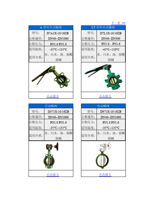
手动蝶阀 型号: D371X-10/16ZB 公称通径: DNห้องสมุดไป่ตู้0--DN1000 公称压力: PN1.0 PN1.6 适用温度: -35°C--135°C
水、污水、油、弱酸 适用介质:
弱碱
点击放大
电动蝶阀 型号: D971X-10/16ZB 公称通径: DN40--DN1000 公称压力: PN1.0 PN1.6 适用温度: -35°C--135°C
点击放大
对夹式蝶型止回阀 型号:H77X-10/16 公称通径:DN50—DN700 公称压力:PN1.0 、 PN1.6 适用温度:-15°C --150°C
蒸汽、污水、淡水、 适用介质:
油类、食品、药品
点击放大
法兰式消声止回阀 型号:H41X/T-10/16 公称通径:DN150-DN400 公称压力:PN1.0、PN1.6 适用温度:0°C --80°C
淡水、污水、海水、 适用介质:
空气
点击放大
点击放大
大口径单偏心法兰蝶阀
型号:D342X-2.5/6/10 公称通径:DN1400—DN2800
PN0.25 、 PN0.6 、 公称压力:
哈威主动式液压站操作与维护手册

阀门产品样本国标安全阀

阀门产品样本罗浮阀门集团有限公司目录1、A21型PN16~40外螺纹连接弹簧封闭微启式安全阀 (1)2、A21型PN64~100外螺纹连接弹簧封闭微启式安全阀 (2)3、A21型PN160~320外螺纹连接弹簧封闭微启式安全阀 (3)4、A27H-10、A27H-16型外螺纹连接弹簧带扳手微启式安全阀 (4)5、A28H型PN16外螺纹连接弹簧带扳手全启式安全阀 (5)6、A37H、A43H型PN16~40双联弹簧带扳手微启式安全阀 (6)7、A38Y型PN16~40双联弹簧带扳手全启式安全阀 (8)8、A40Y型PN16~64带散热片弹簧封闭全启式安全阀 (10)9、A41H、A41Y型PN16~100弹簧封闭微启式安全阀 (12)10、A41Y型PN160~320弹簧封闭微启式安全阀 (15)11、A42F 、A42Y、KA42Y(抗硫)型PN16~100弹簧封闭全启式安全阀 (17)12、42Y型PN160~320弹簧封闭全启式安全阀 (21)13、WA42Y型PN16~40波纹管弹簧全启式安全阀 (22)14、A44Y型PN16~100弹簧封闭带扳手全启式安全阀 (22)15、A44Y型PN160~320弹簧封闭带扳手全启式安全阀 (26)16、A47H型PN16~40弹簧带扳手微启式安全阀 (27)17、A48Y型PN16~100弹簧带扳手全启式安全阀 (29)18、A48SH型PN16~40弹簧带扳手全启式安全阀 (32)19、A48SH型PN64~160高温高压弹簧带扳手全启式安全阀 (34)20、A42Y-P5545V、A62Y-P55 140V型气控碟形弹簧安全阀 (36)21、A68Y型对焊连接弹簧全启式安全阀 (37)22、A49H-40型主安全阀及配套GA49H-40型冲量安全阀 (38)23、A49Y-100、A49Y-100V型主安全阀及其配套冲量安全阀 (40)24、A69Y-P54140V型DN100主安全阀及其配套冲量安全阀 (42)25、A69Y-100、A69Y-100V型DN150主安全阀及其配套冲量安全阀 (43)26、GA41H型PN16~40杠杆式安全阀 (44)27、GA42H型PN16~100单杠杆式安全阀 (45)28、GA44H型PN16~64双杠杆式安全阀 (47)29、A411F-25、A412F-25、NA42F-25型内装式安全阀 (48)30、JA22H-2.5、JA22W-2.5P型外螺纹连接静重式安全阀 (50)31、FA72W型PN10真空负压安全阀 (51)32、AH42F型平衡式安全回流阀 (52)33、A61型弹簧微启式安全阀 (53)34、AY42H PN400型、LA802Y-600型安全溢流阀 (55)35、石化专用安全阀 (57)36、AQ-20型空压机安全阀 (58)37、LFA46F型先导式安全阀系列 (59)封1、A21型PN16~40外螺纹连接弹簧封闭微启式安全阀使用范围:本产品可用于石油、化工行业。
低温球阀中文样本
质量安全是我们的首要责任
Habonim不仅掌握了精湛的技术,同时在阀门行业内 拥有丰富的经验,因此使我们可以开发出这种独特设 计的低温阀产品。 Habonim低温阀设计的标准配置为防火类型,适用 于各种危险性与非危险性环境。
凸榫与凹槽
低温阀阀体与连接端部
凸榫与凹槽设计通常用于各种防火安全型低温阀产品,在我 们的低温阀系列产品中采用了这种设计。这种独特的迷宫式 设计可确保零泄漏,允许膨胀石墨阀体密封件完全压缩,实 现阀体与端部的紧密接触。
低温阀
阀座和密封
当温度低于-200°C/-328°F时,Habonim建议采用 TFM 1600™或Habonim专用NRG阀座。如果温度更 低,Habonim建议采用PCTFE(KEL-F)阀座。这些 阀座会为客户立即带来实效,包括更低的操作扭矩、更 小的执行器及更有竞争力的产品。 当PCTFE阀座用于高强度17-4PH阀杆(代码M)时必 须采用合适的规格,确保能够承受高工作转矩。石墨/聚 四氟乙烯密封件用于低温系列;PTFE及标准石墨密封 件用于防火应用中。这两种密封件都能够用来提供相同 的阀体/端部密封。
阀门部件,包括阀球、阀杆及初始柔性部分均采用1.5倍额定静压 进行液压测试。然后再拆开阀门,采用超声波浴清洗并去除油 污,使阀非常清洁。所有低温阀在洁净室组装,并采用压力为 80psi的纯氦气进行100%在线测试,以及采用氦探漏仪进行检验 (验收标准为1×10⁻⁵立方厘米/秒)。 测试后,将阀端口密封好,并采用聚乙烯袋逐个密封包装好, 确保将阀门完好送到安装地点。 低温测试:在某些情况下,可能需要进行低温阀测试、低温条 件下的运转试验或燃烧试验。
材质规格 不锈钢ASTMA351 CF8M 不锈钢ASTMA351 CF3M/CF8M 不锈钢ASTMA351 CF8M 不锈钢ASTMA276 316/316L, 17-4PH TFM、NRG、PCTFE 不锈钢ASTMA351CF8M PTFE、石墨 NRG Hermetix™、石墨 不锈钢ASTMB783 316L 不锈钢ASTMA240 430 不锈钢ASTMA240 304 不锈钢ASTMA194 316 不锈钢ASTMA351CF8M 不锈钢ASTM316L 不锈钢AISI 304 不锈钢ASTMA582 303 PTFE、石墨 PTFE 不锈钢lSO4014A2-70 DIN127A2 不锈钢 ISO 4014 A2-70 DIN127A2 不锈钢AISI 316L 不锈钢AISI 302 不锈钢AISI 304 不锈钢ASTMA167 304
K220LS 工程机械用方向控制阀 样本MSG17-8537 CN 派克汉尼汾公司说明书

2工程机械用方向控制阀K220LS样本MSG17-8537/CN派克汉尼汾公司移动液压系统欧洲事业部Borås, Sweden样本布局除一般信息和基本技术数据外,该样本还对K220LS 可配置的选配功能做了描述。
我们可据此对K220LS 进行定制配置,以符合您的需求。
多路阀的每个功能区域都有一个副标题,标题后面附有简短的描述。
如果某个功能区有多个不同的位置,则会在副标题的方括号内标注位置编号,例如[P16]溢流阀。
再接下来是一系列带有代号的选项,例如PA1、Y 以及每个代号的简短描述。
或者是一个或多个压力、流量或电压选项。
位置编号也可参见配置代号报告和备件清单。
第8页的一般液压回路图中展示了K220LS 阀的基本功能区、以及代表这些功能区的条目编号。
多路阀订购方式我们开发并推出了配置K220LS 阀的软件。
这个软件也能给您生成阀技术文档,其中会包含详细的阀代号报告、3D 模型、2D 图纸、备件清单和液压原理图。
软件还会创建一个唯一的ID 号,并印在阀产品标签上。
您的阀配置会保存在我们的数据库中,以便查询服务或重新订购时快速确定。
样本信息销售要约请联系您的派克销售代表,获取详细的“销售要约”。
专业建议,以节约时间和成本我们的工程师经验丰富,他们对不同类型的液压系统及其工作原理都有深入的了解。
他们可随时为您提供专业的建议,按您需要的方式将各种机器功能、控制特性和价格要求完美组合在一起。
建议在项目规划阶段尽早咨询派克,为您设计一个完整的液压系统,使您的机器达到理想的操作和控制特性。
派克保留修改产品的权利,恕不另行通知。
本样本中使用了典型的曲线和图表。
即使样本不断修订和更新,也不可避免存在出错的可能。
请联系派克汉尼汾,了解更多有关产品的详细信息。
3工程机械用方向控制阀K220LS样本MSG17-8537/CN派克汉尼汾公司移动液压系统欧洲事业部Borås, Sweden目录目录页码概述....................................................................................................................4技术数据 ............................................................................................................5[P03-P09]概述 ................................................................................................6-7液压原理图 .....................................................................................................8-9进口片 ..............................................................................................................10[P10-P29] 进口片 .......................................................................................10[P12] 内部先导压力供油 ...........................................................................11[P13] 先导压力...........................................................................................11[P14] 先导过滤器.......................................................................................11[P15] 进口片类型.......................................................................................11[P16] 溢流阀...............................................................................................12[P17] 压力设定...........................................................................................12[P20] 负载信号复制阀芯 ...........................................................................13[P24] 回油口T2 ..........................................................................................14[P25] 回油口T1 ..........................................................................................14[P26] 进油口P1 ..........................................................................................14[P28] 用于先导回路的单独回油口............................................................14出口片 ..............................................................................................................15[P30 - P44] 出口片 .....................................................................................15[P31] 油口 ..................................................................................................15[P32] 进油口P2 ..........................................................................................15[P34] 回油口T3 ..........................................................................................15[P40] 先导回路回油口 ...............................................................................15工作片 ..............................................................................................................16[P45-P89] 工作片 .......................................................................................16[P47] 连接油口...........................................................................................16[P50] 阀芯执行器.......................................................................................17PC/PCH 液压阀芯执行器 .....................................................................17ECS2/EC2/ECH2 电液阀芯执行器 .......................................................18[P51] 手柄支架...........................................................................................19[55A, B] 先导节流口...................................................................................20[P56] 插头类型...........................................................................................20[P59] 阀芯执行器变型 ...............................................................................20[P60-P74] 阀芯选择 ...................................................................................21[P60] 阀芯功能...........................................................................................21[P64A, B] 力反馈 ........................................................................................22[P66] 压力补偿器和负载保持单向阀........................................................23[P69] 阀芯名称...........................................................................................24[P71A, B] 工作油口公称流量.....................................................................24[P72] 流量设定...........................................................................................24[P74] 工作片变型.......................................................................................24[P75] 进给减压阀.......................................................................................25[P75A] [P75B] 设定油口A 和B 的进给减压 ................................................25[P76A, B] 溢流阀和防气穴阀.....................................................................26[P85] 侧油口连接.......................................................................................26[P89A, B] 工作油口变型 ............................................................................26[P90-P99] 功能阀块 ...................................................................................27附件 ............................................................................................................27信息..................................................................................................................28[P50] EC2 手动越权 ...................................................................................28尺寸图 ..............................................................................................................29备件..................................................................................................................30[P00]指客户规格中的项目编号。
液压阀样本
液压阀样本----500f39f6-7161-11ec-b616-7cb59b590d7d 最大流量最大使用压力阀孔加工图代码ep08-2a-01-z-04ep08-2a-01-z-05ep10-2a-01-z-05ep12-2a-01-z-05ep16-2a-01-z-05ep19-2a-01-z-05ep17-2a-01-z-05ep21-2a-01-z-05ep20-2a-01-z-05ep13-2a-01-z-05l/min30407015015040701504040l/min20350巴350巴350巴350巴350巴350巴页码12345678910页码11sv-08sv-08sv-10sv-12sv-16o19-eo17-eo21-esv-20t13a阀孔加工图代码最大流量最大使用压力ep08-2a-01-z-052通常闭型附带弹簧最大流量和最大工作压力阀孔加工图代号ep08-2a-01-z-85ep10-2a-01-z-85ep12-2a-01-z-85ep16-2a-01-z-85ep17-2a-01-z-85ep21-2a-01-z-85l/min407015015070150酒吧350350350页码121314151617sv-08sv-10sv-12sv-16o17-eo21-eep08-x-y-z-04扭矩3-4牛米例如:ep08-2a-01-n-04例如:ep08-2a-01-m-04COELEC-04w6662hex.22.2torque25-35nm3/4"-16unf-2a228最大额定压力:最大额定流量:塞孔代码:35030sv-0825-350.13巴尔/明姆克安装扭矩:重量:工作温度:内部泄漏:-40~120℃0.15cc/min(3滴/分)在最大压力350bar时25um或者更好90%额定电压滤波精度:最低电压要求:103040压力-p(巴)121086420线圈必须单独订购。
哈威多路阀E7700-3-GB
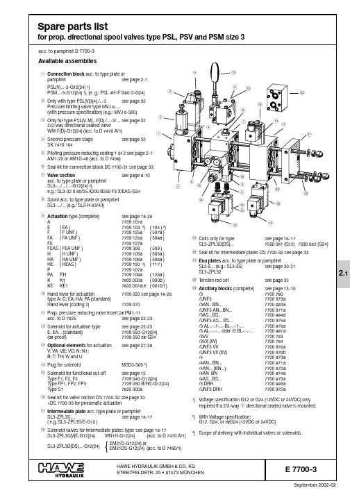
September 2002-02E 7700-3 page 2E 7700-3 page 3E 7700-3 page 4E 7700-3 page 5Connection blocksNote: There is a minimum order value requirement, when ordering spares !Please specify the complete order coding and part No. when ordering spare parts. Subject to change without notice !Order coding NomenclaturePart No.Item111Connection block 7778 06811Connection block 7778 060/111Connection block 7778 070111Connection block 7778 56611111111Bolt ( standard )7778 015a 2or or or Bolt for coding H 7778 015b 21111111Spring ( standard )7650 0113or or or Spring for coding H7778 03431111111Controller piston (complete)7778 04041111111Screw7620 041/151111111Type plate dep. on type ( exact spec. is required )64444444Grooved drive stud ISO 8746-2,3x4-A272222222Seal ring DIN 7603-A4x8x1-Cu82222222Hexagon head screw ISO 4017-M4x6-A2-709or or or or or or or Directional seated valve type WN1 F for coding F acc. to D 7470 A/110or or or or or or orDirectional seated valve type WN1 D for coding D acc. to D 7470 A/1101111Screw 6380 013111Screw 6380 0131211Screw6380 01312a1111Carburetor jet M4/0.612a111Filter screw7807 02412b111111Skt.-head screw ISO 4762-M8x10-A2-70131111111Valve taper 7700 057/1141111111Spring 7700 0511********Screw7700 058161111111Hexagon nut ISO 4035-B M8x1-A2-70171111111Cap nut7700 054181111111Sleeve, (complete)7625 110191111111Screw, (complete)7625 17220or or or or or or or Pressure reducing valve (complete) type AM1-20 for coding 1acc. to D 745821or or or or or or orPressure reducing valve (complete) type AM1D-40 for coding 2acc. to D 74582111111Gap type filter at port M for coding 1or 27778 048/12211Gap type filter at port M for coding 1or 27778 5482213334Tapped plug (DIN 908)-G1/4 A NBR, complet with elastic seal6013 25062334Tapped plug SAE 090 109B-4 SAE HOLLOW HEX PLUG including 6013 251323O-ring AC0-568-9041111111Pre-load and dampening valve (complete) for PSV coding S 7778 30124standard with PSL and PSMor or or or or or Dampening valve (complete) for coding G 7778 30324or or orScrew for coding B 7778 06225or orScrew7778 08026orTapped plug7778 036261Piston for coding U ; UH 7778 014271Spring for coding U ; UH7120 502281Tapped plug for coding U ; UH 7480 033291111111Seal kit DS 7700-31see page 3330-40P S V U N F 44../...-3P S L U N F 4../...-3P S M 5../...-3P S V 55../...-3P S V 45../...-3P S L 5U (U H )../...-3P S L 5../...-3E 7700-3 Seite 6E 7700-3 page 7E 7700-3 page 8E 7700-3 page 9E 7700-3 page 10Order coding NomenclaturePart No .Item 1111Lever housing (complete)dep. on type1incl. shaft and linkage ( not indiv. available )4444Skt.-head screw ISO 4762-M5x50-A2-7022222Back-up ring 7709 00932222Back-up ring 7709 01742222Washer7709 00751111Circlip DIN 6799-96or or or or Circlip DIN 6799-9-1.4122 ( stainless ) for coding S 61111Cap ( stainless )7709 01871111Strainer ( stainless )7709 01981111Lever bracket7709 00892222Grub screw ( stainless ) ISO 4026-M6x6-A2-70102222Grub screw ( stainless ) ISO 4026-M6x16-A2-70111111Pin ISO 8748-5x20-St1211Lever (complete) ( standard )7709 02013or or Lever (complete)for coding 27709 070131111Bolt7709 004142222Circlip DIN 6799-3.2151111Spacer7709 0031611Spring cap (complete)7709 0241711Spring7709 0311811Spring cap (complete)7709 0251911Detent (complete)7709 039201111Washer7709 029211111Flat head screw DIN 7991-M6x35-8.8221111Spring dome7709 021/1231111Retainer for coding G7709 04823a4444Skt.-head screw ISO 4762-M5x8- A2-7024or or or or Skt.-head screw ISO 4762-M5x16-12.9-zinc plated for coding G 24a1111Seal kit DS 7700-32see page 3343, 44, and 50C 1..C S 1..C ..;C S ..A 1..;A S 1..A ..;A S ..Manual actuation type A, AS, A1, and AS1C, CS, C1, and CS1Note: There is a minimum order value requirement, when ordering spares !Please specify the complete order coding and part No. when ordering spare parts. Subject to change without notice !Electro-hydraulic actuation Type E, EA., EC, and EAC.Order coding NomenclaturePart No.Item 11Lever housing (complete) dep. on type 1For spare parts, see page 18-1911Housing7709 013211Bearing needle DIN 5402-2.5x23.8 2.12Grub screw ISO 4026-M6x20-45 H 32Hexagon nut ISO 4035-M6-A2-7042Cap nut7450 022544Skt.-head screw ISO 4762-M5x40-A2-7061Hexagon head screw ISO 4017-M6x6-A2-70711Spacer7709 003822Blanking screw including ( applies only to E0A and E0AC ):7709 0479O-ring 12.42x1.78 HNBR 90Sh and O-ring 9x1.5 NBR 90Sh and Seal ring 7625 109/12222Prop. pressure reducing valve insert type PM1-11 including 7625 150e10O-ring 8x1.5 NBR 90Sh and (55)Seal ring 7625 109/1(56)1111Twin solenoid ( 12V DC )7709 050-G1211or Twin solenoid ( 24V DC )7709 050-G2411or Ex-proof version ( 24V DC,EEX m 120 T4 )7709 050 ex-G24113333Skt.-head screw ISO 4762-M5x50-A2-70121111Plug MSD3-3091311O-ring 10.82x1.78 HNBR 90Sh 1411Detent (complete)7709 1741511Washer7709 1731611Circlip DIN 472-32x1.51711Spring cap with 7709 02618Sleeve 7709 02811Spring cap 7709 0241811Spring 7709 0301911Spring 7709 0311911Spring7709 0312011Spring cap with 7709 02721Sleeve 7709 02811Spring cap 7709 025211111Washer7709 0292211Flat head screw DIN 7991-M6x35-8.82311Flat head screw DIN 7991-M6x75-8.8231Spring dome 7709 022/1241Spring dome 7709 021/12411Housing7709 1712411Flange for coding G7709 04824a 44Skt.-head screw ISO 4762-M5x8-A2-702544Skt.-head screw ISO 4762-M5x10-A2-702544Skt.-head screw ISO 4762-M5x16-12.9 zinc plated for coding G 25a 11Tapped plug including elastic seal 7758 220261111Seal kit DS 7700-32see page 3337a-51E E A E C E A CNote: There is a minimum order value requirement, when ordering spares !Please specify the complete order coding and part No. when ordering spare parts. Subject to change without notice !P HP APOrder coding NomenclaturePart No.Item 1Housing 7709 082111Housing7709 09211Lever housing (complete)dep. on type 2For spare parts, see page 18-191Housing7709 0742Indiv. available components:2Circlip DIN 6799-3,2 2.11Bolt7709 0042.21Seal ring DIN 7603-A4x8x1-Cu31Hexagon head screw ISO 4017-M4x6-A2-7041Screw7700 60651O-ring 28.3x1.78 NBR 90Sh 61Piston 7709 075712Cap nut7450 022812Hexagon nut ISO 4035-M6-A2-70912Grub screw ISO 4026-M6x20-45 H104Skt.-head screw ISO 4762-M5x80-A2-701144Tension rod DIN 940-M5x125-8.8-A2K 1144Cap nut DIN 1587-M5-A2K121Hexagon nut ISO 4035-M6-A2-701311Sleeve (complete)7709 09614with O-ring 7.65x1.78 NBR 70Sh (65)1Piston 7709 0841511Piston7709 0941511Roll pin ISO 8748-2x14-St 1611Rod guide (complete)7709 08317with O-ring 7.65x1.78 NBR 70Sh (65)with O-ring 26.64x2.62 NBR 90Sh (66)1Rod guide (complete)7709 09317with O-ring 7.65x1.78 NBR 70Sh (65)with O-ring 26.64x2.62 NBR 90Sh (66)1Rod 7709 085181Rod 7709 095181Rod 7709 07618111Bolt7709 00419222Circlip DIN 6799-3.2201Spacer including bearing needle DIN 5402-2x9,87709 081211Spacer7709 087211Spacer including bearing DIN 5402-2x9,87709 0872111O-ring (69)211Spacer7709 003222Blanking screw (complete) with type E0 with 7709 04723O-ring 9x1.5 NBR 90Sh withO-ring 12.42x1.78 HNBR 90Sh and Seal ring 7625 109/1111Spring cap including 7709 02624Sleeve 7709 028111Spring 7709 03025111Spring7709 03126111Spring cap including 7709 02727Sleeve 7709 028111Washer7709 02928111Flat head screw DIN 7991-M6x35-8.82911Spring dome 7709 022/1301Spring dome7709 021/130111Flange for coding G7709 04830a 444Skt.-head screw ISO 4762-M5x8-A2-7031or Skt.-head screw ISO 4762-M5x16-12.9 zinc plated for coding G 31a 111Seal kit DS 7700-32see page 3337a-43111Seal kit DS 7700-33see page 3364-69Pneumatic actuation Type P , PA, and PHNote: There is a minimum order value requirement, when ordering spares !Please specify the complete order coding and part No. when ordering spare parts. Subject to change without notice !E 7700-3 page 31End platesOrder coding NomenclaturePart No.Item 1End plate (complete)7778 121/1a 1or End plate UNF (complete)7778 521a 11End plate (complete)7778 121/1c 11End plate (complete)7778 121/1e 11End plate (complete)7778 121/1b 1or End plate UNF (complete)7778 531b 11End plate (complete)7778 121/1d 11End plate (complete)7778 121/1f 11End plate (complete)7778 129a 1or End plate UNF (complete)7778 529a 11End plate (complete)7778 129b 1or End plate UNF (complete)7778 529b 11End plate (complete)7778 129c 1or End plate UNF (complete)7778 529c 11End plate, complete 7778 129d 1orEnd plate UNF (complete)7778 529d 11Intermediate plate (complete)7778 0791Indiv. available components:1111End plate 7778 0811a 11End plate 7778 033/11a 1111End plate 7778 0431a 11End plate UNF 7778 5311a 1111End plate UNF 7778 5431a 11Grub screw ISO 4026-M4x4-22H 211Grub screw ISO 4026-M5x5-45H211111Check valve insert type RC1 (complete)acc. to D 6969 R 3111Check valve insert type RB0(complete)with UNF acc. to D 6969 R 31211121Tapped plug including 6013 25064elastic seal DIN 908-G 1/4 A1211Tapped plug (complete)SAE 0901B-4 with4O-ring HOLLOW HEX PLUG and O-ring AC0-568-90411111Ball DIN 5401-7 G10511111Threaded disc 7271 2346111Threaded disc with UNF 7778 53461111Seal ring DIN 7603-Cu-A5x7.5x171111Skt.-head Screw ISO 4762-M5x6-A2-7081111Filter cap, not available with UNF ports 6406 02191111Fine filter, not available with UNF ports 6406 016101111Filter, not available with UNF ports 7245 0211111Directional seated valve type WN1H-G..acc. to D 7470 A/1123333333333Tension rod type E1-E6and E17-E20 see page 3313a-16b 33O-ring see seal kit DS 7700-31page 333522Ring see seal kit DS 7700-31page 3335a 1Seal kit DS 7700-21see page 3370-72E 20 ( U NF )E 19 ( U NF )E 18 ( U NF )E 17 ( U NF )E 6E 5E 4 ( U NF )E 3E 2E 1 ( U NF )Z P L 32Note: There is a minimum order value requirement, when ordering spares !Please specify the complete order coding and part No. when ordering spare parts. Subject to change without notice !E 7700-3 page 32Order coding NomenclaturePart No.Item 11Spring dome 7186 051/111Screw 7184 037d 2or Screw7184 037a1Hexagon nut ISO 4032-M8-A2-703x xSpacer:40.5 mm thick 5585 023b 1 mm thick 5585 023e 1.5 mm thick5585 023c 2 mm thick5585 023f 11Seal ring 7186 053511Nippel 7186 040611Spring ...80 bar 7000 646/17or or Spring ...160 bar 7000 647/17or or Spring ...315 bar 7000 649/17or or Spring ...500 bar 2564 005a 711Washer 7186 052811Spring guide 7186 054911Dampening piston (complete)7186 07510Indiv. available components:11Spring 7186 05510.111Spring 7000 67310.211Sleeve 7000 67210.31Screw 7184 009111Winged nut 7000 436121Turn knob 7000 411/1131Pin ISO 8748-3x161411Seal kit DS 7700-31see page 3342a+bM V J 6...RM V J 6...Corresponding tothe respectivepressure setting Order coding Nomenclature Part No.Item1Directional seated valve type WN1F or WN1Dacc. to D 7470 A/11with 4x Skt.-head screw ISO 4762-M4x70-12.9 zinc plated 1 a for version with second pressure stage:with 4x Skt.-head screw ISO 4762-M4x85-12.9 zinc plated 1 a 1Intermediate plate (complete)7470 06323Ring 6540 049(35a)1Grooved drive stud ISO 8741-2.5x831Cap nut 7700 05441Hexagon nut ISO 4035-B-M8x1-A2-7051Screw 7700 05861Spring 7700 05171Valve taper 7700 057/181Seal kit DS 7700-31see page 3335 and 37Directional seated valve type WN1F(D)Order example:PSL 3 F /350-3-G.. (as idle circulation valve Emergency Stop)PSL 3 F80/350-3-G.. (with second pressure stage)1a Max.torque 4 Nm1437537678235a35335a 35Pressure limiting valve type MVJ 6Order example:PSL 3/400-3PSV 3/320-3Max.torque 100 Nm2341542a 67891010.110.210.342b141312411Items 2-9 and 35-37intermediateplate (complete)acc. to Sk 7470 104Note: There is a minimum order value requirement, when ordering spares !Please specify the complete order coding and part No. when ordering spare parts. Subject to change without notice !E 7700-3 page 33 Tension rod:Seal kit :DS7700-31(Connection block)Nomenclature Part No.Item1Seal ring DIN 7603-Cu-A6x10x1221Seal ring DIN7603-Cu-A5x9x1242O-ring 14x1.78 HNBR 90 Sh302O-ring 17.12x2.62 HNBR 90 Sh311O-ring 17.17x1.78 HNBR 90 Sh321O-ring 13.94x2.62 HNBR90 Sh32a5O-ring 4.47x1.78 HNBR 90 Sh331Seal ring DIN 7603-Cu-A10x14x1,5343O-ring 6x1.5 NBR90 Sh353Ring6540 04935a1Ermeto ED22x1.5364Seal ring DIN 7603-Cu-A8x12x2371Seal ring7625 109/1381O-ring 9x1.5 NBR90 Sh391Fitting seal DRV 100116-NB 650401O-ring 23.52x1.78 HNBR 90 Sh42a1O-ring 15x2 HNBR90 Sh42bSeal kit:DS7700-33(additionally for version with pneumatic actuation) Nomenclature Part No.Item 1O-ring 25.07x2.62 NBR70 Sh64 4O-ring 7.65x1.78 NBR70 Sh65 1O-ring 26.64,x2.62 NBR90 Sh66 1O-ring 25.07x2.62 NBR90 Sh67 1O-ring 7.65x1.78 NBR90 Sh68 1O-ring 4.47x1.78 HNBR90 Sh69Seal kit:DS7700-22(for intermediate plate type ZPL32)Nomenclature Part No.Item 1O-ring 12.42x1.78 HNBR90 Sh70 3O-ring 10.82x1.78 HNBR90 Sh71 4O-ring 2.90x1.78 HNBR90 Sh72 Seal kit:DS7700-32(Spool valve section)Nomenclature Part No.Item 2Seal ring DIN 7603-Cu-A16.7x22x211 2O-ring 14x1.78 HNBR 90 Sh30 1O-ring 17.12x2.62 HNBR 90 Sh31 1O-ring 17.17x1.78 HNBR 90 Sh32 1O-ring 13.94x2.62 HNBR90 Sh32a 4O-ring 4.47x1.78 HNBR 90 Sh33 2Seal ring DIN 7603-Cu-A10x14x1.534 2Seal ring DIN 7603-Cu-A8x12x237 4Seal ring DIN7603-Cu-A6x10x137a 1O-ring 13x1.5 HNBR 90 Sh41 1O-ring 34.65x1.78 HNBR 90 Sh43 2O-ring 12.42x1.78 HNBR 70 Sh44 2O-ring 36.17x2.62 HNBR 90 Sh50 2O-ring 12.42x1.78 HNBR90 Sh51 2O-ring 3x1.5 NBR90 Sh52 2O-ring 6.86x1.78 HNBR90 Sh53 1O-ring 6.07x1.78 HNBR 90 Sh54 2O-ring 8x1.5 NBR 90 Sh55 2Seal ring7625 109/156 2O-ring 23.47x2.62 NBR 90Sh57Seal kits:Number of added-on valve sectionsEnd plate2 Tension rod M10x... Part No. 7778 910type Item1234567891011121314152 Skt.-head screwISO 4762-M10x80-A2-70145195245293343393442490540590640690740790E1-E613a ISO 4762-M10x100-A2-70165215263313363412460510560610660710758807E17-E2013a ISO 4762-M10x70-A2-70135185235285332380435480533ZPL3213a 1 Skt.-head screw 1 Tension rod M8x... Part No. 7778 908ISO 4762-M8x80-A2-70140190240288337387436486535585635685733783E1-E613b ISO 4762-M8x100-A2-701602102603083574074565ß6555605655705753803E17-E2013b ISO 4762-M8x70-A2-70135185232280330380430480530ZPL3213b2 Washer ISO 7089-10,5-300 HV-A214a1 Washer ISO 7089-8,4-300 HV-A214b-- 2 Hexagon nuts ISO 4032-M10-A2-70-A2K15a -- 1 Hexagon nut ISO 4032-M8-A2-70-A2K15b -- 2 KORREX protective cap M10 NR.610 black16a -- 1 KORREX protective cap M8 NR.608/13 black16bNote: There is a minimum order value requirement, when ordering spares !Please specify the complete order coding and part No. when ordering spare parts. Subject to change without notice !。
哈威多路比例阀样本
U
Automatic reduction of the pump idle circulation pressure by means of a by-pass valve (only type PSL), see also
note in sect. 7.1 a
H
Raised circulation pressure of the 3-way flow controller (approx. 14 bar, type PSL)
? Optional 2/2-way solenoid valve for arbitrary idle pump circulation (see table 9, sect. 3.1.4)
(no coding)
Without directional valve, but prepared for retrofitting
functional cut-off
• Actuation mode
End plate
Selection:
Completion of the valve bank (select acc. to sect. 3.1.5)
• With internal rooting or port T for the return flow of the control oil • With or without additional inlet port LS • Adapter plate for direct mounting of size 3 (valve banks)
@ Tool adjustable, piloted pressure limiting valve (main pressure limitation) in the connection block (see sect. 3.1.4, table 10)
德国哈威HAWE压力限制阀一种小流量限制阀它是在进水腔和出水腔
德国哈威HAWE压力限制阀一种小流量限制阀。
它是在进水腔和出水腔之间设置限流装置,在工作腔和出水腔之间设置导流装置,当流量大于限定值时,本小流量限制阀自动打开,当流量小于或等于限定值时,本小流量限制阀自动关闭。
德国哈威HAWE压力限制阀一种小流量限制阀,包括工作腔、进水腔、出水腔、阀体、阀盖、阀杆,其特征是:本小流量限制阀设有限流装置和导流装置,限流装置位于进水腔和出水腔之间,与阀体连接,导流装置位于工作腔和出水腔之间,与阀体连接或与限流装置连接。
换向阀节流止回阀压力限制阀压力限制阀流量控制阀压力开关HAWE/哈威平衡阀,HAWE/哈威减压阀,HAWE/哈威溢流阀,HAWE/哈威单向阀,HAWE/哈威多路阀,HAWE/哈威换向阀,HAWE/哈威球阀,HAWE/哈威压力阀,HAWE/哈威比例阀,HAWE/哈威调速阀,HAWE/哈威液压阀,HAWE/哈威液控单向阀,HAWE/哈威压力继电器,哈威蓄能器,HAWE/哈威柱塞泵,HAWE/哈威齿轮泵,HAWE/哈威泵站,HAWE/哈威液压泵,AWE/哈威电控手柄,HAWE/哈威液压元件比例多路阀PSV3/220-3-32L40/40/C-A2H40/40A70/C/3BL-0-B7/150-E4比例多路阀PSV551/160-3-42L80/63/EA -E4-G24比例阀放大器EV1M2-12/24,EV22K2-12/24,EV 1 G 1-12/24,EVE3R-G24-1/2,EV 22 K 1-24, EV 1 M 2-12/24,PDMP22-41/G24,EM 11 D-G 24,EM 41 V-1-G 24,EM11S-X205,EM21V-1/2 ,EM21V-G24比例溢流阀PMVP 4-42/G 24,PMVP 65-42/G 24,PMV62-41/G24,PMVP 4-42/G 24,PMVP 4-44/G 24,PMVP 5-43/G 24,PMVP 6-44/G 24,PMVP 65-42/G 24,PMVP4-41/24,PMVP4-41/G24,PMVP452-42/G24ex充液阀 F 63-30,F125-60,F160-76单向阀 B 1-1,B 1-2,B 1-3,B 2-1,B 2-2,B 2-3,B2-4,B2-5,B 2-6-PYD,B 2-7,B 2-7-PYD,B 3-1,B 3-2,B 3-3,B 3-4,B 3-5,B3-5,ER 21,F 63,ER 21,PK 1,RB 2,RB 4 G-PYD,RK 2,PK 47,RB 14,RB 2,RB 2,RB 28,RB 32,RB 4 G-PYD,RB 47。
哈电超临界阀门选型手册

当介质最高温度>450℃时,标注工作温度和工作压力,工作压力需用 P 标
识并在 P 字的右下角附加介质最高温度数字。该数字是以 10 除介质最高温度数
值所得的整数。如:工作温度为 540℃,工作压力为 10MPa 的阀门,其代号为
PW5410V,
8. 阀体材料代号用汉语拼音字母表示:
(表 6)
代 号
1
3
4
5
6
7
9
蝶 阀 结 构 形 式
C 代 号
(表 4-3)
杠 杆 式 垂直板式 斜 板 式 减压阀结构形式 薄膜式 弹簧薄膜式 活塞式
0
1
3
代 号 1
2
3
(表 4-4)
波纹管式 杠杆式
4
5
(表 4- 5)
C (圈)
50
转速 24
( r/min)
电机功率 0.37
( kw)
扬州电力设备修造厂电动装置详表
DZW30 DZW30(I)
DZW45
DZW60
DZW90 DZW90(I)
DZW120 DZW120(I)
DZW180 DZW500
300
450 600
900
1200
1800
5000
50
120 120
7
封
闭
全 启 式
8
带控制机构 全 启 式
6
先 导 式
9
全 启 式
2
杠
单 杠 杆
角形微启式
5
杆
双 杠 杆
全 启 式
4
套 筒 式
Moog Inc. X77XK系列工业伺服阀安装、操作和故障排除手册说明书
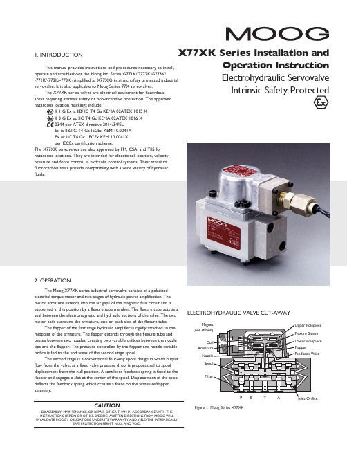
P B T AELECTROHYDRAULIC VALVE CUT-AWAYINSTRUCTIONS HEREIN OR OTHER SPECIFIC WRITTEN DIRECTIONS FROM MOOG WILLINVALIDATE MOOG’S OBLIGATIONS UNDER ITS WARRANTY AND YIELD THE INTRINSICALLYSAFE PROTECTION PERMIT NULL AND VOID. Upper PolepieceFlexure SleeveLower Polepiece Flapper Feedback WireInlet OrificeMagnet(not shown)CoilArmatureNozzleSpoolFilterFigure 1 Moog Series X77XKP B T AInput signal induces a magnetic charge in the armature and causes a deflection of the armature and flapper. This assembly pivots about the flexure tube and increases the size of one nozzle orifice and decreases the size of the other. This action creates a differential pressure from one end of the spool to the other and results in spool displacement. The spool displacement transmits a force to the feedback wire which opposes the original input signal torque. Spool movement continues until the feedback wire force equals the input signal force. 3. ELECTRICAL INFORMATION AND INTRINSICALLY SAFE CIRCUIT SAFETY PARAMETERSa.A wide choice of coils is available for a variety of rated currentrequirements. The torque motor coil leads are attached to the connector so external connections can provide series, parallel or single coiloperation. The valves are equipped either with an MS type connector or with pigtail leads for electrical wiring. Refer to installation drawings of the specific model for details. Servovalve coils should be driven with current to provide consistency throughout the temperature range.b.The X77XK valves are approved for intrinsically safe protection per EN IEC 60079-0 : 2018, EN 60079-7 : 2015, and EN 60079-11 : 2012 for ATEX, and IEC 60079-0 : 2017, IEC 60079-7 : 2017, and IEC 60079-11 : 2011 for IECEx. The approved safety parameters are listed in the following table for all the coils used by X77XK series. Coil number is marked on thevalve nameplate.Coil Configuration EX Marking U i (MAX) I i (MAX)G4220-031 (single, series, parallel) Ex ia IIB T4 12 V 120 mAG4220-051/098 (single, series, parallel) Ex ia IIB T4 12 V 240 mA G4221-001 G4220-042 (single) Ex ia IIC T4 16 V 160 mA G4221-001 G4220-042 (single) Ex ia IIC T4 24.4 V 85 mA G4220-031 (single, parallel) Ex ia IIC T4 30 V 26 mA G4220-031 (series) Ex ia IIC T4 30 V 18 mA G4220-051/098 (single, parallel) Ex ia IIC T4 30 V 19 mA G4220-051/098 (series) Ex ia IIC T4 30 V 12.7 mA G4220-042 (single) Ex ia IIC T4 30 V 37 mA G4220-042 (parallel) Ex ia IIC T4 30 V 20 mA G4220-042 (series) Ex ia IIC T4 30 V 10 mA G4221-001 (single) Ex ia IIC T4 30 V 28 mAc.The X77XK valves are approved for non-incendive operation for supply current not to exceed 50 mA dc.d.When making electric connections to the valve, appropriate measures must be taken to ensure that locally different earth potential do not result in excessive ground currents. When barriers are required for the hazardous location, hazardous area (field) wiring must meet the requirements of the barrier manufacturer. All barriers must be mounted and installed in compliance with the barrier manufacturer’s requirements. Twisted pairs of 18-20 gage wire are recommended. If shielded wire is used, connect shield wire to earth ground only at the barrier strip.4. SPECIAL CONDITIONS FOR SAFE USE Because the enclosure of the apparatus is made of aluminum, if it ismounted in an area where the use of category 1 G apparatus is required, it must be installed such that even in the event of rare incidents, ignition sources due to impact and friction sparks are excluded. When the electrohydraulic servovalve is used in an application for type of explosion protection intrinsic safety “i”, the appropriate box on the data label must be scored. When the electrohydraulic servovalve is used in an application for type of explosion protection “n”, the appropriate box on the data label must be scored. After use in an application for type of explosion protection “n”, the servovalve cannot abe safely used in a intrinsically safe application. The screwed cable connector may only be disconnected when the circuit is de-energized or when the location is known to be non-hazardous. When used at an ambient temperature ≥70°C, heat resistant cable must be used with a continuous operating temperature in accordance with the application.When the electrohydraulic servovalve is used in type of protection “n” or “ec”, the equipment shall only be used in an area of not more than Pollution Degree 2, as defined in IEC 60664-1. The cable gland shall be installed such that impact is not possible. When the electrohydraulic servovalve is used in type of protection “n” or “ec”, the user shall provide additional clamping of the cable to ensure that pulling is not transmitted to the terminations.5. HYDRAULIC SYSTEM PREPARATIONTo prolong servovalve operational life and to reduce hydraulic system maintenance, it is recommended that the hydraulic fluid be kept at a cleanliness level of ISO DIS 4406 Code 16/13 maximum, 14/11 recommended. The most effective filtration scheme incorporates the use of a kidney loop or “off-line” filtration as one of the major filtration components. The filter for the “off-line” filtration scheme should be a ß3≥75 filter for maximum effectiveness. Upon system startup and prior to mounting the servovalve, the entire hydraulic system should be purged of built-in contaminating particles by an adequate flushing. The servovalve should be replaced by a flushing manifold and the hydraulic circuit powered up under conditions of fluid temperature and fluid velocity, reasonably simulating normal operating conditions. New system filters are installed during the flushing process whenever the pressure drop across the filter element becomes excessive. The flushing processes should turn over the fluid in the reservoir between fifty to one hundred times. To maintain a clean hydraulic system, the filters must be replaced on a periodic basis. It is best to monitor the pressure drop across the filter assembly and replace the filter element when the pressure drop becomes excessive. In addition to other filters that are installed in the hydraulic circuit, it is recommended that a large capacity, low pressure ß3≥75 filter be installed in the return line. This filter will increase the interval between filter element replacements and greatly reduce the system contamination level.6. INSTALLATIONThe Moog X77XK Series Industrial Servovalve may be mounted in any position, provided the servovalve pressure, piston and return ports match respective manifold ports. The mounting pattern, port location and mounting bolts of the servovalve are shown on Figure 4. Apply a light film of oil to the screw threads and torque to 57 inch-pounds. Wire mating connector for desired coil configuration and polarity. Thread connector to valve.7. MECHANICAL NULL ADJUSTMENTIt is often desirable to adjust the flow null of a servovalve independent of other system parameters. The “mechanical null adjustment” on the Moog X77XK Series servovalve allows at least ±20% adjustment of flow null. The “mechanical null adjustor” is an eccentric bushing retainer pin located above the port designation on the valve body (see Figure 2) which, when rotated, provides control of the bushing position. Mechanical feedback elements position the spool relative to the valve body for a given input signal. Therefore, a movement of the bushing relative to the body changes the flow null.Adjustment ProcedureUsing a 3/8 inch offset box wrench, loosen the self-locking fitting until the null adjustor pin can be rotated. (This should usually be less than 1/2 turn). DO NOT remove self-locking fitting. Insert a 3/32 inch allen wrench in null adjustor pin. Use the 3/32 inch Allen wrench to rotate the mechanical null adjustor pin to obtain desired flow null. Torque self-locking fitting to 57 inch lbs.Note: Clockwise rotation of null adjustor pin produces flow from port P to port B.Figure 2Mechanical Null Adjustment10. FILTER ASSEMBLY REPLACEMENT Tools and Equipmenta. Blade screwdriverb. 3/16Allen wrench c. Torque wrench d. Tweezers a. Remove four socket head cap screws and lockwashers using a Allen wrench. Remove end caps.b. Remove o-rings from end caps.c. Remove inlet orifice assembly from both sides of body. Note: 2-56 screw threads into the inlet orifice assembly.Remove filter. The inlet orifice assemblies are matched to each other and are therefore interchangeable.Note: These assemblies seat in body and cannot go through bore during removal.d. Remove o-rings from inlet orifice assemblies.e. Visually inspect orifice assemblies for damage or foreign material.f. Discard o-rings and filter.g. Install o-rings on inlet orifices.h. Install filter and inlet orifice assembly in body. Inlet orifice assembly pilots End capEnd Cap O-RingsFigure 3FilterInlet Orifice O-Rings (two at each end cap)8. GENERAL SERVICING RECOMMENDATIONSa. Disconnect electrical lead to servovalve.b. Relieve hydraulic system of residual pressure.c.Remove servovalve.TJW/PDF/Rev.G, January 2023, Id. CDS6768-enMoog Inc., East Aurora, NY 14052-0018 Telephone: 716/652-2000Fax: 716/687-7910Toll Free: 1-800-272-MOOG /industrialFigure 4The products described herein are subject to change at any time without notice, including, but not limited to, product features, specifications, and designs.4。
哈威PSV多路阀D7770-cn

具有特殊减振功能
1. 概述
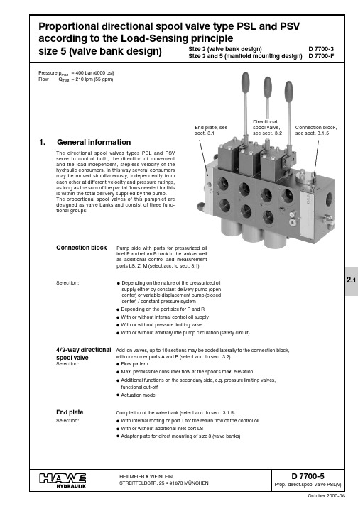
工作压力 Pmax=420bar;流量 Qmax=80l/min
按照工业标准 ISO1219-1,这些阀属于压力阀。它们可以防止牵拉或推压的负载在负载方向运动时失控地加速运动,或者
防止执行元件以高于设定的(泵侧供油决定的)速度运动。因此,这些元件可以防止油柱的断裂或可能发生的破坏。平衡
流量和阻尼孔组 合的代码,见表 2 和表 3。以及资料 B7770 中的功能介 绍
平衡阀的设定压力(bar) 执行元件 V1 侧 执行元件 V2 侧
缓冲阀的设定压力(bar) 执行元件 V1 侧 执行元件 V2 侧
LHDV 33-25- D5-220/220-260/260
带缓冲阀的基本结构形式,例如用于活塞面积比为 1:1 的执行元件。具有附加 泄油口的 LHDV 33-25L 型的图型符号与 LHDV 33-21L…相似。
订货示例:LHDV 33P-15- B 6-300/320
据 3 节,在选定的压力范围内确定设定压力 为了正确地确定平衡阀和缓冲阀的压力值, 请参阅下列示例
表 2 流量匹配
表 3:阻尼孔的组合(阻尼孔-无代码=0.5)
代码
阻尼孔 2
4
5
6
7
(标准的)
Ф(mm) 0.4 0.5
0.6
0.7
开启比 1:6.3 1:4.45 1:2.9 1:1.84
接口
DIN ISO 228/1 (BSPP):
F
=G1/2
M,S,Z =G1/4
LHDV 33P-15 型
下面示出用于管式连接的连
接块!
O 形圈 12.37x2.62NBR 90 Sh
唯一对称膜式阀门DV-ST超级纯净说明书
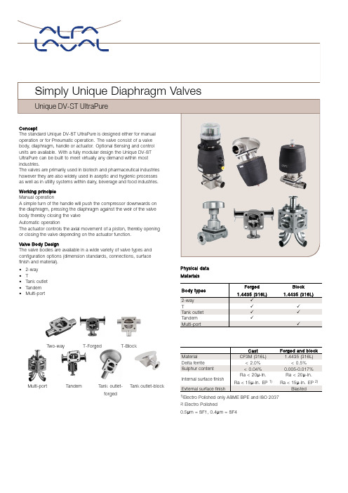
finish and material).•2-way•T•Tank outlet •Tandem•Multi-portTwo-way T-ForgedT-BlockMulti-port Tandem Tank outlet-forgedTank outlet-blockPhysical dataMaterialsBody typesForged1.4435(316L)Block1.4435(316L)2-way✓T✓✓Tank outlet✓✓Tandem✓Multi-port✓Cast Forged and blockMaterial CF3M(316L) 1.4435(316L)Delta ferrite<2.0%<0.5%Sulphur content<0.04%0.005-0.017%Internal surface finishRa<20µ-In.Ra<15µ-In.EP1)Ra<20µ-In.Ra<15µ-In.EP2)External surface finish Blasted1)Electro Polished only ASME BPE and ISO20372)Electro Polished0.5µm=SF1,0.4µm=SF4Sensing and control units:A wide range of sensing and control units are available for actuators consisting of:•Sensing•Controls unit•Indication units•Electrical ATEX units•Stroke limitersDocumentationAll UltraPure valves are delivered with our comprehensive Q-Doc documentation package,which includes:• 3.1/MTR traceability certificate corresponding to EN10204•FDA-Declaration of conformity to FDA(CFR21:177.2600or177.1550)•USP-Certificate of conformity to USP Class VI(Chapter88,biological reactivity test)•TSE/ADI-Declaration(Transmissible Spongiform Encephalopathy/Animal DerivedIngredients)•Surface finish conformity declarationThe following documentation is available upon request:•Surface finish certificate(Ra test results)•ATEX certificateHandle and actuator:The diaphragm valves can be operated by a handle or a pneumatic actuator.Alfa Laval offers4different types of manual handles and3different types of pneumatic actuators.The special design of the actuators enables quick conversion of the control function(NC to Air/Air to NO)and permits adjustment of the spring pressure to optimise the diaphragm life.The handles and actuators are available in different materials:Stainless Steel(SS),Composite(C)and with various features and options.ActuatorsModel SS/SS C/SS C/CSizes1/4”-2”1/4”-3”1/2”-2”Housing Stainless steel PPS/PP-GF1)PPS/PP-GF1) Intermediate part Stainless steel Stainless steel PPS/PP-GF1) Compressor,stem Stainless steel Stainless steel Stainless steelMax.product working pressure145psi145psi145psiMax.air temperature176°F122°F122°FMax.air pressure87psi87psi87psiATEX,Ex II2GDc✓✓Optical positioner✓✓✓Interchangable control function✓✓4)Adjustable spring pressure✓2)✓2)✓2) Autoclavable✓3)✓3)✓3)1)PPS(Polyphenylene sulphide)for sizes up to2"and PP(Polypropylene)with glass fibre or sizes from2½"and up2)Option not available above2".3)249.8°F for max.60min4)NO+A/A actuator in C/C is not possible to mount on PTFE diaphragm.HandlesModel SS/SS SS/SS C/SS C/CSize1/4”-2”2½”-3”1/4”-3”1/2”-2”Handwheel Stainless steel Stainless steel POM2)PPBonnet Stainless steel Stainless steel Stainless steel PPSpindle+compressor1)Stainless steel Stainless steel Stainless steel BrassMax.product pressure145PSI145PSI145PSI145PSI Overclosure protection✓✓✓✓Optical positioner✓✓✓✓Lockable✓Autoclavable✓3)✓3)✓3)✓4)1)For DN65and up,the compressor is nickel plated cast iron2)POM(Polyoxymethylene)3)249.8°F for max.60min.4)Max.working temperature176°FDiaphragmsThe diaphragms are available as soft elastomer(EPDM)as well as hard elastomers(PTFE/EPDM and TFM/EPDM).The hard elastomers are supported by a soft elastomer(EPDM).The 2-piece design allows the two elastomers to work independently of each other,thereby reducing tension caused by different thermal properties.Diaphragms are available with3different types of connections:thread, bayonet and button connection.•Threaded connections are used on soft elastomers≥1"•Bayonet connections are used on all hard elastomer≥1/2"•Button connections are used on all small sizes.Material selection:Each application has different working conditions and therefore different demands on the diaphragm.In order to select the most suitable diaphragm for your application,the following factors should be considered:•Working pressure•Application temperatures•Process fluids(product,cleaning liquid,sterilisation,passivation, etc.)Soft elastomer(EPDM)is suitable for most applications and for high working temperatures.Including continuous steam application.Hard elastomers offer the highest possible degree of chemical resistance.Our TFM(PFTE grade)elastomer is a more flexible material and has some of the features of soft elastomer including for example low creep.For further information,please see below or contact Alfa Laval for further guidance.Diaphragm properties:Temperature recommendations°F Documentation Available sizes Available Diaphragm connections:DescriptionMin.Max.LiquidMax.Steam FDA USP TSE Button Thread BayonetEPDM-40°F266°F302°F1)✓✓✓3”-4”1/4”-3/4”1”-3”PTFE/EPDM23°F347°F302°F2)✓✓✓1/2”-3”½”-3”TFM/EPDM23°F347°F302°F2)✓✓✓3”-4”1/4”-3/8”½”-3”1)Continuous temperature2)40min.steam sterilizationFDA-Declaration of conformity to FDA(CFR21:177.2600or177.1550)USP-Certificate of conformity to USP Class VI(chapter88,biological reactivity test)TSE/ADI Declaration(Transmissible Spongiform Encephalopathy/Animal Derived Ingredients)Pressure drop/capacity tableKv value(Pipe standard ISO420)Lift kv in l/min.∆p=1barin%DN8(1/4”)DN15(1/2”)DN20(3/4”)DN25(1”)DN40(1½”)DN50(2”)DN65(2½”)DN80(3”) 1002770146218684115615712533 902768140210667111614802515 802667133201625107614452462 70256412419461099413652312 60235910116554589312102170 5020478714245775010441925 401835551153456068351565 3011224365310424625845 2010172025180222280401 10257145064125195Kv value(Pipe standard BS O.D.Tubing)Lift kv in l/min.∆p=1barin%DN8(1/4”)DN15(1/2”)DN20(3/4”)DN25(1”)DN40(1½”)DN50(2”)DN65(2½”)DN80(3”) 100 3.435991804269141395206690 3.335991734259141394206680 3.334971554109131393205870 3.333951454019101311203060 3.333941403888821210195050 3.231901053497761090175340 3.1287695335665872144530 3.119656626552563094020 3.010454813937025030010 2.631010226788142Cv=1.16x KvNote!For the diagrams the following applies:Medium:Water(20°C)Measurement:In accordance with VDI2173Drain angle x:Port sizeDN InchASME BPE8¼”37°10⅜”33°15½”32°20¾”26°251”22°401½”24°502”24°652½”20°803”22°2-way bodies:2-way bodies are the standard configuration for shut off and regulating functions.The2-way bodies are available from forged or castmaterial.Weld ends:(in)Port size Length ASME BPE DN Inch L OD x t8¼” 3.500.25x0.03510⅜” 3.500.38x0.03515½” 4.330.50x0.06520¾” 4.680.75x0.065251” 5.08 1.00x0.065401½” 6.34 1.50x0.065502”7.56 2.00x0.065652½”8.58 2.50x0.065803”10.08 3.00x0.065Clamp ends:Port size Length Length Clamp ASME BPE for ASME BPE DN Inch L L11)OD ID8¼” 3.50 2.50.980.18 10⅜” 3.50 2.50.980.31 15½” 4.25 3.50.980.37 20¾” 4.65 4.00.980.62 251” 5.00 4.5 1.980.87 401½” 6.26 5.5 1.98 1.37 502”7.52 6.25 2.52 1.87 652½”8.507.63 3.05 2.37 803”10.008.75 3.58 2.871)ASME BPE Clamp,short versionOther sizes and connections available on request.T-bodies:T are constructed with weir as close as possible to the internal contour of the main tube thereby minimising potential dead leg. The T-bodies are available as machined from block or from forged material.Dimension table for T-forged bodies-ASME BPEMain tube ValveMain tubeOD x tValveOD x tL-WeldL-ClampB-WeldB-ClampCInch Inch in in in in in in in 1/4"1/4"ø0.25x0.04ø0.25x0.04 3.50 2.50 2.07 1.560.1 3/8"1/4"ø0.38x0.04ø0.25x0.04 3.50 2.50 2.13 1.620.14 1/2"1/4"ø0.50x0.06ø0.25x0.04 4.33 3.50 2.17 1.660.11 3/4"1/4"ø0.75x0.06ø0.25x0.04 4.69 4.02 2.30 1.800.24 1"1/4"ø1.00x0.06ø0.25x0.04 5.08 4.49 2.44 1.940.35 1½"1/4"ø1.50x0.06ø0.25x0.04 6.34 5.51 2.52 2.020.61 2"1/4"ø2.00x0.06ø0.25x0.047.56 6.26 2.68 2.180.81 2½"1/4"ø2.50x0.06ø0.25x0.048.587.64 2.95 2.450.933"1/4"ø3.00x0.06ø0.25x0.0410.088.74 3.01 2.51 1.18 3/8"3/8"ø0.38x0.04ø0.38x0.04 3.50 2.50 2.13 1.620.14 1/2"3/8"ø0.50x0.06ø0.38x0.04 4.33 3.50 2.17 1.660.11 3/4"3/8"ø0.75x0.06ø0.38x0.04 4.69 4.02 2.30 1.800.24 1"3/8"ø1.00x0.06ø0.38x0.04 5.08 4.49 2.44 1.940.35 1½"3/8"ø1.50x0.06ø0.38x0.04 6.34 5.51 2.52 2.020.61 2"3/8"ø2.00x0.06ø0.38x0.047.56 6.26 2.68 2.180.81 2½"3/8"ø2.50x0.06ø0.38x0.048.587.64 2.95 2.450.93 3"3/8"ø3.00x0.06ø0.38x0.0410.088.74 3.01 2.51 1.18 1/2"1/2"ø0.50x0.06ø0.50x0.06 4.33 3.50 2.60 2.560.16 3/4"1/2"ø0.75x0.06ø0.50x0.06 4.69 4.02 2.76 2.720.20 1"1/2"ø1.00x0.06ø0.50x0.06 5.08 4.49 2.91 2.870.31 1½"1/2"ø1.50x0.06ø0.50x0.06 6.34 5.51 3.23 3.190.51 2"1/2"ø2.00x0.06ø0.50x0.067.56 6.26 3.50 3.460.63 2½"1/2"ø2.50x0.06ø0.50x0.068.587.64 3.54 3.500.91 3"1/2"ø3.00x0.06ø0.50x0.0610.088.74 3.62 3.58 1.14 3/4"3/4"ø0.75x0.06ø0.75x0.06 4.69 4.02 3.01 2.990.06 1"3/4"ø1.00x0.06ø0.75x0.06 5.08 4.49 3.11 3.090.12 1½"3/4"ø1.50x0.06ø0.75x0.06 6.34 5.51 3.44 3.430.35 2"3/4"ø2.00x0.06ø0.75x0.067.56 6.26 3.72 3.700.49 2½"3/4"ø2.50x0.06ø0.75x0.068.587.64 3.86 3.840.71 3"3/4"ø3.00x0.06ø0.75x0.0610.088.74 3.94 3.920.94 1"1"ø1.00x0.06ø1.00x0.06 5.08 4.49 3.54 3.500.31 1½"1"ø1.50x0.06ø1.00x0.06 6.34 5.51 3.78 3.740.31 2"1"ø2.00x0.06ø1.00x0.067.56 6.26 4.06 4.020.47 2½"1"ø2.50x0.06ø1.00x0.068.587.64 4.33 4.290.59 3"1"ø3.00x0.06ø1.00x0.0610.088.74 4.51 4.470.79 1½"1½"ø1.50x0.06ø1.50x0.06 6.34 5.51 4.72 4.690.45 2"1½"ø2.00x0.06ø1.50x0.067.56 6.26 4.92 4.880.53 2½"1½"ø2.50x0.06ø1.50x0.068.587.64 4.92 4.880.65 3"1½"ø3.00x0.06ø1.50x0.0610.088.74 5.12 5.08 1.02 2"2"ø2.00x0.06ø2.00x0.067.56 6.26 5.71 5.690.51 2½"2"ø2.50x0.06ø2.00x0.068.587.64 5.71 5.690.31 3"2"ø3.00x0.06ø2.00x0.0610.088.74 6.06 6.040.53 2½"2½"ø2.50x0.06ø2.50x0.068.587.64 6.22 6.180.30 3"2½"ø3.00x0.06ø2.50x0.0610.088.74 6.93 6.890.69 3"3"ø3.00x0.06ø3.00x0.0610.088.747.727.680.79Dimension table for T-forged bodies-ISO2037Main tube ValveMain tubeOD x tValveOD x tL-WeldL-ClampB-WeldB-ClampCDN DN in in in in in in in0.590.59ø0.68x0.04ø0.68x0.04 4.33 4.25 2.74 2.70.24 0.790.59ø0.84x0.04ø0.68x0.04 4.69 4.65 2.81 2.780.240.980.59ø0.98x0.05ø0.68x0.04 5.085 2.91 2.870.311.570.59ø1.5x0.05ø0.68x0.04 6.34 6.26 3.23 3.190.511.970.59ø51.0x1.2ø0.68x0.047.567.52 3.5 3.460.632.320.59ø63.5x1.6ø0.68x0.048.588.5 3.54 3.50.913.150.59ø76.1x1.6ø0.68x0.0410.0810 3.62 3.58 1.14 0.790.79ø0.84x0.04ø0.84x0.044.69 4.65 3.07 3.050.10.980.79ø0.98x0.05ø0.84x0.04 5.085 3.11 3.090.121.570.79ø1.5x0.05ø0.84x0.04 6.34 6.26 3.44 3.430.351.970.79ø2.0x0.05ø0.84x0.047.567.523.72 3.70.492.320.79ø2.5x0.06ø0.84x0.048.588.53.86 3.840.713.150.79ø76.1x1.6ø0.84x0.0410.0810 3.94 3.920.940.980.98ø0.98x0.05ø0.98x0.05 5.085 3.54 3.50.311.570.98ø1.5x0.05ø0.98x0.05 6.34 6.26 3.78 3.740.311.970.98ø2.0x0.05ø0.98x0.057.567.52 4.06 4.020.472.320.98ø2.5x0.06ø0.98x0.058.588.5 4.33 4.290.593.150.98ø3.0x0.06ø0.98x0.0510.08104.51 4.470.79 1.57 1.57ø1.5x0.05ø1.5x0.05 6.34 6.26 4.72 4.690.451.97 1.57ø2.0x0.05ø1.5x0.057.567.52 4.92 4.880.532.32 1.57ø2.5x0.06ø1.5x0.058.588.5 4.92 4.880.653.15 1.57ø3.0x0.06ø1.5x0.0510.0810 5.12 5.08 1.021.97 1.97ø2.0x0.05ø2.0x0.057.567.52 5.71 5.690.512.32 1.97ø2.5x0.06ø2.0x0.058.588.5 5.71 5.690.313.15 1.97ø76.1x1.6ø2.0x0.0510.0810 6.06 6.040.532.32 2.32ø2.5x0.06ø2.5x0.068.588.5 6.22 6.180.33.15 2.32ø3.0x0.06ø2.5x0.0610.0810 6.93 6.890.69 3.15 3.15ø3.0x0.06ø3.0x0.0610.08107.727.680.79Main tube ValveMain tubeOD x tValveOD x tL-WeldL-ClampB-WeldB-ClampCDN DN in in in in in in in 0.310.31ø0.39x0.04ø0.39x0.04 3.5 3.5 2.11 2.110.08 0.390.31ø0.51x0.06ø0.39x0.04 3.5 3.5 2.15 2.150.12 0.590.31ø0.75x0.06ø0.39x0.04 4.33 4.25 2.28 2.280.24 0.790.31ø0.91x0.06ø0.39x0.04 4.69 4.65 2.44 2.440.310.980.31ø1.14x0.06ø0.39x0.04 5.085 2.52 2.520.431.260.31ø1.38x0.06ø0.39x0.04 5.0852.68 2.680.47 1.570.31ø1.61x0.06ø0.39x0.04 6.34 6.26 2.8 2.80.551.970.31ø2.09x0.06ø0.39x0.047.567.523.01 3.010.672.560.31ø2.76x0.08ø0.39x0.048.588.53.07 3.07 1.063.150.31ø85.0x2.0ø0.39x0.0410.0810 3.19 3.19 1.38 0.390.39ø0.51x0.06ø13.0x1.5 3.5 3.5 2.15 2.15 1.38 0.590.39ø0.75x0.06ø0.51x0.064.33 4.25 2.28 2.280.24 0.790.39ø0.91x0.06ø0.51x0.06 4.69 4.65 2.44 2.440.310.980.39ø1.14x0.06ø0.51x0.06 5.085 2.52 2.520.431.260.39ø1.38x0.06ø0.51x0.06 5.0852.64 2.640.55 1.570.39ø1.61x0.06ø0.51x0.06 6.34 6.26 2.8 2.80.551.970.39ø2.09x0.06ø0.51x0.067.567.523.01 3.010.672.560.39ø2.76x0.08ø0.51x0.068.588.53.07 3.07 1.063.150.39ø3.35x0.08ø0.51x0.0610.0810 3.19 3.19 1.38 0.590.59ø0.75x0.06ø0.75x0.064.33 4.25 2.72 2.680.2 0.790.59ø0.91x0.06ø0.75x0.06 4.69 4.65 2.83 2.80.280.980.59ø1.14x0.06ø0.75x0.06 5.085 2.99 2.950.391.260.59ø1.38x0.06ø0.75x0.06 5.085 3.11 3.070.47 1.570.59ø1.61x0.06ø0.75x0.06 6.34 6.26 3.23 3.190.591.970.59ø2.09x0.06ø0.75x0.067.567.523.46 3.430.712.560.59ø2.76x0.08ø0.75x0.068.588.53.66 3.62 1.023.150.59ø3.35x0.08ø0.75x0.0610.0810 3.8 3.76 1.32 0.790.79ø0.91x0.06ø0.91x0.064.69 4.65 3.13 3.110.140.980.79ø1.14x0.06ø0.91x0.06 5.085 3.23 3.210.21.260.79ø1.38x0.06ø0.91x0.06 5.085 3.35 3.330.31 1.570.79ø1.61x0.06ø0.91x0.06 6.34 6.26 3.5 3.480.411.970.79ø2.09x0.06ø0.91x0.067.567.523.76 3.740.532.560.79ø2.76x0.08ø0.91x0.068.588.53.98 3.960.833.150.79ø3.35x0.08ø0.91x0.0610.08104.11 4.09 1.120.980.98ø1.14x0.06ø1.14x0.06 5.085 3.62 3.580.281.260.98ø1.38x0.06ø1.14x0.06 5.085 3.74 3.70.31 1.570.98ø1.61x0.06ø1.14x0.06 6.34 6.26 3.9 3.860.351.970.98ø2.09x0.06ø1.14x0.067.567.52 4.13 4.090.512.560.98ø2.76x0.08ø1.14x0.068.588.5 4.45 4.410.713.150.98ø3.35x0.08ø1.14x0.0610.08104.67 4.630.96 1.26 1.26ø1.38x0.06ø1.38x0.065.085 3.74 3.70.31 1.57 1.26ø1.61x0.06ø1.38x0.066.34 6.26 3.9 3.860.351.97 1.26ø2.09x0.06ø1.38x0.067.567.52 4.13 4.090.512.56 1.26ø2.76x0.08ø1.38x0.068.588.5 4.45 4.410.713.15 1.26ø3.35x0.08ø1.38x0.0610.08104.67 4.630.96 1.57 1.57ø1.61x0.06ø1.61x0.06 6.34 6.26 4.72 4.690.451.97 1.57ø2.09x0.06ø1.61x0.067.567.52 4.92 4.880.632.56 1.57ø2.76x0.08ø1.61x0.068.588.5 5.1 5.060.793.15 1.57ø3.35x0.08ø1.61x0.0610.08104.55 4.51 1.221.97 1.97ø2.09x0.06ø2.09x0.067.567.52 5.71 5.690.512.56 1.97ø2.76x0.08ø2.09x0.068.588.5 5.87 5.850.633.15 1.97ø3.35x0.08ø2.09x0.0610.0810 6.26 6.240.712.56 2.56ø2.76x0.08ø2.76x0.088.588.5 6.42 6.380.433.15 2.56ø3.35x0.08ø2.76x0.0810.08107.177.130.87 3.15 3.15ø3.35x0.08ø3.35x0.0810.08107.957.910.94Main tube ValveMain tubeOD x tValveOD x tL-WeldL-ClampB-WeldB-ClampCDN DN in in in in in in in 0.310.31ø0.53x0.063ø0.53x0.063 3.5 3.5 2.2 2.20.24 0.390.31ø0.68x0.063ø0.53x0.063 4.33 4.25 2.26 2.260.24 0.590.31ø0.84x0.063ø0.53x0.063 4.33 4.25 2.32 2.320.28 0.790.31ø1.06x0.063ø0.53x0.063 4.69 4.65 2.5 2.50.390.980.31ø1.33x0.079ø0.53x0.063 5.085 2.62 2.620.451.260.31ø1.67x0.079ø0.53x0.063 6.34 6.262.74 2.740.59 1.570.31ø1.9x0.079ø0.53x0.063 6.34 6.26 2.8 2.80.671.970.31ø2.37x0.079ø0.53x0.0637.567.523.03 3.030.812.560.31ø3x0.079ø0.53x0.0638.588.53.31 3.31 1.023.150.31ø3.5x0.091ø0.53x0.06310.0810 3.25 3.25 1.38 0.390.39ø0.68x0.063ø0.68x0.0634.33 4.25 2.72 2.680.16 0.590.39ø0.84x0.063ø0.68x0.063 4.33 4.25 2.8 2.760.24 0.790.39ø1.06x0.063ø0.68x0.063 4.69 4.65 2.91 2.870.35 0.980.39ø1.33x0.079ø0.68x0.0635.085 3.07 3.030.471.260.39ø1.67x0.079ø0.68x0.063 6.34 6.26 3.27 3.230.59 1.570.39ø1.9x0.079ø0.68x0.063 6.34 6.26 3.39 3.350.671.970.39ø2.37x0.079ø0.68x0.0637.567.523.62 3.580.792.560.39ø3x0.079ø0.68x0.0638.588.53.9 3.860.943.150.39ø3.5x0.091ø0.68x0.06310.08104.21 4.17 1.02 0.590.59ø0.84x0.063ø0.84x0.063 4.33 4.25 2.8 2.760.24 0.790.59ø1.06x0.063ø0.84x0.063 4.69 4.65 2.91 2.870.350.980.59ø1.33x0.079ø0.84x0.063 5.085 3.07 3.030.471.260.59ø1.67x0.079ø0.84x0.063 6.34 6.26 3.27 3.230.59 1.570.59ø1.9x0.079ø0.84x0.063 6.34 6.26 3.39 3.350.671.970.59ø2.37x0.079ø0.84x0.0637.567.523.62 3.580.792.560.59ø3x0.079ø0.84x0.0638.588.53.9 3.860.943.150.59ø3.5x0.091ø0.84x0.06310.08104.21 4.17 1.02 0.790.79ø1.06x0.063ø1.06x0.063 4.69 4.65 3.39 3.370.160.980.79ø1.33x0.079ø1.06x0.063 5.085 3.54 3.520.281.260.79ø1.67x0.079ø1.06x0.063 6.34 6.26 3.74 3.720.39 1.570.79ø1.9x0.079ø1.06x0.063 6.34 6.26 3.9 3.880.451.970.79ø2.37x0.079ø1.06x0.0637.567.52 4.06 4.040.632.560.79ø3x0.079ø1.06x0.0638.588.5 4.29 4.270.873.150.79ø3.5x0.091ø1.06x0.06310.08104.69 4.67 1.140.980.98ø1.33x0.079ø1.33x0.079 5.085 3.66 3.620.241.260.98ø1.67x0.079ø1.33x0.079 6.34 6.26 3.78 3.740.39 1.570.98ø1.9x0.079ø1.33x0.079 6.34 6.26 3.94 3.90.471.970.98ø2.37x0.079ø1.33x0.0797.567.52 4.21 4.170.592.560.98ø3x0.079ø1.33x0.0798.588.5 4.49 4.450.933.150.98ø3.5x0.091ø1.33x0.07910.08104.72 4.69 1.02 1.26 1.26ø1.67x0.079ø1.67x0.079 6.34 6.26 4.53n/a0.2 1.57 1.26ø1.9x0.079ø1.67x0.083 6.34 6.26 4.72 4.690.451.97 1.26ø2.37x0.079ø1.67x0.0877.567.52 4.92 4.880.652.56 1.26ø3x0.079ø1.67x0.0918.588.5 5.31 5.280.693.15 1.26ø3.5x0.091ø1.67x0.09410.0810 5.63 5.590.83 1.57 1.57ø1.9x0.079ø1.9x0.079 6.34 6.264.72 4.690.451.97 1.57ø2.37x0.079ø1.9x0.0797.567.52 4.92 4.880.652.56 1.57ø3x0.079ø1.9x0.0798.588.5 5.31 5.280.693.15 1.57ø3.5x0.091ø1.9x0.07910.0810 5.63 5.590.831.97 1.97ø2.37x0.079ø2.37x0.0797.567.52 5.79 5.770.312.56 1.97ø3x0.079ø2.37x0.0798.588.5 6.14 6.120.473.15 1.97ø3.5x0.091ø2.37x0.07910.0810 6.46 6.440.512.56 2.56ø3x0.079ø3x0.0798.588.5 6.69 6.650.553.15 2.56ø3.5x0.091ø3x0.07910.08107.01 6.970.79 3.15 3.15ø3.5x0.091ø3.5x0.09110.08108.118.07 1.02Dimension table for T-forged bodies-BS4825Main tube ValveMain tubeOD x tValveOD x tL-WeldL-ClampB-WeldB-ClampCDN DN in in in in in in in0.590.59ø0.5x0.05ø0.5x0.05 4.33 4.25 2.6 2.560.16 0.790.59ø0.75x0.06ø0.5x0.05 4.69 4.65 2.76 2.720.20.980.59ø1x0.06ø0.5x0.06 5.085 2.91 2.870.311.570.59ø1.5x0.06ø0.5x0.05 6.34 6.26 3.23 3.190.511.970.59ø2x0.06ø0.5x0.057.567.52 3.5 3.460.632.560.59ø2.5x0.06ø0.5x0.058.588.53.54 3.50.913.150.59ø3x0.06ø0.5x0.0510.0810 3.62 3.58 1.14 0.790.79ø0.75x0.06ø0.75x0.064.69 4.65 3.01 2.990.060.980.79ø1x0.06ø0.75x0.06 5.085 3.11 3.090.121.570.79ø1.5x0.06ø0.75x0.06 6.34 6.26 3.44 3.430.351.970.79ø2x0.06ø0.75x0.067.567.52 3.72 3.70.492.560.79ø2.5x0.06ø0.75x0.068.588.53.86 3.840.713.150.79ø3x0.06ø0.75x0.0610.0810 3.94 3.920.940.980.98ø1x0.06ø1x0.06 5.085 3.54 3.50.311.570.98ø1.5x0.06ø1x0.06 6.34 6.26 3.78 3.740.311.970.98ø2x0.06ø1x0.067.567.52 4.06 4.020.472.560.98ø2.5x0.06ø1x0.068.588.5 4.33 4.290.593.150.98ø3x0.06ø1x0.0610.08104.51 4.470.79 1.57 1.57ø1.5x0.06ø1.5x0.06 6.34 6.26 4.72 4.690.451.97 1.57ø2x0.06ø1.5x0.067.567.52 4.92 4.880.532.56 1.57ø2.5x0.06ø1.5x0.068.588.5 4.92 4.880.653.15 1.57ø3x0.06ø1.5x0.0610.0810 5.12 5.08 1.021.97 1.97ø2x0.06ø2x0.067.567.52 5.71 5.690.512.56 1.97ø2.5x0.06ø2x0.068.588.5 5.71 5.690.313.15 1.97ø3x0.06ø2x0.0610.0810 6.06 6.040.532.56 2.56ø2.5x0.06ø2.5x0.068.588.5 6.22 6.180.33.15 2.56ø3x0.06ø2.5x0.0610.0810 6.93 6.890.69 3.15 3.15ø3x0.06ø3x0.0610.08107.727.680.79T-bodies:T are constructed with weir as close as possible to the internal contour of the main tube thereby minimising potential dead leg.The T-bodies are available as machined from block or from forged material.Dimension table for T-block bodies -ASMEMaintubeValve Main tube OD x t Valve OD1x t B -Weld B -Clamp C L -Weld L -Clamp DNDN in in in in in in in 88ø0.25x0.035ø0.25x0.035 1.45 1.950.07 2.24 3.24108ø0.38x0.035ø0.25x0.035 1.52 2.020.19 2.24 3.24158ø0.50x0.065ø0.25x0.035 1.56 2.060.23 3.19 4.19208ø0.75x0.065ø0.25x0.035 1.74 2.240.33 3.19 4.19258ø1.00x0.065ø0.25x0.035 1.91 2.410.39 3.19 4.19408ø1.50x0.065ø0.25x0.035 2.18 2.680.51 3.19 4.19508ø2.00x0.065ø0.25x0.035 2.35 2.850.76 3.19 4.19658ø2.50x0.065ø0.25x0.035 2.61 3.11 1.02 3.19 4.19808ø3.00x0.065ø0.25x0.035 2.87 3.37 1.26 3.19 4.191010ø0.38x0.035ø0.38x0.035 1.52 2.020.19 2.24 3.241510ø0.50x0.065ø0.38x0.035 1.56 2.060.23 3.19 4.192010ø0.75x0.065ø0.38x0.035 1.74 2.240.33 3.19 4.192510ø1.00x0.065ø0.38x0.035 1.91 2.410.39 3.19 4.194010ø1.50x0.065ø0.38x0.035 2.18 2.680.51 3.19 4.195010ø2.00x0.065ø0.38x0.035 2.35 2.850.76 3.19 4.196510ø2.50x0.065ø0.38x0.035 2.61 3.11 1.02 3.19 4.198010ø3.00x0.065ø0.38x0.035 2.87 3.37 1.26 3.19 4.191515ø0.50x0.065ø0.50x0.065 2.27 2.770.14 3.74 4.742015ø0.75x0.065ø0.50x0.065 2.31 2.810.31 3.74 4.742515ø1.00x0.065ø0.50x0.065 2.44 2.940.44 3.74 4.744015ø1.50x0.065ø0.50x0.065 2.70 3.200.67 3.74 4.745015ø2.00x0.065ø0.50x0.065 2.96 3.460.81 3.74 4.746515ø2.50x0.065ø0.50x0.065 3.22 3.720.98 3.74 4.748015ø3.00x0.065ø0.50x0.065 3.48 3.98 1.15 3.74 4.742020ø0.75x0.065ø0.75x0.065 2.56 3.060.04 4.29 5.292520ø1.00x0.065ø0.75x0.065 2.69 3.190.25 4.29 5.294020ø1.50x0.065ø0.75x0.065 2.96 3.460.51 4.29 5.295020ø2.00x0.065ø0.75x0.065 3.28 3.780.72 4.29 5.296520ø2.50x0.065ø0.75x0.065 3.54 4.040.87 4.29 5.298020ø3.00x0.065ø0.75x0.065 3.80 4.30 1.02 4.29 5.292525ø1.00x0.065ø1.00x0.065 2.87 3.370.17 4.61 5.614025ø1.50x0.065ø1.00x0.065 3.13 3.630.49 4.61 5.615025ø2.00x0.065ø1.00x0.065 3.29 3.790.71 4.61 5.616525ø2.50x0.065ø1.00x0.065 3.70 4.200.88 4.61 5.618025ø3.00x0.065ø1.00x0.065 3.91 4.41 1.02 4.61 5.614040ø1.50x0.065ø1.50x0.065 3.50 4.000.09 5.63 6.635040ø2.00x0.065ø1.50x0.065 3.77 4.270.44 5.63 6.636540ø2.50x0.065ø1.50x0.065 4.03 4.530.69 5.63 6.638040ø3.00x0.065ø1.50x0.065 4.30 4.800.89 5.63 6.635050ø2.00x0.065ø2.00x0.065 4.39 4.890.18 6.697.696550ø2.50x0.065ø2.00x0.065 4.40 4.900.50 6.697.698050ø3.00x0.065ø2.00x0.065 4.66 5.160.74 6.697.696565ø2.50x0.065ø2.50x0.065 5.03 5.530.207.488.488065ø3.00x0.065ø2.50x0.065 5.30 5.800.517.488.488080ø3.00x0.065ø3.00x0.065 5.99 6.490.399.1710.17Tank outlet body:Tank outlet bodies with minimised dead leg and complete drainability.The tank outlet valve bodies are available as machined from block or from forged material.Dimension table for Tank outlet-block bodies -all standardsDN ØA B R (in)(in)DN15(1/2") 3.540.21144°DN20(3/4") 3.940.21144°DN25(1") 4.720.21144°DN40(1½") 5.910.21144°DN50(2")7.090.21144°DN65(2½")7.870.21144°DN80(3")9.840.21144°For OD dimensions see two-way valves.Dimension table for Tank outlet-forged bodies -all standardsDN øA (in)B (in)R(in)15(½”) 3.540.2419.6820(¾”) 3.940.2423.6225(1”) 4.720.2429.5340(1½”) 5.910.2435.4350(2”)7.090.2439.3765(2½”)7.870.3143.3180(3”)8.860.3147.24For OD dimensions see two-way bodies.Other dimensions on requestTandem body:Tandem bodies are available in a wide variety of angles and positionsfor sampling or steam purposes.The Tandem bodies are availablefrom forgedmaterial.Multi-port body:Multi-port bodies are a space and time saving alternative to valveclusters minimising dead volumes.Alfa Laval offers customisedsolutions for both simple and complexprocesses.For more details,please contact Alfa Laval.Tandem body configuration To configure the tandem body the position and the angle of the two bodies are selected by combining one of the letters with one of the numbers in the following overview.A B C D E F 13ESE01735Alfa Laval reserves the right to change specifications without priornotification.ALFA LAVAL is a trademark registered and owned by Alfa LavalCorporate AB.©Alfa LavalHow to contact Alfa LavalContact details for all countriesare continually updated on our website. Please visit toaccess the information direct.。
- 1、下载文档前请自行甄别文档内容的完整性,平台不提供额外的编辑、内容补充、找答案等附加服务。
- 2、"仅部分预览"的文档,不可在线预览部分如存在完整性等问题,可反馈申请退款(可完整预览的文档不适用该条件!)。
- 3、如文档侵犯您的权益,请联系客服反馈,我们会尽快为您处理(人工客服工作时间:9:00-18:30)。
阶段就被抑制住,并使其迅速消失。详细的功能介绍和选择阻尼的说明(特别是对极限条件)请参阅资料 B7770
回转
举升
折弯
伸缩
PSV 型比例多路换向阀(规格 3) 参阅样本 D7700-3 V30D 型变量轴向柱塞泵 参阅样本 D7960
D7770
LHDV 型平衡阀
D7770 第 2 页
2,可提供的结构形式,主要数据
1)相应的连接块 No.7770 024=0.4kg
流通方向
工作方向(平衡功能)V→F、V1→F1 或 V2→F2
自由流通 F→V、F1→V1、F2→V2
开启比
阀关闭时约 1:8.2(几何比)
阀开启时约 1:1.2 至 1:6.4 根据阻尼孔的直径而定见第 2 节的表 3
压力调节
无论在调节或变更设定压力时,都必须使用压力表!下表中所给出的接口 F(F1 和 F2)中有孔圆盘每转
动作的执行元件)流入和流出的力;在另一侧作用着阀的弹簧力。
LHDV 型阀专门为那些由于自身弹性而具有强摆动倾向的使用场合设计的。当这种平衡阀与每一个阀块都具有二通进口调节
阀的负载敏感式比例多路换向阀一起使用时将更具有优点。当然,它们应当安装在执行元件和换向阀之间的相应管路上。
作为独立的元件,LHDV 型阀能够有效地介入振动回路,就像这个振动回路是由具有吊挂负载的液压缸、换向阀的流量调节
安装在 V 口周围的任何角度上。在安装面上需一定心凸台,见第 4 节的外形尺寸图。
D7770 第 3 页
用于交替负载方向的双向平衡阀 通过内部控制油路分别使回油侧 V1→F1 或 V2→F2 开启不需要外控管路。订货示例:
平衡阀的设定压力(bar) 执行元件 V1 侧 执行元件 V2 侧
LHDV 33-21-A6-240/180
类似结构形式 25W,但是在接口 X 处装有样本 D6969B 的 BC1-40E 型单向节流阀 (用来防止制动器突然回弹)。具有附加泄油口的 LHDV33-25WDL 型的图形符号 与 LHDV 33-21L…相似。
LHDV 33-25WDN- B6-200/200-240/240
类似结构形式 25WD,但是具有附加的吸油阀(NO.7770 040),用来补偿液压马 达因泄漏而引起的容积变化。具有附加泄油口的 LHDV 33-25WDNL 型的图形符号 与 LHDV 33-21L…相似。
压力范围 C
压力范围 E
流阻△p(bar)
压力范围 A
压力范围 B
压力范围 D
压力范围 B,C
压力范围 D,E
流量 Q(I/min)
流量 Q(I/min)
流量 Q(I/min)
功能局限性 机能符号 21…和 25…的双向平衡阀不能与某个位置具有差动油路机能的换向阀(例如样本 D 5700 中 的代码 C)一起使用。机能符号 11 或 15 的单向平衡阀不能与液压缸的活塞杆侧相连。
1)实际的开启比符合几何比
8
0.8
1:1.18
0
0(无孔)
1:8.2 1)
压力调节范围 Pmax(bar) (0)…350
A
B
C
D
E
350…420
L
M
N
P
R
阀完全开启时V→F的最大 80
60
40
25
16
流量Qmax约(I/min) 2) 见 3 节的△P-Q 曲线这同样适用于正向负载
(阀完全开启)时 V→F 的流量/背压曲线
阀或变量泵的压力/流量调节器引起的那样。它的减振性能比一般计量方法(例如,通过变更比例换向阀中流量调节阀的的
特性曲线)所能做到的具有更强的适应性,并且其效果能够更精确地调节。
起伏波动的负载压力影响着不断改变节流面积的调节元件的运动。但是,其响应被一个专门设计的阻尼元件的组合所稍微
延迟,减慢和削弱。这样将有效地阻止由于起动、停止或突然从全速转换到爬行速度所引起的振动。最终,它们将在形成
LHDV33H-
执 行 元 件 M22x1.5 公制细牙螺
•
侧 铰 接 螺 纹 DIN13T6
果不需要,可以用 DIN908 的 G1/4A 钢质螺堵和 DIN7603 的 14x18x1.5 铜质密封圈堵住。4)DIN ISO
LHDV33H1/2- 栓安装
G1/2A 4)
•
228/1(BSPP)
2.1 相应机能符号的订货示例
D7770 第 6 页
LHDV 33H-11 LHDV 33H-15 型
O 形圈 12.37x2.62NBR 90 Sh
铰接螺栓从两侧都可 以安装
接口
DIN ISO 228/1 (BSPP):
F
=G1/2
M,S,Z =G1/4
LHDV 33P-15 型
下面示出用于管式连接的连
接块!
O 形圈 12.37x2.62NBR 90 Sh
节流螺钉的调节说明见 5.1 节!
装板的连接孔图形(俯视)
M6 深 11
接口
DIN ISO 228/1 (BSPP):
LHDV 33 P-15-B6-300/320
带缓冲阀的结构形式;目前只能提供板式安装的(执行元件侧)。在执行元件侧能够
管式连接的连接的连接板见第 5 页的第 4 节。
LHDV 33 H-15-A6-200/240
带缓冲阀的形式,用 H=M22x1.5 或 H1/2-G1/2A 的铰接螺栓安装(执行元件侧)。可
F
=G1/2
R
=G3/8
M,S,Z =G1/4
连接块 No.7770 024 于在接口 V 处(执行元件侧)直 管式连接螺纹接口 G1/2 N ISO 228/1(BSPP) 用于 LHDV 33P-11
LHDV 33P-15 型
需要时,请分别订货
M6 深 10
1)出厂时接口 Z 没有堵着。如果不 需要,可以用 DIN 908 的 G1/4 钢 质螺堵和 D7603 的 14x18x1.5 铜质 密封圈堵住。 2)注意 当拧紧接头时,必须将阀体的六角 形部分固定住!
一圈或每 mm 调节行程的压力变化值只是用于近似获得设定值(响应开始)的粗略估计。设定值至少要
比预期的最大负载压力高 10%。
压力变化值(大约):
每转一圈
每 mm 调节行程
平衡阀压力范围 50…250bar
45bar
25bar
压力范围 50…250bar
50bar
27.5bar
压力范围 50…250bar
LHDV 33-25W- A6-250/250-300/300
类似基本结构形式 25,但是具有附加的梭阀,例如用于液控的制动器(接口 X)。 尤其适用于液压马达。具有附加泄油口的 LHDV 33-25WL 型的图形符号与 LHDV 33-21L…相似。
LHDV 33-25WD- C6-100/140-130/180
2)当负载正向作用时,也就 是在起升时,最大允许流量 的△P 约为 50bar。该压力 必须添加到负载压力上。
表 1:基型、规格和附加元件 机能符号 详见 2.1 节
基型结构形式
标准型
带附加的 缓冲阀
带卸压的控制活塞 带卸压的控制活塞
用 于 恒 定 用于交替负载方向的双向平衡阀
负 载 方 向 不带附加 具有梭阀和压力信号接口 X(T)
D7770 第 4 页
3 其它参数
名称
平衡阀,液控开启,具有旁通单向阀
结构形式
平衡阀:截止式锥阀
旁通单向阀: 板式截止阀
安装位置
任意
接口
F、F1、F2、V、V1、V2 和 R
主要接口
M、S、Z
控制和测量接口,根据型号而定
质量(重量)约. 型号:LHDV 33P-11=1.3kg
LHDV 33-21(21W)=3.5kg LHDV 33-25WD=4.0kg
LHDV 型平衡阀
具有特殊减振功能
1. 概述
工作压力Pmax=420bar;流量Qmax=80l/min
按照工业标准 ISO1219-1,这些阀属于压力阀。它们可以防止牵拉或推压的负载在负载方向运动时失控地加速运动,或者
防止执行元件以高于设定的(泵侧供油决定的)速度运动。因此,这些元件可以防止油柱的断裂或可能发生的
负载下降时通过 S 口从另一侧(执行元件的进油路)开启 V→F 方向的通路。
可供货结构的订货示例:
选定的平衡阀设定压力(bar)
LHDV 33P-11-C6-280
基型,现仅供板式安装的执行元件侧)。在执行元件侧管式连接板见第 5 页第 4 节。
平衡阀
缓冲阀
选定的设定压力(bar)
基本结构形式,适用于执行元件突然停止时不会出现很高压力峰值(冲出压力) 的所有使用场合。 LHDV 33-21L-A6-240/180 类似上述的基本结构形式,但是具有附加的泄油口(见 5.2 节中的说明) LHDV 33-21W(WD)-A6-240/180 类似上述的基本结构形式,但是具有附加的梭阀(见 LHDV33-25W(WD)型的介绍)
温度
环境温度:约-40 …+80℃
油温:-25…+80℃,注意粘度!
如果在后续的运行中工作温度至少高出 20K 的话,则起动温度容许降至-40℃(注意起动时的粘度!)。
生物可降解的压力介质:注意生产厂的说明。鉴于与密封材料的兼容性,油温不得超过+70℃。
△p-Q 曲线 下列曲线(参考值)是阀完全开启时的 V→F 曲线
LHDV 33P-15=1.8kg 1) LHDV 33-21L(21WL)=3.5kg LHDV 33-25WDN=4.7kg
LHDV 33H-11=1.7kg LHDV 33-21WD=3.6kg