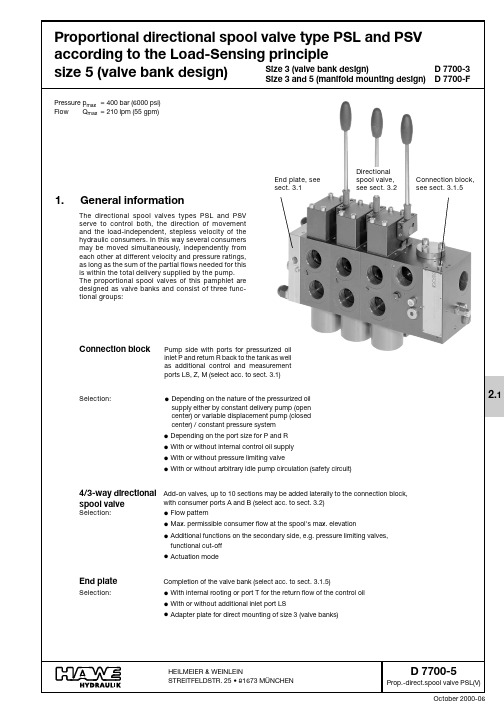
哈威HAWE阀样本D7700-2-cn
瓦茨工业公司检验阀技术数据表说明书
Check valves Technical Data Sheet2CS - SeriesPage 3WI - SeriesPage 3CO - SeriesPages 4 and 5FI - SeriesPages 6 and 7FO - SeriesPages 6 and 7FW - SeriesPages 6 and 7IN - SeriesPages 8 and 9IO - SeriesPages 10 and 11WM - SeriesPages 12 and 13IW - SeriesPage 14TO - SeriesPage 14AuxiliaryMountingToolsPage 15 Summary3Tfit!Other diameters on request.Mounting dimensionsProduct dimensionsO-ringflow (m /h)100908070605040302010d e l t a P (k P a )flow (m /h)100908070605040302010d e l t a P (k P a )4Ø CØ DØ EØ GAll dimensions are given in mm.The Watts check valves type CO with unique sealing principle offers outstanding performances.These check valves are used in plumbing fittings, sanitary taps and in threaded non-return valves where building codes and international standards are required.Other diameters on request.Approvals: K iwa (NL), Belgaqua (B), DVGW (D), NF - ACS (F),WRAS (UK), ETA - GDV (DK), SITAC (S), NSF (US).5100908070605040302010d e l t a P (k P a )Pressure loss-curveClassical guiding of valve stem Guiding of valve stem (WATTS)Some vibrations can occur at low flow rates (water flush atThanks to the unique guide system by slotted stem that eliminates the possibility of movement and optimal hydraulic profile, vibrations are eliminated.By providing this guidance without the possibility of move-ment avoids calcareous deposits and vibration, ensuring a flawless and quiet operation for years.6FI015 DN15FI - FO - FWThe Watts check valve type FI, FO and FW is a perfect slide-in cartridge with added advantages.The best performance in those inlet sides where tightening has to be simple. It is marked by its unique construction and its uni-versal applications.Approvals: K iwa (NL), Belgaqua (B),DVGW (D), NF - ACS (F), NSF (US).FI010 DN8FO015 DN15FO020 DN20FW010 DN10Approval: GDV (DK)7FI010 DN8FI015 DN150.40.81.21.62.02.42.83.23.64.04.85.66.47.28flow (m 3/h)100908070605040302010d e l t a P (k P a )Pressure loss-curveAll dimensions are given in mm.The Watts snap-in valve type IN is a compact and therefore easy to install check valve.The advantage for OEM applications is, that in case of a side- connection in the housing, the O-ring can be mounted first and secondly the check valve itself.This way the O-ring will not be damaged by the sharp edges of the side- connection.This check valve will meet all quality requirements.Its advantages are yours.Approvals: K iwa (NL), Belgaqua (B), DVGW (D), NF - ACS (F),WRAS (UK), ETA - GDV (DK), SITAC (S), NSF (US), AWQC (AUS).All dimensions are given in mm.92468101214161820flow (m 3/h)100908070605040302010Pressure loss-curve d e l t a P (k P a )IN025 - DN25IN032 - DN322468101214161820flo100908070605040302010Pressure loss-curved e l t a P (k P a )IN025 - DN25IN032 - DN320.81.62.43.24.04.85.66.47.28.0flow (m 3/h)100908070605040302010Pressure loss-curve d e l t a P (k P a )IN015 - DN15IN020 - DN200.81.62.43.24.04.85.66.47.28.0flo100908070605040302010Pressure loss-curved e l t a P (k P a )IN015 - DN15IN020 - DN208162432404856647280flow (m 3/h)100908070605040302010Pressure loss-curved e l t a P (k P a )IN040 - DN40IN050 - DN5008162432404856647280f100908070605040302010Pressure loss-curved e l t a P (k P a )IN040 - DN40IN050 - DN5010To meet the ever increasing quality requirements, Watts developed the snap-in check valve type IO.The O-ring is already mounted and fixated on the check valve, thus creating an easy to mount check valve.Approvals: K iwa (NL), Belgaqua (B), DVGW (D), NF - ACS (F),WRAS (UK), ETA - GDV (DK), SITAC (S), NSF (US).All dimensions are given in mm.110.81.62.43.24.04.85.66.47.28.0flow (m 3/h)100908070605040302010Pressure loss-curved e l t a P (k P a )IO015 - DN15IO020 - DN200.8 1.6 2.4 3.2 4.0 4.8 5.6 6.47.28.0flo100908070605040302010Pressure loss-curved e l t a P (k P a )IO015 - DN15IO020 - DN208162432404856647280flow (m 3/h)100908070605040302010Pressure loss-curve d e l t a P (k P a )IO040 - DN40IO050 - DN5008162432404856647280fl100908070605040302010Pressure loss-curved e l t a P (k P a )IO040 - DN40IO050 - DN5002468101214161820flow (m 3/h)100908070605040302010Pressure loss-curve d e l t a P (k P a )IO025 - DN25IO032 - DN322468101214161820flo100908070605040302010Pressure loss-curved e l t a P (k P a )IO025 - DN25IO032 - DN3212The Watts slide-in check valve type WM features a noiseless operation, very low pressure loss and absolute sealing at high and low back pressures.The split valve stem principle guarantees a trouble free operation for many years.Approvals: K iwa (NL), Belgaqua (B), DVGW (D),NF (F) except DN40, - ACS (F), ETA - GDV (DK),SITAC (S), NSF (US).Mounting dimensions Product dimensions13100908070605040302010Pressure loss-curved e l t a P (k P a )flow (m 3/h)100908070605040302010Pressure loss-curved e l t a P (k P a )flow (m 3/h)0.81.62.43.24.0 4.85.66.47.28.0flow (m/h)100908070605040302010Pressure loss-curved e l t a P (k P a )Pressure loss-curveflow (m 3/h)14Mounting dimensions Product dimensionsO-rings n o i s n em i d t c u d o r Pg n i r-Os n o i s n em i dg n i t n u oMOther diameters on request.15Auxiliary mounting toolsIn order to achieve a perfectly leaktight check valve construction, it is of crucial importance that mounting dimensions are respected.On each check valve data sheet, you will find the required mounting dimensions to be created in the housing to the check valve.In order to avoid any damage of the check valves and O-rings it is very important that check valves are mounted in the correct way.To support positioning and mounting in the right way Watts produced a mounting tool for every check valve.The dimensions of the tools are given below.Remark: dimensions are under usual reserve.All dimensions are given in mm.Via Brenno, 21 • 20853 Biassono (MB) • Italy Tel. +39 039 4986.1 • Fax +39 039 4986.222******************************•© 2017 WattsThe descriptions and photographs contained in this product specification sheet are supplied by way of information only and are not binding.Watts Industries reserves the right to carry out any technical and design improvements to its products without prior notice. Warranty: All sales and contracts for sale are expressly conditioned on the buyer’s assent to Watts terms and conditions found on its website at . Watts hereby objects to any term, different from or additional toWatts terms, contained in any buyer communication in any form, unless agreed to in a writing signed by an officer of Watts.CHECK-VALVES-TS-IT-W-UK-05-17-Rev0。
HAWE单向阀技术资料下载

HAWE单向阀技术资料下载哈威单向阀上海办事处,你只需提供正确的型号,我们都可以第一时间给您报价。
德国哈威单向阀又称止回阀或逆止阀。
用于液压系统中防止油流反向流动,或者用于气动系统中防止压缩空气逆向流动。
单向阀有直通式和直角式两种。
直通式单向阀用螺纹连接安装在管路上。
直角式单向阀有螺纹连接、板式连接和法兰连接三种形式。
液控单向阀也称闭锁阀或保压阀,它与单向阀相同,用以防止油液反向流动。
但在液压回路中需要油流反向流动时又可利用控制油压,打开单向阀,使油流在两个方向都可流动。
液控单向阀采用锥形阀芯,因此密封性能好。
在要求封闭油路时,可用此阀作为油路的单向锁紧而起保压作用。
液控单向阀控制油的泄漏方式有内泄式和外泄式二种。
在油流反向出口无背压的油路中可用内泄式;否则需用外泄式,以降低控制油压力。
HAWE单向阀安装位置HAWE单向阀就是止回阀旋启式止回阀安装位置不受限制,通常安装于水平管路,但也可以安装于垂直管路或倾斜管路上。
HAWE单向阀注意事项安装止回阀时,应特别注意介质流动方向,应使介质正常流动方向与阀体上指示的箭头方向相一致,否则就会截断介质的正常流动。
底阀应安装在水泵吸水管路的底端。
HAWE单向阀关闭时,会在管路中产生水锤压力,严重时会导致阀门、管路或设备的损坏,尤其对于大口管路或高压管路,故应引起止回阀选用者的高度注意。
HAWE单向阀只供防止各类管路或设备上流体介质逆流的单向启闭阀。
公称通径:21/16“~41/16“工作压力:2,000~15,000PSI温度:-60°C~+121°C(K,U)产品规范级别:PSL3~4产品性能级别:PR1~2材料级别:AA~FFHAWE单向阀技术资料下载HAWE单向阀常见故障①阀瓣打碎;②介质倒流。
引起阀瓣打碎的原因HAWE单向阀前后介质压力处于接近平衡而又互相“拉锯”的状态,阀瓣经常与阀座拍打,某些脆性材料(如铸铁、黄铜等)做成的阀瓣就被打碎。
哈威多路阀说明书

;=©1998 by HAWE HydraulikApril 2010-01D 7700-7F page 22.Type coding, overviewValve section (for individual orders, without sub-plate)Inlet section (for individual order, without sub-plate)SLF 7 - A 2 J 320/250 A 300/EA - G 24PSVF A B1 F / 400 - 7 - G 2416131211109875431167116151413121110987654322+Valve bankPSVF A S 1 F / 400/7 SAE-7- A2J 320/250/EA/6 SAE- A2H 320/320F1/EA/ 6 SAE - E4 - G 241Order examples:;Basic type coding for the valve bank or inlet section (see table 1 and 5 in sect. 3.1) as well as valve sections (see sect. 3.2)PSVF ASupply with pressurized oil by means of variable displacement pump (closed center)with a delivery flow controller, or as a second,separate unit if both valve banks are connec-ted to a constant pressure systemSLFIndividual valve section, without sub-plate<Additional elements (see table 2 and 4 in sect. 3.1)(no coding)Basic version S, W Additional damping device in gallery LS (onlywith PSVF , standard with PSLF)B, B 4 ... B 7Orifice in gallery LS (PSVF only)G Restrictor check valve (type PSLF)=Control oil supply (see table 7, sect. 3.1.3)(no coding)Without pressure reducing valve in case ofan external control oil supply (min. 20 bar up to max. 40 bar)1With integrated pressure reducing valve forthe internal supply of control oil (control pres-sure approx. 20 bar)2With integrated pressure reducing valve forthe internal supply of control oil (control pres-sure approx. 40 bar)>Optional 2/2-way solenoid valve for arbitrary idle pump circu-lation (see table 8, sect. 3.1.3)(no coding)Without directional valve, but prepared forretrofittingF , Z, ZM De-energized open = Idle pump circulationwhen valve is de-energizedD, V De-energized closed = Idle pump circulationwhen valve is energizedF ..or D..When a pressure is specified, with pressurelimiting valve which can be activated as a second pressure stage (e.g. F 80)PA, PB, PD Prop. pressure limiting valve, with variouspressure ranges ?Pressure limiting valve (main pressure limitation) in the inlet section (see table 9, sect. 3.1.3)(no coding)Without pressure limiting valve (type PSVFonly)/ ...Pressure limiting valve factory set to ... bar@Sub-plate for the inlet section (see table 3, sect. 3.1)/7Size 7, standard (tapped ports for P and RG 1 1/2 ISO 228/1 (BSPP))/7 SAE Size SAE (flange SAE 1 1/2” 6000 psi)A Size (see table 1 and 5, sect. 3.1)7Size 7BValve section - Basic function (see table 13, section 3.2.1)A 2 (standard) Spool valve with inflow controller for eachconsumerA 1Spool valve without inflow controller, suitablefor consumers, which are actuated individual-ly and successively but not simultaneously (no additional functions possible)A 5Inflow controller with enforced spring forhigher flowAX Blanking plate C Coding for the flow-pattern (see table 14, sect. 3.2.1 and 6 c)L, H, J, ODFlow coding for port A and B (see table 15, sect. 3.2.1).../...Coding for port A or B (independently selec-table)120, 160, 250, 320, 400ELS-pressure limitation (deviating from the mainpressure setting, lower pressure for the connected consu-mer) no shock valves (see table 16 and 18, section 3.2.1)(no coding)No LS-pressure limitation A..., B...Only for consumer port or B A...B...For consumer ports A and BD 7700-7F page 3F Functional cut-off (see table 17 and 18, sect. 3.2.1)(no coding)No functional cut-offF 1Electrical cut-off, consumer port AF 2Electrical cut-off, consumer port BF 3Electrical cut-off, consumer port A and BFP 1(2, 3)Like F1(2,3), however with electro-proportio-nal pressure limitationFPH 1(2, 3)Like FP1(2,3), however with additional push-button for manual emergency actuation S 1External hydraulic load signal pick-up fromthe control signal port U(consumer port A)and W (consumer port B)G Types of actuation (see table 19 and 20, sect. 3.2.1)/A Manual actuation/E Electro-hydraulic actuation/EA Electro-hydraulic and manual actuation/E0A Like /EA, however without actuation solenoid(prepared for retrofitting)/H Hydraulic actuation/H UNF Like /H, however with connection7/16-20UNF-2B SAE-4 (SAE J 514)/HA, /HEA Hydraulic, solenoid and manual actuation/HA UNF Like /HA,however with connection 7/16-20UNF-2B SAE-4 (SAE J 514)/C Detent(stepless)/ER, /EAR Electrical, 3-step detent/P Pneumatic actuation/PA Pneumatic actuation and manual actuation/... Suffix 1without hand leverWA, WA-EX Position sensorU Lift monitoring(side indication)H Sub-plate for the individual valve section (see table 21,section 3.2.2)/6 SAE Sub-plate size 7, ports A and B with flangeSAE 1 1/4” (6000 psi)/56 SAE Sub-plate size 7, prepared to accept valvesections size 5, ports A, B with flangeSAE 1 1/4” (6000 psi)/7Sub-plate size 7, ports A and B with G 1 1/2acc. to ISO 228/1 (BSPP)/56Sub-plate size 7, prepared to accept valvesections size 5, ports A, B with G 1 1/4 acc.to ISO 228/1 (BSPP)I End plates (see table 11, section 3.1.4)E 1With T-port for control oil returnexternally to the tank (basic type)E 4Like E 1, however with internal drain connec-tion, max. pressure 10 bar!J Solenoid voltage and version (see table 10, sect. 3.1.3)G 12..12 V DC, connection conf. EN 175 301-803 A,G 24..24 V DC, connection conf. EN 175 301-803 A,G 24 EX24 V DC, explosion-proof version, acc. toATEXG 24 EX 7024 V DC, explosion-proof version, acc. toATEX (ambient temperature 70°C)G 24 MSHA24 V DC, explosion-proof version, acc. toMSHAG 12 IS12 V DC, explosion-proof version, flame proof,intrinsically safe acc. to ATEX (I M2 Ex d ib I) AMP 12 K 412 V DC, connection via AMP Junior TimerAMP 24 K 424 V DC, connection via AMP Junior TimerS 12..12 V DC electr. connection via quarter turnplugS 24..24 V DC electr. connection via quarter turnplugD 7700-7F page 4D 7700-7F page 5D 7700-7F page 6D 7700-7F page 7D 7700-7F page 8D 7700-7F page 9D 7700-7F page 104.Characteristic data 4.1General and hydraulicType coding DesignMounting PSLF, PSVF und SLFDirectional spool valve for manifold mounting, up to 8 spool valves may be combined in a valve bank by means of sub-plates, all-steel designAnyP=Pressure inlet (pump)R=ReturnA ,B=Consumer portsU, W, X=Load-signal outlet at the indiv. spool valve sectionLS=Load-signal outlet e.g. connection of pump metering valve at PSVF.Attention: No pressure input!M=Pressure gauge connection (pump side)Z=Pilot pressure connection (20...40 bar inlet, 20 or 40 bar outlet)T=Control oil return portY=Load-signal inlet port (end plate E 2 and E 5)Installation position PortsSize 5Indiv. section 4 x M10Valve bank M10Size 7Inlet section PSLF, PSVF12.0Valve section Actuation A, E, F, H, P24.6 1)EA, PA25.0 1)FA, HA24.61)FEA, HEA25.01)Sub-plates/7, /56/6 SAE, /56 SAE12.0End plates E 1, E 4 3.0See dimensionaldrawings in sect. 5 ++1)+ 0.4 kgat version withfunctional cut-off(coding F.., FP.., FPH..acc. to table 16)P, R, A, B=Acc. to dimensional drawings (see sect. 5.1.10)M, LS, Z, T, Y=G 1/4 conform. ISO 228/1 (BSPP) (see sect. 5.1.10)U, W, X=Acc. to dimensional drawings (see sect. 5.1.10)Indiv. valve section and sub-plates: All surfaces corrosion-inhibiting, gas nitrided(Solenoid at actuation E... and additional functions F1...F 3, FP 1...FP 3, FPH 1...FPH 3 inc galva-nized and olive-green anodized)Port sizeSurface coatingMass (weight) approx. (kg)Temperature Ambient: approx. -40 ... +80°C; Fluid: -25 ... +80°C, pay attention to the viscosity range!Start temperature down to -40°C are allowable (Pay attention to the viscosity range during start!),as long as the operation temperature during consequent running is at least 20K (Kelvin) higher.Biodegradable pressure fluids: Pay attention to manufacturer's information. With regard to the com-patibility with sealing materials do not exceed +70°C.Observe restrictions for versions with ex-proof solenoid!Rec. contamination class Operating pressure ISO 4406 18/14p max= 400 bar; Ports P, P1, A, B, LS, M, YThe max. pressure achievable at the consumer side of the spool valves is lowered by the amount equivalent to the internal control pressure drop at the 3-way flow regulator of the PSLF (see curves) or at the pump flow regulator (PSVF).Return port R(R1) ≤20 bar; port T pressure less with separate pipe (e.g. 8x1) to the tank. It is recommended to employ end plate E 1, E 2, E 3, etc. with an additional leakage port, in case hig-her return pressure is anticipated. Port Z approx. 20 or 40 bar (acc. to coding, see table 7) (outlet);≤40 bar (inlet)Control circuit Flow For control pressure, see Q-I-characteristics. The internal control oil circuit is sufficiently protect-ed against malfunctions caused by contamination by means of a disk filter.Acc. to the specifications in table 14, in sect. 3.2.1Pressure fluid Hydraulic fluid (DIN 51524 table 1 to 3); ISO VG 10 to 68 (DIN 51519)Viscosity range: min. 4; max. 1500 mm2/sec; Optimal operation range: 10...500 mm2/secAlso suitable are biodegradable pressure fluids of the type HEPG (Polyalkylenglycol) and HEES(synth. Ester) at operation temperatures up to +70°C. HETG (e.g. rape seed oil) or water basedfluids e.g. HFA or HFC must not be used!D 7700-7F page 31D 7700-7F page 326.3.5Seal kitsSize 7Inlet section (control section)DS 7700-F 71Valve section DS 7700-F 72Sub-plateDS 7700-F 74Control grooveTapped plug6.3.4Notes on changing the spoolThe valve spools are not mated to one spool housing. Therefore valve spools can be changed at any time to adapt to changing consumer consumption.The following routine is to be followed particularly:Advice on changing the valve spool1.Slacken screws ;(ISO 4762-M5x8-8.8-A2K), remove spring cover2.Remove screw <(M 6x40, machined flat head screw dra-wing No. 7709 042)3.Remove spring assembly including spring cap =4.Slacken screws >(ISO 4762-M5x50-8.8-A2K)5.Lift lever housing including spool out of spool housing,drawing ?@6.Remove circlip DIN 6799 3,2 and remove bolt A B7.Assemble with (new) spool in reverse sequence Attention:The control grooves of the valve spool should always be installed towards the end plate! Exception: Valve spools with flow coding 400 do not show control grooves.Indications for angling the lever housing by 180°(inversion of the shifting mode)As set out in 1. - 7. above, however instead of a new valve spool the existing one has to be disconnected, angled at 180° and remounted (see above mentioned note). The in-termediate plate C together with the lever housing, have to be angled at 180°.All lever housings of the valve bank have to be rotated!Lever housing angled at 180°6.3Notes regarding assembly, installation and conversion。
阀门产品样本国标安全阀

阀门产品样本罗浮阀门集团有限公司目录1、A21型PN16~40外螺纹连接弹簧封闭微启式安全阀 (1)2、A21型PN64~100外螺纹连接弹簧封闭微启式安全阀 (2)3、A21型PN160~320外螺纹连接弹簧封闭微启式安全阀 (3)4、A27H-10、A27H-16型外螺纹连接弹簧带扳手微启式安全阀 (4)5、A28H型PN16外螺纹连接弹簧带扳手全启式安全阀 (5)6、A37H、A43H型PN16~40双联弹簧带扳手微启式安全阀 (6)7、A38Y型PN16~40双联弹簧带扳手全启式安全阀 (8)8、A40Y型PN16~64带散热片弹簧封闭全启式安全阀 (10)9、A41H、A41Y型PN16~100弹簧封闭微启式安全阀 (12)10、A41Y型PN160~320弹簧封闭微启式安全阀 (15)11、A42F 、A42Y、KA42Y(抗硫)型PN16~100弹簧封闭全启式安全阀 (17)12、42Y型PN160~320弹簧封闭全启式安全阀 (21)13、WA42Y型PN16~40波纹管弹簧全启式安全阀 (22)14、A44Y型PN16~100弹簧封闭带扳手全启式安全阀 (22)15、A44Y型PN160~320弹簧封闭带扳手全启式安全阀 (26)16、A47H型PN16~40弹簧带扳手微启式安全阀 (27)17、A48Y型PN16~100弹簧带扳手全启式安全阀 (29)18、A48SH型PN16~40弹簧带扳手全启式安全阀 (32)19、A48SH型PN64~160高温高压弹簧带扳手全启式安全阀 (34)20、A42Y-P5545V、A62Y-P55 140V型气控碟形弹簧安全阀 (36)21、A68Y型对焊连接弹簧全启式安全阀 (37)22、A49H-40型主安全阀及配套GA49H-40型冲量安全阀 (38)23、A49Y-100、A49Y-100V型主安全阀及其配套冲量安全阀 (40)24、A69Y-P54140V型DN100主安全阀及其配套冲量安全阀 (42)25、A69Y-100、A69Y-100V型DN150主安全阀及其配套冲量安全阀 (43)26、GA41H型PN16~40杠杆式安全阀 (44)27、GA42H型PN16~100单杠杆式安全阀 (45)28、GA44H型PN16~64双杠杆式安全阀 (47)29、A411F-25、A412F-25、NA42F-25型内装式安全阀 (48)30、JA22H-2.5、JA22W-2.5P型外螺纹连接静重式安全阀 (50)31、FA72W型PN10真空负压安全阀 (51)32、AH42F型平衡式安全回流阀 (52)33、A61型弹簧微启式安全阀 (53)34、AY42H PN400型、LA802Y-600型安全溢流阀 (55)35、石化专用安全阀 (57)36、AQ-20型空压机安全阀 (58)37、LFA46F型先导式安全阀系列 (59)1、A21型PN16~40外螺纹连接弹簧封闭微启式安全阀使用范围:本产品可用于石油、化工行业。
哈威HAWE阀样本D7770-cn
阶段就被抑制住,并使其迅速消失。详细的功能介绍和选择阻尼的说明(特别是对极限条件)请参阅资料 B7770
回转
举升
折弯
伸缩
PSV 型比例多路换向阀(规格 3) 参阅样本 D7700-3 V30D 型变量轴向柱塞泵 参阅样本 D7960
D7770
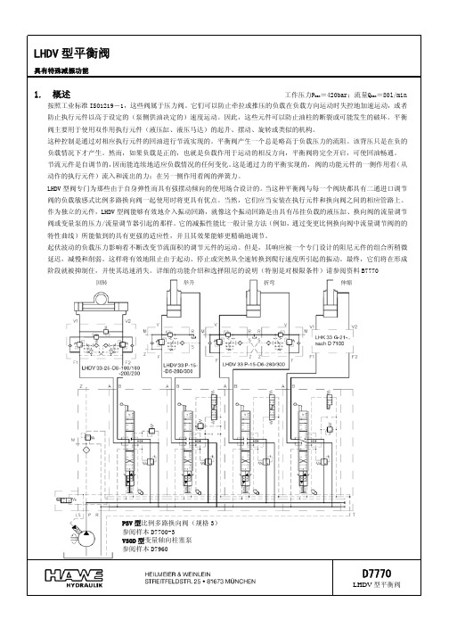
LHDV 型平衡阀
D7770 第 2 页
2,可提供的结构形式,主要数据
1)相应的连接块 No.7770 024=0.4kg
流通方向
工作方向(平衡功能)V→F、V1→F1 或 V2→F2
自由流通 F→V、F1→V1、F2→V2
开启比
阀关闭时约 1:8.2(几何比)
阀开启时约 1:1.2 至 1:6.4 根据阻尼孔的直径而定见第 2 节的表 3
压力调节
无论在调节或变更设定压力时,都必须使用压力表!下表中所给出的接口 F(F1 和 F2)中有孔圆盘每转
动作的执行元件)流入和流出的力;在另一侧作用着阀的弹簧力。
LHDV 型阀专门为那些由于自身弹性而具有强摆动倾向的使用场合设计的。当这种平衡阀与每一个阀块都具有二通进口调节
阀的负载敏感式比例多路换向阀一起使用时将更具有优点。当然,它们应当安装在执行元件和换向阀之间的相应管路上。
作为独立的元件,LHDV 型阀能够有效地介入振动回路,就像这个振动回路是由具有吊挂负载的液压缸、换向阀的流量调节
安装在 V 口周围的任何角度上。在安装面上需一定心凸台,见第 4 节的外形尺寸图。
D7770 第 3 页
用于交替负载方向的双向平衡阀 通过内部控制油路分别使回油侧 V1→F1 或 V2→F2 开启不需要外控管路。订货示例:
平衡阀的设定压力(bar) 执行元件 V1 侧 执行元件 V2 侧
液压阀样本
液压阀样本----500f39f6-7161-11ec-b616-7cb59b590d7d 最大流量最大使用压力阀孔加工图代码ep08-2a-01-z-04ep08-2a-01-z-05ep10-2a-01-z-05ep12-2a-01-z-05ep16-2a-01-z-05ep19-2a-01-z-05ep17-2a-01-z-05ep21-2a-01-z-05ep20-2a-01-z-05ep13-2a-01-z-05l/min30407015015040701504040l/min20350巴350巴350巴350巴350巴350巴页码12345678910页码11sv-08sv-08sv-10sv-12sv-16o19-eo17-eo21-esv-20t13a阀孔加工图代码最大流量最大使用压力ep08-2a-01-z-052通常闭型附带弹簧最大流量和最大工作压力阀孔加工图代号ep08-2a-01-z-85ep10-2a-01-z-85ep12-2a-01-z-85ep16-2a-01-z-85ep17-2a-01-z-85ep21-2a-01-z-85l/min407015015070150酒吧350350350页码121314151617sv-08sv-10sv-12sv-16o17-eo21-eep08-x-y-z-04扭矩3-4牛米例如:ep08-2a-01-n-04例如:ep08-2a-01-m-04COELEC-04w6662hex.22.2torque25-35nm3/4"-16unf-2a228最大额定压力:最大额定流量:塞孔代码:35030sv-0825-350.13巴尔/明姆克安装扭矩:重量:工作温度:内部泄漏:-40~120℃0.15cc/min(3滴/分)在最大压力350bar时25um或者更好90%额定电压滤波精度:最低电压要求:103040压力-p(巴)121086420线圈必须单独订购。
哈威多路阀E7700-3-GB
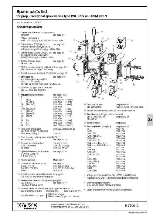
September 2002-02E 7700-3 page 2E 7700-3 page 3E 7700-3 page 4E 7700-3 page 5Connection blocksNote: There is a minimum order value requirement, when ordering spares !Please specify the complete order coding and part No. when ordering spare parts. Subject to change without notice !Order coding NomenclaturePart No.Item111Connection block 7778 06811Connection block 7778 060/111Connection block 7778 070111Connection block 7778 56611111111Bolt ( standard )7778 015a 2or or or Bolt for coding H 7778 015b 21111111Spring ( standard )7650 0113or or or Spring for coding H7778 03431111111Controller piston (complete)7778 04041111111Screw7620 041/151111111Type plate dep. on type ( exact spec. is required )64444444Grooved drive stud ISO 8746-2,3x4-A272222222Seal ring DIN 7603-A4x8x1-Cu82222222Hexagon head screw ISO 4017-M4x6-A2-709or or or or or or or Directional seated valve type WN1 F for coding F acc. to D 7470 A/110or or or or or or orDirectional seated valve type WN1 D for coding D acc. to D 7470 A/1101111Screw 6380 013111Screw 6380 0131211Screw6380 01312a1111Carburetor jet M4/0.612a111Filter screw7807 02412b111111Skt.-head screw ISO 4762-M8x10-A2-70131111111Valve taper 7700 057/1141111111Spring 7700 0511********Screw7700 058161111111Hexagon nut ISO 4035-B M8x1-A2-70171111111Cap nut7700 054181111111Sleeve, (complete)7625 110191111111Screw, (complete)7625 17220or or or or or or or Pressure reducing valve (complete) type AM1-20 for coding 1acc. to D 745821or or or or or or orPressure reducing valve (complete) type AM1D-40 for coding 2acc. to D 74582111111Gap type filter at port M for coding 1or 27778 048/12211Gap type filter at port M for coding 1or 27778 5482213334Tapped plug (DIN 908)-G1/4 A NBR, complet with elastic seal6013 25062334Tapped plug SAE 090 109B-4 SAE HOLLOW HEX PLUG including 6013 251323O-ring AC0-568-9041111111Pre-load and dampening valve (complete) for PSV coding S 7778 30124standard with PSL and PSMor or or or or or Dampening valve (complete) for coding G 7778 30324or or orScrew for coding B 7778 06225or orScrew7778 08026orTapped plug7778 036261Piston for coding U ; UH 7778 014271Spring for coding U ; UH7120 502281Tapped plug for coding U ; UH 7480 033291111111Seal kit DS 7700-31see page 3330-40P S V U N F 44../...-3P S L U N F 4../...-3P S M 5../...-3P S V 55../...-3P S V 45../...-3P S L 5U (U H )../...-3P S L 5../...-3E 7700-3 Seite 6E 7700-3 page 7E 7700-3 page 8E 7700-3 page 9E 7700-3 page 10Order coding NomenclaturePart No .Item 1111Lever housing (complete)dep. on type1incl. shaft and linkage ( not indiv. available )4444Skt.-head screw ISO 4762-M5x50-A2-7022222Back-up ring 7709 00932222Back-up ring 7709 01742222Washer7709 00751111Circlip DIN 6799-96or or or or Circlip DIN 6799-9-1.4122 ( stainless ) for coding S 61111Cap ( stainless )7709 01871111Strainer ( stainless )7709 01981111Lever bracket7709 00892222Grub screw ( stainless ) ISO 4026-M6x6-A2-70102222Grub screw ( stainless ) ISO 4026-M6x16-A2-70111111Pin ISO 8748-5x20-St1211Lever (complete) ( standard )7709 02013or or Lever (complete)for coding 27709 070131111Bolt7709 004142222Circlip DIN 6799-3.2151111Spacer7709 0031611Spring cap (complete)7709 0241711Spring7709 0311811Spring cap (complete)7709 0251911Detent (complete)7709 039201111Washer7709 029211111Flat head screw DIN 7991-M6x35-8.8221111Spring dome7709 021/1231111Retainer for coding G7709 04823a4444Skt.-head screw ISO 4762-M5x8- A2-7024or or or or Skt.-head screw ISO 4762-M5x16-12.9-zinc plated for coding G 24a1111Seal kit DS 7700-32see page 3343, 44, and 50C 1..C S 1..C ..;C S ..A 1..;A S 1..A ..;A S ..Manual actuation type A, AS, A1, and AS1C, CS, C1, and CS1Note: There is a minimum order value requirement, when ordering spares !Please specify the complete order coding and part No. when ordering spare parts. Subject to change without notice !Electro-hydraulic actuation Type E, EA., EC, and EAC.Order coding NomenclaturePart No.Item 11Lever housing (complete) dep. on type 1For spare parts, see page 18-1911Housing7709 013211Bearing needle DIN 5402-2.5x23.8 2.12Grub screw ISO 4026-M6x20-45 H 32Hexagon nut ISO 4035-M6-A2-7042Cap nut7450 022544Skt.-head screw ISO 4762-M5x40-A2-7061Hexagon head screw ISO 4017-M6x6-A2-70711Spacer7709 003822Blanking screw including ( applies only to E0A and E0AC ):7709 0479O-ring 12.42x1.78 HNBR 90Sh and O-ring 9x1.5 NBR 90Sh and Seal ring 7625 109/12222Prop. pressure reducing valve insert type PM1-11 including 7625 150e10O-ring 8x1.5 NBR 90Sh and (55)Seal ring 7625 109/1(56)1111Twin solenoid ( 12V DC )7709 050-G1211or Twin solenoid ( 24V DC )7709 050-G2411or Ex-proof version ( 24V DC,EEX m 120 T4 )7709 050 ex-G24113333Skt.-head screw ISO 4762-M5x50-A2-70121111Plug MSD3-3091311O-ring 10.82x1.78 HNBR 90Sh 1411Detent (complete)7709 1741511Washer7709 1731611Circlip DIN 472-32x1.51711Spring cap with 7709 02618Sleeve 7709 02811Spring cap 7709 0241811Spring 7709 0301911Spring 7709 0311911Spring7709 0312011Spring cap with 7709 02721Sleeve 7709 02811Spring cap 7709 025211111Washer7709 0292211Flat head screw DIN 7991-M6x35-8.82311Flat head screw DIN 7991-M6x75-8.8231Spring dome 7709 022/1241Spring dome 7709 021/12411Housing7709 1712411Flange for coding G7709 04824a 44Skt.-head screw ISO 4762-M5x8-A2-702544Skt.-head screw ISO 4762-M5x10-A2-702544Skt.-head screw ISO 4762-M5x16-12.9 zinc plated for coding G 25a 11Tapped plug including elastic seal 7758 220261111Seal kit DS 7700-32see page 3337a-51E E A E C E A CNote: There is a minimum order value requirement, when ordering spares !Please specify the complete order coding and part No. when ordering spare parts. Subject to change without notice !P HP APOrder coding NomenclaturePart No.Item 1Housing 7709 082111Housing7709 09211Lever housing (complete)dep. on type 2For spare parts, see page 18-191Housing7709 0742Indiv. available components:2Circlip DIN 6799-3,2 2.11Bolt7709 0042.21Seal ring DIN 7603-A4x8x1-Cu31Hexagon head screw ISO 4017-M4x6-A2-7041Screw7700 60651O-ring 28.3x1.78 NBR 90Sh 61Piston 7709 075712Cap nut7450 022812Hexagon nut ISO 4035-M6-A2-70912Grub screw ISO 4026-M6x20-45 H104Skt.-head screw ISO 4762-M5x80-A2-701144Tension rod DIN 940-M5x125-8.8-A2K 1144Cap nut DIN 1587-M5-A2K121Hexagon nut ISO 4035-M6-A2-701311Sleeve (complete)7709 09614with O-ring 7.65x1.78 NBR 70Sh (65)1Piston 7709 0841511Piston7709 0941511Roll pin ISO 8748-2x14-St 1611Rod guide (complete)7709 08317with O-ring 7.65x1.78 NBR 70Sh (65)with O-ring 26.64x2.62 NBR 90Sh (66)1Rod guide (complete)7709 09317with O-ring 7.65x1.78 NBR 70Sh (65)with O-ring 26.64x2.62 NBR 90Sh (66)1Rod 7709 085181Rod 7709 095181Rod 7709 07618111Bolt7709 00419222Circlip DIN 6799-3.2201Spacer including bearing needle DIN 5402-2x9,87709 081211Spacer7709 087211Spacer including bearing DIN 5402-2x9,87709 0872111O-ring (69)211Spacer7709 003222Blanking screw (complete) with type E0 with 7709 04723O-ring 9x1.5 NBR 90Sh withO-ring 12.42x1.78 HNBR 90Sh and Seal ring 7625 109/1111Spring cap including 7709 02624Sleeve 7709 028111Spring 7709 03025111Spring7709 03126111Spring cap including 7709 02727Sleeve 7709 028111Washer7709 02928111Flat head screw DIN 7991-M6x35-8.82911Spring dome 7709 022/1301Spring dome7709 021/130111Flange for coding G7709 04830a 444Skt.-head screw ISO 4762-M5x8-A2-7031or Skt.-head screw ISO 4762-M5x16-12.9 zinc plated for coding G 31a 111Seal kit DS 7700-32see page 3337a-43111Seal kit DS 7700-33see page 3364-69Pneumatic actuation Type P , PA, and PHNote: There is a minimum order value requirement, when ordering spares !Please specify the complete order coding and part No. when ordering spare parts. Subject to change without notice !E 7700-3 page 31End platesOrder coding NomenclaturePart No.Item 1End plate (complete)7778 121/1a 1or End plate UNF (complete)7778 521a 11End plate (complete)7778 121/1c 11End plate (complete)7778 121/1e 11End plate (complete)7778 121/1b 1or End plate UNF (complete)7778 531b 11End plate (complete)7778 121/1d 11End plate (complete)7778 121/1f 11End plate (complete)7778 129a 1or End plate UNF (complete)7778 529a 11End plate (complete)7778 129b 1or End plate UNF (complete)7778 529b 11End plate (complete)7778 129c 1or End plate UNF (complete)7778 529c 11End plate, complete 7778 129d 1orEnd plate UNF (complete)7778 529d 11Intermediate plate (complete)7778 0791Indiv. available components:1111End plate 7778 0811a 11End plate 7778 033/11a 1111End plate 7778 0431a 11End plate UNF 7778 5311a 1111End plate UNF 7778 5431a 11Grub screw ISO 4026-M4x4-22H 211Grub screw ISO 4026-M5x5-45H211111Check valve insert type RC1 (complete)acc. to D 6969 R 3111Check valve insert type RB0(complete)with UNF acc. to D 6969 R 31211121Tapped plug including 6013 25064elastic seal DIN 908-G 1/4 A1211Tapped plug (complete)SAE 0901B-4 with4O-ring HOLLOW HEX PLUG and O-ring AC0-568-90411111Ball DIN 5401-7 G10511111Threaded disc 7271 2346111Threaded disc with UNF 7778 53461111Seal ring DIN 7603-Cu-A5x7.5x171111Skt.-head Screw ISO 4762-M5x6-A2-7081111Filter cap, not available with UNF ports 6406 02191111Fine filter, not available with UNF ports 6406 016101111Filter, not available with UNF ports 7245 0211111Directional seated valve type WN1H-G..acc. to D 7470 A/1123333333333Tension rod type E1-E6and E17-E20 see page 3313a-16b 33O-ring see seal kit DS 7700-31page 333522Ring see seal kit DS 7700-31page 3335a 1Seal kit DS 7700-21see page 3370-72E 20 ( U NF )E 19 ( U NF )E 18 ( U NF )E 17 ( U NF )E 6E 5E 4 ( U NF )E 3E 2E 1 ( U NF )Z P L 32Note: There is a minimum order value requirement, when ordering spares !Please specify the complete order coding and part No. when ordering spare parts. Subject to change without notice !E 7700-3 page 32Order coding NomenclaturePart No.Item 11Spring dome 7186 051/111Screw 7184 037d 2or Screw7184 037a1Hexagon nut ISO 4032-M8-A2-703x xSpacer:40.5 mm thick 5585 023b 1 mm thick 5585 023e 1.5 mm thick5585 023c 2 mm thick5585 023f 11Seal ring 7186 053511Nippel 7186 040611Spring ...80 bar 7000 646/17or or Spring ...160 bar 7000 647/17or or Spring ...315 bar 7000 649/17or or Spring ...500 bar 2564 005a 711Washer 7186 052811Spring guide 7186 054911Dampening piston (complete)7186 07510Indiv. available components:11Spring 7186 05510.111Spring 7000 67310.211Sleeve 7000 67210.31Screw 7184 009111Winged nut 7000 436121Turn knob 7000 411/1131Pin ISO 8748-3x161411Seal kit DS 7700-31see page 3342a+bM V J 6...RM V J 6...Corresponding tothe respectivepressure setting Order coding Nomenclature Part No.Item1Directional seated valve type WN1F or WN1Dacc. to D 7470 A/11with 4x Skt.-head screw ISO 4762-M4x70-12.9 zinc plated 1 a for version with second pressure stage:with 4x Skt.-head screw ISO 4762-M4x85-12.9 zinc plated 1 a 1Intermediate plate (complete)7470 06323Ring 6540 049(35a)1Grooved drive stud ISO 8741-2.5x831Cap nut 7700 05441Hexagon nut ISO 4035-B-M8x1-A2-7051Screw 7700 05861Spring 7700 05171Valve taper 7700 057/181Seal kit DS 7700-31see page 3335 and 37Directional seated valve type WN1F(D)Order example:PSL 3 F /350-3-G.. (as idle circulation valve Emergency Stop)PSL 3 F80/350-3-G.. (with second pressure stage)1a Max.torque 4 Nm1437537678235a35335a 35Pressure limiting valve type MVJ 6Order example:PSL 3/400-3PSV 3/320-3Max.torque 100 Nm2341542a 67891010.110.210.342b141312411Items 2-9 and 35-37intermediateplate (complete)acc. to Sk 7470 104Note: There is a minimum order value requirement, when ordering spares !Please specify the complete order coding and part No. when ordering spare parts. Subject to change without notice !E 7700-3 page 33 Tension rod:Seal kit :DS7700-31(Connection block)Nomenclature Part No.Item1Seal ring DIN 7603-Cu-A6x10x1221Seal ring DIN7603-Cu-A5x9x1242O-ring 14x1.78 HNBR 90 Sh302O-ring 17.12x2.62 HNBR 90 Sh311O-ring 17.17x1.78 HNBR 90 Sh321O-ring 13.94x2.62 HNBR90 Sh32a5O-ring 4.47x1.78 HNBR 90 Sh331Seal ring DIN 7603-Cu-A10x14x1,5343O-ring 6x1.5 NBR90 Sh353Ring6540 04935a1Ermeto ED22x1.5364Seal ring DIN 7603-Cu-A8x12x2371Seal ring7625 109/1381O-ring 9x1.5 NBR90 Sh391Fitting seal DRV 100116-NB 650401O-ring 23.52x1.78 HNBR 90 Sh42a1O-ring 15x2 HNBR90 Sh42bSeal kit:DS7700-33(additionally for version with pneumatic actuation) Nomenclature Part No.Item 1O-ring 25.07x2.62 NBR70 Sh64 4O-ring 7.65x1.78 NBR70 Sh65 1O-ring 26.64,x2.62 NBR90 Sh66 1O-ring 25.07x2.62 NBR90 Sh67 1O-ring 7.65x1.78 NBR90 Sh68 1O-ring 4.47x1.78 HNBR90 Sh69Seal kit:DS7700-22(for intermediate plate type ZPL32)Nomenclature Part No.Item 1O-ring 12.42x1.78 HNBR90 Sh70 3O-ring 10.82x1.78 HNBR90 Sh71 4O-ring 2.90x1.78 HNBR90 Sh72 Seal kit:DS7700-32(Spool valve section)Nomenclature Part No.Item 2Seal ring DIN 7603-Cu-A16.7x22x211 2O-ring 14x1.78 HNBR 90 Sh30 1O-ring 17.12x2.62 HNBR 90 Sh31 1O-ring 17.17x1.78 HNBR 90 Sh32 1O-ring 13.94x2.62 HNBR90 Sh32a 4O-ring 4.47x1.78 HNBR 90 Sh33 2Seal ring DIN 7603-Cu-A10x14x1.534 2Seal ring DIN 7603-Cu-A8x12x237 4Seal ring DIN7603-Cu-A6x10x137a 1O-ring 13x1.5 HNBR 90 Sh41 1O-ring 34.65x1.78 HNBR 90 Sh43 2O-ring 12.42x1.78 HNBR 70 Sh44 2O-ring 36.17x2.62 HNBR 90 Sh50 2O-ring 12.42x1.78 HNBR90 Sh51 2O-ring 3x1.5 NBR90 Sh52 2O-ring 6.86x1.78 HNBR90 Sh53 1O-ring 6.07x1.78 HNBR 90 Sh54 2O-ring 8x1.5 NBR 90 Sh55 2Seal ring7625 109/156 2O-ring 23.47x2.62 NBR 90Sh57Seal kits:Number of added-on valve sectionsEnd plate2 Tension rod M10x... Part No. 7778 910type Item1234567891011121314152 Skt.-head screwISO 4762-M10x80-A2-70145195245293343393442490540590640690740790E1-E613a ISO 4762-M10x100-A2-70165215263313363412460510560610660710758807E17-E2013a ISO 4762-M10x70-A2-70135185235285332380435480533ZPL3213a 1 Skt.-head screw 1 Tension rod M8x... Part No. 7778 908ISO 4762-M8x80-A2-70140190240288337387436486535585635685733783E1-E613b ISO 4762-M8x100-A2-701602102603083574074565ß6555605655705753803E17-E2013b ISO 4762-M8x70-A2-70135185232280330380430480530ZPL3213b2 Washer ISO 7089-10,5-300 HV-A214a1 Washer ISO 7089-8,4-300 HV-A214b-- 2 Hexagon nuts ISO 4032-M10-A2-70-A2K15a -- 1 Hexagon nut ISO 4032-M8-A2-70-A2K15b -- 2 KORREX protective cap M10 NR.610 black16a -- 1 KORREX protective cap M8 NR.608/13 black16bNote: There is a minimum order value requirement, when ordering spares !Please specify the complete order coding and part No. when ordering spare parts. Subject to change without notice !。
哈威多路比例阀样本
U
Automatic reduction of the pump idle circulation pressure by means of a by-pass valve (only type PSL), see also
note in sect. 7.1 a
H
Raised circulation pressure of the 3-way flow controller (approx. 14 bar, type PSL)
? Optional 2/2-way solenoid valve for arbitrary idle pump circulation (see table 9, sect. 3.1.4)
(no coding)
Without directional valve, but prepared for retrofitting
functional cut-off
• Actuation mode
End plate
Selection:
Completion of the valve bank (select acc. to sect. 3.1.5)
• With internal rooting or port T for the return flow of the control oil • With or without additional inlet port LS • Adapter plate for direct mounting of size 3 (valve banks)
@ Tool adjustable, piloted pressure limiting valve (main pressure limitation) in the connection block (see sect. 3.1.4, table 10)
哈威主动式液压站操作与维护手册

Hi-Flow 控制阀值球阀阀门, 适用于蒸汽和水流控制, 1 2 到2-1 2 大小, 2路或3路
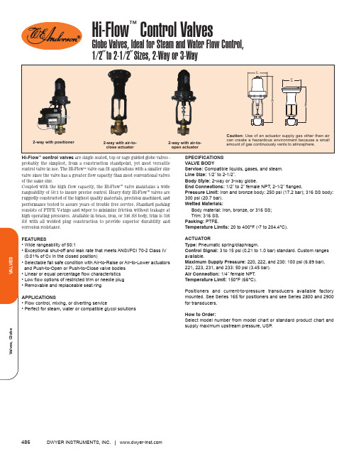
Hi-Flow ™control valves SPECIFICATIONS VALVE BOdy2-way with air-to-open actuator2-way with positionerValves, GlobeVALVES487Hi-Flow ™Control Valves2-Way Simplified Selection Guide with Standard ProductsPipe Size 1/2˝3/4˝1˝1-1/4˝1-1/2˝2˝*2-1/2˝Cv 100%6.4510.7517.4225.3032.1050.3078.60Body MaterialBRONZE316SSBRONZE316SSBRONZE316SSBRONZE 316SSBRONZE 316SSBRONZE 316SSIRONBRONZE 316SSMax USP psi (bar)3-15 (.21-1.0)250(17.2)300(20.7)250(17.2)250(17.2)285(19.7)300(20.7)166(11.4)250(17.2)166(11.4)300(20.7)98(6.8)245(16.9)250(17.2)98(6.8)245(17.0)300(20.7)65(4.5)168(11.6)250(17.2)65(4.5)168(11.6)300(20.7)31(2.1)88(6.1)175(12.1)31(2.1)88(6.1)175(12.1)105(7.2)105(7.2)105(7.2)Ain (mm)19-3/4(501.7)19-3/4(501.7)19-3/4(501.7)20-3/8(517.5)19-3/4(501.7)20-3/8(517.5)20-3/16(512.8)20-13/16(528.6)20-3/16(512.8)20-13/16(528.6)20-5/16(515.9)20-15/16(531.8)25-13/32(645.3)20-5/16(515.9)20-15/16(531.8)25-13/32(645.3)20-11/16(525.5)21-5/16(541.3)25-25/32(654.8)20-11/16(525.5)21-5/16(541.3)25-25/32(654.8)20-15/16(531.8)21-9/16(547.7)26-1/32(661.2)20-15/16(531.8)21-9/16(547.7)26-1/32(661.2)26-1/4(666.8)26-1/4(666.8)26-1/4(666.8)Cin (mm)7-3/4(196.9)7-3/4(196.9)7-3/4(196.9)10-5/8(269.9)7-3/4(196.9)10-5/8(269.9)7-3/4(196.9)10-5/8(269.9)7-3/4(196.9)10-5/8(269.9)7-3/4(196.9)10-5/8(269.9)13-3/8(339.7)7-3/4(196.9)10-5/8(269.9)13-3/8(339.7)7-3/4(196.9)10-5/8(269.9)13-3/8(339.7)7-3/4(196.9)10-5/8(269.9)13-3/8(339.7)7-3/4(196.9)10-5/8(269.9)13-3/8(339.7)7-3/4 (196.9)10-5/8(269.9)13-3/8(339.7)13-3/8(339.7)13-3/8(339.7)13-3/8(339.7)Max. USP psi (bar)3-15 (.21-1.0)250(17.2)300(20.7)250(17.2)250(17.2)300(20.7)300(20.7)192(13.2)250(17.2)192(13.2)300(20.7)115(7.9)250(17.2)250(17.2)115(7.9)300(20.7)300(20.7)80(5.5)235(16.2)250(17.2)80(5.5)235(16.2)300(20.7)44(3.0)140(9.7)250(17.2)44(3.0)140(9.7)272(18.8)190(13.1)190(13.1)190(13.1)Bin (mm)18-7/16(468.3)18-7/16(468.3)18-7/16(468.3)19-1/8(485.8)18-7/16(468.3)19-1/8(485.8)18-7/8(479.4)19-9/16(496.9)18-7/8(479.4)19-9/16(496.9)19(482.6)19-11/16(500.1)23-1/8(587.4)19(482.6)19-11/16(500.1)23-1/8(587.4)19-3/8(492.1)20-1/16(509.6)23-1/2(596.9)19-3/8(492.1)201/16(509.6)23-1/2(596.9)19-5/8(498.5)20-5/16(515.9)23-3/4 (603.3)19-5/8(498.5)20-5/16(515.9)23-3/4 (606.3)24-7/16(620.7)24-7/16(620.7)24-7/16(620.7)Cin (mm)7-3/4(196.9)7-3/4(196.9)7-3/4(196.9)10-5/8(269.9)7-3/4(196.9)10-5/8(269.9)7-3/4(196.9)10-5/8(269.9)7-3/4(196.9)10-5/8(269.9)7-3/4(196.9)10-5/8(269.9)13-3/8(339.7)7-3/4(196.9)10-5/8(269.9)13-3/8(339.7)7-3/4(196.9)10-5/8(269.9)13-3/8(339.7)7-3/4(196.9)10-5/8(269.9)13-3/8(339.7)7-3/4(196.9)10-5/8(269.9)13-3/8(339.7)7-3/4 (196.9)10-5/8(269.9)13-3/8(339.7)13-3/8(339.7)13-3/8(339.7)13-3/8(339.7)Use the chart below to aid in the selection of Hi-Flow™ Control Valve. As long as the maximum upstream pressure (USP) is less than, or equal to, the value listed, the model shown can be manufactured and calibrated to your specific requirements. Specify maximum upstream pressure, USP, when ordering.Control Valves - Hi-Flow™ Series, 2-Way, Stocked ModelsPipe Size 1/2˝3/4˝1˝1˝1-1/4˝1-1/4˝1-1/2˝2˝2˝Cv100%6.4510.7517.4217.4225.3025.3032.1050.3050.30Body Material Bronze Bronze Bronze Bronze Bronze Bronze Bronze Bronze Bronze Set at USP psig (bar)125 (8.6)125 (8.6)125 (8.6)125 (8.6)98 (6.8)125 (8.6)125 (8.6)88 (6.1)125 (8.6)Adjustable USPRange psig (bar)96-200 (6.8-13.8)81-155 (5.6-10.7)123-166 (8.5-11.5)71-155 (4.9-10.7)66-98 (4.6-6.8)121-165 (8.3-11.4)104-137 (7.2-9.5)68-88 (4.7-6.1)116-145 (8.0-10.0)* Valve has flanged connections. Max. USP (PSI) is for Linear Valves. Consult factory for optional trim.For filters and regulators see pages 562 through 566.CALL TO ORDER | 800/872-9141b Items are subject to Schedule B discounts.Model 2000VA32-230-QS 2001VA32-230-QS 2002VA32-230-QS 2002VA32-231-QS 2003VA32-230-QS 2003VA32-231-QS 2004VA32-231-QS 2005VA32-231-QS 2005VA32-233-QS Price$1118.00b 1159.00b 1251.00b 1374.00b 1340.00b 1463.00b 1621.00b 1756.00b 2191.00b Model(Air-To-Open)2000VA32-2302000VA42-2302001VA32-2302001VA32-2312001VA42-2302001VA42-2312002VA32-2302002VA32-2312002VA42-2302002VA42-2312003VA32-2302003VA32-2312003VA32-2332003VA42-2302003VA42-2312003VA42-2332004VA32-2302004VA32-2312004VA32-2332004VA42-2302004VA42-2312004VA42-2332005VA32-2302005VA32-2312005VA32-2332005VA42-2302005VA42-2312005VA42-2332006VA12-2332006VA32-2332006VA42-233Model(Air-To-Close)2000VA32-2202000VA42-2202001VA32-2202001VA32-2212001VA42-2202001VA42-2212002VA32-2202002VA32-2212002VA42-2202002VA42-2212003VA32-2202003VA32-2212003VA32-2232003VA42-2202003VA42-2212003VA42-2232004VA32-2202004VA32-2212004VA32-2232004VA42-2202004VA42-2212004VA42-2232005VA32-2202005VA32-2212005VA32-2232005VA42-2202005VA42-2212005VA42-2232006VA12-2232006VA32-2232006VA42-223Price$1118.00b 1674.00b 1159.00b 1282.00b 1862.00b 1985.00b 1251.00b 1374.00b 1976.00b 2099.00b 1340.00b 1463.00b 1898.00b 2254.00b 2377.00b 2812.00b 1498.00b 1621.00b 2056.00b 2480.00b 2603.00b 3038.00b 1633.00b 1756.00b 2191.00b 2776.00b 2899.00b 3334.00b 2363.00b 2629.00b 4298.00bPrice$1118.00b 1674.00b 1159.00b 1282.00b 1862.00b 1985.00b 1251.00b 1374.00b 1976.00b 2099.00b 1340.00b 1463.00b 1898.00b 2254.00b 2377.00b 2812.00b 1498.00b 1621.00b 2056.00b 2480.00b 2603.00b 3038.00b 1633.00b 1756.00b 2191.00b 2776.00b 2899.00b 3334.00b 2363.00b 2629.00b 4298.00bUse the standard models chart to aid in the selection of the most economical Hi-Flow Way Control Valve for your application. Specify maximum upstream pressures (USP’s);; Diverting: USPC; based on standard 3-15 psi (.21-1.0 bar) pneumaticFor diverting service, add USP U and USP C to determine the shutoff pressure. For mixing service compute: (USP U- USP C) + (USP L- USP C) to determine the shutoff pressure.Dimension DataControl Valves, 3-Way Simplified Selection Guide with StandardUSP(S)PSI (bar)250(17.2)300(20.7)250(17.2)300(20.7)200(13.8)250(17.2)200(13.8)300(20.7)120(8.4)250(17.2)120(8.3)300(20.7)80(5.6)200(13.8)250(17.2)80(5.5)200Model3000WA32-2203000WA42-2203001WA32-2203001WA42-2203002WA32-2203002WA32-2213002WA42-2203002WA42-2213003WA32-2203003WA32-2213003WA42-2203003WA42-2213004WA32-2203004WA32-2213004WA32-2233004WA42-2203004WA42-221Price$1674.00b2366.00b1835.00b2633.00b1989.00b2112.00b2768.00b2891.00b2216.00b2339.00b3197.00b3320.00b2413.00b2536.00b2971.00b3603.00b3726.00bDWYER INSTRUMENTS, INC. 488。
哈电超临界阀门选型手册

当介质最高温度>450℃时,标注工作温度和工作压力,工作压力需用 P 标
识并在 P 字的右下角附加介质最高温度数字。该数字是以 10 除介质最高温度数
值所得的整数。如:工作温度为 540℃,工作压力为 10MPa 的阀门,其代号为
PW5410V,
8. 阀体材料代号用汉语拼音字母表示:
(表 6)
代 号
1
3
4
5
6
7
9
蝶 阀 结 构 形 式
C 代 号
(表 4-3)
杠 杆 式 垂直板式 斜 板 式 减压阀结构形式 薄膜式 弹簧薄膜式 活塞式
0
1
3
代 号 1
2
3
(表 4-4)
波纹管式 杠杆式
4
5
(表 4- 5)
C (圈)
50
转速 24
( r/min)
电机功率 0.37
( kw)
扬州电力设备修造厂电动装置详表
DZW30 DZW30(I)
DZW45
DZW60
DZW90 DZW90(I)
DZW120 DZW120(I)
DZW180 DZW500
300
450 600
900
1200
1800
5000
50
120 120
7
封
闭
全 启 式
8
带控制机构 全 启 式
6
先 导 式
9
全 启 式
2
杠
单 杠 杆
角形微启式
5
杆
双 杠 杆
全 启 式
4
套 筒 式
阀门阀体长度及重量表
91 95 99 113 132 181 206 257 317 412 750 1042 1274 1420 1522
第1页 共10页
编制日期:2007年10月30日
公称直径 电动楔式钢制单闸板闸阀 L=
Z941H-40 美标法兰连接钢制闸阀 L=
Z41H-150Lb 美标法兰连接钢制闸阀 L=
130 150 160 180 200 230 290 340 350 400 480 600 650 750 850
3.3 5 6.3 19 24 29 48 60 95 100
5.5 6 9.1 11 19 24 29 44 65 99 145
8 9.1 11.8 12 15.8 17 23 32 44.4 65.5 99.3 147
H41X-10.16 静音止回阀 L= HC42X(T)-10.16.25Q 橡胶瓣止回阀 L= HC44X(SFCV)-10.16.25 国标旋启式止回阀 L=
H44H-16 H44H-25 H44H-40
编制:谢正幸
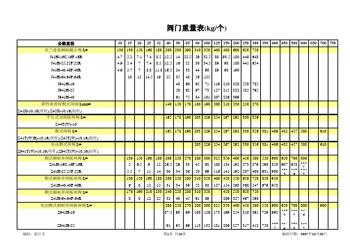
阀门重量表(kg/个)
10 15 20 25 32 40 50 65 80 100 125 150 200 250 300 350 400 450 500 600 650 700 750
292 334 356 432 508 559 660 787 838 889 991 1092 1194 1397
44 55 80 145
309 522 779 1108 1503 1939 2733 3214 4177
48 48 51 51 57 57 70 70 76 76 89 89 114 114
85 150 240 350
267 292 318 356
哈威 (HAWE)NBVP 16 型截止式换向阀

外控口 G 1/4
气动 P
滚针 滚柱
手动 A
主要参数,也参见 3.2 节
UN = 12V DC UN = 24V DC UN = 110V AC,50/60Hz(98V DC) UN = 230V AC,50/60Hz(205V DC)7) UN = 12V DC UN = 24V DC UN = 110V AC,50/60Hz(98V DC) UN = 230V AC,50/60Hz(205V DC)7) UN = 24V DC,8W
(20...250)
DG36
(4...12)
DG365
(12...170)
DG364
(4...50)
DG5E-250
DG5E-400
DG5E-600 `压力表 D7077
100
160
250
400
600
表 6:T 油口附加元件
R,S,Z,Y1)
ZD,G,D,DS,W, Q,RS,SR,K,J
接口 A
G,D,DS,Q,RS,S R,W,K
NBVP 16 S/B 0,8
/2
- WG 110
NBVP 16 G/B 0,8 R/ABR2,0 BBR1,5 /A3 B9/400/S - GM 24 - 3/8
① ②
A和B油口附加元件 (见表4)
P油口附加元件 (见表3)
管连接阀板
操纵形式 (见表7) T油口附加元件 (见表6) 压力继电器和/或 压力表(见表5)
运行时的相对通电时间(100%ED 标于 电磁铁上) 环 境 温
度
θU (℃)
断开能量
WA≤ 0.4 Ws
表面覆层 (电磁铁) DIN 50981 – 铁/锌 12 bk cC
哈威比例多路换向阀维修

规格 设计形式
规格3,5 (板接式) D7700-F
规格5 (组合式) D7700-5
规格2 (组合式) D7700-2
规格3 (组合式) D7700-3
December 2007-00
三规格多路阀三通流量阀结构二规格多路阀三通流量阀结构
* PSL阀为负载反馈原理一旦LS信号受阻也会造成系统无法建压,
梭阀卡死;LS信号油路受阻,检查LS通路,曾经出现过在自行拆装阀件时未按工作章程操作将油路的O型密封圈堵住了负载反馈信号。
在自行组装
* 如果使用的三规格尾板为E2或E5型检查
是否未堵死或完全未堵。
二次限压阀
SL3-E5尾板
4.1.2某执行元件无压力或压力较低
现象:如果就某一片换向阀无法建压,而其他阀阻可以正常使用:
* 检查二次限压是否设定于正常的压力值,是否在二次拆装时压力已有变动。
* 检查二次限压内部阀芯是否有污物卡死,检查二次限压阀的阀芯及其基座是否有磨损。
换向阀芯
手柄座限位结构
如果是二个或多个执行机构同时工作,泵的流量小于多个执行元件需求流量的总和,压力高的
二通流量补偿阀
弹簧定位腔
整套阀电控无流量输出
所有阀片的电液控制都没有动作,而手动操作可
检查装在接口M中的精过滤器,拆下并清洗。
连接
块中大过滤器被脏物堵住了 * 拆下先导减压阀
检查所有的运动零件是否有污物,动作是否平常,
尾板单向阀
电控减压阀位置
PSL3规格产品。
手柄座结构
阀的设定压力应高于泵的设定压力20%左右,以确保变量泵的及时工
3
4
6.4 板式规格:
备忘: 20。
hawe液控单向阀技术参数
hawe液控单向阀技术参数1.概述液控单向阀是一种常用于液压系统中的控制元件,它能够实现液压系统在特定条件下的单向流动。
本文将介绍h aw e液控单向阀的技术参数,包括工作压力、流量、尺寸等方面的详细信息。
2.工作压力h a we液控单向阀的工作压力是指其能够承受的最大压力范围。
根据实际需求,ha we液控单向阀的工作压力可调整,并具有以下参数:-最大工作压力(Pma x):xx xM Pa-最小工作压力(Pmi n):xx xM Pa3.流量流量是指液控单向阀在单位时间内通过的液体数量。
h aw e液控单向阀的流量参数可以根据需求选择不同的型号,并具有以下参数:-最大流量(Qm ax):x xx L/mi n-最小流量(Qm in):x xx L/mi n4.尺寸h a we液控单向阀的尺寸参数包括阀体长度、直径等信息,这些参数对于系统设计和安装非常重要。
以下是h awe液控单向阀的尺寸参数:-阀体长度(L):xx x mm-阀体直径(D):xx x mm-进口和出口管道尺寸:xx xm m5.温度范围h a we液控单向阀能够在一定的温度范围内正常工作,超出该温度范围可能会导致阀门性能下降甚至故障。
以下是ha we液控单向阀的温度参数:-最低工作温度(Tmi n):xx x℃-最高工作温度(Tma x):xx x℃6.性能特点h a we液控单向阀具有以下主要的性能特点:-高精度控制:采用先进的液控技术,能够实现精确的流量控制和压力控制。
-快速响应:具有快速的开启和关闭时间,能够迅速响应液压系统的需求。
-耐腐蚀性:采用高质量的材料和特殊的表面处理技术,具有良好的耐腐蚀性能。
-可靠性高:经过严格的性能测试和质量控制,具有卓越的可靠性和耐久性。
7.应用领域h a we液控单向阀广泛应用于各种液压系统中,包括工业设备、航空航天、农业机械等领域。
它们可用于控制液压系统的单向流动,确保系统的安全和稳定运行。
- 1、下载文档前请自行甄别文档内容的完整性,平台不提供额外的编辑、内容补充、找答案等附加服务。
- 2、"仅部分预览"的文档,不可在线预览部分如存在完整性等问题,可反馈申请退款(可完整预览的文档不适用该条件!)。
- 3、如文档侵犯您的权益,请联系客服反馈,我们会尽快为您处理(人工客服工作时间:9:00-18:30)。
换向滑阀
联接板尾板
液压符号:(见3.1.4节)
减压阀
9 14 22 34
见代码1
具有进口调节阀的换向阀可以选装的次级限压阀(无缓冲阀)
F 型 FP2型
无进口调节阀 作为预选开关的三FP3型
FP2型
FP1型
可能的组合:
带进口调节阀的 A2..(A5..)
PSL 5.../...3型连接块中的限压阀(先导式) PSL3/(4).../...3型连接块中的限压阀(直动式) 测量时的油粘度约为60mm/s
流量Q(lpm) PSL..型连接块 循环压力P→R
换向阀
P→A(B),A(B) →R
次级限压阀
按3.2.1节表16的代码A...B...;C...
流量Q(lpm)
流量Q(lpm)
流量Q(lpm)
背压(b a r )
设定压力(b a r )
二通进口调节阀
比例压力限制阀,
参见第3.1.4节表9,型号PA…PD 参见第3.2.1节表17,型号FP(H)1(2,3)
负载压力P a 和B (b a r )
执行元件流量的控制曲线
(装有进口调节阀的SL3—X2../..型换向阀的实例) 控制电流I(A) 24VDC 12VDC
液压控制H.F.的控制压力(bar)
手动A.C 操纵杆的角度.
表15的流量代码
表15的流量代码
控制电流I(A)
流量Q(lpm)
0470/EN
通过霍尔传感器监控阀芯的行程
电流-阀芯曲线
信号电压
测量时油的粘度约为60mm
阀芯开
启
量
线圈b 线圈a.
5.1 连接快
减压阀
限压阀
尾板未注尺寸参见5.2节
中间板ZPL32和ZPL52(同时可见D7700-3和D7700-5)
减压阀
限压阀
截止换向阀
尾板未注尺寸参见5.2节
油口标准参见DIN ISO 228/1(BSPP)
油口标准参见SAE J 514:
换向阀见5.3++节
见表8中型号2
1) 该尺50mm,2) PSL..H..油口按照
5.2 尾板
扭距
23Nm
扭距9.5Nm 油口按照:
换向位置b换向位置a
限制B位流量的挡块1)限制A流量的挡块1)
限制行程
的中间板
终端块侧
连接块侧
1)行程调节螺钉为M5
辅助块参见 5.8
节
EA、EOA 型操纵方式
手动应急操纵
按钮代码TH
限制A 位流量的挡块
插头可转180°
EOA-型操纵方式的螺堵 (Z 7709 047配套件还有 O 形圈12.42x1.78 HNBR 90Sh
O 形圈9x1.5 NBR 90 Sh 和O 形圈7625 109/1)
B 端限制位流量的堵块
ET、EAT、ETH 和EATH 型操纵方式
E 型操纵形式
A…型 B…型 A…B…型
连接块侧终端块侧
A..
B..S1..型
接口U和W=G1/8(BSPP)
标注的数据(换向阀和操
纵方式)见5.3至5.5节!
A..
B..FP1(2,3)
A..
B..FPH1(2,3)型
FPH…型的按
钮(手动应急操纵)
/2 AS.. BS.. /2 AN.. BN.. /2 DRH /UNF 2 AS.. BS.. /UNF 2 AN.. BN.. /UNF 2 DRH 型
型
1)内六角螺钉ISO4762-
M6x35―A2―70最大拧紧力矩9.5Nm
/ZSS ,/ZVV 型
螺纹接口A 和B(所有结构形式):
内六角螺钉 ISO4762-M6xg-A2-70最大扭矩9.5Nm 组装的换向阀块按照5.3节
/2 /UNF2型
下图示出液压起重机的典型阀组。
PSL41/250-3 32L40/40C200/A 32L25/63A100F1/EA 32H63/25F3/A 31M25/40/A 板
结构形式/3AL 没有
/3XV 和/UNF3XV 型没有
EM32V 型截止式
换向阀
内六角螺钉ISO4762-M6x50
-A2-70最大扭矩9.5Nm
螺纹接口A 和B
/3… =G1/2(DIN ISO 228/1(BSPP))
/UNF3…=7/8-14UN-2B(SAE-10,SAEJ514)
辅助块按照表19 ZPL3S(V)/E 型
ZPL3D(S) ZPL3D(S)/…型EMZ1D(S)型
电磁阀
按照D7490/1
芯行程(=节流状况)必须重新设置,以使通往执行元件的流量保持恒定。
该执行元件的流量能够近似地用公式计算: √0.2·△P控制(Q A、B=执行元件的流量,Q
量,使它的流量与其它执行元件或系统的压力无关。
控制油槽
终端板
侧
连接块侧
PSV 3S./...-2 or PSV UNF 2S./..-2型
接口 DIN ISO 228/1(BSPP)
Y=G1/4
28。