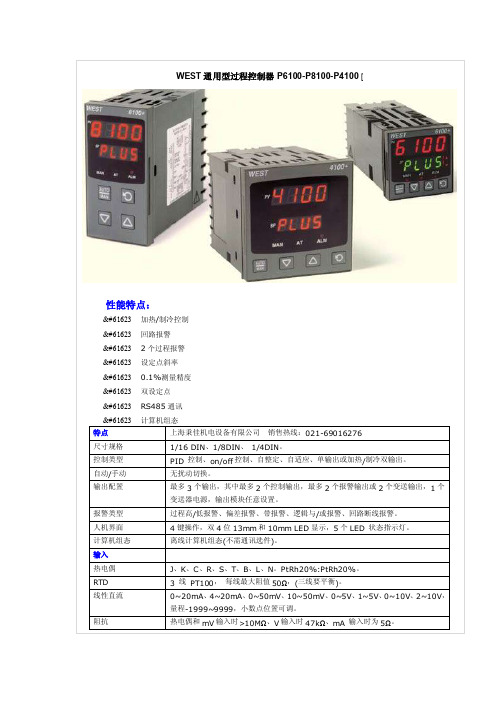
WestP6100116DIN通用型过程控制器
[WEST]P4100_P6100_P8100说明书
![[WEST]P4100_P6100_P8100说明书](https://img.taocdn.com/s3/m/14b499d308a1284ac8504372.png)
7.4 产品信息显示模式 .....................................................25
4.24 输出 2 – SSR 驱动.....................................................18
4.25 输出 2 – 固态继电器 ...................................................18
4.26 输出 2 – 线性直流 .....................................................19
注意: 在仪表接线端子处有此警告标志,在仪表接线时请仔细阅读本手册 本手册使用产品型号: P4100, P6100 & P8100
ii
Danaher Sensors & Controls
1/4 -DIN, 1/8 -DIN & 1/16 -DIN 控制器、显示仪和程序控制器手册
目录
目录...................................................................................................................................... iii 如何使用本手册 ..................................................................................................................... 1 1 简介..............................................................................................................................2 2 安装..............................................................................................................................3
Sartorius XQ 6100 6100 B电子搅拌计量秤使用及操作指南说明书

SartoriusXQ 6100, XQ 6100 B.Electronic Paint Mixing ScalesInstallation and Operating InstructionsSartoriusXQ 6100, XQ 6100 B.Please read these installation and operating instructions care-fully before operating your new scale.With this Sartorius Scale you have acquired a sophisticated,user-friendly electronic precision weighing instrument whichwill enable you to consistently match any colour to meet yourpaint supplier's high quality Standards.When operating this scale, please observe a few simple basicrules.Should you have additional questions after familiarizing yourpaint with this manual, please contact your paint supplier.2Contents.PageEquipment Supplied 5Installation Instructions 6Startup 7 Operation 8 Examples for Paint Mixing 9Calibration 15 Accessories (Options) 17Spezifications 1734 1 Weighing pan 2 Power receptacle3 Weight and linear range display4 TINTER/ADDITIVE key5 Set 100% key6 Access switch (for calibration)7 Tare control 8 PRINT key (functions only if the scalehas a built-in interface)9 RECALL WEIGHT-Taste 10ON/OFF key11 %/g key 12Manufacturer’s label (on the bottom of thebase plate of the scale)5Equipment Supplied. Do not miss out on the benefits of our warranty. Please fill out the warranty card, indicating the date of installa-tion, and return the card to your Sartorius dealer. Carefully unpack the scale and the accessory components. Save all packing material for future use. The equipment supplied comprises the components shown on the left: - Scale - Dust cover - AG adapter - Weighing pan lf you wish to send in your scale for repair work, please pro-ceed as follows: - remove all splashes or spills of paint - include a description of the equipment failures/faults. This will save you time and unnecessary expense for servic-ing. Please replace the cardboard between the scale base and the weighing pan (1) to prevent damage to the weighing system during shipment.6 Installation Instructions.Your Sartorius Scale provides exact readouts even under less than ideal conditions.However, exposure to extreme heat, vibrations or drafts may adversely affect the weighing accuracy and should be avoided whenever possible.The scale can be adapted to your particular requirements and to the specific ambient conditions simply by changing the menu code settings in the scale operating program. Please contact your dealer for assistance.After you have plugged your scale into the AC adapter and turned it on, allow for at least 30 minutes warmup. Once the scale has been warmed up, the STANDBY feature will enable you to skip the warmup procedure.Important NoteMake sure to unplug the AC adapter from the wall outlet be-fore you connect or disconnect additional devices (printer or PC) to or from the interface connector (Option). Startup.Remove the white backing from the adhesive disks on the dust cover. Attach the dust cover to the scale base by slightly pressing down on the adhesive disks.Mount the weighing pan (1) on the scale.Double-check to be sure that the base dust cover does not come in contact with the weighing pan.Your scale is powered by an AC adapter. Check that the volt-age rating printed on this unit is identical to your local line voltage.Plug the line cord of the adapter into the power receptacle of the scale. Now plug the AC adapter into an electrical or wall outlet.Whenever possible, avoid connecting your scale to over-loaded networks (compressors or similar equipment).lf you have problems with your local line power supply, use a suitable voltage stabilizer or an emergency power supply unit (Option). Be sure to contact your dealer for technical informa-tion.7Operation.Press the ON/OFF key (10) to turn the scale on or off. The display will go out whenever you turn off the scale. All other circuits will remain energized (STAND-BY state). This means the scale is immediately ready to operate without re-quiring warmup the next time you switch it on. Important Note To use the STANDBY feature, the scale must have been plugged into the AC adapter for at least 30 minutes (initial warmup). After the scale is turned on, an automatic self-test of the scale's electronic circuitry is performed. This self-test ends with the readout 0.0 g. Any other readout indicates an error. In this case, please con-tact your dealer, describing exactly what the display reads8 lf you wish to use a Container or if the weight display does not indicate 0.00 g (or the equivalent with the weight unit of your choice), press the tare control to zero the display.Important NoteThe small circle in the lower left-hand corner shows that the scale has been exactly tared so the display reads "0."Do not wait to replace worn dust covers.Make sure that paint spills over the sides of the housing do not harden, making the pan stick to the base. Frequent cleaning with solvents (such as paint thinner) will warp the dust cover which may then push against the pan, causing the readout to drift.9Examples for Paint Mixing. 1st Example Mix paint components with hardener (35% of the total weight of the paint quantity) and 20% thinner. The 20% thinner is in proportion to the total weight of the paint components and hardener. ——————————————————————————— Place an empty container on the scale and tare ——————————————————————————— Weigh in the 1st paint component according to your formula and then store it - press the key (4) ——————————————————————————— weigh in the 2nd paint component according to your formula and then store it - press the key (4)———————————————————————————10 You can obtain a display of the total net weight of the paint components by pressing thekey (9)——————————————————————————— To store the total net weight as 100 % –press the key (5)The decimal place will automatically disappear once the total weight is stored as 100 % or "E" will be displayed if the paint components are too light for the particular shade of paint. If "E" is displayed, press the RECALL WEIGHT key and in-crease the minimum amount of the individual paint components. ——————————————————————————— Add 35% hardener——————————————————————————— To display the momentary weight(paint components + hardener) –press the key (11)——————————————————————————— To store the total weight-press the key (9)———————————————————————————11Again, to store the total weight as 100 % – press the key (5) ——————————————————————————— Add 20% thinner Important Note: Make sure that the 20% thinner is in proportion to the total weight of the paint components and to the hardener. ——————————————————————————— to display the update total weight (paint components + hardener + thinner) – press the key (11) ——————————————————————————— The key (9) deletes the stored factor for calculation the percentages..12 2nd ExampleMix paint components with 13.5% hardener and 6.5% thinner. These percentages are in proportion to the total weight of the paint quantity(1st paint component + 2nd component = 100%).——————————————————————————— ^Place empty container on the scale and tare.——————————————————————————— To weigh in the paint components according to your for-mula and store them, see "1st Example" on page 9. ——————————————————————————— Display the total net weight of the paint components by press-ing thekey (9)———————————————————————————13To store the total net weight as 100 % - press the key (5) The decimal place will automatically disappear once the total weight is stored as 100 % or "E" will be displayed if the paint components are too light for the particular shade of paint. lf "E" is displayed, press the RECALL WEIGHT key and in-crease the minimum amount of the individual paint components.. ——————————————————————————— To store the amount as 100% – press the - key (4) ——————————————————————————— Add 13.5% hardener ———————————————————————————14 To add and store the updated total weight,press the key (4)——————————————————————————— Add 6,5% thinner——————————————————————————— Display the total net weight in percent by pressing thekey (9)——————————————————————————— To display the total net weight in the particular weight unit se-lected (in this case “g”) –press the key (11) ——————————————————————————— The key (9) deletes the stored factor for calculating the percentages.15Calibration.Have your scale checked and recalibrated, if necessary, by your dealer on the basis of a regular maintenance schedule. lf you have an accurate calibration weight (5,000 g ± 0.03 g; see Sartorius "Accessories" on page 17), proceed as follows: Remove the protective cap located on the front right of your scale and slide the access switch (6) in the direction of the ar-row. Turn off the scale, hold down the TINTER/ADDITIVE key (4) and briefly press the ON/OFF key (10). Upon the completion of the self-test release TINTER/ADDITIVE key when "C" is displayed. Unload the scale and tare. Press the TINTER/ADDITIVE key (4) when the display reads zero. "CAL" and the calibration weight readout will now be displayed.Centre the calibration weight on the weighing pan. Array Now the weight unit symbol is displayed. lt indicates the endof the calibration procedure.Relock the calibration access function by sliding the accessswitch back to its original setting, and replace the protectivecap.After calibration, use the ON/OFF key (10) to turn the scale offand then on again.Even if you do not calibrate your scale, this will not affect theaccuracy of the mixing ratio so you will always obtain the cor-rect shade of paint, provided you weigh in the componentscorrectly.However, the overall amount of your paint formula may slightlyvary.16Accessories (Options).Dust cover 69 60Q610Calibration weight (1 x 5000 g) 7072 13Antitheft locking device 6087For information on additional accessories, please contact yourdealer.Options:InterfaceExternal rechargeable batteryPrinterVoltage stabilizerEmergency power supply unitSpecifications.Model XQ 6100 XQ 6100 BCapacity g61006100 Readability g0,10,1 Tare range (by subtraction) g 6100 6100Standard deviation g ≤± 0,05 ≤± 0,5Max. linearity g ≤± 0,1 ≤± 0,5Stabilization (typical) s 1,5Display update— at stability (depends on the filter level selected— when load is changed ss0,1; 0,2; 0,40,1Adaptation to operating requirementand ambient conditions by selecting one of 3 optimised filter levelStability range d 0,25 ... 32 (selectable)Ambient temperature range K 273 — 313 (0o C .. +40o C)Allowable relative humidity % 15 ... 85 (moisture-proof rating; non-condensing) Sensitivity driftwithin 10 ... 30o C /o C ≤± 5 ∙ 10-6≤± 2,5 ∙ 10-5Pan size mm 235 x 180Scale base (W x D x H) mm 250 x 270 x 65Net weight, approx. kg 4 3,5Line voltage,(mains); frequency: 50-60 Hz115 or 230 V, depending on the AC adapter used Allowable voltage fluctuation -20% (15)Power consumption VA 7,5 (typical)Wattage rating of the scale for an inputvoltage of 12 Vw 0,55 0,3617Sartorius AGB37070 GöttingenP Weender Landstraße 94–108, 37075 GöttingenT (0551) 308-0,F(0551) 308-3289Internet: Copyright by Sartorius AG, Göttingen, Deutschland.All rights reserved. No part of this publication may beprinted or translated in any form or by any means withoutthe prior written permission of Sartorius AG.Sartorius AG reserves the right to make change to the technology, features, specification and design of the equipment without notice.。
west p4100
选件插槽 2
零件号
继电器输出 ...............................PO2-C10
线性输出 mA/V DC...................PO2-C21
SSR 输出 ..................................PO2-C50
可控硅驱动输出 ........................PO2-C80
选件插槽 3
零件号
继电器输出 ...............................PO2-C10
线性输出 mA/V DC...................PO2-C21
SSR 输出 ..................................PO2-C50
24VDC 变送输出 .................... PO2-W08
0 至 55°C(贮存温度-20 至 80°C),相对湿度 20% 至 95%,无冷凝。 100 至 240V AC 50/60Hz 7.5VA(可选 20 至 48V AC 7.5VA / 22 至 65V DC 5W)。 IEC IP66(背部防护等级为 IP20)。 CE,UL 和 ULc
JCX-161控制系统产品说明书

FeaturesFeaturesThe Bridge Navigational Watch Alarm System (BNWAS) main purpose is to monitor the presence of watch officers and their alertness for early detection of unsafe sailing conditions. Calling functionsAlso available on the unit is the emergency call function which triggers all devices (buzzers) to activate. In addition, officer call also available which provides audible notice for backup officer at 2nd stage alarm.Dual LED backlightThe JCX-161 incorporates many display modesreadily available on a highly visible 4.5-inch LCDdisplay. Besides the display being fully dimmableand having backlit keys, it features dual LEDbacklight (white and orange), making it easy tooperate in various light settings on the bridge. AccessoriesOperationMotion sensorAn optional infrared motion sensor removes the need for the officer to manually press a button to stop the alarm. The sensor detects movement of the officer, which, once detected, will not allow the alarm to trigger.Uniform operationIn keeping with the company’s philosophy of an easy to use Man Machine Interface, the new generationdisplays have allowed JRC’s engineers to develop an exciting new software approach for uniform operation.Contrast Menu Cursor/Enter4.5-inch LCDDeactivate alarm Emergency call Buzzer Clear/BackDisplayDimmeralarms but also when the BNWAS is connected to other navigation equipment such as radar (JMA-9100) or ECDIS (JAN-901B), the alarm is reset when the officer physically operating the controls.The user can define aninterval sequence ofbetween 3 and 12 minutes.This will only give a visualindication. The alarm can bereset at any point in time.There is a visual indicator ofthe time countdown. Afterthe preset interval, an alarmsequence will go into effect. Manage other alarmsWhen any connected equipment alarm is activated, the BNWAS displays a list of alarm informationIn the box• Display + Bracket• Control unit• Buzzer (2x)• Reset button (3x)• Operation cardNWZ-4650 Weight 600 g (+ bracket 130 g)142 mm 175 mm 127 mm162 mm142 mm127 mmCutout dimensionsControl unitNCK-175 Weight 4,5 kg291 mm 105 mm 280 mmBuzzerNVS-785 Weight 200 gReset buttonNCJ-895 Weight 200 gLED warning lamp (option)NCD-2257 Weight 200 g70 mm 47 mm 100 mm 70 mm 47 mm100 mmMotion sensor (option)NYG-5 Weight 400 gReset button waterproof (option)NCJ-896 Weight 500 g70 mm 70 mm 47 mm60 mm100 mm 100 mm70 mm 100 mm47 mmJCX-161IMO compliant ✓Control unit NCK-175Power supply: 100-120V/200-240V AC ±10%, 50/60Hz, Power consumption: 2.5W Back up power: 24V DC -10%/+30%Display unit NWZ-46504.5-inch monochrome LCD (128 by 64 dots)Backlight: white and orange LED selectable Dimmer levels: bright, medium, darkSerial in/output: 1x port RS-422, 1x port RS-485Power supply: 12V DC (powered from control unit), Power consumption: 4W Buzzer NVS-785Tone: continuous on/off (default on)Sound pressure: high 85dB(A) and low 75db(A) (default low)Power supply: 12V DC (powered from control unit), Power consumption: 0.4W Reset button NCJ-895Color: yellowMechanical life: 1 million pressesPower supply: 12V DC (powered from control unit), Power consumption: 0.6W LED warning lamp NCD-2257Color: redDimmer levels: bright, medium, darkPower supply: 12V DC (powered from control unit), Power consumption: 0.5W Motion sensor NYG-5Type: infrared sensorDetection range (temperature 20°C):Horizontal 100°, vertical 81°, distance up to 5 mPower supply: 12V DC (powered from control unit), Power consumption: 0.4W Reset button WP NCJ-896Color: yellowMechanical life: 1 million pressesPower supply: 12V DC (powered from control unit), Power consumption: 0.6W Interfacing6x input reset button2x input reset by external navigational equipment (radar and/or ecdis)2x input reset by motion sensor (5x inputs for reset button may also be used)1x input automatic mode (autopilot)1x input emergency call (shared with reset button input)1x output system fail alarm 1x output to VDR (IEC61162-1)1x output visual indication1x output 1st stage bridge audible alarm4x output 2nd stage audible alarm (3 parallel connections per point)2x output 3rd stage audible alarm (5 parallel connections per point)Ambient conditionsTemperature: -15 to 55°C (operating)Relative humidity: 0% to 93% non-condensing Protection: IP22 (reset button waterproof: IP56)© JRC -13.07/67/1contents are subject to change without notice JRC offices around the worldAuthorized resellerAmsterdam Athens HamburgHanoiHong Kong JakartaManilla New York Rio de JaneiroSeattle Shanghai SingaporeTaipei Tokyojrc.co .jp。
Rain Bird 6100 Series 电子阀门控制器说明书

appropriate batteries to the controller.shown, tap scan for timers.Please Note!The pairing code will appear on the irrigationcontroller screen for about 10 seconds only * Enable location on your smartphone232. Manual-Mechanical OperationThe irrigation valve can be opened regardless of the controller’s operation. This mode is useful when immediate irrigation is required, and the controller is not assembled yet. The operating lever is below the solenoid.The lever has 3 positions:AUTO – Mid positionCLOSE - Rotating clockwiseOPEN - Rotating counter clockwiseNOTE: In normal working conditions,the lever should be in the middle, inAUTO position.4so, otherwise the battery cover pins might break!CLOSE3.2Place the base of the controller (1) on the solenoid (2). Position theThe controller makes a soft click sound when properly connected to the base.312the controller, according to the valve numberLabeled cables (1) emerge from the controller. The end of each cable is protected by a cover that must be removed prior to connecting the cable.NOTE: The controller and its cables are waterproof. In order topreserve the waterproof characteristics it is important not to expose the wires that are not being used.To preserve watertightness the following instructions need to be followed:• Connect the cables to the valves (3) using the special waterproof connectors (2) supplied with the product. See illustration.Cut the cover of the cable coming out of the controller (1) near the end of the cable and expose the cable leads from the outer black insulating sleeve only. The solenoid cables have three wires: white, red and black. Do not expose the three wires from their colored insulationConnect the wires to the waterproof connector (2).SET PLUS MINUS ENTERPress “Enter”several times until the“Clock” appears.. The hour digits blink.Press “Plus” and “Minus” buttonssimultaneously. The clock reading time display format at any step in the programming process.several times until the“Clock” appears.will cause theminute digit to flash. Set the desired duration of.. A blinking arrow appears at the top of the display. Place the arrow in front of the current day of the week using the “Plus” or “Minus” buttons.If the most recent data item stops blinking before you finish programming it, press “Set” to continue the programming process.Switching Between AM/PM and 24 Hour Time FormatPress Enter until. A blinking arrow will appearat the bottom of the display.and .Press Enter to proceed to the nextuntil “Duration”Press “Set”or “Minus” buttons. Press “Set” again - the minute digits blink. Set the desired number of minutes by pressing “Plus”buttons.Press “Enter” to proceed to the next step.until “Days” appears.Press “Set” . A blinking arrow appears at the top of the display, under Selecting/adding irrigation days: Press “Plus”you want to cancel. Click Setonce or twice. Clickstart time that was entered will appear on the display.. The displayed item (or the last start time entered) will Set the desired start time( note the AM and PM terms) bypressing “Plus” or “Minus”actions 2-3 for programing II-III-IV ifrequired.To cancel a specific start time, select it bypressing “Enter”. The hour digits will blink. Press “Plus” or “Minus” until the word To program another valve, select it and repeat the above steps, starting Example: Programming a Weekly Irrigation ProgramSuppose you want to program the irrigation controller so that it irrigates threetimes a day. In the 24-hour format: 08:00, 13:00 and 19:00, for two and a half To switch to 24-hour format, see Section 4.3 (If you are using the DC-1 irrigationPress Enter until. A flashing arrow will appear at the bottom of the display.or to move the arrow to the valve number you want to Press ENTER until the icon. The hour digit will flash. Press or until the number 2 will be displayed.. The minute digit will flash. Press ornumber 30 will appear in units of minutes.Press Enter . The days icon. A flashing arrow will appear at the top of the display, below Monday. Press Set until the flashing arrow appears below Tuesday, and then click on the plus symbol . The arrow below Tuesday will stop flashing and move to the right, to Wednesday. Press twice to move the arrow to Friday, and then click Plus . Press Enter ; the start time STARTI will be displayed. Click Set. The hours digit will flash.or minus sign. Repeat this step to set the second start time (2) STARTII to 13:00, Press Enter for the fourth start time (4) START IV will be displayed.and the hours digit will flash.Press the plus or minus sign until OFF is displayed. The fourth valve opening is now canceled.once, for the duration and the time set.Note: The duration is determined according to Section 4.41. Press ENTER until appears.2. Press Set several times (for all days ofthe week) until the icon appears andthe word ONCE blinks in the display.In this operation we program the controller to operate the irrigation system once for a fixed number of days, for the time allotted to irrigation.Note: The duration of the valve opening is determined according to Section 4.4.1. Press Enter until the iconappears.repeatedly (for all days ofthe week) until the periodic symbolappears, and the word Once will flash onor. The display will show the number ofdays between irrigations (irrigation cycle). For example, if you set 2 days, irrigation will take place every two days for the determined time.until STARTI appears.opening time.. The time display will flash.Set the desired opening time using). Pay attention to the AM and PM terms.Press Set until the number to the rightof the start hour flashes (the number abovethe word “days”).Set the number of days until the opening of the valve with or .Note: Opening of 2, 3 and 4 are canceled in this program.5.4 Example of Defining a Periodic Irrigation Program Suppose you want to program the irrigation controller to open the valve at Determine the duration of irrigation in accordance with Section 4.4: defining the duration of the irrigation. Press Enter until the iconand set the duration of the irrigation by pressing or .irrigation duration. Note that the originally defined programcontinues to run according to thedetermined times.For setting-up times:1. Press Enter until the valve iconSection 5.3 Valve Selection Press Enteruntil the ‘Manualuntilappears, and press in the display. The Press Enter until the days icon several times (for all days of the week) until the word Once flashes on the display.While the display is blinking, press or the display, which is the frequency of the irrigation.Press Enter . The display will show .STARTI.. The hours display will flash.Set the start times and minutes, by pressing or Section 4.6.5.6It is possible to operate all the valves sequentially, one after the other.until the clock iconfor 5 seconds. Valve No. 1 will open and operate for the duration of thecloses the current valveThe shutdown operation prevents irrigation in all valves.until the clock icon(more than 5 seconds.)(no irrigation) will bedisplayed flashing in front of the captionTo return control to the controller, pressuntil the clock icon appears,continuously until the icon disappears. Downtime may be carried out while the valve is turned on.In downtime mode, if you accidentally try to turn on a valve manually or if it reached its time to open, the word ‘rain’ will appear and the valve willAddition and Reduction in PercentagesIt is possible to add or reduce the duration of irrigation in all tapsPress Enterand together. The display will, 00 will flash. By means ofwill add or subtract the percentageas required (in steps of 10%). If you added oror -% on the main screen.Note: It is not possible to change a percentage to a single valve. 6. Additional ViewsThis section is not intended for DC-1 and DC-2 models. When two valves are On and a third valve is scheduled to open, this valve will switch to Waiting.When the batteries are low, a blinking battery icon will appear on the controller.6.3When the batteries are low and are not replaced in time, the battery icon possible and reprogram the controller.6.4valve.Note: To resume the valve operation, set the duration asThe controller can be stopped by connecting it to a sensor. ForAll types of dry-contact N.C.sensors can be used. The sensor connection is performed as described in Section 3.4 – Wiring the controller to a two-wireAs long as the sensor does not close the circuit (that is, a defined prevention condition has been identified), the icon appears on the display. In this setting, valves will not be irrigating. S OFF will appear in the display in manual mode. This means that the sensor is activated, and is currentlyirrigation program will be carried out (see Section 6.2).until the “Open Window”appears. The screen will showthe word OFF or the last entered window opening time.. The word OFF will flash onthe display.Set the desired window opening time using either or (note the AM and PM terms).until the “Close Window” icon appears. The screen will display 12:00 AM or the lastoruntil the iconappears next to “Open Window”. The opening time will flashor until OFF appears nextto the window icon.Select the valve you want to associate to the sensor., until the icon appears next to the sensor you wantto turn on the sensor in the valve irrigation program. The word appears onthe display. In this situation, the valve associated or , program any time after the current time, for example 09:30 AM. This time will be the first opening of the current day. Starting10. In any case, Galcon’s liability in connection with the products and/or according to this Warranty Certificate, including (but without detracting from the aforesaid) in connection with and/or as a result of the product (or part thereof) and/or use of the product, will be limited (cumulative and in relation to all damages, claims and/ or causes of action) for the consideration that Galcon actually received from the customer in respect of the product(s). The above limitation on Galcon’s liability will apply whether Galcon’s liability is based on contractual and/or tort cause and/or absolute liability and/or any other cause of any kind.11. Galcon’s warranty under this Warranty Certificate and the remedies set forth above in relation to Galcon’s warranty, constitute the sole and exclusive terms and conditions in relation to Galcon’s warranty, any instruction, other document and/or obligation, and including any other warranty, shall not be valid; remedies and other conditions, whether given verbally or in writing, and/or given explicitly or implicitly for a specific purpose and/or liability against hidden defects. Galcon will not be liable under any statutory liability (express or implied), including and without detracting from the generality of the aforesaid, liability regarding marketability and/or suitability for a specific purpose and/or liability against hidden defects.12. The customer is solely responsible for the choice of the product, and for the manner in which the product(s) are used and adapted to his needs.13. The provisions of this warranty certificate shall apply, and shall be construed, in accordance with the laws of the State of Israel only, and no other law shall apply. Any dispute regarding the use of the product and/or this Warranty Certificate, its execution or infringement, will be heard only before the competent courts in the city of Tel Aviv, and no other court will have jurisdiction to hear it.NOTE: This equipment has been tested and found to comply with the limits for a Class B digital device, pursuant to part 15 of the FCC Rules. These limits are designed to provide reasonable protection against harmful interference in a residential installation. This equipment generates uses and can radiate radio frequency energy and, if not installed and used in accordance with the instructions, may cause harmful interference to radio communications. However, there is no guarantee that interference will not occur in a particular installation. If this equipment does cause harmful interference to radio or television reception, which can be determined by turning the equipment off and on, the user is encouraged to try to correct the interference by one or more of the following measures:• Reorient or relocate the receiving antenna.• Increase the separation between the equipment and receiver.• Connect the equipment into an outlet on a circuit different from that to which the receiver is connected.• Consult the dealer or an experienced radio/TV technician for help. Changes or modifications to this equipment not expressly approved by the party responsible for compliance (Galcon Bakarim Agricultural Cooperative Society, Ltd.) could void the user’s authority to operate the equipment.Mechanical Eng. Ben EmerguiPhone +972-52-3753938。
霍尼韦尔的WEBs系统

Æ
Niagara 平台
• 基于Java的自动化平台(Automation Framework) • 支持TCP/IP网络、Internet上的实时、直接控制 • 合作伙伴众多
- 基于Web的建筑解决方案Байду номын сангаас
• 采用的Tridium公司的Niagara Framework® 技术平台
• Niagara平台:拥有超过 150个合作伙伴
Tridium
6 WEBs BACnet Solution v1.0
Honeywell Proprietary
Æ
Honeywell于2005年全资收购 Tridium
• 科动(Contemporary Controls)产品
• BACnet系统产品选择 (BACnet/IP)
-
BACnet MS/TP、IP路由器 24Vac/dc供电 导轨安装 内嵌Web服务器,供配置使用。 Honeywell WEBs经测试产品。
16 WEBs BACnet Solution v1.0
Honeywell Proprietary
Æ
WEBs系统
5 WEBs BACnet Solution v1.0
Honeywell Proprietary
Æ
什么是Honeywell WEBs
• WEBs Web Enable Building Solution
Æ
Honeywell公司业务介绍
• 我们是……
3 WEBs BACnet Solution v1.0
Honeywell Proprietary
WEST8100
直流模块.................................. PO2-C21
SSR 驱动模块 ......................... PO2-C50
固态继电器模块....................... PO2-C80
选件 3
零件号
继电器模块 ..............................PO2-C10
选件 B
0
无
R
遥控输入/数字输入
显示颜色
0
红色/红色
1
绿色/绿色
2
红色/绿色
3
绿色/红色
电源
0
100-240V AC
2
24-48V AC/DC
选件 A
0
无
1
RS485 通讯
3
数字输入
4
遥控输入(基本型)
选件 3
0
无
1
继电器
2
SSR
3
DC 0-10V
4
DC 0-20mA
5
DC 0-5V
6
DC 2-10V
选型表
West P8100 1/8 DIN 过程控制器
P8100 按模块化设计,现场设置和升级方便,几乎适用于所有的由输入,不需跳线
• 自整定和自适应
• 硬件自动检测
• 加热/制冷控制
• 过程报警和回路报警
• 设定点斜率
• Modbus 和 ASCII 通讯
• 遥控设定/双设定点
选件 A
零件号
数字输入................................. PA1-W03
遥控输入................................. PA1-W04
WEST通用型过程控制器P6100基本参数介绍
电厂分散控制系统故障分析与处理作者:单位:摘要:归纳、分析了电厂DCS系统出现的故障原因,对故障处理的过程及注意事项进行了说明。
为提高分散控制系统可靠性,从管理角度提出了一些预防措施建议,供参考。
关键词:DCS故障统计分析预防措施随着机组增多、容量增加和老机组自动化化改造的完成,分散控制系统以其系统和网络结构的先进性、控制软件功能的灵活性、人机接口系统的直观性、工程设计和维护的方便性以及通讯系统的开放性等特点,在电力生产过程中得到了广泛应用,其功能在DAS、MCS、BMS、SCS、DEH系统成功应用的基础上,正逐步向MEH、BPC、ETS和ECS方向扩展。
但与此同时,分散控制系统对机组安全经济运行的影响也在逐渐增加;因此如何提高分散控制系统的可靠性和故障后迅速判断原因的能力,对机组的安全经济运行至关重要。
本文通过对浙江电网机组分散控制系统运行中发生的几个比较典型故障案例的分析处理,归纳出提高分散系统的可靠性的几点建议,供同行参考。
1考核故障统计浙江省电力行业所属机组,目前在线运行的分散控制系统,有TELEPERM-ME、MOD300,INFI-90,NETWORK-6000,MACSⅠ和MACS-Ⅱ,XDPS-400,A/I。
DEH有TOSAMAP-GS/C800,DEH-IIIA等系统。
笔者根据各电厂安全简报记载,将近几年因分散控制系统异常而引起的机组故障次数及定性统计于表1表1热工考核故障定性统计2热工考核故障原因分析与处理根据表1统计,结合笔者参加现场事故原因分析查找过程了解到的情况,下面将分散控制系统异常(浙江省电力行业范围内)而引起上述机组设备二类及以上故障中的典型案例分类浅析如下:2.1测量模件故障典型案例分析测量模件“异常”引起的机组跳炉、跳机故障占故障比例较高,但相对来讲故障原因的分析查找和处理比较容易,根据故障现象、故障首出信号和SOE记录,通过分析判断和试验,通常能较快的查出“异常”模件。
洛克威尔自动化公司 5069 Compact I O 高速计数器模块 产品说明书

安裝說明5069 Compact I/O 高速計數器模組產品型號 5069-HSC2XOB4主題頁次模組介紹5開始之前5必備元件5安裝摘要7安裝拆卸式端子座8安裝模組8安裝端蓋10拆卸式端子座配線10切斷可移除的接線板上的電線11配線圖125069 Compact I/O 系統供電15移除模組15更換模組15模組規格16其他資源17產品綜述5069-HSC2XOB4 高速計數器模組會計算從脈衝產生器、計數器、限制開關和其他裝置傳入的脈衝。
該模組會將記數回傳到控制器,或啟動輸出來執行特定動作。
六個差動輸入包含計數器。
四個模組輸出是將電流供應給流入場效裝置的來源輸出。
5069 Compact I/O™ 模組使用生產者到消費者通訊模式。
這種生產者到消費者的通訊模型是模組與其他系統裝置之間的一種智慧型資料交換,其中的每一個模組都不用先被輪詢即產生資料。
5069 Compact I/O 系統搭配部分 Logix5000™ 控制器使用,並且以 Studio 5000 Logix Designer® 應用程式設定。
如需 Logix5000 控制器和 Logix Designer 應用程式版本如何與 5069 Compact I/O 模組相容的詳細資訊,請參閱第17 頁的其他資源列出的出版物。
2洛克威爾自動化公司出版物 5069-IN005A-ZC-P - 10月 2015年5069 Compact I/O高速計數器模組Read this document and the documents listed in the Additional Resources section about installation, configuration and operation of this equipment before you install, configure, operate or maintain this product. 注意:在安装、配置、操作和维护本产品前,请阅读本文档以及“其他资源”部分列出的有关设备安装、配置和操作的相应文档。
WEST2810温控表,WEST4200温控表,WEST4120温控
WEST 2810温控表,WEST 4200温控表,WEST 4120温控表,WEST 4100温控表WEST温控器WEST温控表WEST表WEST调节器WEST温控仪WEST控制器WEST温度控制器WEST温度控制表WEST温度调节器WEST过程控制器WEST压力控制器WEST流量控制器WEST电动阀门控制器WEST变频器控制器英国WEST温控表华东区一级代理型号齐全现货供应WEST温控表:4100、6100、8100、6170、4170、8170、6600、8600、6400、4440、4400、6010、8010WEST温控表全国总代理,WEST温控器现货批发west p6100-1000002温度控制器west p6100-1100002温度控制器west p6100-1110002温度控制器west p6100-1111002温度控制器west p6100-1111102温度控制器west p6100-1101102温度控制器west p6100-1200002温度控制器west p6100-1201002温度控制器west p6100-1211002温度控制器west p6100-1220002温度控制器west p6100-1200102温度控制器west p6100-1300002温度控制器west p6100-1301002温度控制器west p6100-1311002温度控制器west p6100-1300102温度控制器west p6100-1301102温度控制器west p6100-1311102温度控制器west p6100-2000002温度控制器west p6100-2100002温度控制器west p6100-2110002温度控制器west p6100-2111002温度控制器west p6100-2111102west p6100-3100002west p6100-3110002west p6100-3111002west p6100-3200002west p6100-3211002west p6100-3201002west p6100-3211102west p6100-3700002west p6100-3711002west p6100-3701002west p6100-3711102west p6100-3707002west p6100-3717002west p6100-2707002MLC9000+BM210MLC9000+BM220MLC9000+BM230MLC9000+BM230MLC9000+BM240MLC9000+BM250MLC9000+BM250MLC9000+Z1200west p8100/west p8100控制器/west p8100温度控制器/west p8100 PID 调节器/仪表尺寸:48MM*96MM*100MM开孔尺寸:45MM*92MM定货型号:(以下为部分配置)west P8100-1000002west P8100-1100002west P8100-1110002west P8100-1111002west P8100-1111102west P8100-1101102west P8100-1200002west P8100-1201002west P8100-1211002 ★west P8100-1220002west P8100-1200102west P8100-1300002 west P8100-1301002 west P8100-1311002 west P8100-1300102 west P8100-1301102 west P8100-1311102 west P8100-2000002 west P8100-2100002 west P8100-2110002 west P8100-2111002 west P8100-2111102 west P8100-3100002 west P8100-3110002 west P8100-3111002 west P8100-3200002 west P8100-3211002 west P8100-3201002 west P8100-3211102 west P8100-3700002 west P8100-3711002 west P8100-3701002west P8100-3711102west P8100-3707002WEST2300数显表控制器、WEST N2300数显表温控器WEST6010+数显表、 WEST P6010 数显表WEST8010+数显表、 WEST P8010 数显表WEST6100+温度控制器、 WEST P6100温度控制器WEST8100+温度控制器、 WEST P8100温度控制器WEST4100+温度控制器、 WEST P4100温度控制器WEST6170+阀门控制器、 WEST P6170阀门控制器WEST8170+阀门控制器、 WEST P8170阀门控制器WEST4170+阀门控制器、 WEST P4170阀门控制器WEST6400 程序控制器、 WEST N6400程序控制器WEST4440 程序控制器、 WEST N4440程序控制器WEST4400 程序控制器、 WEST N4400程序控制器WEST4170 阀门控制器、 WEST N4170阀门控制器(英国原装)WEST6100 温度控制器、 WEST N6100温度控制器(英国原装)WEST8100 温度控制器、 WEST N8100温度控制器(英国原装)WEST8080 高精度数显表、WEST N8080 数显表(库存货)MLC9000-BM210-NFMLC9000-BM220-MBMLC9000-BM230-DNWEST2300数显表控制器、WEST N2300数显表温控器WEST6010+数显表、 WEST P6010 数显表WEST8010+数显表、 WEST P8010 数显表WEST6100+温度控制器、 WEST P6100温度控制器WEST8100+温度控制器、 WEST P8100温度控制器WEST4100+温度控制器、 WEST P4100温度控制器WEST6170+阀门控制器、 WEST P6170阀门控制器WEST8170+阀门控制器、 WEST P8170阀门控制器WEST4170+阀门控制器、 WEST P4170阀门控制器WEST6400 程序控制器、 WEST N6400程序控制器WEST4440 程序控制器、 WEST N4440程序控制器WEST4400 程序控制器、 WEST N4400程序控制器WEST4170 阀门控制器、 WEST N4170阀门控制器(英国原装)WEST6100 温度控制器、 WEST N6100温度控制器(英国原装)WEST8100 温度控制器、 WEST N8100温度控制器(英国原装)WEST8080 高精度数显表、WEST N8080 数显表(库存货)MLC9000-BM210-NF ★MLC9000-BM220-MBMLC9000-BM230-DNMLC9000-BM230-COMLC9000-BM240-PBMLC9000-Z1200MLC9000-Z1300WEST P6100 WEST P6100+温控器WEST P6100 WEST P6100+温控表WEST P6100 WEST P6100+表WEST P6100 WEST P6100+调节器WEST P6100 WEST P6100+温控仪WEST P6100 WEST P6100+控制器WEST P6100 WEST P6100+温度控制器WEST P6100 WEST P6100+温度控制表WEST P6100 WEST P6100+温度调节器WEST P6100 WEST P6100+过程控制器WEST P6100 WEST P6100+压力控制器WEST P6100 WEST P6100+流量控制器WEST P6100 WEST P6100+电动阀门控制器WEST P6100 WEST P6100+变频器控制器仪表尺寸:48MM*48MM*110MM开孔尺寸:45MM*45MMWEST2300数显表控制器、WEST N2300数显表温控器WEST6010+数显表、 WEST P6010 数显表WEST8010+数显表、 WEST P8010 数显表WEST6100+温度控制器、 WEST P6100温度控制器WEST8100+温度控制器、 WEST P8100温度控制器WEST4100+温度控制器、 WEST P4100温度控制器WEST6170+阀门控制器、 WEST P6170阀门控制器WEST8170+阀门控制器、 WEST P8170阀门控制器WEST4170+阀门控制器、 WEST P4170阀门控制器WEST6400 程序控制器、 WEST N6400程序控制器WEST4440 程序控制器、 WEST N4440程序控制器WEST4400 程序控制器、 WEST N4400程序控制器WEST4170 阀门控制器、 WEST N4170阀门控制器(英国原装)WEST6100 温度控制器、 WEST N6100温度控制器(英国原装)WEST8100 温度控制器、 WEST N8100温度控制器(英国原装)WEST8080 高精度数显表、WEST N8080 数显表(库存货)MLC9000-BM210-NFMLC9000-BM220-MBMLC9000-BM230-DNMLC9000-BM230-COMLC9000-BM240-PBMLC9000-Z1200MLC9000-Z1300MLC9000-Z1301WEST8100 1/8DIN 过程控制器WEST8100 过程控制器WEST8100 模块化设计WEST8100 现场设置和升级方便WEST8100 几乎适用所有温度和过程回路控制领域WEST8100 2个过程报警WEST8100 加热/制冷控制WEST8100 回路报警WEST8100 设定点斜率WEST8100 自动/手动切换WEST8100 双设定点WEST8100 RS 485 通讯WEST8100 计算机组态专业代理英国WEST 温度控制器,德国PMA 温度控制器,德国HENGSTLER 绝对值编码器,增量型编码器,电机反馈系统编码器,安全继电器,计数器,定时器。
罗克韦尔 Compact 5000 I O 数字量模块 说明书

基于 EtherNet/IP 的连接 . . . . . . . . . . . . . . . . . . . . . . . . . . . . . . . . . . . 56 使用 External Means 时连接的其他注意事项 . . . . . . . . . . . . . . . . 57 受限操作 . . . . . . . . . . . . . . . . . . . . . . . . . . . . . . . . . . . . . . . . . . . . . . . . . . . . . . . 58 安全模块特定注意事项 . . . . . . . . . . . . . . . . . . . . . . . . . . . . . . . . . . . . . . . . 59 整体系统安全功能 . . . . . . . . . . . . . . . . . . . . . . . . . . . . . . . . . . . . . . . . . 60 单通道或双通道模式 . . . . . . . . . . . . . . . . . . . . . . . . . . . . . . . . . . . . . . . 60 与安全控制器结合使用 . . . . . . . . . . . . . . . . . . . . . . . . . . . . . . . . . . . . 61 确定符合性 . . . . . . . . . . . . . . . . . . . . . . . . . . . . . . . . . . . . . . . . . . . . . . . . 61
WEST6100中文简明安装及操作说明书

3. MESSAGES/ERROR INDICATION(信息和错误指示)这些信息表明有错误发生,或者表明过程变量的信号或其线路有问题。
该信息只是提供帮助,并不能替代操作人员及安装人员的安全责任。
小心:请首先解决问题,然后再继续工作。
置后,将看到该屏幕。
按进入 Configuration(配)模式,接着按或继续4. 串行通讯有关详细信息,请参考完整的用户指南(可以向您的供应商索取)。
5. OPERATOR(操作员)模式在加电时会进入该模式,也可以从 Select(选择)模式进入。
注意:开始常规操作之前,必须根据应用的要求对所有的 Configuration(配置)模式和 Setup(设置)模式参数进行设置。
按滚动参数,然后按或设置所需要的值。
注意:显示策略 6 下的所有 Operator(操作员)模式参数均为只读(请参阅 Configuration(配置)模式中的 diSP),它们只能通过 Setup(设置)模式来进行调整。
上显示屏下显示屏显示策略及可见时间说明PV 值当前有效的 SP 值1 和 2(初始屏幕)PV 值和所选 SP 的目标值在显示策略 2 下可调整设定值PV 值实际的 SP 值 3 和 6(初始屏幕)PV 值和所选 SP 的实际值(比如斜坡时的SP 值)。
(只读)PV 值(空白)4(初始屏幕)仅显示过程变量。
(只读)当前有效的SP 值(空白)5(初始屏幕)仅显示设定值的目标值。
(只读)SP 值SP1,3,4,5和6所选 SP 的实际值。
只读实际的SP 值SPrp rP 不为OFF所选 SP 的实际(斜坡)值。
只读斜坡速率rpSpr 在设置模式中被使能SP斜率,单位/小时,可调(显示策略6除外)激活的报警状态ALSt当存在一个或多个活动报警时。
上行将显示ALM 并闪烁报警 2 激活L21 报警 1 激活回路报警激活警告报警被激活ALdG诊断故障报警123i1 = 如果输出1的记数报警动作2 =如果输出2的记数报警动作3 =如果输出3的记数报警动作i = 如果环境超温报警动作输出锁存报警被激活ALOL输出锁存报警OL1_ =锁存 输出1报警动作OL_2 =锁存 输出2报警动作OL12 =锁存 输出1或2报警动作程序段号SGnb程序运行状态下当前运行程序的程序段号(只读)目标设定值SGtS程序运行状态下当前程序段的目标设定值(只读)剩余时间SGtr程序运行状态下当前程序段剩余时间。
WestP60101 16DIN数字显示器 说明书
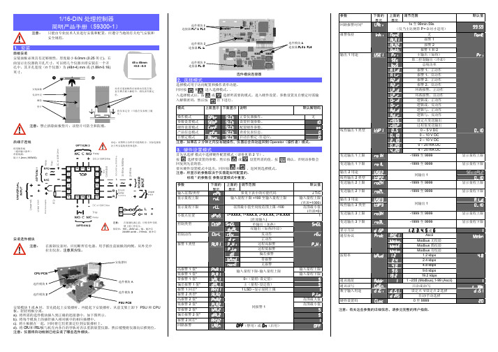
West P6010 1/16 DIN 数字显示器West P6010 可以进行多点测量,具有扣除毛重功能,更具灵活性。
它具有通用的输入,可显示为红色和绿色。
插入模块允许最多4个报警继电器(可以锁存或非锁存),PV 再传送或电源变送。
无需跳线 最小值/最大值保持 硬件自动监测 扣除毛重(自动归零)功能 最多4路报警输出 多点标定 Modbus 和 ASC II 通讯 计算机组态技术指标特点• 输出配置 最多 4 个输出,其中最多3个单路/1个双路继电器,最多1个PV 变送,最多1个变送器电源 • 报警类型 最多5个过程高/低报警、逻辑”或”报警(直接或反向操作)。
过程报警滞后可调。
• 可视变量 过程变量、最大值、最小值、上次复位后报警1的间隔时间。
• 人机界面 3 按键操作, 4 位 10mm 红色或绿色显示屏,3路报警指示,最大和最小值指示灯。
• 计算机组态 离线计算机组态(不需通讯选件)。
组态软件:Windows 98以上。
West 订货号:PS1-CON 输入• 热电偶 J 、K 、C 、R 、S 、T 、B 、L 、N & PtRh20%vsPtRh40% • RTD 3 线制 PT100,每线最大阻值50Ω(三线要平衡)。
• 线性直流 0-20/4-20mA ,0-50/10-50mV ,0-5/1-5/0-10/2-10V 。
量程 -1999 至 9999,小数点位置可调。
• 阻抗 热电偶和mV 输入时>10M Ω,V 输入时47k Ω,mA 输入时为5Ω。
• 精度输入量程的±0.1%,±1 LSD (热电偶输入时冷端补偿误差小于1°C )。
• 采样频率 每秒 4 次,精度 14 位。
• 传感器断线检测 <2秒(0-20mA 除外),热电偶和mV 输入时显示高报警,RTD 、mA 或V 输入时显示低报警。
输出和选件• 单路报警继电器 单刀双掷继电器 2 A ,240V (交流),>500,000 次。
WEST表P6100+_P8100+_P4100+简明用户手册

P24F
PtRh20% vs 40%: 32 - 3362 ºF
CC C: 0 - 2320 ºC
NC N: 0 - 1399 ºC
PTC Pt100: –199 - 800 ºC
CF C: 32 - 4208 ºF
NF N: 32 - 2551 ºF
PtF Pt100: –328 - 1472 ºF
296)
报警 1 和报警 2 的逻辑 “与” 运算,反向动作
)-#+ )-#4 /68* /6./ #<4.* 06./ /60/ 760/
中继给定值 SP 输出 中继实际值 PV 输出 0 到 5 伏直流输出 0 到 10 伏直流输出 2 到 10 伏直流输出 0 到 20 毫安直流输出 4 到 20 毫安直流输出
)3, ),,*
(标定范围下限 +100)到范围最大值之间 范围最小值到(标定范围上限 -100)之间
范围最大值 (线性参数=
1000) 范围最小值 (线性参数=
0)
小数点位置
94"+
/=XXXX, .=XXX.X, 0=XX.XX, :=X.XXX (仅适用于非温度的范围)
.*
控制类型
+%!, $;<4
若要安装模块 1、模块 A 或模块 B,首先请依次抬起上装配架和下装配架,从而让 PSU 电
路板和 CPU 电路板同前面板分离。分开电路板时请务必小心。
a. 将所需要的选件模块插入适当的连接器(如下所述)中。
b. 将模块的另一端对准相对板块上的有关插槽。
c. 同时抓住各个主机板,重新将它们放回到装配支架上。
LC L: 0 - 762 ºC LF L: 32 - 1403 ºF
WEST6100中文简明安装及操作说明书
3. MESSAGES/ERROR INDICATION(信息和错误指示)这些信息表明有错误发生,或者表明过程变量的信号或其线路有问题。
该信息只是提供帮助,并不能替代操作人员及安装人员的安全责任。
小心:请首先解决问题,然后再继续工作。
置后,将看到该屏幕。
按进入 Configuration(配)模式,接着按或继续4. 串行通讯有关详细信息,请参考完整的用户指南(可以向您的供应商索取)。
5. OPERATOR(操作员)模式在加电时会进入该模式,也可以从 Select(选择)模式进入。
注意:开始常规操作之前,必须根据应用的要求对所有的 Configuration(配置)模式和 Setup(设置)模式参数进行设置。
按滚动参数,然后按或设置所需要的值。
注意:显示策略 6 下的所有 Operator(操作员)模式参数均为只读(请参阅 Configuration(配置)模式中的 diSP),它们只能通过 Setup(设置)模式来进行调整。
上显示屏下显示屏显示策略及可见时间说明PV 值当前有效的 SP 值1 和 2(初始屏幕)PV 值和所选 SP 的目标值在显示策略 2 下可调整设定值PV 值实际的 SP 值 3 和 6(初始屏幕)PV 值和所选 SP 的实际值(比如斜坡时的SP 值)。
(只读)PV 值(空白)4(初始屏幕)仅显示过程变量。
(只读)当前有效的SP 值(空白)5(初始屏幕)仅显示设定值的目标值。
(只读)SP 值SP1,3,4,5和6所选 SP 的实际值。
只读实际的SP 值SPrp rP 不为OFF所选 SP 的实际(斜坡)值。
只读斜坡速率rpSpr 在设置模式中被使能SP斜率,单位/小时,可调(显示策略6除外)激活的报警状态ALSt当存在一个或多个活动报警时。
上行将显示ALM 并闪烁报警 2 激活L21 报警 1 激活回路报警激活警告报警被激活ALdG诊断故障报警123i1 = 如果输出1的记数报警动作2 =如果输出2的记数报警动作3 =如果输出3的记数报警动作i = 如果环境超温报警动作输出锁存报警被激活ALOL输出锁存报警OL1_ =锁存 输出1报警动作OL_2 =锁存 输出2报警动作OL12 =锁存 输出1或2报警动作程序段号SGnb程序运行状态下当前运行程序的程序段号(只读)目标设定值SGtS程序运行状态下当前程序段的目标设定值(只读)剩余时间SGtr程序运行状态下当前程序段剩余时间。
CN616TC1 电子流水桶控制器说明书
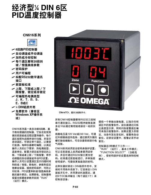
经济型1⁄4 DIN 6区PID温度控制器CN616系列是一类多功能6回路、基于微处理器的控制器,它旨在实现简便的前面板或远程设置和操作。
每个温区按照先后顺序进行扫描,并显示活动温区。
可锁定单个温区,以便进行监测。
每种仪器都可编程,以满足操作人员的以下需求:热电偶类型、温度单位、配置为锁定或非锁定的上限、下限或者上限/下限报警;带手动调整的自动调谐或手动PID设置。
操作人员可以设置温区显示扫描时间和斜坡/恒值。
断电时,参数和设定值都会保留。
提供密码保护,可防止对校准、PID设置和斜坡/恒值曲线参数的意外更改。
如果断电,控制器将保留全部最新参数并回到“RUN”(运行)模式。
所有CN616控制器都有RS232三线制串行通讯接口。
RS232程序能够监测多达10台通过菊花链连接在一起的仪器。
线路电压是120 Vac或240 Vac,可通过外部跳线组件选择。
通过使用方便的螺钉接线端插头,可在仪器背部进行电气连接。
CN616系列采用安全密码来保护设置。
可以在前面板上启用或者禁用该密码,并且可通过RS232接口更改密码。
校准通过前面板进行,并单独受密码保护。
可提供更高级别的密码。
这种仪器封装在1⁄4 DIN铝质外壳中,安装时不用将外壳拆下。
它安装在1⁄4 DIN 面板开孔中,并用滑动托架固定。
通过6个DC脉冲输出(每个温区1个)来控制该设备。
CN616系列U6回路PID控制器U自动调谐或手动调谐U加热或冷却控制U每个温区都有20段斜坡/恒值曲线参数U密码保护U用户可编程U标配RS232数字通讯接口U前面板校准U上限、下限或上限/下限报警,锁定或非锁定U可编程热电偶类型J、K、T、R、S、E、B或CU1⁄4 DIN铝质外壳U免费软件(兼容至Windows XP操作系统)CN616TC1,图片为实际尺寸。
提供一个单输出继电器,以指示任何温区中的报警条件。
该仪器通过闪烁主温度显示屏,同时闪烁报警温区编号来指示报警条件。
[WEST]P4100 P6100 P8100说明书
![[WEST]P4100 P6100 P8100说明书](https://img.taocdn.com/s3/m/e53fc6ec102de2bd9605880e.png)
5.1 上电步骤 .............................................................21
5.2 前面板及按键 .........................................................21
5.3 显示 21
7 操作模式 .................................................................................................................... 23
7.1 选择模式 .............................................................24
7.1.1
进入选择模式 ........................................................................................... 24
7.1.2
操作指南 ..................................................................................................24
5.4 LED 指示灯功能.......................................................22
6 故障显示 .................................................................................................................... 23
westP6100手册
模式
上面显示 下面显示 说明
默认解锁码
操作模式 参数设置模式
@/+ -!/@
-'3/ 正常仪器操作。 -'3/ 设置控制参数。
无
硬件设置模式
3 C"
-'3/ 配置硬件参数。
20
产品信息模式
C"
-'3/ 查看仪表信息。
自整定模式
/1C -'3/ 启动自整定/自适应。
注意:如果在 2 分钟之内没有键操作,仪器总会自动返回到 Operator(操作者)模式。
参数
输入范围/类型 显示量程上限
显示量程下限
小数点位置
控制类型
控制动作
报警 1 类型
高报警 1 值* 低报警 1 值* 带报警 1 值* 偏差报警 1 值* 报警 1 回差* 报警 2 类型* 高报警 2 值* 低报警 2 值* 带报警 2 值* 偏差报警 2 值* 报警 2 回差* 回路报警
下面的 显示 C)/
小心:该图所示为所有可能的组合。实际连接取 决于所安装的类型和选件。
注意: 在接通电源之前,应检查外壳铭 牌上的工作电压。
保险丝:100 – 240V ac – 1A,耐冲击 24/48V ac/dc – 315mA,耐冲击
安装选件模块
C注A意U:TION在: T拆ur卸n o仪ff表al时l p,ow应e切r. R断e所m有ov电e i源ns。tru用m手en抓t b住y前gr面ipp板in的g 两the侧s,id从es外of壳th中e front pane拉l a出nd仪p表ull。ing注th意e其in方str位um。ent out of its housing. Note its orientation.
P4100说明书[1]
![P4100说明书[1]](https://img.taocdn.com/s3/m/ffc785ea551810a6f52486cf.png)
PID 控制,带预整定、自整定、手动整定或 ON/OFF 控制功能。单加热输出或加热/冷却双输出。 可从前面板或通过数据输入进行选择,具有无扰切换功能。 最多 3 个输出,用于控制、报警、24V DC 变送电源或转发过程值或设定点。 过程高/低报警、设定值偏差报警、带报警、逻辑”与”/”或”报警。1 路回路报警用于过程控制安全。过程报 警滞后可调。 4 按键操作,两个 4 位 10mm 和 8mm LED 显示屏,可选择颜色(红色/红色、红色/绿色、绿色/红色、绿 色/绿色),5 个 LED 指示灯。 支持计算机组态(无需通讯选件)。组态软件适用于 Windows 98 及以上。West 订货号:PS1-CON。
2
红色上/绿色下
3
绿色上/红色下
电源
0
100-240V AC
2
24-48V AC 或 DC
选件插槽 A
0
无
1
RS485 通信
3
数字输入
4
远程设定点输入(基本型)
选件插槽 3
0
无
1
继电器
2
SSR(固态继电器)
3
DC 0-10V
4
DC 0-20mA
5
DC 0-5V
6
DC 2-10V
7
DC 4-20mA
8
可控硅驱动 直流或 SSR
继电器 选件 2
继电器 直流或 SSR 可控硅驱动
RS485 通讯
选件 1
数字量输入 1 电源输入
RSP 输入 (基本型)
选件 A
现场设置
输入 无跳线设置,可现场更改(不需要配件)
- 1、下载文档前请自行甄别文档内容的完整性,平台不提供额外的编辑、内容补充、找答案等附加服务。
- 2、"仅部分预览"的文档,不可在线预览部分如存在完整性等问题,可反馈申请退款(可完整预览的文档不适用该条件!)。
- 3、如文档侵犯您的权益,请联系客服反馈,我们会尽快为您处理(人工客服工作时间:9:00-18:30)。
8
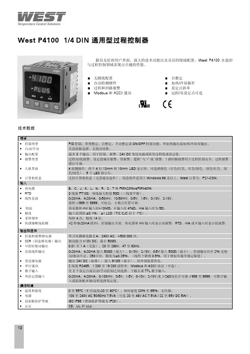
West P6100 1/16 DIN 通用型过程控制器
自动检测硬件 加热/冷却操作 过程和回路报警 设定点斜率 Modbus 和 ASCII 通讯 远程/双设定点可选
技术指标
单刀双掷继电器 2 A ,240V (交流),>500,000 次。
驱动能力 >10V DC ,最小 500。
0.01 至 1 A (交流),20 至 280V ,47 至 63Hz 。
West P6100
1/16 DIN 通用型过程控制器
9
选件3 变送输出 继电器 直流或SSR
直流或SSR 可控硅驱动 继电器
双继电器
选件2
功率输入
数字量输入
RSP 输入
直流或SSR
可控硅驱动
继电器 通用输入
热电偶
线性V/mV
线性mA
RSP 通讯
选件1
选件A
热电阻
选件3
外形尺寸
开孔尺寸
接线图
订货号
P6100
- x - x - x - x - x - x - x
输入类型
线制RTD 或直流mV 1 热电偶 2 DC mA 3 DC 电压 4 选件插槽 1 无 0 继电器
1 SSR (固态继电器)
2 DC 0-10V
3 DC 0-20mA
4 DC 0-5V
5 DC 2-10V
6 110mm
48mm 48m m。