隔离变压器 说明书.doc
医疗级隔离变压器产品说明说明书

Isolator Series 120V 500W UL 60601-1 Medical-Grade Isolation Transformer with 4 Hospital-Grade OutletsMODEL NUMBER:IS500HGDescriptionIsolator Series UL 60601-1 Listed Medical-Grade Isolation Transformers offer line isolation and continuous noise filtering. An internal low-impedance isolation transformer component offers 100%isolation from the input AC line. Full UL 60601-1 medical-grade listing with hospital-grade plug and outlet receptacles makes Isolator medical-grade transformers ideal for protecting sensitive electronic equipment in patient-care areas. Faraday shield reduces the cumulative leakage current of the Isolator and connected equipment to levels less than 100 microamps. Removes EMI/RFI noise, utility switching transients and harmonics generated by other on-site loads. Reduces impact of utility-related surge conditions. Transformer filtering provides continuous common-mode noise rejection with no wearableparts. Reduces 6000V IEEE587 Category A & B ring wave and combination wave test surges to only 0.5V common mode. Includes four widely spaced NEMA 5-15R hospital-grade output receptacles, 10-ft. (3.05m) power cord, hospital-grade input plug, circuit breaker overload protection, lighted power switch and rugged all-metal housing. Ships ready for placement in any industrial, medical, office or networkenvironment. PLUG/OUTLETS: Input - NEMA 5-15P Hospital Grade; Output - 4 NEMA 5-15R Hospital Grade ELECTRICAL: 120V AC, 60 Hz, 4.2A (requires NEMA 5-15R wall receptacle).FeaturesOffers line isolation and continuous noise filteringq Internal low-impedance isolation transformer with Faraday shield offers 100% isolation from the input AC lineqFull UL 60601-1 medical-grade listing with hospital-grade plug and outlet receptacles for the protection of sensitive electronic equipment in patient-care areasqReduces cumulative leakage current of the Isolator and connected equipment to levels less than 100 A q Floating AC output prevents noise coupling from noisy hospital ground circuits q Inexpensive alternative to dedicated circuits and site electrical upgradesq Removes EMI/RFI noise, utility switching transients, load-generated harmonics and ground loops q Transformer filtering offers continuous common-mode noise rejection with no wearable partsq Reduces 6000V IEEE587 Cat A & B ring wave and combination wave test surges to only 0.5V common modeqIncludes 4 widely spaced NEMA 5-15R hospital-grade output receptacles, 10-ft. (3.05 m) power cord,hospital-grade input plug, circuit breaker overload protection, lighted power switch and rugged all-metalqHighlightsComplete line isolation & noise filteringqHospital-grade plug and receptaclesqLowers cumulative leakagecurrent of connected equipment to under 100 AqFloating AC output prevents noise coupling qTAA-compliantqPackage IncludesIS500HG Isolation Transformer q Instruction manual with warranty informationqSpecificationsunit housingShips ready for upright tower placement in any industrial, medical, office or network environmentq© 2023 Eaton. All Rights Reserved. Eaton is a registered trademark. All other trademarks are the property of their respective owners.。
KBSG-150变压器使用说明书

KBSG-150/3.3
矿用隔离变压器
使用说明书
产品型号:KBSG-150/3.3
容量:150KV A
西安康瑞矿用设备有限公司
一、产品使用环境条件
1.1 环境温度:-25℃~ +40℃
1.2 海拔高度不超过1000m
1.3 相对温度:不大于95%,无凝露现象
1.4 必须安装在有循环水冷却的隔爆箱体内方可在煤矿井下使用
二、主要技术参数
额定电压:高压侧:3300V
低压侧:400V
额定容量:150KV A
连接组别号:DY11
阻抗电压:3~4%
频率:50Hz
相数: 3
绝缘等级:H级
冷却方式:隔爆箱体循环水冷却
三、使用、保管注意事项
1.使用前应检查紧固件是否松动,铁轭螺杆,夹件与铁芯间的绝缘是
否良好,引线是否损坏。
2.使用前用1000V~2500V兆欧表检查各绕组之间和各绕组对地的绝
缘电阻值均应大于5兆欧。
3.温度开关两线间的电阻值为零,Pt100热电阻的电阻值约为110Ω。
使用前注意检查,防止出现接线错误。
4.使用前必须将变压器铁芯底部的防锈脂去除。
5.吊装时最好使用专用U型吊装环,以免铁芯损坏。
6.变压器保管期间应防潮、防雨、防撞击。
7000W 230V 隔离变压器说明书
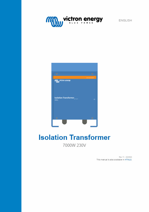
ENGLISHIsolation Transformer7000W 230VRev 11 - 02/2023This manual is also available in HTML5.Table of Contents1. Safety Instructions (1)2. Features (2)2.1. Electrical safety (2)2.2. Galvanic corrosion prevention (2)2.3. Converting voltages (3)2.4. Soft start (3)2.5. Internal wiring diagram (3)2.6. Safety when the vessel is out of the water (3)3. Installation (4)3.1. What's in the box (4)3.2. Connections overview (4)3.3. Connecting AC input and AC output (5)3.4. AC output neutral to earth link (5)3.5. Cable cross-section requirements (6)3.6. Wiring example (6)3.7. Linking input and output earth when the vessel is out of the water. (6)4. Operation (8)4.1. Inrush current limiter (8)4.2. Temperature protection (8)5. Technical specifications (9)6. Dimensions (10)WARNING: Before installing, using, storing or transporting this product, read and save the safety instructionsbelow.General:•Review the related documentation of this product to familiarise yourself with safety markings andinstructions before operating the equipment. This product has been designed and tested in accordance withinternational standards. Only use the equipment for the intended purpose of application and in accordancewith the specifications as stated in the Technical specification chapter.•WARNING: RISK OF ELECTRIC SHOCK.•Do not open the enclosure if the product is still connected to an electrical power source.•Do not remove the front panel or operate the product without all panels fitted. Refer all servicing to qualifiedpersonnel.•Caution: never carry heavy loads without assistance.•Do not expose the product to water, mist, snow, spray, or dust.•Do not use the product in locations where there is a risk of gas or dust explosions. This product is notignition protected.Installation:•Always refer to the installation section in the manual before applying power to the equipment.•Connections, cable sizes and safety features must be according to the locally applicable regulations.•This is a safety class I product (provided with a protective earthing terminal). An uninterruptible safetyearth ground must be provided at the AC-in and AC-out terminals. An additional grounding point is locatedat the outside of the product. Whenever it is likely that the grounding protection has been impaired, theproduct must be made inoperative and secured against any unintended operation; refer to qualified servicepersonnel.•Make sure that circuit breakers are provided in the connecting wires. Never replace a safety componentwith a different type. Consult the manual to determine the correct component.•Before applying power, verify that the available power source matches the configuration settings of theproduct as described in the manual.•Ensure that the environmental conditions are suitable for the operation of the equipment. Never operatethe product in the rain or a dusty environment. Allow at least 10cm of free space around the product forventilation, and ensure that ventilation fans are not blocked. Install in a well-ventilated and heat-resistantenvironment. Avoid the presence of, e.g. chemicals, synthetic components, curtains or other textiles in theimmediate vicinity of the product.•Be sure that the demanded power does not exceed the product's power rating.Transport and storage:•When storing or transporting the product, make sure that all mains power leads are disconnected.•No liability can be accepted for any transport damage when equipment is shipped in non-original packaging.•Store the product in a dry location. Storage temperature must be between -20°C and 60°C.The isolation transformer eliminates any electrical continuity between AC shore power and the vessel. It is essential for safety and eliminates the need for galvanic isolators and polarity alarms.2.1. Electrical safetyElectrical safety is taken for granted in the case of a standard on-shore installation. A circuit breaker will trip, or a GFCI (Ground Fault Circuit Interrupter) will trip in case of a short circuit or a current leakage to ground. Connecting the ground wire of theshore-side supply to a vessel's metal parts will result in galvanic corrosion.Bringing only the live and neutral wire onboard results in an unsafe situation because GFCIs will not work, nor will a breaker trip in case of a short circuit to a metal part on the vessel.2.2. Galvanic corrosion preventionGalvanic corrosion occurs when two dissimilar metals in electrical contact are simultaneously exposed to an electrically conducting fluid. Seawater and, to a lesser extent, freshwater are such fluids. In general, the more active alloy of the couple corrodes preferentially, while the less active (more noble) material is cathodically protected. The rate of galvanic corrosion is a function of several variables, including area ratios, the conductivity of the fluid, temperature, the nature of the materials, etc.It is a misunderstanding that galvanic corrosion occurs only in metal and aluminium hulls. In fact, it can occur on any vessel as soon as a metallic part (the shaft and propeller) is in contact with water. Galvanic corrosion will quickly dissolve your sacrificial anodes and attack the shaft, propeller and other metal parts in contact with water when the vessel is connected to the shore-side supply. It might therefore be tempting not to connect the ground conductor: this is, however, extremely dangerous because a GFCI will not work, nor will a circuit breaker trip in case of a short circuit to a metal part on the vessel.The best solution to avoid galvanic corrosion and, at the same time, prevent any unsafe situation is to install an isolation transformer to connect to the shore-side supply. The isolation transformer eliminates any electrical continuity between shore power and the vessel. The shore power is fed to the transformer's primary side, and the vessel is connected to the secondary. The isolation transformer completely isolates the vessel from the shore ground. By connecting all metal parts to the neutral output on the secondary side of the transformer, a GFCI or a breaker will trip in case of a short circuit.The shore ground connected to immersed metals of the vessel causesgalvanic corrosion.The shore ground is isolated from the vessel ground, and galvaniccorrosion originating from the shore connection is blocked.2.3. Converting voltagesThe isolation transformer converts the input voltage with a 1:1.05 ratio. The 1:1.05 transformer ratio boosts the output voltage of the isolation transformer by 5%. This is to compensate for shore power voltage drops that are a common occurrence in marinas.• A 230V input becomes 240V.The isolation transformer can be used in 50Hz or 60Hz systems. However, the isolation transformer cannot convert frequencies from 50Hz to 60Hz or vice versa.2.4. Soft startSoft start is a standard feature of a Victron Energy isolation transformer. It will prevent the shore power circuit breaker from tripping due to the transformer inrush current.2.5. Internal wiring diagramInternal wiring diagram of the isolation transformer.2.6. Safety when the vessel is out of the waterIt is recommended, for optimal safety, to connect the shore earth to the vessel's earth when the vessel is out of the water, in winter or for maintenance. The isolation transformer has a facility for this.3.1. What's in the boxThe isolation transformer ships with the following items:3.2. Connections overviewThe Earth link wires used in points 2 and 4 are included with the transformer. They have a core surface areaof 6mm² (10AWG) and are connected to a 6.3mm spade terminal. Depending on local electrical regulations,this cable surface area might not be large enough to carry the potential fault currents of the AC systemwhere the isolation transformer is used. If wires with a larger core surface area are required, then do not usethe jumper connections but make the connections between the AC input and/or AC output terminal instead.Alternatively, make these connections external from the isolation transformer.3.3. Connecting AC input and AC outputShock hazard. Do not work on the isolation transformer or the electrical system if still connected to anelectrical power source.Connection sequence:1.Pass the AC cables through the cable glands at the bottom of the cabinet in the following way:a.Pass the AC input (shore power) cable through the left side cable gland.b.Pass the AC output (AC loads) cable through the right side cable gland.2.Connect the AC input cable to the INPUT terminal block in the following way:a.Connect the earth wire to the PE terminal.b.Connect the neutral wire to the N terminal.c.Connect the phase wire to the L terminal.3.Connect the AC output cable to the OUTPUT terminal block in the following way:a.Connect the earth wire to the PE terminal.b.Connect the neutral wire to the N terminal.c.Connect the phase wire to the L terminal.4.Connect the enclosure to the ground (=all the metal parts in the vessel) in the following way:a.Connect the M6 bolt underneath the enclosure to the vessel ground. See the below drawing for the location of the chassisearth bolt.Location of the chassis earth bolt.3.4. AC output neutral to earth linkA GFCI must be installed in the AC output of the isolation transformer. For the GFCI to operate correctly, the AC output neutral must be connected to the AC output earth and ground (= all the metal parts in the vessel).To link the AC output neutral (N) to earth (PE), place a green/yellow jumper wire (included) between male spade connectors J5 and J7.AC output neutral (N) to earth (PE) link.3.5. Cable cross-section requirementsUse the following minimal cable cross-sections:3.6. Wiring exampleWiring example isolation transformer installed on a vessel connected to shore power.3.7. Linking input and output earth when the vessel is out of the water.For safety reasons, when the vessel is out of the water (on land) during winter or for maintenance, the vessel earth (PE) conductor must be connected directly to the shore power earth (PE) conductor.This can be achieved inside the isolation transformer by connecting the yellow/green jumper wire (included) between the male spade connectors J12 and J9, as indicated below.AC input earth is connected to AC output earth when the vessel is out of the water (on land) during winter or for maintenance.Check the input and output voltage configuration before operating the isolation transformer.4.1. Inrush current limiterThe inrush current limiter prevents upstream circuit breakers from tripping when switching on the isolation transformer.4.2. Temperature protectionThe isolation transformer is fan cooled. The fan speed is temperature-controlled. Its speed (rpm) will increase if the temperature increases.The isolation transformer is protected against overtemperature and will switch off in case of overheating.。
海利普变频器产品说明书

海利普企业简介营销服务网络图*图注红:销售服务中心蓝:办事处浙江海利普电子科技有限公司成立于2001年,于2005年纳入Danfoss旗下,成为其全资子公司。
丹佛斯是丹麦最大的跨国工业制造公司,创立于 1933年,丹佛斯以推广应用先进的制造技术,并关注节能环保而闻名于世,是制冷和空调控制,供热和水控制,以及传动控制等领域处于世界领先地位的产品制造商和服务供应商。
在过去的10年中,海利普经历了巨大的变化,已发展成一家集研发、生产、销售于一体的国家级高新技术企业,同时也是国内唯一一家拥有省级变频研发中心的企业。
海利普是目前中国最大的变频器生产厂家,其核心产品HLP系列变频器,广泛应用于起重、纺织、印染 、石油、化工、建筑、建材、橡胶、塑料、包装、印刷、造纸、食品、饮料、环保、水处理、机床等行业,先后被列入“国家重点新产品”、 “国家火炬计划项目”,并于2004年被授于“浙江省名牌产品”、“国内最具有竞争力的产品”。
为了适应丹佛斯在中国建立第二家乡市场的战略,海利普依靠丹佛斯的强大支持,寻求高速发展,更加巩固了海利普在中国变频器领域的领先地位,同时逐渐成为丹佛斯旗下的能源电子部在亚太地区的制造和物流中心。
公司愿景:比市场增长更快,成为中国市场品质最高的知名品牌。
目录通用型变频器HLP-A通用型变频器 / 4HLP-C+迷你型变频器 / 12矢量型变频器HLP-B高性能矢量型变频器/ 17HLP-NV矢量型变频器 / 24专用型变频器HLP-P风机/水泵专用变频器 / 30 HLP-H中频机 / 36HLP-F纺织专用变频器 / 40HLP-J注塑机专用变频器 / 43HLP-CP跑步机/手套机专用变频器 / 47 HLP-M机床专用变频器 / 51常用选配件直流电抗器 / 55交流输入/输出电抗器 / 55输入/输出滤波器 / 57制动单元与制动电阻 / 57接线用断路器及漏电开关 / 58电磁接触器及浪涌吸收器 / 59隔离变压器 / 59 海利普变频器 系列产品本产品为通用型变频器,软件功能强大,具有多种控制方式;内置PID、简易PLC;输出转矩高(150%/1分钟),过载能力强,广泛应用于编织、化纤、印染、塑料、轻工、机械、化工、钢铁、造纸等各种行业,并受到用户的一致好评。
隔离变压器 说明书.doc
隔离变压器
使用说明书
一、概述:
隔离变压器系根据国家标准《GB6450-86》、《GB9554-87》及《BJ297-78》设计制造。
二、用途:
本产品作为负载与电力网隔离设备及升降压,广泛应用于发电厂、电力系统、工矿、交通企业的负荷与电力网需电气隔离的场所作电源用,是自动控制系统、通讯调度网络、计算机设备、精密测量试验系统的净化(抗干扰)之必备设备。
三、特点:
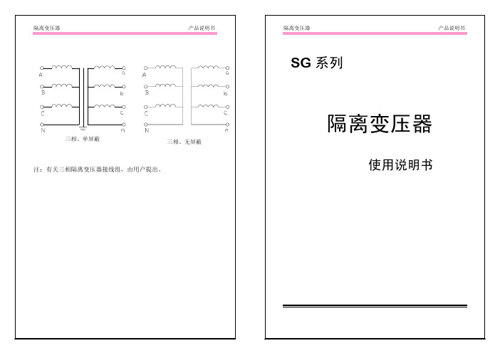
1、SG系列隔离变压器采用优质冷轧硅钢片、高强度绝缘漆包线和SBECB双玻璃丝包线及E、H级绝缘材料制造,防护式产品按TP2X 级的要求设计外壳。
2、本产品分无屏蔽的单、双屏蔽三种,除前者防止一、二次电压互窜外,还可抑制一次侧的杂波对二次侧的影响。
3、该产品为干式防护式外壳,体积小、重量轻、安装使用方便、适用于固定、移动的场合。
四、使用条件:
1、海拔高度不超过1000米。
2、环境温度不超过45℃,相对湿度不大于85%。
3、使用场地应无水蒸汽、腐蚀气体及易燃易爆炸性介质。
bxg3-35隔离变压器说明书

bxg3-35隔离变压器说明书摘要:1.概述2.产品特点3.工作原理4.产品规格5.应用范围6.安装与维护7.安全注意事项正文:【概述】bxg3-35 隔离变压器是一种常用的电力设备,主要用于电压的变换和隔离。
它能够将高压电转换为低压电,以满足不同电气设备的电压需求,同时,它还能隔离电路,保证人身安全和设备的稳定运行。
【产品特点】bxg3-35 隔离变压器具有以下特点:1.结构紧凑,体积小,安装方便。
2.效率高,损耗低,节能环保。
3.抗干扰能力强,对电源电压的波动有较好的抑制作用。
4.采用优质材料,具有良好的耐热性和抗老化性能。
【工作原理】bxg3-35 隔离变压器的工作原理是利用电磁感应,将输入的高压电压通过变换器降低到所需的低压电压,同时,变换器与负载之间设有隔离层,有效地隔离了电路,保护了人身安全和设备的稳定运行。
【产品规格】bxg3-35 隔离变压器的主要规格如下:1.输入电压:35kV2.输出电压:380V/220V3.额定容量:500kVA4.效率:≥98%5.空载电流:≤5%【应用范围】bxg3-35 隔离变压器广泛应用于以下领域:1.住宅小区、商业建筑等民用建筑的电力设备。
2.工厂、矿山等工业企业的电力设备。
3.机场、火车站、医院等公共设施的电力设备。
【安装与维护】1.安装前,应检查设备是否完好,安装位置是否合适,确保安装环境干燥、通风。
2.安装时,应按照设备说明书进行,确保接线正确,螺丝紧固。
3.设备运行中,应定期检查设备的温度、声音等,发现异常应及时停机检查。
4.定期对设备进行清洁和维护,确保设备的正常运行。
【安全注意事项】1.在使用设备时,应确保电气设备完好,电源电压稳定。
2.在设备运行中,严禁触碰设备,防止触电。
3.在设备维护时,应先停机,切断电源,确保人身安全。
7000W 230V 隔离变压器 Rev 11 - 02 2023说明书
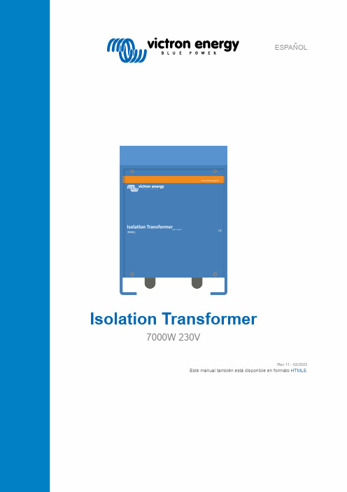
ESPAÑOLIsolation Transformer7000W 230VRev 11 - 02/2023Este manual también está disponible en formato HTML5.Tabla de contenidos1. Instrucciones de seguridad (1)2. Características (2)2.1. Seguridad eléctrica (2)2.2. Prevención de la corrosión galvánica (2)2.3. Conversión de tensiones (3)2.4. SoftStart (arranque suave) (3)2.5. Diagrama de cableado interno (3)2.6. Seguridad cuando el barco está fuera del agua (3)3. Instalación (4)3.1. ¿Qué hay en la caja? (4)3.2. Descripción de las conexiones (4)3.3. Conexión de entrada y salida de CA (5)3.4. Enlace del neutro de la salida CA a tierra. (6)3.5. Requisitos relativos a la sección del cable (6)3.6. Ejemplo de cableado (7)3.7. Enlace de la tierra de la entrada y la salida cuando el barco está fuera del agua. (7)4. Funcionamiento (9)4.1. Limitador de corriente de irrupción (9)4.2. Protección térmica (9)5. Especificaciones técnicas (10)6. Dimensiones (11)ADVERTENCIA: Antes de instalar, utilizar, guardar o transportar este producto, lea y guarde estasinstrucciones de seguridad.General:•Revise los documentos de este producto para familiarizarse con las indicaciones de seguridad y lasinstrucciones antes de manejar el equipo. Este producto ha sido diseñado y comprobado de acuerdo conlas normas internacionales. Utilice el equipo únicamente para el fin previsto y siempre de conformidad conlas especificaciones recogidas en el apartado de Especificaciones técnicas.•ADVERTENCIA: RIESGO DE DESCARGA ELÉCTRICA.•No abra la carcasa si el producto sigue conectado a una fuente de energía eléctrica.•No retire el panel frontal ni encienda el producto si no están colocados todos los paneles. Recurra apersonal cualificado para cualquier reparación.•Precaución: nunca levante cargas pesadas sin ayuda.•No exponga el producto a agua, vaho, nieve, rocío, pulverización o polvo.•No utilice el producto en lugares con riesgo de explosión de gas o polvo. Este producto no es ignífugo. Instalación:•Antes de conectar el equipo a la corriente respete siempre lo indicado en el apartado de instalación delmanual.•Tanto las conexiones, como las dimensiones de los cables y las medidas de seguridad deben ajustarse a lanormativa local aplicable.•Este producto es de clase de seguridad I (suministrado con un terminal de puesta a tierra de protección).Se debe disponer de una puesta a tierra de protección permanente en los terminales de entrada y salidade CA. Hay otro punto de puesta a tierra adicional en la parte exterior del producto. Si sospecha que lapuesta a tierra está deteriorada, deberá dejar el equipo inoperativo y asegurarse de que no se puede poneren marcha de forma accidental. A continuación, póngase en contacto con personal técnico cualificado.•Compruebe que hay disyuntores en los cables de conexión. No sustituya nunca un componente deseguridad con uno de otro tipo. Consulte el manual para determinar cuál es el componente adecuado.•Antes de conectarlo a la corriente, compruebe que la fuente eléctrica disponible coincide con laconfiguración del producto descrita en el manual.•Asegúrese de que las condiciones ambientales son adecuadas para el funcionamiento del equipo. Nuncautilice el producto bajo la lluvia o en un entorno polvoriento. Deje al menos 10 cm de espacio libre alrededordel producto para su ventilación y asegúrese de que los ventiladores no están bloqueados. Instale launidad en una zona bien ventilada y protegida del calor. Debe evitarse la presencia de productos químicos,componentes sintéticos, cortinas u otros textiles en su proximidad.•Asegúrese de que la potencia demandada no supera la potencia nominal del producto.Transporte y almacenamiento:•Cuando guarde o transporte el producto, compruebe que todos los cables de alimentación a la red estándesconectados.•No se aceptará ninguna responsabilidad por cualquier daño ocasionado al equipo durante el transporte sieste no lleva su embalaje original.•Guarde el producto en un lugar seco. La temperatura de almacenamiento debe estar entre -20 °C y 60 °C.El transformador de aislamiento elimina la continuidad eléctrica entre la alimentación del puerto y la embarcación. Es fundamental para la seguridad y elimina la necesidad de aislamiento galvánico y alarmas de polaridad.2.1. Seguridad eléctricaLa seguridad eléctrica se da por garantizada en las instalaciones estándares de los puertos. Saltará un disyuntor o un interruptor de circuito de fallo de puesta a tierra (GFCI) en caso de cortocircuito o fugas de corriente a la conexión a tierra. Al conectarel cable de conexión a tierra de la alimentación del puerto a las partes metálicas de la embarcación, se producirá corrosióngalvánica.Pero llevar solo los cables con corriente y neutro a bordo genera una situación insegura porque los interruptores de circuito de fallo de puesta a tierra (GFCI) no funcionarán y tampoco saltará el disyuntor en caso de cortocircuito en alguna parte metálica de la embarcación.2.2. Prevención de la corrosión galvánicaLa corrosión galvánica se produce cuando dos metales distintos en contacto eléctrico se exponen simultáneamente a un líquido conductor de electricidad. El agua de mar y, en menor medida, el agua dulce, son líquidos de este tipo. En general, la aleaciónmás activa de los dos se corroe antes, mientras que el material menos activo (más noble) tiene protección catódica. El gradode corrosión galvánica depende de diferentes variables, como la relación de áreas, la conductividad del fluido, la temperatura, la naturaleza de los materiales, etc.Se cree erróneamente que solo los cascos de metal y aluminio sufren corrosión galvánica. De hecho, puede darse en cualquier embarcación en el momento en que una pieza metálica (el eje y la hélice) entra en contacto con el agua. La corrosión galvánica disolverá rápidamente los ánodos de sacrificio y atacará el eje, la hélice y otras partes metálicas que estén en contacto conel agua cuando el barco esté conectado a la alimentación del puerto. Puede resultar tentador no conectar el conductor de conexión a tierra, pero esto es extremadamente peligroso porque los interruptores de circuito de fallo de puesta a tierra (GFCI) no funcionarán, y tampoco saltará el disyuntor en caso de cortocircuito en alguna parte metálica de la embarcación.Lo mejor para evitar la corrosión galvánica y, al mismo tiempo, evitar cualquier situación de inseguridad, es instalar un transformador de aislamiento para conectarse a la alimentación del puerto. El transformador de aislamiento elimina la continuidad eléctrica entre la alimentación del puerto y la embarcación. La alimentación del puerto se conecta a la parte primaria del transformador y la embarcación se conecta a la secundaria. El transformador de aislamiento aísla completamente el barco de la conexión a tierra del puerto. Al conectar todas las partes metálicas a la salida neutra de la parte secundaria del transformador, en caso de cortocircuito, saltará un interruptor de circuito de fallo de puesta a tierra (GFCI) o un disyuntor.La conexión a tierra del puerto conectada alos metales sumergidos del barco producecorrosión galvánica.La conexión a tierra del puerto está aislada de laconexión a tierra del barco, de modo que la corrosióngalvánica que se origina en la conexión al puerto quedabloqueada.2.3. Conversión de tensionesEl transformador de aislamiento convierte la tensión de entrada con una ratio de 1:1,05. La ratio de 1:1,05 del transformador incrementa un 5 % la tensión de salida del transformador de aislamiento. De este modo se compensan las caídas de tensión de la alimentación del puerto que se producen con frecuencia en los puertos.•Una entrada de 230 V se convierte en 240 V.El transformador de aislamiento puede usarse en sistemas de 50 Hz o 60 Hz. Sin embargo, el transformador de aislamiento no puede convertir frecuencias de 50 Hz a 60 Hz ni al revés.2.4. SoftStart (arranque suave)El arranque suave es una característica estándar de los transformadores de aislamiento de Victron Energy. Evitará que el disyuntor de la alimentación del puerto salte debido a la corriente de irrupción del transformador.2.5. Diagrama de cableado internoDiagrama de cableado interno del transformador de aislamiento.Identificación ABCDEFG2.6. Seguridad cuando el barco está fuera del aguaSe recomienda, para que las condiciones de seguridad sean óptimas, conectar la puesta a tierra del puerto a la del barco cuando el barco esté fuera del agua, durante el invierno o por tareas de mantenimiento. El transformador de aislamiento cuenta con una instalación para ello.3.1. ¿Qué hay en la caja?El transformador de aislamiento se entrega con los siguientes artículos:3.2. Descripción de las conexionesLos cables de enlace de puesta a tierra usados en los puntos 2 y 4 se incluyen con el transformador. Tienen un núcleo con una sección de 6 mm² (10 AWG) y están unidos a un conector Faston de 6.3 mm. En función de la normativa eléctrica local, esta sección de cable puede no ser lo suficientemente grande para llevar las posibles corrientes de fallo del sistema CA en el que se usa el transformador de aislamiento. Si se necesitan cables con una sección de núcleo mayor, no use las conexiones puente y haga las conexionesentre la entrada CA y/o la salida CA. Otra opción es hacer estas conexiones de forma externa con respecto al transformador de aislamiento.3.3. Conexión de entrada y salida de CAPeligro de descarga eléctrica. No trabaje en el transformador de aislamiento o en el sistema eléctrico estandoconectado a una fuente de energía eléctrica.Secuencia de conexión:1.Pase los cables CA a través de los pasacables de la parte inferior del armario del siguiente modo:a.Pase el cable de entrada de CA (alimentación del puerto) a través del casquillo pasacables de la izquierda.b.Pase el cable de salida de CA (cargas CA) a través del casquillo pasacables de la derecha.2.Conecte el cable de entrada CA al bloque terminal INPUT (entrada) del siguiente modo:a.Conecte el cable de puesta a tierra al terminal PE.b.Conecte el cable neutro al terminal N.c.Conecte el cable de fase al terminal L.3.Conecte el cable de salida CA al bloque terminal OUTPUT (salida) del siguiente modo:a.Conecte el cable de puesta a tierra al terminal PE.b.Conecte el cable neutro al terminal N.c.Conecte el cable de fase al terminal L.4.Conecte la carcasa a tierra (= todas las partes metálicas del barco) del siguiente modo:.a.Conecte el perno M6 de la parte inferior de la carcasa a la conexión a tierra del barco. En el siguiente dibujo puede ver laubicación del perno de la tierra del chasis.Ubicación del perno de la tierra del chasis.3.4. Enlace del neutro de la salida CA a tierra.Debe instalarse un interruptor de circuito de fallo de puesta a tierra (GFCI) en la salida CA del transformador de aislamiento. Para que el interruptor de circuito de fallo de puesta a tierra (GFCI) funcione correctamente, el neutro de salida CA deberáconectarse a la tierra de la salida CA (= todas las partes metálicas del barco).Para enlazar el neutro de la salida CA (N) a tierra (PE), coloque un cable puente verde/amarillo (incluido) entre los conectores Faston macho J5 y J7.Enlace del neutro de la salida CA (N) a tierra (PE).3.5. Requisitos relativos a la sección del cableUtilice las siguientes secciones de cable mínimas:3.6. Ejemplo de cableadoEjemplo de cableado de transformador de aislamiento instalado en un barco conectado a la alimentación del puerto.Por motivos de seguridad, cuando el barco está fuera del agua (en tierra) durante el invierno o para realizar tareas de mantenimiento, el conductor de tierra (PE) del barco debe conectarse directamente al conductor de tierra de la alimentación del puerto (PE).Esto puede hacerse dentro del transformador de aislamiento conectando el cable puente verde/amarillo (incluido) entre losconectores Faston macho J12 y J9 como se indica a continuación.durante el invierno o para realizar tareas de mantenimiento.Compruebe la configuración de la tensión de entrada y de salida antes de operar el transformador deaislamiento.4.1. Limitador de corriente de irrupciónEl limitador de corriente de irrupción evita que los disyuntores salten al encender el transformador de aislamiento.4.2. Protección térmicaEl transformador de aislamiento se refrigera mediante ventilador. La velocidad del ventilador se controla a través de la temperatura. Su velocidad (rpm) aumentará si sube la temperatura.El transformador de aislamiento está protegido del exceso de temperatura y se apagará en caso de sobrecalentamiento.。
致远电子股份有限公司 ZCM25XX 系列信号隔离变送模块数据手册说明书
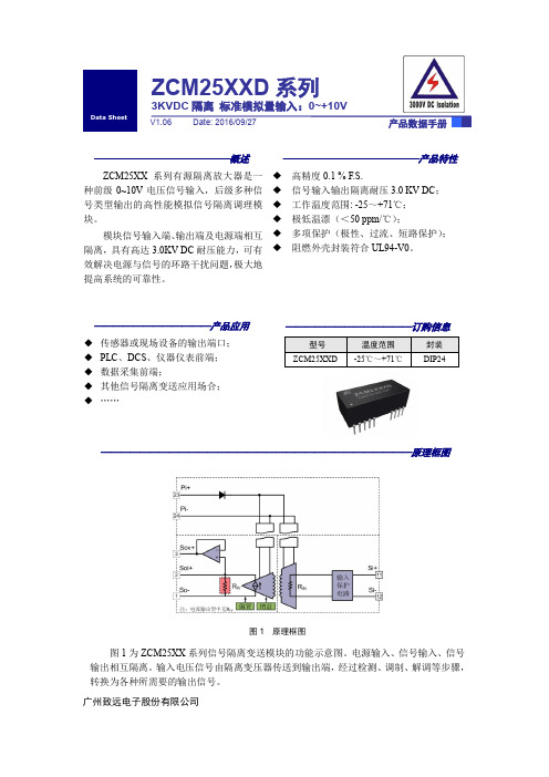
——————————————概述ZCM25XX 系列有源隔离放大器是一种前级0~10V 电压信号输入,后级多种信号类型输出的高性能模拟信号隔离调理模块。
模块信号输入端、输出端及电源端相互隔离,具有高达3.0KV DC 耐压能力,可有效解决电源与信号的环路干扰问题,极大地提高系统的可靠性。
——————————————产品特性◆高精度0.1 % F.S.◆信号输入输出隔离耐压3.0 KV DC ;◆工作温度范围: -25~+71℃;◆极低温漂(<50 ppm/℃);◆多项保护(极性、过流、短路保护);◆阻燃外壳封装符合UL94-V0。
ZCM25XXD 系列3KVDC 隔离 标准模拟量输入:0~+10V广州致远电子股份有限公司————————————————————————————————原理框图图1 原理框图ZCM25XX 系列信号隔离变送模块的功能示意图。
电源输入、输入电压信号由隔离变压器传送到输出端,经过检测、转换为各种所需要的输出信号。
修订历史1. 电气参数 (1)1.1参数特性表 (1)2. 产品列表 (2)3. 典型应用 (3)3.1信号隔离与转换 (3)3.2信号远距离传输与隔离 (3)3.3多路信号输出 (3)4. 引脚信息 (5)5. 机械尺寸 (6)5.1封装尺寸 (6)5.2PCB布板图 (6)5.3包装信息 (7)6. 免责声明 (8)1.1 参数特性表表 1.1 特性参数注:F.S.=Full Scale 满量程表2.1 产品列表3. 典型应用3.1 信号隔离与转换ZCM25XX系列隔离变送器能够很好地用在需要信号隔离与变换的场合。
它能够将0~10V电压信号隔离转换成为各种类型的信号,提供给PLC、DCS、AD和仪器仪表使用,如图3.1所示。
图3.1 隔离转换应用场合3.2 信号远距离传输与隔离结合ZCM20XX系列,可以组成工业标准4~20mA电流环,保证高精度的远距离传输同时,实现传感器与控制器的双隔离保护,如图3.2所示。
K11,K13,K20隔离变压器主要用途

K11,K13,K20隔离变压器主要用途隔离变压器是扬州志力公司多年来采用优质材料和先进的工艺技术而生产,具有防潮、维护方便等优点,能深入负荷中心,可用于地铁、高层建筑、机场、车站、码头、企业及隧道等输配电场所。
K11,K13,K20隔离变压器主要用于交流50—60Hz,电压不超过500V的各种供电场所、产品的各种输入、输出电压、联接组别、抽头线组容量的分配,均可根据用户要求进行精心设计与制造。
K11,K13,K20隔离变压器加装在稳压电源的典型应用一、在电源输入端接入K11 K13 K20隔离变压器(三角/星形)1、若电网三次谐波和干扰信号比较严重,采用△/Yo隔离变压器,可以去掉三次谐波和减少干扰信号。
2、可以采用△/Yo隔离变压器产生新的中性线,使设备与电网中性线无关,避免由于电网中性线不良造成设备运行不正常。
3、非线性负载引起的电流波形畸变(如三次谐波)可被隔离而不污染电网。
二、在电源输出端接入隔离变压器(星形/三角)1、防止非线性负载的电流畸变,影响到稳压电源的正常工作及反回到电网,起到净化电网的作用。
2、非线性负载电流的畸变影响取样的准确性,可以在Yo/△隔离变压器输入端采样,得到能反应实际情况的控制信号,使稳压电源控制正常。
3、若负载不平衡,采用Yo/△也不影响稳压电源的正常工作。
三、K11,K13,K20隔离变压器技术指标1 输入额定电压:三相380V或单相220V2 工作频率:50Hz-60Hz3 效率:≥98%4 温升:<85℃5 波形畸变:<0.1%6 绝缘强度:3000V,1分钟无击穿7 绝缘电阻:绕阻对地绝缘电阻三相≥3.8M欧米茄;单相≥2.2M欧米茄四,使用条件1 适用海拔高度:≤5000m2 环境温度:-15℃~+40℃3 相对湿度:≤85%4 安装场所应无严重影响稳压器绝缘强度的气体,蒸汽,化学性沉积,污垢,导电尘埃及无其他易爆易燃易腐蚀的物质。
5 凡不符合上述使用条件的,应与我们协商确定。
致远电子有限公司定压输入隔离6KVDC非稳压单输出2W系列产品数据手册说明书
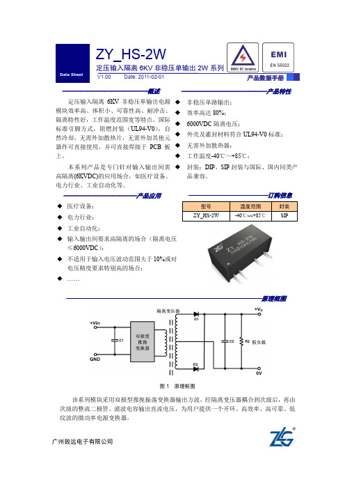
————————————————————————————————原理框图图1 原理框图该系列模块采用双极型推挽振荡变换器输出方波,经隔离变压器耦合到次级后,再由次级的整流二极管、滤波电容输出直流电压,为用户提供一个开环、高效率、高可靠、低纹波的微功率电源变换器。
————————————产品应用◆ 医疗设备; ◆ 电力行业; ◆ 工业自动化;◆ 输入输出间要求高隔离的场合(隔离电压≤6000VDC ); ◆ 不适用于输入电压波动范围大于10%或对电压精度要求特别高的场合; ◆ ……ZY_HS-2W——————————————产品特性◆ 非稳压单路输出; ◆ 效率高达80%; ◆ 6000VDC 隔离电压;◆外壳及灌封材料符合UL94-V0标准; ◆ 无需外加散热器; ◆ 工作温度-40℃~+85℃;◆ 封装:DIP 、SIP 封装与国际、国内同类产品兼容。
——————————————概述定压输入隔离6KV 非稳压单输出电源模块效率高、体积小、可靠性高、耐冲击、隔离特性好,工作温度范围宽等特点。
国际标准引脚方式,阻燃封装(UL94-V0),自然冷却,无需外加散热片,无需外加其他元器件可直接使用,并可直接焊接于PCB 板上。
本系列产品是专门针对输入输出间需高隔离(6KVDC)的应用场合,如医疗设备、电力行业、工业自动化等。
广州致远电子有限公司修订历史销售与服务网络(一)广州周立功单片机发展有限公司地址:广州市天河北路689号光大银行大厦12楼F4邮编:510630电话:(020)38730916 38730917 38730972 38730976 38730977传真:(020)38730925网址:广州专卖店地址:广州市天河区新赛格电子城203-204室电话:(020)87578634 87569917传真:(020)87578842 南京周立功地址:南京市珠江路280号珠江大厦1501室电话:(025) 68123901 68123902传真:(025) 68123900北京周立功地址:北京市海淀区知春路113号银网中心A座1207-1208室(中发电子市场斜对面)电话:(010)62536178 62536179 82628073传真:(010)82614433 重庆周立功地址:重庆市石桥铺科园一路二号大西洋国际大厦(赛格电子市场)1611室电话:(023)68796438 68796439传真:(023)68796439杭州周立功地址:杭州市天目山路217号江南电子大厦502室电话:(0571)89719480 89719481 8971948289719483 89719484 89719485传真:(0571)89719494 成都周立功地址:成都市一环路南二段1号数码科技大厦403室电话:(028)85439836 85437446传真:(028)85437896深圳周立功地址:深圳市深南中路2070号电子科技大厦C座4楼D室电话:(0755)83781788(5线)传真:(0755)83793285 武汉周立功地址:武汉市洪山区广埠屯珞瑜路158号12128室(华中电脑数码市场)电话:(027)87168497 87168297 87168397传真:(027)87163755上海周立功地址:上海市北京东路668号科技京城东座7E室电话:(021)53083452 53083453 53083496传真:(021)53083491 西安办事处地址:西安市长安北路54号太平洋大厦1201室电话:(029)87881296 83063000 87881295传真:(029)87880865销售与服务网络(二)广州致远电子有限公司地址:广州市天河区车陂路黄洲工业区3栋2楼邮编:510660传真:(020)38601859网址:(嵌入式系统事业部)(工控网络事业部)(楼宇自动化事业部)技术支持:CAN-bus:电话:(020)22644381 22644382 22644253 邮箱:****************************iCAN及数据采集:电话:(020)28872344 22644373 邮箱:*********************MiniARM:电话:(020)28872684 28267813邮箱:******************************以太网:电话:(020)22644380 22644385邮箱:*********************************无线通讯:电话:(020) 22644386邮箱:*************************串行通讯:电话:(020)28267800 22644385 邮箱:***********************编程器:电话:(020)22644371邮箱:*************************分析仪器:电话:(020)22644375邮箱:********************ARM嵌入式系统:电话:(020) 22644383 22644384 邮箱:*****************楼宇自动化:电话:(020)22644376 22644389 28267806 邮箱:*************************************************销售:电话:(020)22644249 22644399 22644372 22644261 28872524 28872342 28872349 28872569 28872573 38601786维修:电话:(020)22644245目录1. 电气参数 (1)2. 特征曲线图 (2)2.1隔离特性 (2)2.2温度与输出功率特性曲线 (2)2.3负载与效率曲线 (3)2.4典型误差包络曲线 (4)2.5启动时间 (4)3. 产品列表 (6)3.1SIP封装 (6)4. 典型应用 (7)5. 引脚信息 (8)5.1ZY_HS-2W引脚信息(SIP) (8)6. 机械尺寸、建议印刷板图 (9)6.1机械尺寸 (9)6.2建议印刷板图 (9)6.3包装管尺寸 (10)7. 免责声明 (11)1. 电气参数*表1.1测试环境:室温T=25℃,湿度<80%。
干式隔离变压器安装使用说明书-中英对照

SGC树脂浇注干式隔离变压器SGC Resin Casting Dry Type Isolating Transformer安装使用说明书Installation Manual北京电力设备总厂BEIJING POWER EQUIPMENT GROUP OF P.R.C1 产品概况Product description树脂浇注干式隔离变压器是我公司在引进瑞士TUBOLY.AG、ASTRONIC.AG和意大利BP.2公司的技术、工艺和先进的设备基础上设计、制造而成,产品的技术性能及指标符合GB6450-86、GB/T10228-1997、Q/JT002-1998标准。
该产品具有节能、体积小、重量轻、阻燃、自熄、无污染、不龟裂、抗短路能力强、运行安全性高、耐冲击能力强、损耗低、噪音低、局放低和外形美观等优点。
特别是安装在空间有限、需靠近负荷中心和具有防护要求的场所,更能充分发挥其体积小、阻燃的优越性。
Resin Casting Dry Type Isolating Transformer is designed, manufactured by our company based on the introduced technical and advanced equipment from Swiss TUBOLY.AG, ASTRONIC.AG and Italy BP.2. All technical performance meets standards of GB6450-86, GB/T10228-1997 and Q/JT002-1998. The product has many advantages, such as: energy-saving, small size, light weight, fire retardant, self-extinguishing, pollution-free, and not fragmented, high anti-short circuit capacity, safety operation, high impulse voltage withstand capability and low loss, low noise, low partial discharge and good appearance and so on. When it is installed in limited space, near load center and protection required site, the advantages of small size and fire retardant could be more obvious.2 变压器型号及使用条件Type and working conditions of transformer2.1 产品型号Product typeSGC 1 2 ----- 3 / 4 / 5G: 隔离变压器Isolating TransformerC:环氧树脂浇注固体成型Epoxy resin casting solid moulding1:B------------箔绕foil winding无(vacant)----线绕wire winding2:设计序号Design No.3:额定容量Rated capacity(kVA)4:高压额定电压High rated voltages(kV)5:低压额定电压Low rated voltage(kV)2.2 使用条件Working conditions海拔Altitude above sea level:≤1000m环境温度Ambient temperature:-30~+40℃最高年平均温度The maximum average temperature:+20℃相对湿度Relative humidity:95%(25℃)超出以上正常使用条件时,可与制造厂协商If excess the above normal working conditions, could consult with the manufacturer.电源电压波形:近似于正弦波Supply voltage waveform: close to sinusoidal wave三相电源电压的对称:三相变压器所连接的电源电压应大致对称Three-phase power supply voltage symmetry: power supply voltage connected by three-phase transformer should be symmetry approximately.安装环境:应无明显污秽Installation environment: without obvious pollution地震引发的地面加速度:水平方向:≤3m/S2,垂直方向:≤1.5m/S2Seismic requirement: horizon acceleration at ground level : ≤ 3m/S2, vertically acceleration at ground level: ≤ 1.5m/S2.3. 产品的安装Installation of product3.1 对于无防震要求的场所,变压器可直接放置在地面,安装时应保证变压器外围离开墙体等障碍物或两台变压器之间的距离满足安全要求,变压器有外壳时,距离可适当调整。
AITR系列医用隔离变压器说明书

8000VA 50-60Hz AC230V 36A AC230V/115V 34.7A <12In <200μA 1.04A 235V <6.9V
6300VA 50-60Hz AC230V 28.5A AC230V/115V 27.4A <12In <200μA 0.855A 235V <6.9V
5000VA 50-60Hz AC230V 22.5 AC230V/115V 21.7 <12In <200μA 0.675A 235V <6.9V
1
3 技术参数
型号
绝缘等级 保护等级
功率/电压/电流 额定功率 额定频率 额定输入电压 额定输入电流 额定输出电压 额定输出电流 涌流 泄露电流 空载输入电流 空载输入电压 短路电压 通用参数 熔丝 初级绕组直流电阻 次级绕组直流电阻 铁损 铜损 效率 最高环境温度 空载温升 满负荷温升 噪声等级(空载和满 荷)
AITR 系列医用隔离变压器
1 概述
AITR 系列医用隔离变压器是专门为医疗 IT 系统设计的隔离变压器,为医疗 2 类场所内的重要部件,为 场所内的重要电力负荷提供电力。本产品采用日本进口硅钢片制作铁芯,磁阻小,从而降低损耗,提高效率。 产品初级和次级绕组之间采用加强绝缘,并设屏蔽层。绕组内安装了 PT100 热敏电阻,用于监视绕组温度。 变压器整体进行浸漆处理,以增强抗腐蚀性能。
7 应用范例
7.1 AITR 系列医用隔离变压器在 ICU 室配电中的应用 如图 3 所示。
图 3 AITR 系列医用隔离变压器在 ICU 室配电中的应用
7.2 AITR 系列医用隔离变压器应用接线图
应用接线图如图 4 所示。
AITR8000
Datavideo DAC-80 音频隔离变压器说明书

Instruction Manualw w w.d a t a v i d e o.c o mAUDIO ISOLATIONTRANSFORMER DAC-80Table of ContentsFCC COMPLIANCE STATEMENT (3)WARNINGS AND PRECAUTIONS (3)WARRANTY (5)S TANDARD W ARRANTY (5)T HREE Y EAR W ARRANTY (5)DISPOSAL (6)1.INTRODUCTION (7)F EATURES (7)S YSTEM D IAGRAM (8)2.CONNECTIONS & CONTROLS (9)F RONT P ANEL (9)R EAR P ANEL (10)3.ELECTRONIC CIRCUIT DIAGRAM (11)4.SPECIFICATIONS (11)SERVICE & SUPPORT (12)Disclaimer of Product and ServicesThe information offered in this instruction manual is intended as a guide only. At all times, Datavideo Technologies will try to give correct, complete and suitable information. However, Datavideo Technologies cannot exclude that some information in this manual, from time to time, may not be correct or may be incomplete. This manual may contain typing errors, omissions or incorrect information. Datavideo Technologies always recommend that you double check the information in this document for accuracy before making any purchase decision or using the product. Datavideo Technologies is not responsible for any omissions or errors, or for any subsequent loss or damage caused by using the information contained within this manual. Further advice on the content of this manual or on the product can be obtained by contacting your local Datavideo Office or dealer.FCC Compliance StatementThis device complies with part 15 of the FCC rules. Operation is subject to the following two conditions:(1)This device may not cause harmful interference, and(2)This device must accept any interference received, including interferencethat may cause undesired operation.Warnings and Precautions1.Read all of these warnings and save them for later reference.2.Follow all warnings and instructions marked on this unit.3.Unplug this unit from the wall outlet before cleaning. Do not use liquid oraerosol cleaners. Use a damp cloth for cleaning.4.Do not use this unit in or near water.5.Do not place this unit on an unstable cart, stand, or table. The unit mayfall, causing serious damage.6.Slots and openings on the cabinet top, back, and bottom are provided forventilation. To ensure safe and reliable operation of this unit, and to protect it from overheating, do not block or cover these openings. Do not place this unit on a bed, sofa, rug, or similar surface, as the ventilation openings on the bottom of the cabinet will be blocked. This unit should never be placed near or over a heat register or radiator. This unit should not be placed in a built-in installation unless proper ventilation is provided.7.This product should only be operated from the type of power sourceindicated on the marking label of the AC adapter. If you are not sure of the type of power available, consult your Datavideo dealer or your local power company.8.Do not allow anything to rest on the power cord. Do not locate this unitwhere the power cord will be walked on, rolled over, or otherwise stressed.9.If an extension cord must be used with this unit, make sure that the totalof the ampere ratings on the products plugged into the extension cord do not exceed the extension cord rating.10.Make sure that the total amperes of all the units that are plugged into asingle wall outlet do not exceed 15 amperes.11.Never push objects of any kind into this unit through the cabinetventilation slots, as they may touch dangerous voltage points or short out parts that could result in risk of fire or electric shock. Never spill liquid of any kind onto or into this unit.12.Except as specifically explained elsewhere in this manual, do not attemptto service this product yourself. Opening or removing covers that are marked “Do Not Remove” may expose you to dangerous voltage points or other risks, and will void your warranty. Refer all service issues to qualified service personnel.13.Unplug this product from the wall outlet and refer to qualified servicepersonnel under the following conditions:a.When the power cord is damaged or frayed;b.When liquid has spilled into the unit;c.When the product has been exposed to rain or water;d.When the product does not operate normally under normal operatingconditions. Adjust only those controls that are covered by the operatinginstructions in this manual; improper adjustment of other controls mayresult in damage to the unit and may often require extensive work by aqualified technician to restore the unit to normal operation;e.When the product has been dropped or the cabinet has been damaged;f.When the product exhibits a distinct change in performance, indicatinga need for service.WarrantyStandard Warranty•Datavideo equipment are guaranteed against any manufacturing defects for one year from the date of purchase.•The original purchase invoice or other documentary evidence should be supplied at the time of any request for repair under warranty.•The product warranty period beings on the purchase date. If the purchase date is unknown, the product warranty period begins on the thirtieth day after shipment from a Datavideo office.•Damage caused by accident, misuse, unauthorized repairs, sand, grit or water is not covered under warranty.•Viruses and malware infections on the computer systems are not covered under warranty.•Any errors that are caused by unauthorized third-party software installations, which are not required by our computer systems, are not covered under warranty.•All mail or transportation costs including insurance are at the expense of the owner.•All other claims of any nature are not covered.•Cables and batteries are not covered under warranty.•Warranty only valid in the country or region of purchase.•Your statutory rights are not affected.Three Year Warranty•All Datavideo products purchased after July 1st, 2017 arequalified for a free two years extension to the standardwarranty, providing the product is registered withDatavideo within 30 days of purchase.•Certain parts with limited lifetime expectancy such as LCD panels, DVD drives, Hard Drive, Solid State Drive, SD Card, USB Thumb Drive, Lighting, Camera module, PCIe Card are covered for 1 year.•The three-year warranty must be registered on Datavideo's official website or with your local Datavideo office or one of its authorized distributors within 30 days of purchase.DisposalFor EU Customers only - WEEE MarkingThis symbol on the product indicates that it will not betreated as household waste. It must be handed over tothe applicable take back scheme for the recycling ofWaste Electrical and Electronic Equipment. For moredetailed information about the recycling of this product,please contact your local Datavideo office.CE Marking is the symbol as shown on the left of this page.The letters "CE" are the abbreviation of French phrase"Conformité Européene" which literally means "EuropeanConformity". The term initially used was "EC Mark" and itwas officially replaced by "CE Marking" in the Directive 93/68/EEC in 1993. "CE Marking" is now used in all EU official documents.1. IntroductionDAC-80 is designed to remove hum and buzz created by ground loops. Normal voltage differences in the system grounding points between different pieces of equipment cause small AC power currents to flow in the shield of audio cables. Capacitance between a power transformer’s primary and secondary windings introduce signals to the circuit ground which will also create small current flows in the cable shield. Either of these problems will create hum in audio signals. DAC-80 breaks the inter-equipment ground path and greatly increases the rejection in the input circuits while remaining transparent to the audio signal. Features•Easy to use•Eliminate audio noise caused by ground loops•Designed for low signal loss and low distortion•Passive device (No power required)System Diagram2. Connections & Controls Front PanelCH1 / CH2 Audio InputXLR Balanced Audio input (Channel 1 / 2)LIFT Toggle SwitchThese switches turn to UP position, audio ground not connected. Breaks ground loops, provides audio isolation.These switches turn to DOWN position, for chassis shield and audio ground connected. Corrects balance on audio lines.(Left switch =CH2, Right switch = CH1)Rear PanelCH1 /CH2 Audio OutputXLR Balanced Audio output (Channel 1/ 2).113.Electronic Circuit Diagram4. SpecificationsImpedance600Ω+/- 10%(Input & output)Bandwidth Frequency 20Hz ~20KHz ±0.5dB THD: 1 KHz < 0.015% @ +4dBu; 20Hz: 0.05% @+4dBu Insertion loss <0.5dB Turns Ratio 1:1Input 2 XLR Audio Input Channels Output 2 XLR Audio Output ChannelsDimensions 85mm x 45.2mm x 111.5mm (W x H x D)All the trademarks are the properties of their respective owners. Datavideo Technologies Co., Ltd. All rights reserved 2018Service & SupportJul-07.2017Please visit our website for latest manual /product/DAC-80It is our goal to make your products ownership a satisfying experience. Our supporting staff is available to assist you in setting up and operating your system. Please refer to our web site for answers tocommon questions, support requests or contact your local office below.DATAVIDEO WORLDWIDE OFFICES Tel: +1-562-696 2324Fax:+1-562-698 6930E-mail:*******************E-mail:******************Datavideo Technologies China Co601,Building 10,No.1228,Rd.Jiangchang,Jingan District,Shanghai Tel: +86 21-5603 6599Fax:+86 21-5603 6770E-mail:********************Datavideo Visual Technology(S) Pte Ltd No. 178 Paya Lebar Road #06-07Singapore 409030Tel: +65-6749 6866Fax:+65-6749 3266E-mail:****************************Datavideo Technologies Co. Ltd 10F. No. 176, Jian 1st Rd.,Chung Ho District, New Taipei City 235, Taiwan Tel: +886-2-8227-2888Fax:+886-2-8227-2777E-mail:*********************.tw Datavideo Corporation 7048 Elmer Avenue.Whittier, CA 90602, U.S.A.Datavideo UK LimitedBrookfield House, Brookfield Industrial Estate, Peakdale Road, Glossop, Derbyshire, SK13 6LQ Tel: +44-1457 851 000Fax:+44-1457 850 964E-mail:******************.uk Datavideo Technologies China Co 902, No. 1 business building, Xiangtai Square, No. 129,Yingxiongshan Road, Shizhong District, Jinan City, Shandong Province, China Tel: +86 531-8607 8813E-mail:********************Datavideo France s.a.r.l.Cité Descartes 1, rue Albert Einstein Champs sur Marne 774477 –Marne la Vallée cedex 2Tel: +33-1-60370246Fax:+33-1-60376732E-mail:*****************Datavideo Hong Kong Ltd G/F.,26 Cross Lane Wanchai, Hong KongTel: +852-2833-1981Fax:+852-2833-9916E-mail:******************.hk Datavideo India NoidaFax:+91-0120-2427338E-mail:******************Tel: +91-0120-2427337A-132, Sec-63,Noida-201307, IndiaDatavideo India KochiTel: +91 4844-025336Fax:+91 4844-0476962nd Floor- North Wing, Govardhan Building,Opp. NCC Group Headquaters, Chittoor Road, Cochin- 682035Datavideo Technologies Europe BV Floridadreef 1063565 AM Utrecht,The NetherlandsTel: +31-30-261-96-56Fax:+31-30-261-96-57E-mail:*****************Datavideo Technologies China Co No. 812, Building B, Wankai Center,No.316, Wan Feng Road, Fengtai District, Beijing, ChinaTel: +86 10-8586 9034Fax:+86 10-8586 9074E-mail:********************Datavideo Technologies China CoA1-2318-19 Room,No.8, Aojiang Road,Taijiang District,Fuzhou,Fujian,China Tel**************,*************Fax**************E-mail:********************Datavideo Technologies China Co B-823,Meinian square,No.1388,Middle of Tianfu Avenue,Gaoxin District,Chengdu,SichuanTel: +86 28-8613 7786Fax:+86 28-8513 6486E-mail:********************Datavideo Technologies (S) PTE Ltd No. 178 Paya Lebar Road #06-03Singapore 409030Tel: +65-6749 6866Fax:+65-6749 3266E-mail:******************。
BOD系列环形变压器使用说明书

BOD系列环形变压器使用说明书符合标准: Q/DLX 361□ 安装、使用产品前,请仔细阅读使用11.1BOD系列环形变压器(以下简称变压器),具有性能优良,工作可靠,主要用于家电设备和其它技术要求较高的电子设备中,作为电源变压器和隔离变压器用。
1.2 符合标准:Q/DLX36122.1 海拔不超过2000m。
2.2 环境空气温度:最高温度不超过40℃,最低不低于-5℃。
2.3 空气相对湿度:最湿月的月平均最大相对湿度为90%,同时该月的月平均温度+25℃。
2.4 无剧烈振动和颠簸的地方。
2.5 在无爆炸危险的介质中,且介质中无腐蚀金属和破坏绝缘的气体及导电尘埃的场所。
2.6 不受雨雪侵袭的场所。
2.7 电源电压波形近似于正弦波。
3B O D-□额定容量:VA单相环形变压器44.1 变压器主要技术参数:4.1.1 额定容量:30VA~3000VA4.1.2 额定频率:50Hz/60Hz4.1.3 额定电源电压:220V或其它4.1.4 额定输出电压:12V、24V、36V、220V或其它备注:(1)所列的额定电压和额定输出电压,均为独立输入、输出电压。
(2)除上述以外的电压,由用户与制造厂协商确定。
4.2 变压器绕组型式4.2.1 变压器按其容量、电压的不同分成各种不同的规格,但均为单相多绕组、初次级互耦分开绕制的变压器。
4.2.2 本系列变压器的线圈,当初次级只有一个绕组时,可担负全部额定的容量;若有多个绕组时,则按各绕组应能承担负载的容量分配;但各绕组的容量之和不得超过总容量,见图1、图2、图3、图4。
4.2.3 现举例说明:4.2.3.1 例如图1,BOD-50型容量50VA,输入电压380 V,输出电压36V。
因为初、次级只有一个绕组,所以它可以担负全部容量50VA。
4.2.3.2 例如图2,BOD-200型,容量200VA,输入电压380V,输出电压36V150VA和24V50VA。
因为图中初级只有一个绕组,所以它所承担的容量是额定容量200VA,次级有两个分开的单独绕组,而且各绕组容量已标明,所以它们各自承担容量,但总量之和200VA。
SU5000XFMRT2U 步压隔离变压器说明书

Specifications5kVA / 5kW Step-Down Isolation Transformer 208V to 120V, 2U Rack-Mount, L6-30P, 5-15/20R,L6-30RMODEL NUMBER: SU5000XFMRT2UDescriptionSU5000XFMRT2U step-down isolation transformer converts 208V input from generator, utility or UPS high-voltage source to 120V low-voltage output. 208V 30A input plug with 10-foot (3.1 meters) AC cord connects to L6-30R socket. 12 NEMA 5-15/20R output receptacles accommodate 5-15P or 5-20Pequipment plugs. Built-in L6-30R outlet supports high-voltage output. Supports 2U rack-mount installation with included brackets for 4-post enclosures. Supports 2-post rack-mount installation with optional 2POSTRMKITWM. Supports upright tower installation with 2-9USTAND.FeaturesStep-down/isolation transformer converts high voltage 208V input from generator, utility or UPS to low voltage 120V outputq5kVA/5,000 watt power handling capacity q L6-30P input plugq 10-ft. (3.05 m)/10 gauge input line cordq 12 built-in NEMA 5-15/20R output receptacles accept common 5-15P and 5-20P equipment plugs. Built-in L6-30R outlet supports high voltage output.q4 built-in 20A circuit breakers protect against overload conditionsq Included mounting accessories support 2U installation in 4 post rack enclosures with a max depth requirement of only 20.75 inchesqOptional 2POSTRMKITWM enables 2 post relay-rack installation q Optional 2-9USTAND accessory enables upright tower installationqHighlights5kVA / 5,000 watt step-down isolation transformer converts 208V to 120VqSimple plug-in installation with L6-30P input plug, 10-ft. (3.05m) cordq12 NEMA 5-15/20R 120VAC outlets accommodate 5-15P and 5-20P equipment plugs, L6-30R outlet accommodates one high voltage plugqIdeal means of converting UPS,utility, generator or other 208V input to 120VAC qSupports 2U rackmount installationqPackage IncludesSU5000XFMRT2U step-down,isolation transformerq4 post rackmount accessories q Owner's manual with warranty informationq© 2023 Eaton. All Rights Reserved. Eaton is a registered trademark. All other trademarks are the property of their respective owners.。
- 1、下载文档前请自行甄别文档内容的完整性,平台不提供额外的编辑、内容补充、找答案等附加服务。
- 2、"仅部分预览"的文档,不可在线预览部分如存在完整性等问题,可反馈申请退款(可完整预览的文档不适用该条件!)。
- 3、如文档侵犯您的权益,请联系客服反馈,我们会尽快为您处理(人工客服工作时间:9:00-18:30)。
隔离变压器
使用说明书
一、概述:
隔离变压器系根据国家标准《GB6450-86》、《GB9554-87》及《BJ297-78》设计制造。
二、用途:
本产品作为负载与电力网隔离设备及升降压,广泛应用于发电厂、电力系统、工矿、交通企业的负荷与电力网需电气隔离的场所作电源用,是自动控制系统、通讯调度网络、计算机设备、精密测量试验系统的净化(抗干扰)之必备设备。
三、特点:
1、SG系列隔离变压器采用优质冷轧硅钢片、高强度绝缘漆包线和SBECB双玻璃丝包线及E、H级绝缘材料制造,防护式产品按TP2X 级的要求设计外壳。
2、本产品分无屏蔽的单、双屏蔽三种,除前者防止一、二次电压互窜外,还可抑制一次侧的杂波对二次侧的影响。
3、该产品为干式防护式外壳,体积小、重量轻、安装使用方便、适用于固定、移动的场合。
四、使用条件:
1、海拔高度不超过1000米。
2、环境温度不超过45℃,相对湿度不大于85%。
3、使用场地应无水蒸汽、腐蚀气体及易燃易爆炸性介质。