Goodwin Cryogenic brochure 低温阀门
低温阀门结构

低温阀门结构
低温阀门结构是一种特殊设计的阀门,用于在低温工作环境中进行流体控制。
低温阀门主要应用于液化天然气(LNG)、液氮、液氧等冷冻介质的输送系统中,确保流体在极低温下的安全运输和流动。
低温阀门结构的设计考虑了以下几个主要因素:
1. 密封性能:由于低温工况下介质的特殊性质,阀门的密封性能要求更高。
因此,低温阀门通常采用双密封结构,例如双密封蝶阀或双密封球阀。
这种结构能够有效防止介质泄漏,确保系统的安全性。
2. 材料选择:在低温环境下,常规金属材料的性能可能会受到影响,导致强度下降。
因此,低温阀门通常采用特殊的材料,如不锈钢、镍合金、钛合金等,以确保阀门在低温下的稳定性和可靠性。
3. 保温措施:为了防止低温介质对阀门结构的冷冻和冻结,低温阀门通常采用保温措施。
例如,在阀门外壳上加装保温材料,或者在阀门内部设置保温套管,以减少热量的散失。
4. 冷却措施:在某些特殊情况下,低温阀门还需要冷却措施,以防止阀门过热。
例如,在阀门周围设置冷却装置,通过循环冷却介质来保持阀门的温度在正常范围内。
总的来说,低温阀门结构的设计旨在确保阀门在极端低温环境下的正常运行,并保证系统的安全性和可靠性。
随着液化天然气和其他低温介质的应用不断扩大,低温阀门的需求也在不断增加,因此对于低温阀门结构的研发和创新也变得越来越重要。
低温球阀标准
低温球阀标准一、材料和结构1.低温球阀应由符合设计要求的材料制成,如不锈钢、碳钢等。
具体材料应符合相应的标准要求。
2.低温球阀的结构应合理,易于拆卸和安装,便于维护和修理。
阀门内部结构应保持紧凑,尽量减少死角,便于清洗和无损检测。
二、尺寸和公差1.低温球阀的尺寸应符合设计要求,包括球体直径、阀座直径、连接尺寸等。
2.公差应符合相关标准要求,以确保阀门的密封性能和使用性能。
三、试验方法和检验规则1.低温球阀应按照相关标准进行压力试验、密封试验、动作试验等。
试验方法应符合相关标准要求。
2.检验规则应包括外观质量、尺寸精度、密封性能等方面的检验内容和方法。
检验规则应符合相关标准要求。
四、性能要求1.低温球阀应具有良好的密封性能,在低温条件下能够保持良好的密封效果。
2.低温球阀的动作应灵活可靠,操作方便,能够适应相应的介质和温度条件。
3.低温球阀应具有较强的耐腐蚀性能,能够适应各种腐蚀介质的环境。
4.低温球阀应具有较高的耐低温性能,能够在低温条件下正常工作。
五、外观质量1.低温球阀的外观应平整光滑,无明显的缺陷和损伤。
2.零件的加工和装配应符合设计要求,各部分配合良好,无明显松动和磨损。
六、涂装和防护1.低温球阀应进行涂装处理,以保护阀门表面不受腐蚀和损伤。
涂装材料应符合相关标准要求。
2.在使用过程中,阀门应按照规定进行维护和保养,保持其良好的使用状态。
七、标志、包装、运输、贮存1.低温球阀应有清晰的标志,包括产品名称、型号、规格、生产日期等。
标志应符合相关标准要求。
2.包装应符合产品防护要求,以防止阀门在运输过程中受到损伤。
包装材料应符合相关标准要求。
3.运输过程中,应注意保护阀门,避免其受到机械损伤和气候影响。
4.贮存场所应干燥、通风良好,避免阀门受潮和变质。
贮存时间不宜过长,如超过一年应重新进行检验和试验。
低温阀门关键性能国内外标准技术差异分析

标准比对低温阀门关键性能国内外标准技术差异分析■ 吴超俊1 缪克在1* 胡志涛1 方 威2 张 帆1(1. 浙江省泵阀产品质量检验中心;2. 苏州西玛流体科技有限公司)摘 要:为了研究低温阀门关键性能与结构,本文对比了GB/T 24925—2019、BS 6364-1984(R1998)、ISO 28921-1:2022、MSS SP-134-2012等国内外标准在适用范围、主要技术指标、测试方法的区别以及由此产生的影响。
综述了低温阀门的应用工况、典型产品分类、典型壳体材料、典型结构特征以及国内外常用标准分类等,指出了低温阀门的温度范围、伸长颈部结构设计特征以及需进行低温性能试验的温度临界点等。
阐述了国标GB/T 24925—2019规定的低温试验过程未区分硬密封与软密封阀座泄漏率以及阀座泄漏率测量的局限性,通过理论分析验证说明了阀座泄漏率准确测量与换算方法,为低温阀门性能提升以及国标的完善与修订提供技术指引。
关键词:低温阀门,关键性能,低温性能试验,阀座泄漏率DOI编码:10.3969/j.issn.1002-5944.2024.09.028Analysis of Technical Differences between Domestic and Foreign Standards for Key Performance of Cryogenic ValvesWU Chao-jun1 MIAO Ke-zai1* HU Zhi-tao1 FANG Wei2 ZHANG Fan1(1. Zhejiang Inspection Center of Pump and Valve Product Quality; 2. Suzhou SEARCHST Co., Ltd.)Abstract:In order to study key performance and structure of cryogenic valves, the paper compares the differences in application scope, main technical indexes, test methods and influence of domestic and foreign standards such as GB/T 24925-2019, BS 6634-1984 (R1998), ISO 28921-1:2022, and MSS SP-134-2012. The application conditions, typical product classification, typical valve shell materials, typical structure characteristics and common standards classification at home and abroad for cryogenic valves are summarized. The temperature range of cryogenic valves, the structural design features of extended neck and the temperature critical point for cryogenic performance test are pointed out. The low temperature test process stipulated in GB/T 24925-2019 does not distinguish between hard seals and soft seals in terms of the leakage rate of valve seats, and the measurement of leakage rate of valve seats, which is expounded as shortcomings. The paper explains the accurate measurement method and conversion method of valve seat leakage rate through theoretical analysis and verification, which provides technical guidance for the improvement of cryogenic valve performance as well as the development and revision of national standards.Keywords: cryogenic valve, key performance, cryogenic performance test, valve seat leakage rate0 引 言低温阀门广泛应用于LNG、LO2、LN2、乙烯、丙烯等低温制冷工况领域,起到流通、截断、调节等关键作用,其典型结构特征为具有伸长颈部阀盖、部分带有隔离滴盘等结构。
低温阀门标准

低温阀门标准
1.JB/T10281低温阀门通用技术条件
1.1设计压力PN:-0.20~+0.05MPa;1.2温度:-
40~+180℃。
2.设计温度、压力级别、密封材料、驱动方式
2.1设计温度:PN≤-40℃;2.2压力级别:
PN1.0~10.0MPa;2.3密封材料:丁腈橡胶或氟橡胶;2.4驱动方式:手动、电动、气动、液动。
3.低温阀门标准主要技术条件及说明
3.1低温阀门的适用范围(指在所规定的温度和压力条件下,密封面不发生变形或失效,并具有良好的密封性能。
)
在低温下工作的阀门称为低温阀门。
低温阀门中主要适用于低温介质(如液氮)或含有少量水分、气体的低温介质,它要求介质的温度低于-60℃或低于-20℃以下。
当介质温度低于-60℃时,一般采用石墨阀座(或橡胶阀座)和金属阀座(或非金属阀座);当介质温度低于-20℃时,一般采用石墨阀座和金属阀座;当介质温度高于-40℃时,一般采用金属阀座和非金属阀座。
—— 1 —1 —。
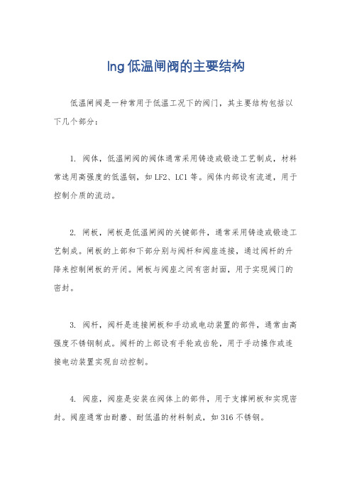
lng低温闸阀的主要结构
lng低温闸阀的主要结构
低温闸阀是一种常用于低温工况下的阀门,其主要结构包括以下几个部分:
1. 阀体,低温闸阀的阀体通常采用铸造或锻造工艺制成,材料常选用高强度的低温钢,如LF2、LC1等。
阀体内部设有流道,用于控制介质的流动。
2. 闸板,闸板是低温闸阀的关键部件,通常采用铸造或锻造工艺制成。
闸板的上部和下部分别与阀杆和阀座连接,通过阀杆的升降来控制闸板的开闭。
闸板与阀座之间有密封面,用于实现阀门的密封。
3. 阀杆,阀杆是连接闸板和手动或电动装置的部件,通常由高强度不锈钢制成。
阀杆的上部设有手轮或齿轮,用于手动操作或连接电动装置实现自动控制。
4. 阀座,阀座是安装在阀体上的部件,用于支撑闸板和实现密封。
阀座通常由耐磨、耐低温的材料制成,如316不锈钢。
5. 密封装置,低温闸阀的密封装置主要包括阀座密封和闸板密封。
阀座密封通常采用金属密封或弹性密封结构,能够在低温下保
持良好的密封性能。
闸板密封通常采用填料密封或金属密封,以确
保阀门在工作过程中的密封性能。
6. 操作装置,低温闸阀可以通过手动操作或电动操作来实现开
闭控制。
手动操作通常采用手轮或齿轮装置,电动操作则通过电动
装置实现远程控制。
综上所述,低温闸阀的主要结构包括阀体、闸板、阀杆、阀座、密封装置和操作装置。
这些结构的设计和选择都需要考虑低温工况
下的特殊要求,以确保阀门在低温环境中的安全可靠运行。
低温阀门 基础知识
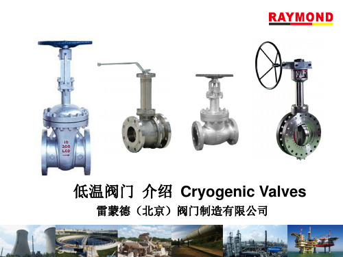
温度℃ 公称通径 mm 15 20 25 40 50 80 100 in ½ ¾ 1 1½ 2 3 4Biblioteka ≥-60≥-100
<-100
颈部长度L/mm
90 100 100 110 110 120 130 110 110 120 130 130 150 160 130 140 150 160 170 190 200
4、阀座、阀瓣(闸板)密封面 低温阀门的关闭件采用钴铬钨 硬质合金堆焊结构。软密封结 构由于聚四氟乙烯膨胀系数大, 低温变脆,所以仅适用于温度 高于-70℃的低温阀。聚三氟乙 烯可用于-162℃的低温阀。 6、阀杆 阀杆材料采用奥氏体不锈钢。
8、填料函及填料 填料函不能与低温直接接触,而设计在长颈阀 盖顶端,使填料函处于离低温较远的位置,在 0℃以上的温度环境下工作。这样,提高了填料 函的密封效果。在泄漏时,或当低温流体直接接 触填料造成密封效果下降时,可以从填料函中间 加入润滑脂形成油封层,降低填料函的压差,作 为辅助密封措施。填料函多采用带有中间金属隔 环的二段填料结构。但也有的采用一般阀门填料 函结构和阀杆能自紧的二重填料函结构等其他型 式。 9、保冷 又称滴水板,是一块焊在填料函下部长颈部 分的圆形板。其主要作用:防止环境中的水 气遇冷成水之后,直接流入保温层里,结冰。
低温阀门 介绍 Cryogenic Valves
雷蒙德(北京)阀门制造有限公司
低温阀是一种在低温介质中工作的阀门。随着现代科技的发展,低温 工程制品的生产规模不断扩大,液氧、液氮以及液化石油气等得到广泛的 应用。尤其是液化天然气越来越受到世界各国的重视。 液化氨的温度-269℃,液氢的温度-254 ℃,液化氦的温度-196 ℃,液 氧的温度-183 ℃,液化天然气的温度-162 ℃,以上物质的液化分馏,运输 和储存都需要使用大量的低温阀门。 低温阀门的用途越来越广,需求越来越大,对低温阀的技术性能和工作 特性的要求也在不断提高。我国低温阀的研究起步较晚,品种规格少。过 去,国内引进装置上的低温阀主要依赖进口,为了改变这种状况,我公司 在国内进行开发并试制,经用户使用反映良好,完全能替代进口。 经过我公司多年制造,已积累了丰富的经验,从设计、工艺到制造日 趋成熟,并已开发形成了低温阀门的系列产品。 主要用于乙烯,液化天然气装置,天然气LPG、 LNG储罐,接受基地 及卫星站,空分设备,石油化工尾气分离设备,液氧、液氮、液氩、二氧 化碳低温贮槽及槽车、变压吸附制氧等装置上。 输出的液态低温介质如乙烯、液氧、液氢、液化天然气、液化石油产品 等,不但易燃易爆,而且在升温时要气化,气化时,体积膨胀数百倍。
低温阀门的设计与安装要求
低温阀门的设计与安装要求随着低温工程的广泛应用,低温阀门的使用越来越普遍。
低温阀门是一种特殊的阀门,其材料、结构、制造、安装等方面都需要特别注意。
本文将从设计和安装两个方面来介绍低温阀门的要求。
低温阀门的设计要求材料选用低温阀门材料的选用非常重要。
低温下,阀门部件容易出现脆裂现象,因此材料的韧性、强度、耐腐蚀性能都需要特别注意。
常用的材料包括不锈钢、钼合金、钛合金等。
结构设计低温阀门的结构设计也需要考虑其在低温下的特殊环境。
首先,应采用低温材料,同时,要保证阀门操作流畅,不易卡死;其次,需要考虑隔热绝热措施,避免阀门部件结冰;最后,应设计耐低温的密封结构,确保阀门的密封性。
制造工艺制造工艺是保证低温阀门质量的关键。
低温阀门制造要保证工艺的可靠性和稳定性,尤其需要注意材料的冷处理和焊缝质量。
同时,制造工艺要考虑低温条件下的热影响和材料变形问题。
低温阀门的安装要求环境温度在低温环境下,阀门的安装位置和温度也需要特别关注。
安装位置一定要考虑加热措施,尤其是在极端寒冷的环境中。
温度方面,需要确保低温阀门在安装过程中不受到温度差的影响,以免阀门部件出现变形而造成密封不良。
接口连接低温阀门的接口连接也需要特别注意。
接口密封性和连接强度是阀门使用过程中不可或缺的要素。
在低温条件下,尤其需要确保接口铰链的质量和合理性。
峰值压力低温阀门还需要考虑峰值压力问题。
在使用过程中,如果阀门遭受过大的压力,就容易出现破裂等问题。
因此,在低温阀门的使用过程中,要特别注意峰值压力的问题,确保阀门的安全稳定运行。
结论低温阀门在设计和安装过程中,需要特别关注材料、结构、制造工艺、接口连接等方面的问题。
只有将这些要素全面考虑,才能保证低温阀门的使用效果和安全性。
低温不锈钢阀门的适用温度

低温不锈钢阀门的适用温度1. 介绍低温不锈钢阀门是一种特殊材料制成的阀门,适用于低温工况下的流体控制。
本文将对低温不锈钢阀门的适用温度进行全面、详细、完整且深入地探讨。
2. 低温不锈钢阀门的特点低温不锈钢阀门具有以下特点: - 良好的低温性能:低温不锈钢材料具有良好的低温韧性和抗冷脆性能,能够在极低温度下正常工作。
- 耐腐蚀性:不锈钢材料具有优异的耐腐蚀性能,能够在腐蚀性介质中长期稳定运行。
- 密封性能好:低温不锈钢阀门采用优质密封材料,能够有效防止介质泄漏。
- 结构简单可靠:低温不锈钢阀门的结构简单、可靠,易于维修和维护。
3. 低温不锈钢阀门的适用温度范围低温不锈钢阀门的适用温度范围受多种因素影响,包括材料选择、阀门结构、介质性质等。
一般来说,低温不锈钢阀门的适用温度范围为-196℃至-40℃。
3.1 低温不锈钢材料选择低温不锈钢阀门的材料选择是影响适用温度范围的关键因素之一。
常用的低温不锈钢材料有316L、304L、321等。
这些材料具有良好的低温性能和耐腐蚀性能,能够在低温环境下安全可靠地工作。
3.2 阀门结构设计低温不锈钢阀门的结构设计也对适用温度范围有一定影响。
合理的结构设计能够提高阀门的密封性能和耐低温性能。
例如,采用双金属密封结构可以有效解决低温下的泄漏问题。
3.3 介质性质介质的性质对低温不锈钢阀门的适用温度范围同样具有重要影响。
不同的介质具有不同的低温要求,因此需要根据介质的特点选择合适的低温不锈钢阀门。
4. 低温不锈钢阀门的应用领域低温不锈钢阀门广泛应用于以下领域: - 液化天然气(LNG)工业:低温不锈钢阀门在液化天然气工业中扮演着重要的角色,用于控制液化天然气的流动和压力。
- 化工工业:低温不锈钢阀门在化工工业中被广泛应用,用于控制各种腐蚀性介质的流动。
- 医药工业:低温不锈钢阀门在医药工业中用于控制低温介质的流动,确保生产过程的安全和稳定。
5. 低温不锈钢阀门的维护与保养为了确保低温不锈钢阀门的正常工作和延长使用寿命,需要进行定期维护和保养。
美标低温阀门 技术条件

美标低温阀门技术条件嘿,咱今儿就来聊聊美标低温阀门这档子事儿哈!你说这美标低温阀门,那可真是个神奇的玩意儿。
就好像是在极端寒冷环境下坚守岗位的小战士,得有一身过硬的本领才行嘞!先来说说这技术条件里的材料要求吧。
那可得精挑细选,得是能抗得住低温的家伙什儿。
这就好比是给小战士选一身坚固又保暖的铠甲,要是材料不行,到了冷得要命的时候,咔,裂了或者坏了,那可就糟糕透顶啦!所以啊,这材料得足够坚韧,足够耐得住低温的折腾。
然后呢,是设计方面。
这设计可不能马虎,就像给小战士设计战斗策略一样。
得考虑到各种情况,怎么让流体顺畅通过,怎么保证密封性能良好,这些都得细细琢磨。
要是设计不好,那不是这儿漏一点,就是那儿出点毛病,那还怎么干活呀!制造工艺也是重中之重啊!就好比是打造一把绝世好剑,每一个步骤都得精益求精。
从零部件的加工到整体的组装,都得严丝合缝,不能有半点马虎。
不然到时候用起来问题百出,那可就麻烦大啦!再看看这性能要求,那得像要求运动员一样,高标准严要求。
开关要灵活吧,不能卡顿;密封要可靠吧,不能随便就漏了。
这就跟人跑步一样,得跑得快,还得姿势标准,不能出岔子。
还有啊,这低温阀门还得经过各种严格的测试。
这就像是给小战士进行魔鬼训练一样,只有通过了这些测试,才能证明自己是真正的强者。
压力测试、密封测试等等,一个都不能少。
你想想,要是在一些关键的地方,比如石油化工行业,或者一些低温环境的工程里,这美标低温阀门要是不靠谱,那得带来多大的麻烦呀!那损失可就大了去啦!所以啊,对于这美标低温阀门的技术条件,咱可千万不能轻视。
总之呢,美标低温阀门的技术条件那是相当重要啊!这可关系到好多方面呢,它得可靠,得耐用,得能在低温环境下发挥出色。
咱可得重视起来,让这些小战士在寒冷的战场上英勇作战,为我们的生活和工作保驾护航!可别小瞧了它们哟!。
低温阀门的用途

低温阀门是一种特殊的阀门,用于在低温环境下控制流体流动。
以下是一些低温阀门的用途:
1.液化天然气(LNG)领域:在液化天然气领域,低温阀门用于调节液相和气
相的流动,保持系统的压力和温度稳定。
低温球阀、低温截止阀、低温节流阀等是液化天然气领域常用的低温阀门。
2.航天领域:在航天领域,低温阀门用于控制推进剂的流动和调节发动机的推
力。
由于推进剂在低温下容易凝固,因此需要使用低温阀门来确保其顺畅流动。
3.核能领域:在核能领域,低温阀门用于控制核反应堆中液态钠或其他冷却剂
的流动,保持反应堆的温度和压力稳定。
4.冶金和化工领域:在冶金和化工领域,低温阀门用于控制各种化学物质的流
动和反应过程。
例如,在制氢、制氮等化学工艺中,低温阀门可以确保反应物在低温下顺畅流动。
除了以上领域,低温阀门还广泛应用于其他需要控制流体流动的领域,如制冷、空分、医药、食品等领域。
在这些领域中,低温阀门的作用是调节流体的流量、压力和温度,保持系统的稳定和安全运行。
美标低温截止阀
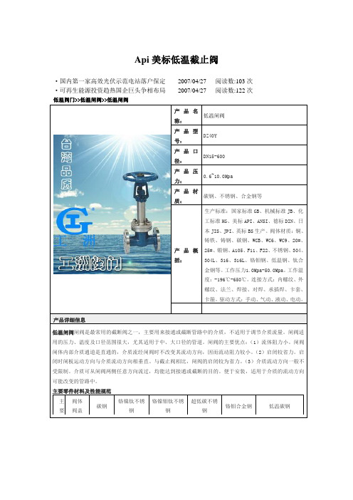
Api美标低温截止阀·国内第一家高效光伏示范电站落户保定2007/04/27 阅读数:103次·可再生能源投资趋热国企巨头争相布局2007/04/27 阅读数:122次低温阀门>>低温闸阀>>低温闸阀产品名称:低温闸阀产品型号:DZ40Y产品口径:DN15-600产品压力:0.6~10.0Mpa产品材质:碳钢、不锈钢、合金钢等产品概括:生产标准:国家标准GB、机械标准JB、化工标准HG、美标API、ANSI、德标DIN、日本JIS、JPI、英标BS生产。
阀体材质:铜、铸铁、铸钢、碳钢、WCB、WC6、WC9、20#、25#、锻钢、A105、F11、F22、不锈钢、304、304L、316、316L、铬钼钢、低温钢、钛合金钢等。
工作压力1.0Mpa-50.0Mpa。
工作温度:-196℃-650℃。
连接方式:内螺纹、外螺纹、法兰、焊接、对焊、承插焊、卡套、卡箍。
驱动方式:手动、气动、液动、电动。
产品详细信息低温闸阀闸阀是最常用的截断阀之一,主要用来接通或截断管路中的介质,不适用于调节介质流量。
闸阀适用的压力、温度及口径范围很大,尤其适用于中、大口径的管道。
闸阀的主要优点:(1)流体阻力小。
闸阀闸体内部介质通道是直通的,介质流经闸阀时不改变其流动方向,因而流动阻力较小。
(2)启闭较省力。
启闭时闸板运动方向与介质流动方向相垂直。
与截止阀相比,闸阀的启闭较为省力。
(3)介质流动方向一般不受限制。
介质可从闸阀两侧任意方向流过,均能达到接通或截断的目的。
便于安装,适用于介质的流动方向可能改变的管路中。
主要零件材料及性能规范主要阀体阀盖碳钢铬镍钛不锈钢铬镍钼钛不锈钢超低碳不锈钢铬钼合金钢低温碳钢"1" " 41 180 133 497 " " "SFD 196Z-40C600P11/2" 600 57 180 152 560 OCr 18Ni 9 ≥-196 液氨、乙烯、液化天然气等 " 2" " 165 250 292 640 " " " " 3" " 210 300 356 860 " " " "4""273350 4321010 """"6" " 356 510 559 1320" " "低温阀门>>低温止回阀>>低温止回阀20 0 8 66441934927636.412-3238125 0 10 79151432324716.416-3545730 0 12 842559489381746.420-35584低温阀门>>低温球阀>>锻钢低温焊接球阀产品名称:锻钢低温焊接球阀产品型号:DQ61Y产品口径:DN15-50产品压力:0.6~32.0Mpa产品材质:铸钢、不锈钢、合金钢等产品概括:生产标准:国家标准GB、机械标准JB、化工标准HG、美标API、ANSI、德标DIN、日本JIS、JPI、英标BS生产。
WEKA Cryogenic Components紧凑型低温阀门说明书
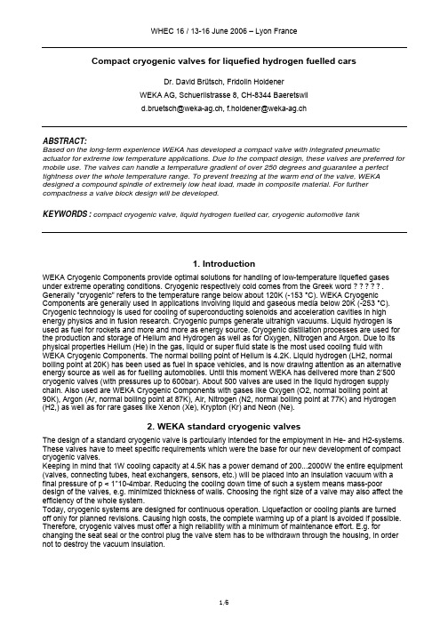
Compact cryogenic valves for liquefied hydrogen fuelled carsDr. David Brütsch, Fridolin HoldenerWEKA AG, Schuerlistrasse 8, CH-8344 BaeretswilABSTRACT:Based on the long-term experience WEKA has developed a compact valve with integrated pneumatic actuator for extreme low temperature applications. Due to the compact design, these valves are preferred for mobile use. The valves can handle a temperature gradient of over 250 degrees and guarantee a perfect tightness over the whole temperature range. To prevent freezing at the warm end of the valve, WEKA designed a compound spindle of extremely low heat load, made in composite material. For further compactness a valve block design will be developed.KEYWORDS: compact cryogenic valve, liquid hydrogen fuelled car, cryogenic automotive tank1. IntroductionWEKA Cryogenic Components provide optimal solutions for handling of low-temperature liquefied gases under extreme operating conditions. Cryogenic respectively cold comes from the Greek word ?????. Generally "cryogenic" refers to the temperature range below about 120K (-153 °C). WEKA Cryogenic Components are generally used in applications involving liquid and gaseous media below 20K (-253 °C). Cryogenic technology is used for cooling of superconducting solenoids and acceleration cavities in high energy physics and in fusion research. Cryogenic pumps generate ultrahigh vacuums. Liquid hydrogen is used as fuel for rockets and more and more as energy source. Cryogenic distillation processes are used for the production and storage of Helium and Hydrogen as well as for Oxygen, Nitrogen and Argon. Due to its physical properties Helium (He) in the gas, liquid or super fluid state is the most used cooling fluid with WEKA Cryogenic Components. The normal boiling point of Helium is 4.2K. Liquid hydrogen (LH2, normal boiling point at 20K) has been used as fuel in space vehicles, and is now drawing attention as an alternative energy source as well as for fuelling automobiles. Until this moment WEKA has delivered more than 2’500 cryogenic valves (with pressures up to 600bar). About 500 valves are used in the liquid hydrogen supply chain. Also used are WEKA Cryogenic Components with gases like Oxygen (O2, normal boiling point at90K), Argon (Ar, normal boiling point at 87K), Air, Nitrogen (N2, normal boiling point at 77K) and Hydrogen (H2,) as well as for rare gases like Xenon (Xe), Krypton (Kr) and Neon (Ne).2. WEKA standard cryogenic valvesThe design of a standard cryogenic valve is particularly intended for the employment in He- and H2-systems. These valves have to meet specific requirements which were the base for our new development of compact cryogenic valves.Keeping in mind that 1W cooling capacity at 4.5K has a power demand of 200...2000W the entire equipment (valves, connecting tubes, heat exchangers, sensors, etc.) will be placed into an insulation vacuum with a final pressure of p < 1*10-4mbar. Reducing the cooling down time of such a system means mass-poor design of the valves, e.g. minimized thickness of walls. Choosing the right size of a valve may also affect the efficiency of the whole system.Today, cryogenic systems are designed for continuous operation. Liquefaction or cooling plants are turned off only for planned revisions. Causing high costs, the complete warming up of a plant is avoided if possible. Therefore, cryogenic valves must offer a high reliability with a minimum of maintenance effort. E.g. for changing the seat seal or the control plug the valve stem has to be withdrawn through the housing, in order not to destroy the vacuum insulation.Frequently applied dimensions are from DN2 to DN200 where “DN” means diameter nominal and the number indicates the diameter of the valve bore in "mm". Primarily the size of the valve bore and valve travel determines the flow characteristic of the valve. A second important factor is the size and the design of the volume after the valve bore (outlet side). Reducing the flow resistance in a valve means minimal pressure drop. This can be achieved by a design with sufficient space after the bore for pressure increase. While selecting or purchasing cryogenic valves same nominal diameters from different suppliers are compared. The very central aspect is to compare the real valve bore and the associated Kv value (Cv = 1.16 * Kv). This will give you the best idea of the efficiency of a valve. WEKA standard cryogenic valves have a leading position in aspect of valve efficiency.So far normal operating pressures for cryogenic valves are from vacuum up to 25bar or 40bar. Beside these standard applications, WEKA has delivered also bellows sealed control valves for up to 630bar. In the future higher pressure valves will draw more attention because they enable smaller and more efficient plants and applications. Generally WEKA Cryogenic Valves are available asa) Bellows sealed valves followed by a security back-up sealing and a plugged leak test port. This high quality sealing system guarantees the highest tightness and safety under pressure and vacuum conditions. Preferably it will be used for low density fluids like He or H2. For high purity gases it is also recommended to use bellows sealed valves.b) Packing sealed valves with an elastomeric quad-ring for applications which have reduced requirements regarding tightness e.g. for fluids like Nitrogen (N2), Air, etc. However these valves could also be used for low density gases. Static seal to outside between valve body and bonnet and inset respectively is made with an elastomeric o-ring joint at the warm top end of the valve.The valve body is completely welded and manufactured from stainless steel (tubes and forged bars). Therefore the valves have a high operational reliability in continuous service and offer high protection against losing the insulation vacuum. Different applications require different body patterns. Standard for cryogenic cold boxes is the angle pattern (E-pattern). In transfer lines or pipes the globe or straight pattern is often used (see D-pattern or Z-pattern). On special request the Y-pattern is also available.E-Pattern D-pattern Z-pattern Y-patternFigure 1: Different body patternThe cryogenic length of a valve depends on the nominal diameter, the operating temperature and the space available in the installation. Standard cryogenic length’s are h = 600, 875, 1000 or 1300mm. If needed, other dimensions will be manufactured between the minimum (h = 300mm) up to max. 2000mm. Up to 1000mm the standard design is used. Considering the thermal expansion, valves with a cryogenic length longer than 1000mm need special compensating elements.The wall thickness of body and inset is optimized regarding minimal heat load by thermal conductivity and pressure and shut-off loads. For further reduction of heat loads, a thermal contact could be brazed to body pipe to contact a cooling shield.The valve seat is integrally machined into the valve body at the cold bottom end. It will be closed by a polymeric soft seal. The cardanic stem inset design guarantee seat tightness over the full temperature range. Some movement by thermal contraction of the piping could be compensated. Seal heads of valves size >= DN20 are spherical flexible joined to the inset. Smaller valves have elastically buckling spindle tubes. The seat tightness and flow control characteristic are separated by the design and adaptable to different specifications required.Figure 2: Flexible seal headGuiding elements in the warm and cold part of the valve are usually made from Aluminium-Bronze. Not by cold medium contacted areas could also consist of brass alloys. Best results regarding seat tightness and temperature stability will show thermoplastics like PTFE, PCTFE or PE UHMW. Also PEEK is very suitable in specific conditions. Designing the valve seat means also consider the special characteristics of theseplastics at ambient and cryogenic temperatures. Normally used for the O-ring seals are the elastomers NBR or FPM.Exact tolerances of the valve bore made it possible to use for both, on/off- (digital-) and control applications. For control valves appropriate standard flow plugs with either equal- % (1:100) or linear flow characteristics are available. Plugs with other special flow characteristics will be calculated and produced on request. Digitalvalves will be equipped with a flow trim which assures highest possible Kv value.0102030405060708090100relative valve travel (%)r e l a t i v e v a l v e f l o w c o e f f i c i e n t k v (%)Figure 3: Different flow characteristicsStandard cryogenic valves are equipped with a vacuum weld-in flange for cold-box mounting from the bottom side. On request we deliver valves without weld-in flange or valves with bigger flange diameter forassembling through the top plate. In special cases valves with vacuum jacket or with special vacuum flange assembly could be designed and manufactured.2.1 Valve ActuatorsWEKA Cryogenic Valves are normally equipped with pneumatic diaphragm actuators. Selectable are also manual drives or electric actuators. Actuator control accessories like limit switches, positioner, 3/2-way solenoid valves etc. could be selected according the specified valve function (control or on/off valve).with positioner with inductive sensors electric actuator manual driveFigure 4: Actuator typesThe actuator size and type is derived by the nominal valve size (DN), the specified operating or shut off pressure, the available energy (air pressure, power supply) and the plant control system. Particularly to consider are also the specifications about actuating time, fail function in case of energy loss and other restrictions like x-ray radiation or explosion proofed equipment.Due to large spatial expansion of cryogenic systems the newest developments of the field bus technology have an improved relevance for the process control. Communicating with the field devices the will be more and more important, e.g. WEKA valves are available with profibus or foundation fieldbus interface. This opens new perspectives for the operation and maintenance of a plant. Valves equipped with a digital electro-pneumatic position controller may receive over the field bus new operating parameters. On the other hand, number of valve movements, travel and actuating time could be logged. Deviations or special alarm limits could be processed by the master control.3. Compact cryogenic valves for LH2 fuelled carsThree years ago, an automotive OEM asked for compact valves with on/off function. Based on the long-term experience WEKA has developed a special valve with integrated pneumatic actuator for liquid hydrogen (LH2) application. The valves are built in a LH2 tank, where every tank needs two or three valves. The following figure shows the basic elements of such a tank. Two containers are separated by an insulation vacuum and super insulation carried by two suspensions. The pressure in the tank is controlled by an electrical heater and a relief valve. Extracting hydrogen normally happens in gaseous state; whileaccelerating or in other power consuming situations hydrogen will be extracted in liquid form.heat exchangerShieldOuter vessel(Shut off valves)Figure 5: Automotive tank for LH2Due to limited space the valves had to be very short. The actual valve design has an overall length of 300mm. Resulting fact is, that the valve has to handle a temperature gradient of over 200 degrees over a cryogenic length of 130mm. To prevent freezing at the warm end of the valve, WEKA designed a compound spindle of extremely low heat load, made in composite material.Furthermore reducing the evaporation rate is a goal of all tank manufacturers. Therefore the valve has to guarantee a perfect tightness over the whole temperature range. On one hand the valve is bellows sealed,on the other hand the soft-sealing head has a parabolic geometry.Pneumaticpiston actuatorSpring loaded cap(safety position)Weld-in flange forvaccuum insulationMinimized cryogeniclength h=130mmHousing with Z-patterninlet & outlet 90° rotatedFigure 6: Compact cryogenic valve for LH2Such valves have already been ordered by gas suppliers and/or distributors and automotive OEM’s. These compact valves – built in LH2 tanks – are at this moment in daily use. Several automobiles are driving with this valves; one of them has already logged more than 60,000km on the road.3.1 Energy less safety positionThe valve and in special the pneumatic actuator has an energy less safety position. In case of energy loss a preloaded spring will move the piston in the actuator and close the valve. In this closed position the valve is perfectly tight. Therefore only for opening a pneumatic actuation is needed. Two energy less positions could be designed by using a latching principle. In this case laterally arranged springs hold the valve spindle in two end positions.3.2 actuation principlesAs usually mounted on standard cryogenic valves the compact cryogenic valve has also a pneumatic actuator. The spindle is fixed to a piston which is hold in the closed position by a spring. On board of an automobile often the energy is available in electrical form. Therefore concepts are needed with electrical actuation or electro-hydraulic actuation. WEKA is testing hydraulic actuation systems for cryogenic valves. Big advantages are the compactness and the resulting actuation forces.3.3 integration aspectsOnboard of a car or a bus, the cryogenic valves usually are nearby the LH2 tank. From our point of view we do not see at the moment other insulating variants than the weld-in in a vacuum insulation. Therefore the valves are equipped with a weld-in flange and a withdrawal inset. Depending on space and geometric situation the valve has to be mounted either vertically or horizontally. Mounting a cryogenic valve horizontally means prevent the liquid medium to flow to the warm end of the valve. The existing design is adaptable to other mounting situations or customer specific needs. For further compactness the valves could be combined in one valve block. In the following picture a liquid hydrogen tank is shown with an attached valve box. Three valves are mounted in one weld’in flange and could be mounted as one pre-manufactured unit. The shown valves are actuated with a hydraulic fluid. Therefore the actuators could be designed very compact.Figure 7: Compact valve box unit attached to a tank4. ConclusionCompact cryogenic valves have some similar aspects compared with standard cryogenic valves. Regarding the minimized heat load highly relevant are the design and the manufacturing of the compound spindle. Completely welded housings guarantee a long-term stability of the vacuum insulation. In the future producing large series of valves may change the manufacturing method of the housings. Standards for cryogenic valve tightness in automotive area are to define. WEKA’s values of seat tightness and the measuring method are derived from the vacuum technology and satisfy our customers.The design and the manufactured compact valves have been proven in everyday use. Several automobiles are driving with this valves; one of them has already logged more than 60,000km on the road. Future developments will continuously improve the actual design and show the suitability for mass production. References:.Frey, H., Haefer, R.A., Tieftemperaturtechnologie, Hrsg.: Eder, F.X., VDI Verlag GmbH, Düsseldorf, 1981 Holdener, F., Ventile in der Kryotechnik in: DKV Tagungsbericht, 24. Jahrgang, Band 1, Deutscher Kälte- und Klimatechnischer Verein e.V., Hamburg, 1997, pages 85 - 94Holdener, F., Einsatz, Auslegung, Konstruktion und Fabrikation von Ventilen für die Kryotechnik, in: Dick, S., Kecke, H.J., (Hrsg.), Industriearmaturen 2000, Vulkan Verlag GmbH, Essen, 2000, pages 44 – 53 Wutz, M., Hermann, A., Walcher, W, Theorie und Praxis der Vakuumtechnik, 4. Auflage 1988, F. Vieweg & Sohn Verlagsgesellschaft mbH, Braunschweig, 1988。
富瑞2009低温阀门样本(公制)

页码12345789—111213-1415-1819-222324-2627-2930-31323334-35363738张家港富瑞特种装备股份有限公司低温阀门样本目录产品名称
型号KCGL-3010~3050低温截止阀
针型截止阀DX-08、10
短轴截止阀
KCGS-3010~3050低温止回阀
KCGC-3010~3050低温长轴截止阀
DJ-10D~50D 低温截止阀
DJ-65A~150A 低温短轴截止阀
DJ-10G~50G 短轴截止阀
DJ-65E~100E 低温止回阀
DH-10B~150液位计阀
DSZ-04低温紧急切断阀
DJQ-20~100低温组合调压阀
DYZ-06、06A 低温降压调压阀
DYJ-06~40低温升压调压阀
DYS-06~50A1低温三通球阀
DQS-15~40低温安全阀DA-08~25A4
DAH-10~40
低温三通切换阀低温角式截止阀DX-06、06A1
低温针型阀DJZ-25、40
DJS-25
DJ-10~100
低温截止阀低温组合式充灌阀
DJC-40
394041424344454647484950
低温回气接头
CJZ-06、06A1低温截止阀旋转式止回阀角式截止阀DJ-10P DHX-15管道阻火器DGZ-25~50DL-06充灌装置快速接头过流阀
DC-40DCK-40真空夹套低温截止阀LNG低温加气口DJK-25A 低温回气口DHK-10DCJ-25DZJ-10~50DHJ-10LNG充装接头。
阀门的工作温度分类
1-254°C〜-IOIe为“超低温阀门”适用于“超低温阀门”(-254°C〔液氢〕〜-10ΓC〔乙烯〕)主体材料必须选用面心立方晶格的奥氏体不锈钢、铜合金或铝合金,其热处理后的低温力学性能,特别是低温冲击韧性必须达到标准的要求。
下列奥氏体不锈钢可用于作超低温阀门。
ASTMA351CF8M、CF3M、CF8、CF3;ASTMA182F316 、F3161、F304、F3041;ASTMA433 316、3161、304、3041;以及兰州高压阀门厂自行设计、制定的低温钢CF8D(兰州高压阀门厂工厂标准:GFQ81-93)o 超低温阀门的阀体、阀盖、闸板或阀瓣等在精加工前,必须在液氮(-196。
C)中进行深冷处理。
2.-IOO o C--30C为“低温阀门”适用于低温阀门(-100°C~-30°C)的主体材料有低温奥氏体不锈钢和低温承压件用铁素体和马氏体钢。
低温用奥氏体不锈钢有ASTMA351CF8M、CF3M、CF8、CF3,ASTMA182 F316、F3161>F304、F3041,ASTMA433 316、3161、304、3041和CF8D o以上奥氏体不锈钢也适宜工作温度为-IoO℃~-30℃。
低温承压件用铁素体和马氏体钢有ASTMA3521CA(-32℃);1CB、1CC(-46℃);1C1(-59°C);1C2、1C2.1(-73℃);1C3(-100°C)o ASTMA352标准中的材料,虽然材料的初级价格较低,但是其冶炼时化学成分必须有可靠且要求十分严格的工厂内控标准。
其热处理工艺复杂,需要多次作调质处。
低温冲击韧性达不到标准要求时,不允许投料作低温钢使用。
把在-29°C~200°C的这一温度区域工作的阀门,我们称其为“常温阀门”。
其主要理由是:这一温度区域是制造阀门的主要材料基本上都适宜的温度;而且它是耐腐蚀不锈钢在酸液介质中的耐腐蚀工作温度的上限,例如:CF8,CF3;304,3041在硝酸类介质中工作温度W200℃;CF8M,CF3M;316,3161在醋酸类介质中工作温度W200°C;200。
- 1、下载文档前请自行甄别文档内容的完整性,平台不提供额外的编辑、内容补充、找答案等附加服务。
- 2、"仅部分预览"的文档,不可在线预览部分如存在完整性等问题,可反馈申请退款(可完整预览的文档不适用该条件!)。
- 3、如文档侵犯您的权益,请联系客服反馈,我们会尽快为您处理(人工客服工作时间:9:00-18:30)。
Goodwin Goodwin Goodwin Goodwin Goodwin Goodwin Goodwin Goodwin Goodwin Goodwin Goodwin Goodwin Goodwin Goodwin Goodwin Goodwin Goodwin Goodwin Goodwin Goodwin Goodwin Goodwin Goodwin Goodwin Goodwin Goodwin Goodwin Goodwin Goodwin Goodwin Goodwin GoodwinCryogenic, Low Temperature and High Pressure Gas Testing FacilityThe following is a brief resume of Goodwin supply to LNG projects where, over the last decade, Goodwin has furnished more than US$ 20,000,000 of product.Year ProjectCountry CustomerContractor1992MLNG: DUA PlantMalaysia Malaysia LNG JGC Corp/MW Kellogg, Japan 1995Inchon LNG Import Terminal Korea Korea Gas CorpDaelim Ind Co Ltd, Korea 1995Qatargas LNG Utilities Qatar Oatar Liquefied Gas Co Chiyoda,Japan 1996/98Bonny Island Trains 1&2Nigeria Nigeria LNG Ltd/Shell MW Kellogg, UK 1997/98RasGas Trains 1&2Qatar Ras Laffan LNG Co JGC Corp, Japan 1998RasGas LNG Storage Tanks Qatar Ras Laffan LNG Co MHI, Japan1998Oman LNGOman Oman LNG/Shell Chiyoda/Foster Wheeler,UK 1998Inchon LNG Import Terminal Korea Korea Gas Corp Daelim Ind Co Ltd, Korea 1999Ourhoud LNGAlgeria SonatrachBechtel Corp, Texas USA 2000Tongyeong LNG Import Terminal Korea Korea Gas Corp Daelim Industrial, Korea2000Pinson LNG Peak Shaving Plant USA Alabama Gas Co Black & Veatch Prichard, USA 2000Trinidad Atlantic Train 2Trinidad Atlantic LNGBechtel Corp, Texas, USA2000Tiga LNGMalaysia MLNG Tiga SDN BHD JGC/KBR/SIME/JMSM/KMSB, Japan 2000Bonny Island Train 3Nigeria Nigeria LNG Ltd/Shell MW Kellogg, UK2001/02RasGas Train 3Qatar Ras Laffan LNG Co Chiyoda/Snamprogetti/Mitsui, Japan 2002North West Shelf Ph IVAustraliaWoodside Energy LtdKBR/JGC/Hatch/Clough (Australia)Goodwin International is capable of incremental pressure testing at temperatures from room temperature down to -196°C.Goodwin has a custom built test chamber that allows the safe testing of valves with helium at the full design pressure of the valve (6000psig/414barg).The test procedure is in accordance with Shell International specification SPE 77/306 and British Standard BS6364. Valves to be used in cryogenic or low temperature service are prepared and conditioned. With its range of Dual Plate Check Valve, Goodwin can offer the following achievable leakrates:●700 cc/minute/inch diameter nominal bore (API 598)●300 cc/minute/inch diameter nominal bore (SPE 77/306) – additional cost ●100 cc/minute/inch diameter nominal bore (special) – additional cost These leakrates are for metal to metal sealing with no overlay on either the body or plate seats.Should stelliting on the valve body seat be required then the minimum achievable leakrate is 700cc/min/inch diameter nominal bore.Goodwin - a success storyin LNGGoodwin Dual Plate CheckValves:achievable seat leakageratesGoodwin International’s cryogenic test facilities are available for use to suppliers and manufacturers of other types of valves requiring testing to SPE 77/306 or like procedure. With it’s supply history to LNG and other liquid gas applications Goodwin, with it’s proven expertise, is highly qualified to be a cryogenic valve “test house” facility for other companies.Features•BS EN ISO 9001 accreditedfacility•Onsite technical support fromqualified engineers •Onsite skilled fitters•Provision of Test Reportcertification Facilities•Explosion proof chamber•On-site bulk liquid nitrogen supply •On-site portable PMI (PositiveMaterial Identification)•Thermocouple connections •State-of-the-art portablemicroprocessor for temperature and time recording and graph plotting•Calibrated equipment/regularcalibration•Helium Mass Spectrometer •Drying out/warming furnace Capabilities•High pressure gas testing(6000psig/414barg)•Testing down to -196°C•Incremental pressure testing •Testing to SPE 77/306(and BS 6364)•Maximum size: to 2m (80”)overall dimension•Maximum weight: 10,000 kgGoodwin’s expertise andfacilities -availability to other companiesFrom top left to bottom rightthis page:Explosion proof chamber Onsite liquid nitrogen supply 24” ANSI 150Check Valveon cryogenic testHelium Mass Spectrometer ‘Sniffer’for shell leak detection From top left to top rightright hand page:Temperature recordingControl panelPositive Material Identification(PMI) Back page:42” ANSI 600lb Buttweld end Check Valve with test platesremovedWhether the valve is to be low temperature tested or cryogenic tested, the test method will be in accordance with *SPE 77/306 (latest revision) or similarprocedure e.g. BS 6364. The sequence of testing per SPE 77/306 is as follows:•Hydrotest at ambient temperatureAcceptance standard API 598•Pneumatic test at ambient temperatureAcceptance specification SPE 77/306•Cryogenic/Low temperature testingCoolant Selection:Cryogenic testing at -196°C: Immersion of valve in liquid nitrogen.Low temperature testing -46°C: Immersion in liquid nitrogen vapour.Intermediate temperature testing: Immersion in liquid nitrogen or liquid nitrogen vapour.Temperature Control:Temperature is monitored by the use of thermocouples located both internally and externally of the valve body and internally and externally of the test tank.Once the required valve temperature has been achieved and stabilised the pressure test commences.Selection of leak test medium:Cryogenic ie. -196°C: pure helium.Low temperature ie. -46°C: 99% helium/1% nitrogen mix or pure helium.Intermediate temperature: pure helium, or 99% helium/1% nitrogen mix dependent on test temperature.Test Method – SPE 77/306:Pressure within the test valve is increased in 3 equal increments and seat leakage is measured using a series of calibrated flowmeters. The maximum pressure at which the valve is tested is limited by theCold Working Pressure (CWP) as designated in ANSI B16.34 for the rating of valve under test.Shell (body) Leakage Test:Following seat leakage test, the valve is removed from the tank and the valve body integrity is tested whereby the body cavity is pressurised and a shell leak detection test carried out using a Helium Mass Spectrometer. The detection limit for acceptance is 5 x 10⁻⁴ml/sec, this being defined as zero leakage.Operational Test:The test valve can be operated 5 times (open and closed) at the maximum allowable rated seat test pressure. The open and close torque forces can be recorded.•Test ReportsAll observations, data and results shall be recorded in sequence with dates and times into a single Test Report document.LowTemperature and CryogenicTesting Procedures*SPE 77/306 is the specification of Shell Global SolutionsInternational B.V. for ‘Production Testingof valves in Low TemperatureServices’Based in the United Kingdom and seen as the market leader in themanufacture and design of Dual Plate Check Valves, Goodwin has a strong international presence exporting to over 50 countries. With over 20 years of supply to the world’s hydrocarbon, energy and process industries, Goodwin has an enviable reputation for quality and reliability of product complimented by internationally competitive prices.From its UK manufacturing base and through its network of agents anddistributors holding some US$ 5,000,000 of inventory in 14 stocking locations worldwide, Goodwin offers outstanding support to its customers, listedamongst whom are many of the world’s end users, oil majors and international engineering contractors.With 20 years of experience of valve supply into cryogenic applications coupled with in-house cryogenic testing, the last decade in particular has seen Goodwin become a major supplier to the world’s LNG industry.With its range of Dual Plate Check Valves, Goodwin has been thesuccessful check valve supplier to a number of the world’s mostprestigious LNG export projects as well as many LNG ships andreceiving terminal projects. The vast majority of valves are of 316 Stainless Steel construction for use in Liquefied Natural Gas at a temperature of -161°C.Often these valves are accompanied by a large number of valves of Low Temperature Carbon Steel (LTCS) construction for low temperature service applications and which require low temperature testing.In support of its increasing involvement and increasing business in the LNG and liquid gases industries, Goodwin has built a new cryogenic test facility where, under supervision of its qualified engineers, Dual Plate Check Valves as large as 72” diameter can be tested at temperatures down to -196°C and to pressures of 6,000 psig (414 bar).Information on the complete range of Goodwin Dual Plate Check Valves is available on our website: Goodwin - the international company -performing where it mattersGoodwin andLiquefied Natural Gas(LNG)Goodwin Goodwin Goodwin Goodwin Goodwin Goodwin Goodwin GoodwinGoodwin Goodwin Goodwin Goodwin Goodwin Goodwin Goodwin Goodwin Goodwin Goodwin Goodwin Goodwin Goodwin Goodwin Goodwin Goodwin Goodwin Goodwin Goodwin Goodwin Goodwin Goodwin Goodwin GoodwinGoodwin House, Leek Road, Stoke-on-Trent, England ST1 3NRTel +44 (0)1782 220000 or +44 (0)700 GOODWIN Fax +44 (0)1782 208060Web Sites: & E Mail: goodwinplc@•F I R E T ES TE DT O B S 6755P AR T 2•AP I6F A -A P I 6F DCERT No. FM 0034300342851Certificate No.CE 55079GCV CRYO-2M02。
