DZ47小型断路器DZ47-63
DZ47断路器

1
0.5
0.2
0.1
0.05
0.02
0.01
0.005 0.5 1 2 3 4 5 7 10 20 30 5070 100 200
0.002
0.001
I/In
图2 D型
C-029 >> 让 电 尽 其 所 能
接线:适用25mm2及以下导线连接(见表7),
接线方法用螺钉压紧接线,扭矩为2.0N·m。
20℃ 1.05 1.04 1.03
30℃ 1.00 1.00 1.00
40℃ 0.96 0.96 0.97
50℃ 0.80 0.92 0.87
不同海拔高度下使用电流的修正系数
脱扣类型 C、D
额定电流(A) 1、2、3、4、5、6、10、 15、16、20、25、32、 40、50、60、63
≤2000m 1
极数 1 2、3、4 1 2、3、4 1 2、3、4
脱扣特性曲线图(见图1、图2)
10000
5000
2000
1.热脱扣
1000
500
200
100
50
20
t(s) 10
5
2.电磁脱扣
2
1
0.5
0.2
0.1
0.05
0.02
0.01
0.005 0.5 1 2 3 4 5 7 10 20 30 5070 100 200
终端电器
让 电 尽 其 所 能 >> C-030
(2000-3000)m 0.9
≥3000m 0.8
55℃ 0.75 0.88 0.83
表3
60℃ 0.70 0.84 0.80
表4 举例 额定电流10A产品在 2500m降容后使用 电流为:0.9×10=9A
德力西电气 DZ47s小型标准断路器产品样本2024 产品说明书

抗震动(IEC/EN 60068-2-6)
无显著振动和冲击的地方
抗湿热性(IEC 60068-2)
湿热 ℃ /RH
2 类 ,28 次循环 , 温度 55℃时,相对湿度 90%~96% 温度 25℃时,相对湿度 95~100%
基准环境温度
℃ 30℃
使用环境温度(日平均温度≤ +35℃) ℃ -35℃ ~+70℃
注:该产品可拼装附件 OF,SD,MSN,MV,MN,MVMN,FF,FS,MO(有源型),MOWY(无源型)
技术参数
■ 电气特性
额定绝缘电压 Ui (V)
1P,1P+N
最大工作电压 Uemax
1P+N 2P,3P,4P,3P+N
额定短路能力 Ic(n IEC/EN60898)
额定冲击耐受电压 Uimp (1.2/50)
具备 2 热磁脱扣 ■ ■ ■ ■
DZ47s 小型标准断路器
239
■ 机械特性
手柄 机械寿命 电气寿命 防护等级 抗机械冲击
■ 安装特性
接线端子形式 最大接线能力 最大极限扭矩
红色,移印指示 ON-OFF 位置
次 20000
次 10000 安装于配电箱内 :IP40 直接安装 :IP20 30g,3 次冲击 , 持续时间 11ms (无显著振动和冲击的地方)
238
DZ47s 小型标准断路器
产品概述
■ 主要功能
短路保护、过载保护、隔离功能
■ 符合标准
GB/T10963.1 IEC/EN60898-1
■ 主要特性
额定工作电压(V)
额定电流(A) 额定频率(Hz) 极数 分断能力(kA)
■ 符合认证
浅谈小型断路器分断试验
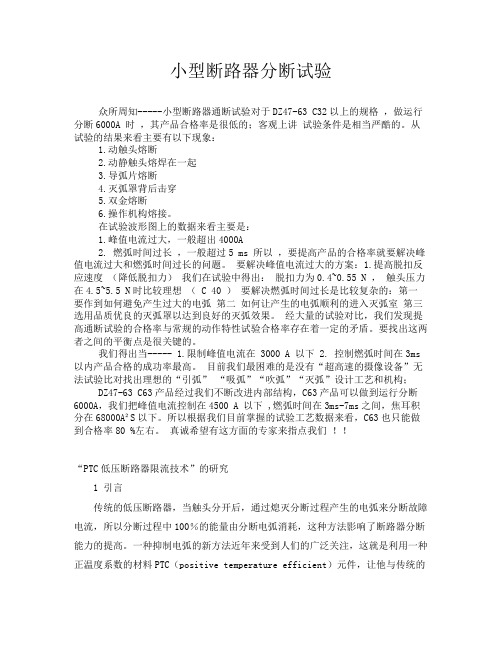
小型断路器分断试验众所周知-----小型断路器通断试验对于DZ47-63 C32以上的规格,做运行分断6000A 时,其产品合格率是很低的;客观上讲试验条件是相当严酷的。
从试验的结果来看主要有以下现象:1.动触头熔断2.动静触头熔焊在一起3.导弧片熔断4.灭弧罩背后击穿5.双金熔断6.操作机构熔接。
在试验波形图上的数据来看主要是:1.峰值电流过大,一般超出4000A2. 燃弧时间过长,一般超过5 ms 所以,要提高产品的合格率就要解决峰值电流过大和燃弧时间过长的问题。
要解决峰值电流过大的方案:1.提高脱扣反应速度(降低脱扣力)我们在试验中得出:脱扣力为0.4~0.55 N ,触头压力在4.5~5.5 N时比较理想( C 40 )要解决燃弧时间过长是比较复杂的:第一要作到如何避免产生过大的电弧第二如何让产生的电弧顺利的进入灭弧室第三选用品质优良的灭弧罩以达到良好的灭弧效果。
经大量的试验对比,我们发现提高通断试验的合格率与常规的动作特性试验合格率存在着一定的矛盾。
要找出这两者之间的平衡点是很关键的。
我们得出当----- 1.限制峰值电流在 3000 A 以下 2. 控制燃弧时间在3ms 以内产品合格的成功率最高。
目前我们最困难的是没有“超高速的摄像设备”无法试验比对找出理想的“引弧” “吸弧”“吹弧”“灭弧”设计工艺和机构;DZ47-63 C63产品经过我们不断改进内部结构,C63产品可以做到运行分断6000A,我们把峰值电流控制在4500 A 以下 ,燃弧时间在3ms-7ms之间,焦耳积分在68000A²S以下。
所以根据我们目前掌握的试验工艺数据来看,C63也只能做到合格率80 %左右。
真诚希望有这方面的专家来指点我们!!“PTC低压断路器限流技术”的研究1 引言传统的低压断路器,当触头分开后,通过熄灭分断过程产生的电弧来分断故障电流,所以分断过程中100%的能量由分断电弧消耗,这种方法影响了断路器分断能力的提高。
PEOPLE ELE. DZ47-63E 小型断路器 说明书

注:①冷态指试验前8h 内没有带负载。
②热态指试验从冷态开始1.13In 负载进行1h 后的状态。
+5过电流脱扣特性t<1h3序号脱扣类型额定电流In (A)试验电流 (A)脱扣时间t预期结果起始状态C.D C所有值所有值脱扣冷态124567≤63A ≤63A ≤32A >32At≤1h 1s<t<60s1s<t<120s t≤0.1s t<0.1s 不脱扣脱扣不脱扣脱扣冷态热态冷态1.13In 1.45In2.55In 5In 10In 10In20InD C D 冷态4.3 大气相对湿度,在最高温度+40℃时不超过50%,在较低温度时可以有较高湿度,例如在 +20℃时,相对湿度为90%,由于温度变化发生在产品表面的凝露应该采取措施。
4.4 断路器使用地点的污染等级为2级。
4.5 断路器的安装类别通常为Ⅱ、Ⅲ类。
5 技术数据5.1 断路器过电压保护值Uvo=280V ±5%。
5.2 过电流脱扣特性:断路器在正常安装条件和基准环境温度30 ℃ 下的过电流脱扣特性应符合下表的规定。
1 用途DZ47-63E 小型断路器(以下简称断路器)主要用于交流50Hz ,额定工作电压为230V ,额定电流至63A,额定短路分断能力不超过6 000A 的配电线路中,作为过载、过压和短路保护用,亦可作为线路不频繁通断操作与转换之用。
断路器按GB10963.1设计、制造与检验。
2 产品型号及其含义 DZ 47 - 63 E带过电压保护壳架等级额定电流(A) 设计序号塑料外壳式断路器3 产品分类3.1 按极数分类有:1P+N 。
3.2 按额定电流分有:1,3,6,10,16,20,25,32,40,50,63A 。
3.3 按额定工作电压分有:230V 。
3.4 按瞬时脱扣器分:有C 型脱扣型式和D 型脱扣型式两种C 型用于配电保护,D 型用于电动机保护。
4 使用的标准工作条件4.1 周围空气温度应不低于-5℃,不高于+40℃,且其24h 内的平均温度值不超过+35℃。
小型断路器规格型号表【大全】

小型断路器也就是小型的空气开关产品,往往被应用于一些类似家庭等等相对范围较为狭窄的场所中,但是它所发挥的作用却很大,因此我们能够得知前期掌握一些关于小型断路器使用操作和维护处理方面知识的必要性。
那么今天为大家普及的信息就是关于小型断路器型号和具体细节含义方面的内容,更进一步还有关于具体例子的分析等等方面文字。
一、小型断路器型号小型断路器(英文名称:Miniature Circuit Breaker)又称微型断路器(Micro Circuit Breaker),适用于交流50/60Hz额定电压230/400V,额定电流至63A线路的过载和短路保护之用,也可以在正常情况下作为线路的不频繁操作转换之用。
小型断路器主要用于工业、商业、高层和民用住宅等各种场所。
该产品应符合GB10963.1、IEC60898标准。
空气开关,又称自动开关,低压断路器。
原理是:当工作电流超过额定电流、短路、失压等情况下,自动切断电路。
DZ47-60A C20的空气开关,这是微(小)型断路器的额定电流标法,英文字表示磁脱扣(短路保护)的动作倍数,C一般用于普通配电(5-10倍),另外一种常见的是D型,用于起动电流较大(如电机)的电器(10-14倍)。
20A表示额定电流,但应注意的是这个电流是在环境温度为40摄氏度时的整定值。
实际使用时可参照厂家提供的降容曲线。
二、DZ47-63-C16小型断路器型号含义DZ是厂家的一个产品系列的代码,63是额定电流,代表这款产品最大型号就到63A的电流。
C16是工作电流。
这是一款适用在照明配电或电机配电的小型断路器。
额定电压可以到400V,如果电路中电流达到或超过16A,会自动跳闸。
主要有C16,C25,C32,C40,C50,C63等几款可供选择,但最大就是63A,如果是超过63A电流的电路,就要用其他系列的产品。
扩展资料:断路器型号规格具体如下:(一)按额定电流分:1、2、3、4、5、6、10、16、16、20、25、32、40、50、60、63、100(A(二)按极数分:单极、二极、三极、四极;(三)按脱扣形式分:C型(5ln~10ln)、D型(10ln~16ln)每个公司的型号都不尽相同,一般说几极几A的就可以。
空气开关问题
我家空气开关(dz47-63-c32/1p)老是无定时的跳闸浏览次数:443次悬赏分:0|解决时间:2011-3-27 20:42 |提问者:daiping6688我家是三室两厅一厨两卫一洗涮间的房子。
去年6月份装修的,一直都好好的,昨天才发现一开关跳闸,请了电工来检查,发现空气开关dz47-63-32/1p坏了,换了之后老是不定时跳闸,怀疑开关质量问题,有换了两个品牌(西门子和德力西)故障依旧,初查线路发现只有大厅和两客房是一路线,空调是专线。
其余房间灯和插座共零线(两卫、厨房、主卧室,洗涮间)总箱未装漏电开关,当时灯火线和插座火线问题补充:共一个c32/1p的开关,昨天查故障时分开装了两个c32/1p的开关,经检查照明回路不跳,只有插座回路跳(不插任何电器的情况下也跳,而且室内总闸DZ47-63-C63/2P会同时跳,电表箱总闸DZ47-63-C63/2P有时同时跳有时不跳)不管加不加用电器故障都是不定时出现,(跳闸时空气开关不发热)最佳答案老是不定时跳闸可能有1、漏电2、过负荷解决办法,找出漏电电器,可找专业电工,如找不到,最简单的方法是把所有电器关掉,一个一个试。
那个接通时跳闸就是那一个。
把大功率电器关掉后如果能正常使用就是过负荷。
你的情况估计是漏电。
分段查一吧。
追问您好!非常谢谢您的关注。
想请教您:如果是漏电,为什么总闸c63/2p会跳?为什么不组成回路的情况下也一样地跳,是插座火线的问题吗?纯空气开关和带漏电空气开关是一样吗?两者对漏电和短路都起相同的作用吗?望再得到您帮助!!回答估计是前后级漏保配合不当。
一般采用二级保护,未级要采用30mA,总闸如果接近就会经常跳。
纯空气开关和带漏电空气开关是不一样的,纯空气开关对漏电不起作用,只对负荷大,电压低,停电,短路有作用,也有二者都有的。
另外有的插座内接线与墙体相接触会有漏电。
带漏电空气开关则有漏保功能。
只有插座回路跳(不插任何电器的情况下也跳,而且室内总闸DZ47-63-C63/2P 会同时跳,电表箱总闸DZ47-63-C63/2P有时同时跳有时不跳)不管加不加用电器故障都是不定时出现,(跳闸时空气开关不发热),还是插座内有漏电处。
德力西 DZ47sZ直流小型断路器 使用说明书
DZ47sZ-63DC MOULDED CASE CIRCUITBREAKERNA VIGATORSeriesUser ManualPlease read the product instructions carefully before the installation and use of the product, and keep those instructions properly for reference later.DZ47sZ-63 DC MOULDED CASE CIRCUIT BREAKERUser ManualSafety NoticePlease carefully read this manual before the installation, operation, run, maintenance, and inspection of the product, and install and operate this product properly according to the product instructions.Danger:●It is prohibited to operate the circuit breaker with your wet hands;●t is prohibited to touch the conductive part during operation;●Make sure that the product is de-electrified during the maintenance and repair;●It is prohibited to use the short circuit method to test the product;Caution●The installation, maintenance, and repair shall be carried out by the qualified professionals;●When installation, connect the wires according to the wiring method shown in Fig. 5 and the “+” and “-” poles marked on the product properly to prevent reverse connection;●All characteristics of the product have been set in the factory, and the product cannot be disassembled without permission or adjusted at will during operation;●Confirm that the operating voltage, rated current and characteristics of the product meet the working requirements before use;●In order to prevent short circuit between the phases, the exposed wire or copper busbar at the terminal block shall be subject to the insulation treatment;●If found any damage or abnormal sound when unpacking, please stop the product and contact the supplier;●When scrapping the product, please dispose the industrial wastes properly. Thanks for your cooperation. About DZ47sZ-63 DC Moulded Case Circuit Breaker●About panelCheck the positive and negative poles,and connect the wires according to thewiring diagram!Fig. 1 Panel introductionLegends:1 Positive pole of circuit2 Terminal block3 Company logo4 Product model (DZ47sZ)5 Rated current (see Table 1)6 Setting current (see Table 1)7 Rated voltage and breaking capacity (see Table 1)8 Certification mark 9 Wiring indication 10 Terminal block 11 Positive pole of circuit breaker12 Reference standard 13 Use category 14 Rated impulse withstand voltageNormal Operation, Installation and Transportation Conditions●Normal operation and installation conditions(1)The upper limit of the ambient air temperature shall not exceed +60°C, the lower limit shall not exceed -20°C, and the mean temperature shall not exceed +35°C within 24 hours;(2)The altitude of the installation site does not exceed 2000m;(3)When the maximum temperature is +40°C, the relative humidity of the air does not exceed 50%; a higher relative humidity is allowed at lower temperatures; for example, the relative humidity does not exceed 90% at +20°C. Special protection measures should be taken for condensation occurred occasionally due to temperature changes;(4)The external magnetic field near the installation site of the circuit breaker should not exceed 5 times of the geomagnetic field in any direction;(5)Installed in a medium without explosion hazard, and there is gas and dust sufficient to cause metal corrosion and damage to the insulation;(6)Installed in places where there is no obvious impact and vibration and no rain and snow attacks;(7)Pollution degree: Level 2;(8)Installation category: Class II, Class III;(9)The product shall be installed in a power distribution tank, distribution cabinet or box;(10)When wiring, the power supply end must be connected to the positive pole of the circuit breaker, the load end must be connected to the negative pole of the circuit breaker, and reverse wiring connection is not allowed;●Normal storage and transportation conditions(1) The lower limit of temperature is not below -40°C, and the upper limit does not exceed +70°C;(2) Relative humidity (at 25°C) does not exceed 95%;(3) Please handle the product gently during transportation, do not upside it down, and prevent it from violent collision as much as possible.Main technical performance parameters●The main technical parameters of the circuit breaker are listed in Table 1.Table 1 Main technical parametersSetting current Rated current In A Numberof polesRated voltageUe VRated breakingcapacity Icn kA(B)Ii=5.5In 6, 8, 10, 13, 16, 20,25, 32, 40, 50, 631 250V62, 3 500V(C)Ii=8.5In 1, 2, 3, 4, 5, 6, 8, 10, 13,16, 20, 25, 32, 40, 50, 631 250V2, 3 500V● The overcurrent protection characteristics of the circuit breaker are listed in Table 2Table 2: Overcurrent protection characteristics of circuit breakers ReleasetypeRatedcurrent InATest current A Starting state Test time Expected results Remarks Referencetemp.(B) Ii=5.5In(C) Ii=8.5In≤631.05In Cold state t ≤1h No trip --+30+50o C(B) Ii=5.5In (C) Ii=8.5In 1.30In Followedby testt<1h TripThe current rises to the specified valuewithin 5s(B) Ii=5.5In 5.5Inx80% Cold statet ≤0.2s No tripTurn on theaux. switch, and connect thepower supply(C) Ii=8.5In 8.5Inx80%(B) Ii=5.5In 5.5Inx120% t<0.2s Trip(C) Ii=8.5In 8.5Inx120%● The protection characteristics curves of circuit breaker are illustrated in Fig. 2 and Fig. 3Fig. 2 B type thermal / electromagnetic tripcharacteristics curve Fig. 3 C type thermal / electromagnetic tripcharacteristics curveOutline and Installation DimensionsThe circuit is rail-mounted, and its outline and installation dimensions are shown in Fig. 4.Unit: mmFig. 4 Outline and installation dimensionsInstallation, Operation and Maintenance●Before installing circuit breaker:(1)Check whether the technical parameters on the label meet the use requirements;(2)Before use, the user should use a 500V megohmmeter to check that the insulation resistance between the poles (except for single pole), the poles and the shells, the poles and the mounting rails, and the inlet and outlet terminals of the circuit breaker should not be less than 5MΩ. If the insulation resistance is less than 5MΩ, stop the product and contact the supplier for replacement in time;(3)Close and open the circuit breaker several times and check whether the circuit breaker operating mechanism is blocked and whether the mechanism works reliably;(4)The reference temperature of this series of circuit breakers is +30+50°C. If there are multiple circuit breakers in the sealed box, the temperature of the box will increase accordingly, and the working current is 0. 8In;(5)The cross-sectional area of the connecting conductor should be adapted to the rated current of the circuit breaker, see Table 3;Table 3: Rated current and cross-sectional area of connecting wiresRated current A 1, 2, 3,4, 5, 610, 13 16, 20 25 32 40, 50 63Sectional area of wire mm2 1 1.5 2.5 4 6 10 16 Min. length of connecting wirem1 1 1 1 1 1 2(6) This series of circuit breakers is of the rail-mounted type, suitable for TH35-7.5 steel mounting rails;(7) When the ambient temperature changes, the rated current value shall be corrected accordingly. Temperature correction coefficients are listed in Table 4.Table 4 Table of temperature coefficients for rated currentRated current Rated current correction value A●Install the circuit breaker according to the wiring method shown in Fig. 5;1P single pole 2P 2 poles 2P 2 poles 2P 2 polesUn (Rated voltage)Lower inlet Upper inlet Lower inlet Upper inlet Lower inlet Upper inlet Lower inlet ApplyLoad3P 3 poles Lower inlet Lower inlet Lower inlet Lower inlet Lower inlet Lower inletUn (Rated voltage)Notes: (1) L+ is the positive pole of power supply, L- is the negative pole of power supply(2) ○+is the positive pole of circuit breaker, and ○-is the negative pole of circuit breaker(3) In the DC power supply, the "L-" is usually earthed, and the neutral pole "M" in the positive and negative power supply system is earthed.Fig. 5 Wiring methodUnpacking InspectionAfter unpacking, the user must check whether the product is intact, whether the exposed metal is rusty, and whether the product is defects due to poor transportation or storage. If found the above phenomenon, please stop the product, and contact the supplier timely for solution.Company’ commitmentThe free repair or replacement will be provided by the company for damage or abnormal operation of the product produced by our company due to poor manufacturing quality within 36 months from the date of the production under the premise that the user conforms to the operation and storage conditions and that the product is well sealed.A paid repair is provided when the warranty period expires. However, the paid repair is provided for damage caused by one of the following situations even within the warranty period:(1)Improper operation, maintenance, or storage;(2)Modification without permission, or improper maintenance;(3)Damage caused by falling off after purchase or occurred during the installation process;(4)Irresistible nature disasters such as earthquakes, fires, lightning strikes, and abnormal voltages.If you have any questions, please contact the dealer or the company’s customer service department.Customer service hotline: 400-826-8008Ordering NoticePlease specify the following contents when ordering:a)Name, model and spec. of circuit breaker;b)Rated current and the number of poles of circuit breaker;c)Qty.For example, to order DZ47sZ-63 1-pole circuit, C type, rated current 20A, 1000 unit, please specify: DZ47sZ-63/1P, C20, 1000 units.Certificate DELIXI ELECTRIC LTD Name: DC Moulded Case Circuit Breaker Model: DZ47sZ-63The product passes the inspection, and is allowed to be shipped.Standard: GB/T 14048.2Inspector: Check 06Date of production: See the label in the inner boxDELIXI ELECTRIC LTDDelixi Industrial Park, Liushi Town, Yueqing City, Zhejiang Province P/C.: 325604 Tel: (86-577)6177 8888Fax: (86-577)6177 8000Customer service hotline: 400-826-8008The first edition of this User Manual was issued in May, 2018.。
正泰 DZ47-60 小型断路器

表2DZ47-60 小型断路器2 型号及含义DZ 47-60壳架等级额定电流 设计序号塑料外壳式断路器DZ47-60小型断路器,主要用于交流50Hz,额定电压至400V,额定电流至63A的线路中起过载、短路保护作用,同时也可以在正常情况下不频繁地通断电器装置和照明线路,但不适用于保护电动机。
符合标准:GB 10963.1、IEC 60898-1,获得CCC认证。
1 适用范围表1参数值230V/400V AC(1P),400V AC(2P、3P、4P)1A、2A、3A、4A、5A、6A、10A、15A、16A、20A、25A、32A、40A、50A、60A、63A 1P、2P、3P、4P C型、D型见表2及图1、图2见表3见表4见表5见表6见表72.0N •m 见图3、图42级IP20Ⅱ、Ⅲ类技术参数项目额定电压额定电流极数瞬时脱扣类型脱扣特性温度补偿系数不同海拔修正系数机械电气寿命额定分断能力连接导线拧紧力矩外形尺寸及安装尺寸污染等级防护等级安装类别3 主要参数及技术性能试验a bce 型式C、D C、DC、D C D试验电流1.13In 1.45In2.55In 10In 16In起始状态冷态紧接着a项试验冷态冷态脱扣或不脱扣时间极限t≤1h t<1h1s<t<60s (In≤32A)t<0.1s 预期结果不脱扣脱扣脱扣脱扣附注电流在5s内稳定地增加终端电器让 电 尽 其 所 能 >> C-028通过闭合辅助开关接通电流项目机械寿命电气寿命寿命(次)40004000表5额定电流C1-C40C1-C40C50-C63C50-C63D1-D63D1-D63极数12、3、412、3、412、3、4电压(V)230/400400230/400400230/400400通断能力(A)600060004000400040004000表6不同海拔高度下使用电流的修正系数脱扣类型C、D 额定电流(A)1、2、3、4、5、6、10、15、16、20、25、32、40、50、60、63≤2000m1(2000-3000)m0.9≥3000m0.8举例额定电流10A产品在2500m降容后使用电流为:0.9×10=9A表4终端电器>>让 电 尽 其 所 能C-029 1-610-3240-631.201.181.161.141.121.121.091.081.071.051.041.031.001.001.000.960.960.970.800.920.870.750.880.830.700.840.80脱扣特性曲线图(见图1、图2)5 外形及安装尺寸35277.56 订货须知6.1 订货时要标明下列各点:6.1.1 产品型号和名称,如DZ47-60小型断路器;6.1.2 瞬时脱扣型式和额定电流,如C25;6.1.3 断路器极数,如2P;6.1.4 订货数量,如50台。
微型断路器型号规格及如何选型【干货】

小型断路器也就是小型的空气开关产品,往往被应用于一些类似家庭等等相对范围较为狭窄的场所中,但是它所发挥的作用却很大,因此我们能够得知前期掌握一些关于小型断路器使用操作和维护处理方面知识的必要性。
那么今天为大家普及的信息就是关于小型断路器型号和具体细节含义方面的内容,更进一步还有关于具体例子的分析等等方面文字。
一、小型断路器型号小型断路器(英文名称:Miniature Circuit Breaker)又称微型断路器(Micro Circuit Breaker),适用于交流50/60Hz 额定电压230/400V,额定电流至63A线路的过载和短路保护之用,也可以在正常情况下作为线路的不频繁操作转换之用。
是建筑电气终端配电装置引中使用最广泛的一种终端保护电器。
用于125A以下的单相、三相的短路、过载、过压等保护,包括单极1P,二极2P、三极3P、四极4P等四种。
微型断路器由操作机构、触点、保护装置(各种脱扣器)、灭弧系统等组成。
其主触点是靠手动操作或电动合闸的。
主触点闭合后,自由脱扣机构将主触点锁在合闸位置上。
过电流脱扣器的线圈和热脱扣器的热元件与主电路串联,欠电压脱扣器的线圈和电源并联。
当电路发生短路或严重过载时,过电流脱扣器的衔铁吸合,使自由脱扣机构动作,主触点断开主电路。
当电路过载时,热脱扣器的热元件发热使双金属片上弯曲,推动自由脱扣机构动作。
当电路欠电压时,欠电压脱扣器的衔铁释放。
也使自由脱扣机构动作小型断路器主要用于工业、商业、高层和民用住宅等各种场所。
该产品应符合GB10963.1、IEC60898标准。
空气开关,又称自动开关,低压断路器。
原理是:当工作电流超过额定电流、短路、失压等情况下,自动切断电路。
DZ47-60A C20的空气开关,这是微(小)型断路器的额定电流标法,英文字表示磁脱扣(短路保护)的动作倍数,C一般用于普通配电(5-10倍),另外一种常见的是D型,用于起动电流较大(如电机)的电器(10-14倍)。
dz47le-d20型号解释
dz47le-d20型号解释
DZ63-C40,DZ47LE-D20,其中断路器DZ63-C40,DZ—塑料外壳式断路器;63—架壳等级额定电流为63A;C—照明保护型;40—断路器的额定电流是40A。
断路器DZ47LE-D20是什么意思:DZ47表示微型塑料外壳,断路器架壳等级额定电流为47A,LE表示带漏电检测功能的,D20表示D型脱扣动力保护型,额定电流是20A。
由于环形变压器属感性负载,类似于电动马达,启动瞬间电流比较大,所以匹配断路器时应充分考虑到此特性。
在选用C型断路器时,一般建议按环形变压器的额定电流的3-4倍来匹配;在选用D型断路器时,一般建议按环形变压器的额定电流的2.5-3倍来匹配。
例如有一台4000W环形变压器,输入是380V,输出24V,那么如何选用断路器呢?选用D型断路器,4000W/380V=10.5A,一般2.5-3倍可以,那就可以用D25的;用C开头的断路器,一般选用3-4倍的,那就可考虑用C40的。
例如有一台2500W环形变压器,输入是220V,输出24V,那么如何选用断路器呢?选用D型断路器,2500W/220V=11.36A,一般2.5-3倍可以,那就可以用D32的;用C开头的断路器,一般选用3-4倍的,
那就可考虑用C40的。
环形变压器一般是隔离型变压器(部分定制的是自耦的),输入与输出是完全隔离的,输出对大地是绝缘的,没有触电危险,开关直接选用断路器即可,不需要带漏电功能的开关。
小型断路器检验标准
小型断路器进货检验、验收及确认检验规范版本A 编号Q/HZE-J07-232-2010一、目的与适用范围为了规范DZ47-63小型断路器的进货检验、验收及确认检验特制定本规程。
本规程适用于DZ47-63小型断路器的进货检验、验收、确认检验及生产、销售、售后服务等过程中发现的不合格品判定。
二、职责2.1 品管部负责编制本规程相关技术人员和体系管理员负责审核、会签最终由管理代表批准。
2.2 检验员负责按本规程进行进货检验、验收及确认检验相关工作。
2.3 生产部负责来货送检、具体试验不合格产品的退换货、及因不合格原因引起索赔等事项。
三、主要内容3.1编制依据 GB10963.1 电气附件家用及类似场所用过电流保护断路器第1部分用于交流的断路器 GB/T 2828.1 计数抽样检验程序第1部分按接收质量限AQL检索的逐批检验抽样计划相应小型断路器的产品图纸及技术要求。
3.2 检验分类检验分为进货检验和确认检验。
3.3 进货检验3.3.1 进货检验采用每批次抽检每批进货数为N应尽可能从不同的大、小包装中抽取样本样本数量为n 具体的抽样数见下面各条款的规定。
3.3.2 进货检验项目 a 外观 b 移印 c 关键尺寸 d 接线可靠性 e 安装可靠性 f 手动操作 g 延时特性—1.13In h 延时特性—1.45In i 延时特性—2.55In j 瞬时特性 k 工频耐压 l 包装。
3.3.3 外观3.3.3.1 抽样数为: N≤7 n N N≥8 n 8。
3.3.3.2 要求外露的塑料件应没有裂纹、色差、气泡、气孔、熔接痕、缩痕、料流痕、银丝、白印、杂色点、拉毛、飞边、色不均、翘曲、分层、损伤等缺陷整机表面应清洁、无损伤。
外露的金属件防腐镀层应光泽没有针孔、麻点、起泡、发黑等缺陷。
产品零部件应齐全符合产品图样要求。
3.3.3.3 检验在1m高40W日光灯下或自然光照条件下裸视力1.0以上目测距离1米、时间2秒钟观察到的缺陷为严重外观缺陷目测距离0.5米、时间3秒钟观察到的缺陷为一般外观缺陷目测距离0.3米、时间5秒钟观察到的缺陷为轻微外观缺陷。
DZ47LE漏电断路器(漏电开关)使用说明书

DZ47LE漏电断路器用途DZ47LE漏电断路器是由DZ47断路器与漏电保护附件拼装而成,适用于交流50Hz、三相400V及单相230V,额定电流至63A的电路中,作为人身触电和设备漏电保护之用,亦可用于线路的过载和短路保护且正常情况下作为线路及电动机的不频繁转换。
该产品分为普通型和银钻型两种,其中银钻型带通断观察窗,并可用汇流排连接。
产品执行标准:GB16917.1家用及类似用途和带过电流保护的剩余电流动作断路器第一部分:一般规则。
主要技术性能与工作原理1、DZ47LE漏电断路器为电流动作型电子式快速漏电断路器,由高导磁材料制造的零序电流互感器、电子组件板,漏电脱扣器和DZ47-63空气开关组成。
当被保护电路有漏电电流或人体间接触电时通过零序电流互感电流的矢量和不等于零,互感器二次线圈的二则产生电压,并经电子元件放大,当达到整定值时,通过漏电脱扣器在0.1秒内切断电源,从而起漏电和漏电保护作用。
2、当被保护线路发生过载或短路时,DZ47-63空气开关自动跳闸,切断电源。
3、DZ47-63空气开关的过电流脱扣器在周围介质温度为+30℃从冷态开始各极同时通电,其动作特性为:a、1.13倍额定电流1h内不动作,b、1.45倍额定电流1h内动作。
4、漏电开关在正常工作中,漏电开关复位按钮应凹下,才正常工作,当复位按钮凸上,证实漏电跳闸。
暂停使用,查明故障方可使用。
5、具体性能见表(1)正常工作条件1、最高空气温度为+40℃,最低空气温度为-5℃;2、海拔高度不超过2000米;3、空气相对温度不大于85%;4、安装位置的外磁场,在任何方向不应超过地磁场的5倍;5、无显著摇动和冲击振动的地方;6、产品必须远离有害、有腐蚀气味环境;7、没有雨雪侵袭的地方。
DZ47Z系列小型断路器

001适用范围DZ47Z 系列小型断路器DZ47Z系列小型断路器适用于直流、额定电压为750V额定电流至63A及以下的电路中作为线路、照明及动力设备的过载与短路保护,也可在正常情况下作线路和设备的不频繁通断转换。
产品符合标准:IEC60898-2、GB/T14048.2。
结构特征本系列断路器由塑料外壳、过电流脱扣器、操作机构、触头及灭弧系统等组成。
外壳采用高强度、高阻燃的塑料压制。
多极断路器由多个单极拼装而成,脱扣器用联动杆相连,手柄用联动罩连成一体,保证了各极通断的一致性。
型号含义DZ 47 Z - □ / □极数壳架等级额定电流直流设计序号塑料外壳式断路器工作条件·海拔高度:安装地点的海拔不超过2000m。
·周围空气温度:周围空气温度上限为+40℃,24h内其平均值不超过+35℃,周围空气温度下 限为-5℃。
·大气条件:安装地点的空气相对湿度在最高温度为+40℃ 时不超过50%,在较低温度下可以 有较高的相对湿度,最湿月的月平均最低温度不超过 +25℃ ,该月的平均最大相对湿度不超 过90%对由于温度变化偶尔产生的凝露应采取相应措施。
·污染等级:2级;·安装类别:Ⅱ、Ⅲ类。
·安装型式:采用TH35-7.5型安装轨安装;·安装角度:安装面与垂直面的倾斜度不超过5°。
主要技术参数注:数据为额定极限短路分断能力Icn。
002托电流时间-动作特性C型脱扣特性曲线(7~15In)图1 DZ47Z-63型断路器C型保护特性曲线接线方法2接线适用于25mm 及以下铜导线连接(见下表),接线方法用螺钉压紧接线,扭矩为2.0N·m。
001外形及安装尺寸图2 DZ47Z-63 小型断路器外形及安装尺寸订货须知订货时需注明断路器的型号、极数、额定电流、瞬时脱扣特性型式;例如:DZ47Z-63二极断路器,瞬时脱扣特性为C型,额定电流20A,数量1000台,则应写为:DZ47Z-63/2、C20、1000台。
DZ47小型断路器DZ47-63
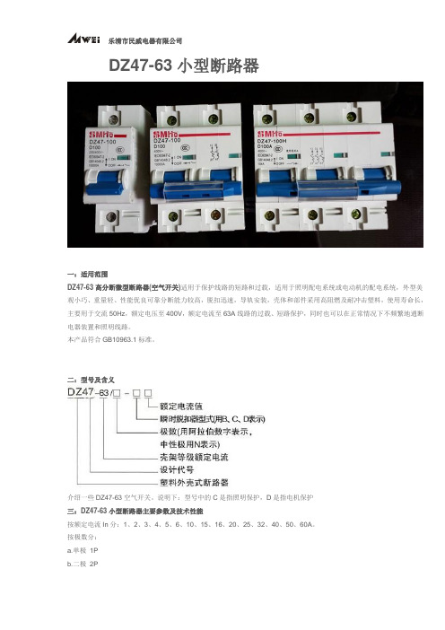
DZ47-63小型断路器一:适用范围DZ47-63高分断微型断路器(空气开关)适用于保护线路的短路和过载,适用于照明配电系统或电动机的配电系统,外型美观小巧、重量轻、性能优良可靠分断能力较高,脱扣迅速,导轨安装,壳体和部件采用高阻燃及耐冲击塑料,使用寿命长,主要用于交流50Hz,额定电压至400V,额定电流至63A线路的过载、短路保护,同时也可以在正常情况下不频繁地通断电器装置和照明线路。
本产品符合GB10963.1标准。
二:型号及含义介绍一些DZ47-63空气开关。
说明下:型号中的C是指照明保护,D是指电机保护三:DZ47-63小型断路器主要参数及技术性能按额定电流In分:1、2、3、4、5、6、10、15、16、20、25、32、40、50、60A。
按极数分:a.单极1Pb.二极2Pc.三极3Pd.四极4P按断路器瞬时脱扣器的型式分:a.C型(5In ~10In);b.D型(10In ~16In)。
技术参数:额定运行短路分断能力(见表1、表2);;机械电气寿命。
a.电气寿命:不低于4000次;b.机械寿命:不低于10000次。
常见的型号有:空气开关C型多用于照明保护,D型多用于电机保护DZ47-63/C5/5A DZ47-63/C6/6A DZ47-63/C10/10A DZ47-63/C15/15A DZ47-63/C16/16ADZ47-63/C20/20A DZ47-63/C25/25A DZ47-63/C32/32A DZ47-63/C40/40ADZ47-63/C50/50A DZ47-63/C60/60ADZ47-63/D5 DZ47-63/D6 DZ47-63/D10 DZ47-63/D15 DZ47-63/D16 DZ47-63/D20DZ47-63/D25 DZ47-63/D32 DZ47-63/D40 DZ47-63/D50 DZ47-63/D60空气开关DZ47-63/4P/C50 DZ47-63/4P/C63四:空气开关特性1.分断能力(见表1)2.DZ47-63空气开关过电流脱扣器保护特性(见表2)3.限流特性DZ47-63系列微型断路器具有高限流能力,从而最大限度的限制了短路所造成的破坏性能(见限流特性图)。
德力西 DZ47v小型标准断路器 说明书

2、3、4 1+N 3+N
1、2、3、4、5、6、8、10、13、16、 1
D型
20、25、32、40、50、63 10、13、16、20、25、32、40、50、63
2、3、4 1+N 3+N
额定电压 Ue V
230/400 400 230 400 230/400 400 230 400 230/400 400 230 400
接线扭紧力矩 N.m
电源端、负载端均为 2.0
f)本系列断路器为导轨安装方式,适用于 TH35-7.5 型钢安装导轨; g)当环境温度发生改变时,其额定电流值相应地予以修正,温度修正系数见表 4;
表 4 额定电流温度-35℃ -20℃ -10℃ 0℃ 10℃ 20℃ 30℃ 40℃ 50℃ 60℃ 70℃
4 5.08 4.89 4.75 4.67 4.48 4.24 4 3.98 3.52 3.25 3.22
5 6.35 6.21 5.98 5.83 5.77 5.42 5 4.85 4.57 4.19 4.05
6 7.62 7.33 7.05 6.84 6.62 6.30 6 5.64 5.42 5.06 4.86
d)本系列断路器的基准温度为 30 ℃,若多个断路器同时装入密封的箱体内,箱体
德力西 DZ47PLEY-63漏电保护断路器 英文说明书

DZ47PLEY-63 Residual Current Operated Circuit-Breaker NAVIGATOR SeriesUser Manual Please carefully read this User Manual before installing and operating the product, and keep this manual properly for future referenceSafety NoticePlease carefully read this instruction before the installation, operation, run, maintenance, and inspection, and follow the contents of the instruction to properly install and operate this product.Danger:⚫Do not operate the circuit breaker with your wet hands;⚫Do not touch the energized parts during operation;⚫Mark sure that the product is de-energized during the maintenance and service;⚫Do not use the short circuit method for product testing;Caution:⚫The installation, maintenance and service shall be performed by the qualified professional;⚫Various characteristics of product have been set in factory and cannot be removed or adjusted without permission during operation;⚫Please confirm that the rated voltage, rated current, frequency and characteristics of the product meet the operating requirements before use;⚫When DZ47PLEY-63 mode adopts upper-inlet wiring method, the wire is led in from the top, and is led out from the bottom; when the lower-inlet wiring method is used, the wire is led in from the bottom, and is led out from the top; please follow the phase sequence when wiring connection, and tighten the wiring screws when the wire inserts into the connecting hole. The wire tightening torque is 2.5N.m to prevent the wire from looseness or being pulled out. The exposed copper wire cannot be out of the wiring terminal;⚫This product cannot provide the protection for electric shock hazard caused by simultaneously touching two lines of protected circuit;⚫With the protection grade IP20, this product has not dust-proof function; when used in a dusty place, this product shall be installed in a well closed terminal box;⚫If found damage or abnormal sound when unpacking, please stop the operation immediately and contact the supplier;⚫After the breaking, overload, or short circuit current fault, please eliminate the fault and then power on this product, otherwise this may affect the service life of the product.⚫Do not use the insulation resistance megger tester to test the insulation resistance between two phases of the power supply of the product circuit board;⚫This product shall be free from rain or water erosion or cannot be fallen off during the operation, storage or transport;⚫This product is not suitable for some special applications such as frequent starts of motor, electric heating equipment, high capacity cabinet, high inductive or high capacitive loads, or high temperature environment;⚫When scrapping the product, please dispose the product waste properly. Thanks for your cooperation.About DZ47PLEY-63 Residual Current Operated Circuit Breaker ● Panel IntroductionLegends:1 Inlet terminal2 Company Logo3 Product model4 Trip curve and rated current (see Table 1)5 Rated voltage and frequency6 Breaking capacity7 Reference standard8 Load end identification9 N pole identification 10 Reset button 11 Wiring diagram12 Rated residual making and breaking capacity, rated residual operated current, current leakage operating time13 Certification mark 14 Test button 15 Outlet terminalLegends:1 Outlet terminal2 Company Logo3 Product model4 Trip curve and rated current (see Table 1)5 Rated voltage and frequency (see Table 1)6 Breaking capacity7 Reference standard8 Load end identification9 N pole identification 10 Reset button 11 Wiring diagram12 Rated residual making and breaking capacity, rated residual operated current, current leakage operating time13 Certification mark 14 Test button 15 Inlet terminalPress before power-onPress once a monthLoad endLoad endPress before power-onPress once a monthNormal Operation, Installation and Transport Conditions●Normal Operation and Installation Conditions(1) Ambient air temperatureThe ambient air temperature is not higher than +70℃, and is not below -35℃, and the average value within 24 hours does not exc eed +35℃;Note: When the residual current operated circuit breaker is used in a place where the ambient air temperature is igher than +70℃ and below -35℃, please contact the manufacturer.(2) AltitudeThe altitude of the installation site does not exceed 2000m;(3) Atmospheric conditionsThe relative humidity of the atmosphere does not exceed 50% when the highest ambient temperature is +60℃, and a higher relative humidity is allowed at lower temperatures, such as 90% at 20℃. Protective measures shall be taken for condensation occasionally occurred due to temperature changes.(4) Installation conditionsThe external magnetic field nearby the residual current operated circuit breaker installation site shall not exceed 5 times earth magnetic field in any direction;The installation position shall be vertical, and the inclination angle at each direction shall not exceed 10°; installed at a place where there is no impact, vibration, and rain or snow erosion;TH35-7.5 steel mounting rail is used for installation.(5) Pollution level: Level 2;(6) Installation category: Class III;(7) Protection grade: IP20 (IP40 if installed in a power distribution box, a power distribution cabinet or tank).(8) For product with a N pole, please connect the zero line to the pole marked with N when wiring.● Normal Storage and Transport Conditions(1) Temperature: -40o C~+70o C;(2) Relative humidity (at 25℃):≤95%(3) During the transport, please handle the product gently, and do not upside it down, and prevent the product from harsh collision;Main Specifications and Technical Parameters ●Main technical parameters are listed in Table 1●Protection characteristics curve of circuit breaker are illustrated in Fig. 1 and Fig. 2Fig. 1 C type thermal/electromagnetic tripcharacteristics curve Fig. 2 D type thermal/electromagnetic tripcharacteristics curveStructure Features and Working PrincipleThis residual current operated circuit breaker primarily consists of zero sequence current transformer, electronic component board, release, contact operating mechanism, and plastic shell.The working principle is shown in Fig. 3. In case of electric leakage or personal electric shock in circuits, when the residual operating current reaches the set value of the operating current, a signal will be generated from the secondary coil of the zero sequence current transformer (induced voltage) to open the residual current operated circuit breaker after amplification by the electronic line, thereby cutting off the power supply for electric leakage protection.Residual current operated circuit breakerZero sequence current transformerTest resistanceElectronic componentboardTest buttonReleaseFig. 3 Working schematic diagram of this residual current operated circuit breakerOutline and Installation DimensionsThe outline and installation dimensions of DZ47PLEY-63 are shown in Fig. 4.Unit: mmFig. 4Product AccessoriesThere are six different accessories in the circuit breaker, including OF auxiliary contact, MX+OF shunt release, SD alarm contact, MV overvoltage release, MN undervoltage release, and MVMN overvoltage and undervoltage release. All accessories are installed on the left side of the product.Installation, Operation and Maintenance●Installation and Operation(1)Before installation, check whether the product marks is consistent with the working conditions.(2)Press the Reset button before power-on.(3)Before power-on, operate the residual current operated circuit breaker several times and check that its mechanism works flexibly and reliably without blockage.(4)The input end shall be connected to the power supply, and the output end shall be connected to the load.(5)The cross-sectional areas of the connecting wire are listed in Table 3.can work reliably.(7)When installation, insert the residual current operated circuit breaker into the mounting rail to fix the residual current operated circuit breaker on this rail without looseness or falling off. To remove the residual current operated circuit breaker, push the circuit breaker upwards to make the upper part of the circuit breaker leave from the mounting rail for removal, or pull the stop block downward for removal.The working reference temperature of the residual current operated circuit breaker is +30+50℃. When the ambient temperature changes, its rating shall be corrected. The temperature correction coefficients are listed in Table 4; if multiple residual current operated circuit breakers are all installed in a closed box, the temperature inside the box will rise, so that the rated current shall multiply by the derating coefficient 0.8.●MaintenanceAfter the residual current operated circuit breaker is running for some time, please check it regularly (monthly). In the power-on state, press the test button and check whether the residual current operated circuit breaker can work reliably. If failed to work normally, please stop the operation and replace it immediatelyFault Analysis and TroubleshootingThe fault analysis and troubleshooting of the residual current operated circuit breaker see Table 5.Table 5 Fault Analysis and TroubleshootingFault Cause SolutionMisoperation Misoperation caused bythe grounding of thezero line at the load sideof the residual currentoperated circuit breakerThe zero line at the load side ofthe residual current operatedcircuit breaker is grounded, whichmay cause misoperation when thenormal operating current passesthrough the grounded pointResidual current operated circuitbreakerIncorrect wiringConnect the ground wire to thezero line of the power side of theresidual current operated circuitbreakerResidual current operated circuitbreakerCorrect wiringMisoperation caused bythe leakage current andwire capacitance currentThe length of the wire layingagainst the ground at the load sideis too longThe residual current operatedcircuit breaker with a largerresidual operating current isselectedEarth leakage current of the wireat the load side increases due tothe reduction of the insulationReplace the wireFailure to operate Failure to operation iscaused by notconnecting the zero lineof the residual currentoperated circuit breakerOnly the phase line of theresidual current operated circuitbreaker is connected, but the zeroline is not connectedConnect the zero line at thepower sideUnpacking InspectionAfter unpacking, please check whether the product is intact, whether the exposed metal is rusty, and whether the product is defected due to poor transport or storage. If found the above phenomenon, please stop the product, and contact the supplier timely for solution.Company CommitmentUnder the condition that users follow the use and storage conditions and the product are well sealed, within 36 months from the production date, our company will provide repair and replacement service free of charge for any damage or abnormal operation due to poor manufacture quality. A paid repair will be provided if the warranty period expires. For any damage due to one of the following situations, a paid repair will be given even if within the warranty period:(1)Improper operation, maintenance, or storage;(2)Modified and improper repair without permission;(3)Damage due to falling off or found during installation after purchase;(4)Force majeure such as earthquakes, fires, lightning strikes, abnormal voltages, and secondary disasters; If you have any question, please contact the dealer or our company’s customer service department.Customer service hotline:400-826-8008Order NoticePlease specify the following items when ordering:1)Name, model and specification of the residual current operated circuit breaker;2)Rated current of the residual current operated circuit breaker;3)Residual operating current of the residual current operated circuit breaker;4)Number of poles;5)Qty.Example 1: To order DZ47PLEY-63 top inlet, C type, rated current 16A, rated residual operating current 30mA, 100 units.Please specify: To order DZ47PLEY-63 top inlet, C16, 30mA, 100 units.Example 2: To order DZ47PLEY-63 bottom inlet, C type, rated current 16A, rated residual operating current 30mA, 100 units.Please specify: To order DZ47PLEY-63 bottom inlet, C16, 30mA, 100 units.CertificateDELIXI ELECTRIC LTDDELIXI ELECTRIC LTDAddress: Delixi High-Tech Industrial Park, Liushi Town, Leqing City, Zhejiang P/C: 325604 Tel: (86-577) 6177 8888Fax: (86-577) 6177 8000Customer Service hotline: 400-826-8008The first edition of this manual was issued on Jan., 2020.。
DZ47系列小型断路器检验标准

数
改为 F=4±1N
脱
开关闭合后,用针式
测力计平行拉动动触
B 头测试部位,使锁扣
脱位,此时测力计读 数为触头终压力; 开关闭合后,用针式 测力计顶在锁扣测力
A类 抽样 方案
扣 1.脱扣力:F≤0.8N;
目标实际测出 F≤1.0N
B 部位,轻力拨动使锁
力
扣脱位,此时测力计
读数为触头脱扣力;
1.直接人为的合分操作 5 次,手柄操作动作灵活,无卡滞、滑 B 人为进行关合与断开 50A
2. 依据作业指导文件准备相关的依据,如检验样品、检验图纸等。 3. 依照作业指导书逐项进行检验(检验项目可根据生产及现场情况提前或调后),并将检验结果
如实填写检验报告。 五、 检验项目及检验方法:
项
等
检验内容与检验要求
目
级
1. 外露塑料件无明显划痕、变形、色差,整机表面光洁,干
净而无灰尘、无污垢。
1. 产品测试前不进行湿热试验,试验期间不得出现击穿或闪
络现象。
施加频率为 50Hz,基
工
表5
本上为正弦波高压,
频 例 行 全 抽检电压: 主触头断开,同一极进线与出线之间
耐 检 电 压 2000V/1min 主触头闭合,极与极之间
压 试
2500V/ 抽检电压:
1s
2500V/1min
主触头闭合,所有的极与框架之间
A类 抽样 方案
拟制
确认
批准
生效日期
顶呱呱 乐清市顶呱呱电气有限公司
标题 DZ47-63 系列小型断路器出厂抽样检验标准
文件编号 文件版本 A.0 页 码 第2页共6页
4. 产品移印标志内容检查依据《小型断路器标志移印图样》。
德力西DZ47标准断路器选型手册

技术参数额定电流:1,2,3,4,5,6,8,10,13 ,16,20,25,32,40,50,63 A 额定工作电压:230/400V AC分断能力符合标准:IEC60898-1 / GB10963.1符合认证:CCC,RoHS 认证脱扣特性B型曲线保护短路电流较小的负载(如电源、长电缆等)脱扣特性:瞬时脱扣范围 (3~5) InC型曲线保护常规负载和配电线缆脱扣特性:瞬时脱扣范围 (5~10) InD型曲线保护起动电流大的冲击性负荷 (如变压器等)脱扣特性:瞬时脱扣范围 (10~14) In361016202532405063136101620253240506313610162025324050631361016202532405063DZ47N1B3DZ47N1B6DZ47N1B10DZ47N1B16DZ47N1B20DZ47N1B25DZ47N1B32DZ47N1B40DZ47L1B50DZ47L1B63DZ47N2B1DZ47N2B3DZ47N2B6DZ47N2B10DZ47N2B16DZ47N2B20DZ47N2B25DZ47N2B32DZ47N2B40DZ47L2B50DZ47L2B63DZ47N3B1DZ47N3B3DZ47N3B6DZ47N3B10DZ47N3B16DZ47N3B20DZ47N3B25DZ47N3B32DZ47N3B40DZ47L3B50DZ47L3B63DZ47N4B1DZ47N4B3DZ47N4B6DZ47N4B10DZ47N4B16DZ47N4B20DZ47N4B25DZ47N4B32DZ47N4B40DZ47L4B50DZ47L4B63181818181818181818183636363636363636363636545454545454545454545472727272727272727272722P3P4PDZ47N1C3DZ47N1C6DZ47N1C10DZ47N1C16DZ47N1C20DZ47N1C25DZ47N1C32DZ47N1C40DZ47L1C50DZ47L1C63DZ47N2C1DZ47N2C3DZ47N2C6DZ47N2C10DZ47N2C16DZ47N2C20DZ47N2C25DZ47N2C32DZ47N2C40DZ47L2C50DZ47L2C63DZ47N3C1DZ47N3C3DZ47N3C6DZ47N3C10DZ47N3C16DZ47N3C20DZ47N3C25DZ47N3C32DZ47N3C40DZ47L3C50DZ47L3C63DZ47N4C1DZ47N4C3DZ47N4C6DZ47N4C10DZ47N4C16DZ47N4C20DZ47N4C25DZ47N4C32DZ47N4C40DZ47L4C50DZ47L4C63DZ47L1D3DZ47L1D6DZ47L1D10DZ47L1D16DZ47L1D20DZ47L1D25DZ47L1D32DZ47L1D40DZ47L1D50DZ47L1D63DZ47L2D1DZ47L2D3DZ47L2D6DZ47L2D10DZ47L2D16DZ47L2D20DZ47L2D25DZ47L2D32DZ47L2D40DZ47L2D50DZ47L2D63DZ47L3D1DZ47L3D3DZ47L3D6DZ47L3D10DZ47L3D16DZ47L3D20DZ47L3D25DZ47L3D32DZ47L3D40DZ47L3D50DZ47L3D63DZ47L4D1DZ47L4D3DZ47L4D6DZ47L4D10DZ47L4D16DZ47L4D20DZ47L4D25DZ47L4D32DZ47L4D40DZ47L4D50DZ47L4D63订货信息注:1.电流规格为2、4、5、8、13 A产品,接受定制,订货号参考编码规则2.若订购符合RoHS认证产品,请在订货号后加“R”小型断路器附件DZ47与断路器拼装示意图当得到信号后,触发与之拼装的断路器脱扣辅助触头基本形式:一常开,一常闭接线能力:1-4mm2导线OF、SD须拼装在断路器左侧,每只断路器左侧仅能拼装一个附件MX+OF拼装在断路器右侧,每只断路器右侧只能拼装一个附件订货信息OFMX+OF9918181818DZ47OFDZ47SDDZ47MX24DZ47MX48DZ47MX110DZ47MX230AC/DC12~24VAC/DC24~48VAC110~127VAC230~400VDZ47/CDB6系列—OF辅助触头/SD报警触头DZ47/CDB6系列—MX+OF 分励脱扣器小型断路器及隔离开关CDB6s 标准断路器DZ47标准断路器CDB2大电流断路器CDB2系列—OF辅助触头/MX+OF分励脱扣器CDB5隔离开关小型断路器及隔离开关CDB6s标准断路器/DZ47标准断路器/DZ47LE标准漏电保护断路器CDB3“相线+中性线”断路器/CDB3LE“相线+中性线”漏电保护断路器。
- 1、下载文档前请自行甄别文档内容的完整性,平台不提供额外的编辑、内容补充、找答案等附加服务。
- 2、"仅部分预览"的文档,不可在线预览部分如存在完整性等问题,可反馈申请退款(可完整预览的文档不适用该条件!)。
- 3、如文档侵犯您的权益,请联系客服反馈,我们会尽快为您处理(人工客服工作时间:9:00-18:30)。
DZ47-63小型断路器
一:适用范围
DZ47-63高分断微型断路器(空气开关)适用于保护线路的短路和过载,适用于照明配电系统或电动机的配电系统,外型美观小巧、重量轻、性能优良可靠分断能力较高,脱扣迅速,导轨安装,壳体和部件采用高阻燃及耐冲击塑料,使用寿命长,主要用于交流50Hz,额定电压至400V,额定电流至63A线路的过载、短路保护,同时也可以在正常情况下不频繁地通断电器装置和照明线路。
本产品符合GB10963.1标准。
二:型号及含义
介绍一些DZ47-63空气开关。
说明下:型号中的C是指照明保护,D是指电机保护
三:DZ47-63小型断路器主要参数及技术性能
按额定电流In分:1、2、3、4、5、6、10、15、16、20、25、32、40、50、60A。
按极数分:
a.单极1P
b.二极2P
c.三极3P
d.四极4P
按断路器瞬时脱扣器的型式分:
a.C型(5In ~10In);
b.D型(10In ~16In)。
技术参数:
额定运行短路分断能力(见表1、表2);;
机械电气寿命。
a.电气寿命:不低于4000次;
b.机械寿命:不低于10000次。
常见的型号有:
空气开关C型多用于照明保护,D型多用于电机保护
DZ47-63/C5/5A DZ47-63/C6/6A DZ47-63/C10/10A DZ47-63/C15/15A DZ47-63/C16/16A DZ47-63/C20/20A DZ47-63/C25/25A DZ47-63/C32/32A DZ47-63/C40/40A
DZ47-63/C50/50A DZ47-63/C60/60A
DZ47-63/D5 DZ47-63/D6 DZ47-63/D10 DZ47-63/D15 DZ47-63/D16 DZ47-63/D20
DZ47-63/D25 DZ47-63/D32 DZ47-63/D40 DZ47-63/D50 DZ47-63/D60
空气开关DZ47-63/4P/C50 DZ47-63/4P/C63
四:空气开关特性
1.分断能力(见表1)
2.DZ47-63空气开关过电流脱扣器保护特性(见表2)
3.限流特性
DZ47-63系列微型断路器具有高限流能力,从而最大限度的限制了短路所造成的破坏性能(见限流特性图)。
五:外形及安装尺寸。
