UDF案例
dataworks python udf函数 实例

dataworks python udf函数实例DataWorks是阿里云提供的一款数据集成和数据开发产品,支持数据的ETL(抽取、转换、加载)和数据协同开发。
在DataWorks中,用户可以使用Python UDF(User-Defined Function,用户自定义函数)来完成一些自定义的数据处理任务。
以下是一个简单的Python UDF函数的示例,该函数可以用于DataWorks中的数据处理:```python#导入必要的库from odps.udf import annotatefrom odps.udf import BaseUDTF#定义UDTF类,继承自BaseUDTF@annotate("string,string")class MyUDTF(BaseUDTF):def process(self,word1,word2):#处理逻辑示例:将两个字符串拆分成单词并输出words1=word1.split()words2=word2.split()#将每个单词输出for word in words1:self.forward(word)for word in words2:self.forward(word)#注册UDTF类my_udtf=MyUDTF()```上述示例是一个简单的DataWorks Python UDF函数,它继承自BaseUDTF类,并定义了一个process方法,用于处理输入的数据。
在这个例子中,输入是两个字符串,函数的处理逻辑是将每个字符串拆分成单词,并将每个单词作为输出。
请注意,实际的Python UDF函数的复杂程度取决于你的需求和数据处理任务。
在实际使用中,你需要根据具体场景进行适当的函数定义和数据处理逻辑。
FLUENT_UDF实例应用ppt课件

;.
6
;.
7
;.
8
#include “udf.h” DEFINE_PRO) {
face_t f; real x; real a=0.01; real g[ND_ND]; begin_f_loop(f,t) { F_CENTROID(g,f,t); x=g[0]; F_PRO)=a*x; } end_f_loop(f,t) }
begin_f_loop(f,thread_out)
{
F_AREA(A,f,thread_out);
sum_A+=NV_MAG(A);
sum_T_A+=NV_MAG(A)*F_T(f,
thread_out);
}
;.
13
end_f_loop(f,thread_out)
;.
14
对并行编程的展望
大部分单核可以运行的UDF在并行下可以完美运行,不过在一些情况下就 不行了,前面的综合编程就是一个很好的例子(Reading and Writing Sums,Certain Loops over cells and faces等情况)。然而现在大部分 PC机或者工作站都是多核,如何写好并行下的UDF是深入模拟领域的关 键。
型)
;.
3
;.
4
3、举一反三 • DEFINE_PROFILE
• #include "udf.h“ DEFINE_PRO) {
real x[ND_ND]; real y; face_t f;
begin_f_loop(f,t) { F_CENTROID(x,f,t); y = x[1]; F_PRO) = 1.1e5 - y*y/(.0745*.0745)*0.1e5; } end_f_loop(f,t) }
【UDF实例】03:温度相关的粘度
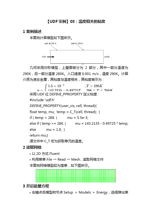
【UDF实例】03:温度相关的粘度1 案例描述本案例计算模型如下图所示。
几何采用对称模型,上壁面被分为2部分,其中一部分温度为290K,另一部分温度280K。
入口速度0.001 m/s,温度290K。
计算介质为液态金属,其粘度与温度相关,其粘度表示为:采用UDF红DEFINE_PPROPERTY定义粘度:#include 'udf.h'DEFINE_PROPERTY(user_vis, cell, thread){float temp, mu; temp = C_T(cell, thread); {if ( temp > 288. ) mu = 5.5e-3;else if ( temp >= 286. ) mu = 143.2135 - 0.49725 * temp;else mu = 1.0; }return mu;}源文件中C_T宏为获取单元的温度。
2 读取网格•以2D方式Fluent•利用菜单File → Read → Mesh…读取网格文件本案例网格模型较为简单,如下图所示。
3 开启能量方程•右键点击模型树节点Setup > Models > Energy,选择弹出菜单On4 加载UDF本UDF可以采用解释方式加载运行。
•右键点击模型树节点Parameters & Customization > User Defined Functions > Interpreted…•在弹出的对话框中点击Browse按钮加载UDF文件viscosity.c •点击按钮Interpret解释UDF并加载5 添加材料•鼠标右键点击模型树节点Materials > Fluid,选择弹出菜单New…•在弹出的对话框中,设置Name为liquid_metal•设置Density为8000 kg/m3•设置Cp为680 j/kg-k•设置Thermal Conductivity为30 w/m-k•设置Viscosity为user-defined,并选择前面加载的udf•点击按钮Change/Create创建材料6 Cell Zone Conditions设置区域内的材料。
udf的并行计算

udf的并行计算摘要:一、引言二、UDF并行计算的概念三、UDF并行计算的优势四、UDF并行计算的实现方法五、UDF并行计算的案例分析六、UDF并行计算的发展趋势七、总结正文:一、引言随着大数据时代的到来,数据处理和分析的需求不断增长。
传统的串行计算方式已经无法满足高效处理大量数据的需求。
在这种背景下,UDF(用户自定义函数)并行计算应运而生,成为大数据处理领域的研究热点。
本文将介绍UDF并行计算的相关知识,探讨其优势、实现方法及发展趋势。
二、UDF并行计算的概念UDF并行计算是一种利用并行计算技术,对用户自定义函数(UDF)进行并行处理的方法。
它将原本串行的UDF函数分解成多个独立的子任务,通过多线程或多进程并行执行这些子任务,从而提高整个计算过程的效率。
三、UDF并行计算的优势UDF并行计算具有以下优势:1.提高计算速度:通过并行处理,可以大幅减少计算时间,提高数据处理效率。
2.充分利用硬件资源:多线程或多进程并行执行,可以充分利用计算机的多核处理器,提高硬件资源利用率。
3.扩展性强:UDF并行计算具有良好的扩展性,可以方便地应用于大规模数据处理场景。
四、UDF并行计算的实现方法UDF并行计算的实现方法主要包括以下几种:1.基于MapReduce的UDF并行计算:利用MapReduce框架将UDF函数分解为多个子任务,通过并行执行这些子任务完成计算。
2.基于Spark的UDF并行计算:利用Spark框架将UDF函数分解为多个子任务,通过并行执行这些子任务完成计算。
3.基于多线程或多进程的UDF并行计算:通过创建多个线程或进程,并行执行UDF函数的各个子任务。
五、UDF并行计算的案例分析以下是一个基于MapReduce的UDF并行计算案例:假设有一个求和UDF,需要对一个包含1000个数的列表进行求和。
使用MapReduce框架,可以将这个求和UDF分解为1000个独立的子任务,每个任务负责计算一个数的和。
FLUENT UDF应用实例:传热热问题第二第三类热边界条件转换成第一类边界条件

FLUENT UDF 应用实例:传热问题第二第三类热边界条件转换成第一类边界条件1 引言传热问题的常见边界条件可归纳为三类,以稳态传热为例,三类边界条件的表达式如下。
恒温边界(第一类边界条件):const w T = (1-1)恒热流密度边界(第二类边界条件):const w T n λ∂⎛⎫-= ⎪∂⎝⎭ (1-2)对流换热边界(第三类边界条件):()w f wT h T T n λ∂⎛⎫-=- ⎪∂⎝⎭ (1-3)2 问题分析2.1 纯导热问题以二维稳态无源纯导热问题为例,如图1所示,一个10×10m 2的方形平面空间,上下面以及左边为恒温壁面(21℃),右边第二类、第三类边界条件如图所示。
为方便问题分析,内部介质的导热系数取1W/m ℃。
模型水平垂直方向各划分40个网格单元,不计边界条件处壁厚。
图1 问题描述采用FLUENT 软件自带边界条件直接进行计算,结果如图2所示。
(a )第二类边界条件(b )第三类边界条件 图2 软件自带边界计算结果参考数值传热学[3],对于第二类(式1-2)、第三类(式1-3)边界条件可通过补充边界点代数方程的方法进行处理,结果如下。
第二类边界条件:11M M q T T δλ-=+(2-1)第三类边界条件:11/1M M fh h T T T δδλλ-⎛⎫⎛⎫=++⎪ ⎪⎝⎭⎝⎭(2-2) 其中,T M 为边界节点处的温度(所求值),T M-1为靠近边界第一层网格节点处的温度,δ为靠近边界第一层网格节点至边界的法向距离,q 为热流密度,h 为对流换热系数。
将以上两式通过UDF 编写成边界条件(DEFINE_PROFILE ),全部转换为第一类边界条件,计算结果如图3所示。
(a)第二类边界条件(b)第三类边界条件图3 UDF计算结果可以看出,经过UDF边界转换后的计算结果与软件自带边界计算结果几乎完全相同。
2.2对流换热问题以上处理方式对于导热问题肯定是适用的,但是对于对流换热问题能否用同样的方式处理呢,笔者认为,严格意义上讲式2-1和2-2对与对流换热问题是不能用的,因为边界内侧的流体与壁面的换热机制是对流换热。
UDF案例

飞昂软件技术(上海)有限公司 ANSYS FLUENT CHINA 2008-12
© 2008 ANSYS, Inc. All rights reserved.
1
ANSYS, Inc. Proprietary
内容概要
• UDS——低Re湍流模型添加 • 动网格 • Degassing Boundary(多相流) • 用户自定义的Drag Law (多相流)
Sk ( Pk ) S C f
2
k2
t
dS[eqn]=-2.*SQR(C_R(c,t)) *C_MU*f_mu(c,t)*C_UDSI(c,t,TKE)/C_MU_T(c,t); • 线性化 return rho_Pk - rho_epsilon; * * } k Sk dS eqn 2 C f k t
© 2008 ANSYS, Inc. All rights reserved.
ANSYS, Inc. Propri “udf.h” const real C_MU=0.09; const real SIG_TDR=1.4; const real SIG_TKE=1.4; const real C1_D=1.5; const real C2_D=1.9; Const real f_1=1.; /* User-defined Scalars */ enum { TKE, TDR, N_REQUIRED_UDS }; real y_star (cell_t c, Thread *t) { return C_R(c,t)*pow(C_UDSI(c,t,TDR)* C_MU_L(c,t)/C_R(c,t), 0.25)*C_WALL_DIST(c,t)/C_M U_L(c, t); } real Re_t (cell_t c, Thread *t) { return C_R(c,t)*C_UDSI(c,t,TKE)*C_ UDSI(c,t,TKE) /C_MU_L(c,t)/C_UDSI(c,t,TDR); }
UDF的宏用法及相关算例

7 自定义函数(UDF)7.1,概述用户自定义函数(User-Defined Functions,即UDFs)可以提高FLUENT程序的标准计算功能。
它是用C语言书写的,有两种执行方式:interpreted型和compiled型。
Interpreted型比较容易使用,但是可使用代码(C语言的函数等)和运行速度有限制。
Compiled型运行速度快,而且也没有代码使用范围的限制,但使用略为繁琐。
我们可以用UDFs来定义:a)边界条件b)源项c)物性定义(除了比热外)d)表面和体积反应速率e)用户自定义标量输运方程f)离散相模型(例如体积力,拉力,源项等)g)代数滑流(algebraic slip)混合物模型(滑流速度和微粒尺寸)h)变量初始化i)壁面热流量j)使用用户自定义标量后处理边界条件UDFs能够产生依赖于时间,位移和流场变量相关的边界条件。
例如,我们可以定义依赖于流动时间的x方向的速度入口,或定义依赖于位置的温度边界。
边界条件剖面UDFs用宏DEFINE_PROFILE定义。
有关例子可以在5.1和6.1中找到。
源项UDFs可以定义除了DO辐射模型之外的任意输运方程的源项。
它用宏DEFINE_SOURCE 定义。
有关例子在5.2和6.2中可以找到。
物性UDFs可用来定义物质的物理性质,除了比热之外,其它物性参数都可以定义。
例如,我们可以定义依赖于温度的粘性系数。
它用宏DEFINE_PROPERTY定义,相关例子在6.3中。
反应速率UDFs用来定义表面或体积反应的反应速率,分别用宏DEFINE_SR_RA TE和DEFINE_VR_RATE定义,例子见6.4。
离散相模型用宏DEFINE_DPM定义相关参数,见5.4。
UDFs还可以对任意用户自定义标量的输运方程进行初始化,定义壁面热流量,或计算存贮变量值(用用户自定义标量或用户自定义内存量)使之用于后处理。
相关的应用见于5.3,5.5,5.6和5.7。
postgresql 的c udf的案例

postgresql 的c udf的案例标题: PostgreSQL的C UDF案例1. 计算两个整数的和```c#include <postgres.h>#include <fmgr.h>PG_FUNCTION_INFO_V1(add_integers);Datum add_integers(PG_FUNCTION_ARGS) {int arg1 = PG_GETARG_INT32(0);int arg2 = PG_GETARG_INT32(1);int result = arg1 + arg2;PG_RETURN_INT32(result);}```2. 计算两个浮点数的乘积```c#include <postgres.h>#include <fmgr.h>PG_FUNCTION_INFO_V1(multiply_floats); Datum multiply_floats(PG_FUNCTION_ARGS) { float arg1 = PG_GETARG_FLOAT4(0);float arg2 = PG_GETARG_FLOAT4(1);float result = arg1 * arg2;PG_RETURN_FLOAT4(result);}```3. 判断一个整数是否为奇数```c#include <postgres.h>#include <fmgr.h>PG_FUNCTION_INFO_V1(is_odd);Datum is_odd(PG_FUNCTION_ARGS) {int arg = PG_GETARG_INT32(0);bool result = arg % 2 != 0;PG_RETURN_BOOL(result);}```4. 将字符串转换为大写```c#include <postgres.h>#include <fmgr.h>#include <ctype.h>PG_FUNCTION_INFO_V1(to_uppercase);Datum to_uppercase(PG_FUNCTION_ARGS) {text* arg = PG_GETARG_TEXT_P(0);int length = VARSIZE(arg) - VARHDRSZ; char* str = VARDATA(arg);for (int i = 0; i < length; i++) {str[i] = toupper(str[i]);}PG_RETURN_TEXT_P(arg);}```5. 计算一个整数的阶乘```c#include <postgres.h>#include <fmgr.h>PG_FUNCTION_INFO_V1(factorial); Datum factorial(PG_FUNCTION_ARGS) { int arg = PG_GETARG_INT32(0);int result = 1;for (int i = 2; i <= arg; i++) { result *= i;}PG_RETURN_INT32(result);}```6. 将字符串按照指定的分隔符进行拼接```c#include <postgres.h>#include <fmgr.h>#include <string.h>PG_FUNCTION_INFO_V1(join_strings);Datum join_strings(PG_FUNCTION_ARGS) {text* arg1 = PG_GETARG_TEXT_P(0);text* arg2 = PG_GETARG_TEXT_P(1);char* delimiter = text_to_cstring(arg1);char* str1 = text_to_cstring(arg2);char* str2 = text_to_cstring(PG_GETARG_TEXT_P(2));int length = strlen(str1) + strlen(str2) + strlen(delimiter) + 1;char* result = palloc(length);snprintf(result, length, "%s%s%s", str1, delimiter, str2);PG_RETURN_TEXT_P(cstring_to_text(result));}```7. 计算一个整数数组中的最大值```c#include <postgres.h>#include <fmgr.h>PG_FUNCTION_INFO_V1(max_integer_array);Datum max_integer_array(PG_FUNCTION_ARGS) {ArrayType* arr = PG_GETARG_ARRAYTYPE_P(0); int* elements = (int*) ARR_DATA_PTR(arr); int num_elements = ARR_DIMS(arr)[0];int max_value = elements[0];for (int i = 1; i < num_elements; i++) { if (elements[i] > max_value) {max_value = elements[i];}}PG_RETURN_INT32(max_value);}```8. 将一个整数数组中的所有元素相加```c#include <postgres.h>#include <fmgr.h>PG_FUNCTION_INFO_V1(sum_integer_array);Datum sum_integer_array(PG_FUNCTION_ARGS) {ArrayType* arr = PG_GETARG_ARRAYTYPE_P(0); int* elements = (int*) ARR_DATA_PTR(arr); int num_elements = ARR_DIMS(arr)[0];int sum = 0;for (int i = 0; i < num_elements; i++) { sum += elements[i];}PG_RETURN_INT32(sum);}```9. 将一个整数数组中的所有元素排序```c#include <postgres.h>#include <fmgr.h>#include <utils/array.h>PG_FUNCTION_INFO_V1(sort_integer_array); Datum sort_integer_array(PG_FUNCTION_ARGS) { ArrayType* arr = PG_GETARG_ARRAYTYPE_P(0); int* elements = (int*) ARR_DATA_PTR(arr);int num_elements = ARR_DIMS(arr)[0];qsort(elements, num_elements, sizeof(int), compare_integers);PG_RETURN_ARRAYTYPE_P(arr);}static int compare_integers(const void* a, const void* b) { int arg1 = *((int*) a);int arg2 = *((int*) b);if (arg1 < arg2) {return -1;} else if (arg1 > arg2) {return 1;} else {return 0;}}```10. 判断一个字符串是否为回文```c#include <postgres.h>#include <fmgr.h>#include <string.h>PG_FUNCTION_INFO_V1(is_palindrome);Datum is_palindrome(PG_FUNCTION_ARGS) {text* arg = PG_GETARG_TEXT_P(0);int length = VARSIZE(arg) - VARHDRSZ;char* str = VARDATA(arg);for (int i = 0; i < length / 2; i++) {if (str[i] != str[length - i - 1]) {PG_RETURN_BOOL(false);}}PG_RETURN_BOOL(true);}```以上是一些基于PostgreSQL的C UDF的案例。
fluent udf案例

fluent udf案例As we know, Fluent UDF (User Defined Function) is a useful tool in Fluent software for creating customized functions to simulate specific physical phenomena or boundary conditions in Fluent simulations. Fluent UDF can be used to extend the capabilities of Fluent software beyond the built-in functions, allowing users to tailor their simulations to their specific needs.正如我们所知,Fluent UDF(用户定义的函数)是Fluent软件中一个有用的工具,用于创建定制函数以模拟Fluent模拟中的特定物理现象或边界条件。
Fluent UDF可以用于扩展Fluent软件的功能,超越内置函数,使用户能够根据自己的需求定制他们的模拟。
One of the key advantages of using Fluent UDF is its flexibility in defining complex boundary conditions or physics models that are not available in the standard Fluent software. With Fluent UDF, users can implement equations, algorithms, or any other custom logic to accurately represent the real-world behavior of their simulations. This flexibility allows users to tackle a wide range of problems that may not be easily solvable using the standard Fluent tools.使用Fluent UDF的一个关键优势是它在定义复杂边界条件或物理模型方面的灵活性,这些在标准Fluent软件中无法实现。
UDF案例

ANSYS, Inc. Proprietary
程序实现
• K方程源项
DEFINE_SOURCE(tke_source, c, t, dS, eqn)
{
Pk t S 2
real rho_Pk, rho_epsilon;
rho_Pk=C_MU_T(c,t)*C_STRAIN_RATE_MAG(c,t)
real y_star (cell_t c, Thread *t)
{
return
C_R(c,t)*pow(C_UDSI(c,t,TDR)* C_MU_L(c,t)/C_R(c,t),
0.25)*C_WALL_DIST(c,t)/C_M U_L(c, t);
}
real Re_t (cell_t c, Thread *t)
return source; }
© 2008 ANSYS, Inc. All rights reserved.
ANSYS, Inc. Proprietary
程序实现
• 扩散项
DEFINE_DIFFUSIVITY(ke_diffusivity, c, t, i)
real diff; real mu_t; int nscalar=i; mu_t=C_R(c,t)*C_MU*f_mu(c,t)*C_UDSI(c,t,TKE)* C_UDSI(c,t,TKE)/C_UDSI(c,t,TDR); if ( nscalar==TKE ) diff=mu_t/SIG_TKE + C_MU_L(c,t); else diff=mu_t/SIG_TDR + C_MU_L(c,t); return diff; }
• 线性化
*C_MU*f_mu(c,t)*C_UDSI(c,t,TKE)/C_MU_T(c,t); return rho_Pk - rho_epsilon;
FLUENT UDF代码_颗粒(煤或生物质)床层多相流燃烧过程数值模拟-【第2部分-完结】

Fluent-UDF_Coal-Combustion-Multiphase-Flow-Processes ---Codes for various kinds of heterogeneous reactions【第二部分-Part2】DEFINE_HET_RXN_RATE(SteamGasif_Rev_MGAS,c,t,hr,mw,yi,rr,rr_t){Thread **pt = THREAD_SUB_THREADS(t);Thread *tp = pt[0]; /* gas phase */int index_phase = Get_Phase_Index(hr);Thread *ts = pt[index_phase]; /* solid phase */*rr = 0;double direction = 0.0, mol_weight, y_carbon, rr_turb = 1e+20;/*CO + H2 ---> H2O + 1/25 SootThe reverse steam gasification reaction, which is CO + H2 ---> 1/25 Soot + H2O is written as the reactionshown above. So a negative rate means CO and H2 is consumed and H2O and Soot are generated. Note that noC(s) is generated, the stoich coeff for C(s) in the above reation is zero.Set the phase and species indices. Ash species index is initialized to zero, with all other indices.Ash species index is used as a flag to execute SetSpeciesIndex only once. This is done by the firstreaction, defined in the heterogeneous reaction panel in FLUENT GUI.*/if(IS_ASH == 0)SetSpeciesIndex();if(MGAS_Gasif){double RoRT = C_R(c,tp) * UNIVERSAL_GAS_CONSTANT * C_T(c,tp);double p_h2o = RoRT * yi[IP_H2O][IS_H2O]/mw[IP_H2O][IS_H2O]/ 101325.;double p_co = RoRT * yi[IP_CO][IS_CO]/mw[IP_CO][IS_CO] / 101325.;double p_h2 = RoRT * yi[IP_H2][IS_H2]/mw[IP_H2][IS_H2] / 101325.;y_carbon = yi[IP_SOOT][IS_SOOT];mol_weight = mw[IP_SOOT][IS_SOOT];if (rp_ke)rr_turb = Turbulent_rr(c, t, hr, yi);if(C_VOF(c, ts) >= eps_s_small){*rr = rr_steam_gasif(c, t, ts, tp, p_h2o, p_co, p_h2, y_carbon, mol_weight, &direction); /* mol/(cm^3 .s) */if( direction > 0.0) /* positive value implies C(s) + H2O ---> CO + H2 */*rr = 0.0;else /* negative value implies CO + H2 ---> H2O + 1/25 Soot */{*rr = abs(*rr);*rr = MIN(*rr, rr_turb);}}}}double rr_steam_gasif(cell_t c, Thread *t, Thread *ts, Thread *tp, double p_h2o, double p_co, double p_h2, double y_carbon, double mol_weight, double* direction){double rate, prod, T_g = MIN((MAX(TMIN,C_T(c,tp))),TMAX);double p_h2o_star = p_h2 * p_co / ( exp(17.29 - 16326/T_g) );if(MGAS_Gasif) *direction = p_h2o - p_h2o_star;if(PCCL_Gasif) *direction = pow(p_h2o, N_steam_gasification)/(1.+K_steam_gasification*p_h2);prod = y_carbon*(C_R(c,ts)*1e-03)/mol_weight*C_VOF(c,ts); /*1e-3 is to convert density from kg/m^3 to g/cm^3 */if(MGAS_Gasif && *direction < 0.0) /* this implies reverse H2O gasification */prod = y_carbon*(C_R(c,tp)*1e-03)/mol_weight*C_VOF(c,tp); /*1e-3 is to convert density from kg/m^3 to g/cm^3 */rate = A_steam_gasification*exp(-E_steam_gasification/Rgas/T_g)* Annealing_steam_gasification * prod * *direction; /* mol/cm^3.s */rate *= 1000.; /* kmol/(m^3 .s) */return rate;}DEFINE_HET_RXN_RATE(Co2Gasif,c,t,hr,mw,yi,rr,rr_t){Thread **pt = THREAD_SUB_THREADS(t);Thread *tp = pt[0]; /* gas phase */int index_phase = Get_Phase_Index(hr);Thread *ts = pt[index_phase]; /* solid phase */*rr = 0;double direction = 0.0, mol_weight, y_carbon;/*C(s) + CO2 ---> 2COSet the phase and species indices. Ash species index is initialized to zero, with all other indices.Ash species index is used as a flag to execute SetSpeciesIndex only once. This is done by the firstreaction, defined in the heterogeneous reaction panel in FLUENT GUI.*/if(IS_ASH == 0)SetSpeciesIndex();double RoRT = C_R(c,tp) * UNIVERSAL_GAS_CONSTANT * C_T(c,tp);double p_co = RoRT * yi[IP_CO][IS_CO]/mw[IP_CO][IS_CO] / 101325.;double p_co2 = RoRT * yi[IP_CO2][IS_CO2]/mw[IP_CO2][IS_CO2] / 101325.;SolidFuel_Reactant(c, t, hr, &y_carbon, &mol_weight);if(C_VOF(c, ts) >= eps_s_small){*rr = rr_co2_gasif(c, t, ts, tp, p_co, p_co2, y_carbon, mol_weight, &direction); /* mol/(cm^3 .s) */if( direction < 0.0) /* negative implies reverse steam gasification */*rr = 0.0;}}DEFINE_HET_RXN_RATE(Soot_CO2_Gasif,c,t,r,mw,yi,rr,rr_t){Thread **pt = THREAD_SUB_THREADS(t);Thread *tp = pt[0]; /* gas phase */*rr = 0;double rr_turb = 1e+20;double T_g = MIN((MAX(TMIN,C_T(c,tp))),TMAX);/*1/25 Soot + CO2 ---> 2COSet the phase and species indices. Ash species index is initialized to zero, with all other indices.Ash species index is used as a flag to execute SetSpeciesIndex only once. This is done by the firstreaction, defined in the heterogeneous reaction panel in FLUENT GUI.*/if(IS_ASH == 0)SetSpeciesIndex();double RoRT = C_R(c,tp) * UNIVERSAL_GAS_CONSTANT * C_T(c,tp);double p_co = RoRT * yi[IP_CO][IS_CO]/mw[IP_CO][IS_CO]/ 101325.;double p_co2 = RoRT * yi[IP_CO2][IS_CO2]/mw[IP_CO2][IS_CO2] / 101325.;if (rp_ke)rr_turb = Turbulent_rr(c, t, r, yi);double prod = yi[IP_SOOT][IS_SOOT]*(C_R(c,tp)*1e-03)/mw[IP_SOOT][IS_SOOT]*C_VOF(c,tp); /*1e-3 is to convert density from kg/m^3 to g/cm^3 */*rr = A_soot_co2_gasification*exp(-E_soot_co2_gasification/Rgas/T_g)* Annealing_soot_co2_gasification * prod *pow(p_co2, N_soot_co2_gasification)/(1.+K_soot_co2_gasification*p_co); /* mol/cm^3.s */*rr *= 1000.; /* kmol/(m^3 .s) */*rr = MIN(*rr, rr_turb);}DEFINE_HET_RXN_RATE(Co2Gasif_Rev_MGAS,c,t,hr,mw,yi,rr,rr_t){Thread **pt = THREAD_SUB_THREADS(t);Thread *tp = pt[0]; /* gas phase */int index_phase = Get_Phase_Index(hr);Thread *ts = pt[index_phase]; /* solid phase */*rr = 0;double direction = 0.0, mol_weight, y_carbon, rr_turb = 1e+20;/*2CO ---> CO2 + 1/25 SootThe reverse CO2 gasification reaction, which is 2CO ---> 1/25 Soot + CO2 is written as the reactionshown above. So a negative rate means CO is consumed and CO2 and Soot are generated. Note that noC(s) is generated, the stoich coeff for C(s) in the above reation is zero.Set the phase and species indices. Ash species index is initialized to zero, with all other indices.Ash species index is used as a flag to execute SetSpeciesIndex only once. This is done by the firstreaction, defined in the heterogeneous reaction panel in FLUENT GUI.*/if(IS_ASH == 0)SetSpeciesIndex();if(MGAS_Gasif){double RoRT = C_R(c,tp) * UNIVERSAL_GAS_CONSTANT * C_T(c,tp);double p_co = RoRT * yi[IP_CO][IS_CO]/mw[IP_CO][IS_CO] / 101325.;double p_co2 = RoRT * yi[IP_CO2][IS_CO2]/mw[IP_CO2][IS_CO2] / 101325.;y_carbon = yi[IP_SOOT][IS_SOOT];mol_weight = mw[IP_SOOT][IS_SOOT];if (rp_ke)rr_turb = Turbulent_rr(c, t, hr, yi);if(C_VOF(c, ts) >= eps_s_small){*rr = rr_co2_gasif(c, t, ts, tp, p_co, p_co2, y_carbon, mol_weight, &direction); /* mol/(cm^3 .s) */if( direction > 0.0) /* positive value implies C(s) + CO2 ---> 2CO */*rr = 0.0;else /* negative value implies 2CO ---> CO2 + 1/25 Soot */{*rr = abs(*rr);*rr = MIN(*rr, rr_turb);}}}}double rr_co2_gasif(cell_t c, Thread *t, Thread *ts, Thread *tp, double p_co, double p_co2, double y_carbon, double mol_weight, double* direction){double T_g = MIN(MAX(TMIN,C_T(c,tp)), TMAX), prod;double p_co2_star = p_co * p_co/(exp(20.92 - 20282/T_g));if(MGAS_Gasif) *direction = p_co2-p_co2_star;if(PCCL_Gasif) *direction = pow(p_co2, N_co2_gasification)/(1. + K_co2_gasification * p_co);prod = y_carbon*C_R(c,ts)*1.e-3/mol_weight* C_VOF(c,ts); /*1e-3 is to convert density from kg/m^3 to g/cm^3 */if(MGAS_Gasif && *direction < 0.0) /* this implies reverse CO2 gasification */prod = y_carbon*(C_R(c,tp)*1e-03)/mol_weight*C_VOF(c,tp); /*1e-3 is to convert density from kg/m^3 to g/cm^3 */double rate = A_co2_gasification*exp(-E_co2_gasification/Rgas/T_g)*Annealing_co2_gasification * prod * (*direction); /* mol/cm^3.s */rate *= 1000.; /* kmol/(m^3 .s) */return rate;}DEFINE_HET_RXN_RATE(H2Gasif,c,t,hr,mw,yi,rr,rr_t){Thread **pt = THREAD_SUB_THREADS(t);Thread *tp = pt[0]; /* gas phase */int index_phase = Get_Phase_Index(hr);Thread *ts = pt[index_phase]; /* solid phase */*rr = 0;double direction = 0.0, mol_weight, y_carbon;/*1/2 C(s) + H2 ---> 1/2 CH4Set the phase and species indices. Ash species index is initialized to zero, with all other indices.Ash species index is used as a flag to execute SetSpeciesIndex only once. This is done bythe firstreaction, defined in the heterogeneous reaction panel in FLUENT GUI.*/if(IS_ASH == 0)SetSpeciesIndex();double RoRT = C_R(c,tp) * UNIVERSAL_GAS_CONSTANT * C_T(c,tp);double p_h2 = RoRT * yi[IP_H2][IS_H2]/mw[IP_H2][IS_H2] / 101325.;double p_ch4 = RoRT * yi[IP_CH4][IS_CH4]/mw[IP_CH4][IS_CH4] / 101325.;SolidFuel_Reactant(c, t, hr, &y_carbon, &mol_weight);if(C_VOF(c, ts) >= eps_s_small){*rr = rr_h2_gasif(c, t, ts, tp, p_h2, p_ch4, y_carbon, mol_weight, &direction); /* mol/(cm^3 .s) */if( direction < 0.0) /* negative implies reverse steam gasification */*rr = 0.0;}}DEFINE_HET_RXN_RATE(Soot_H2_Gasif,c,t,r,mw,yi,rr,rr_t){Thread **pt = THREAD_SUB_THREADS(t);Thread *tp = pt[0]; /* gas phase */*rr = 0;double rr_turb = 1e+20;double T_g = MIN((MAX(TMIN,C_T(c,tp))),TMAX);/*1/25 Soot + 2H2 ---> CH4Set the phase and species indices. Ash species index is initialized to zero, with all other indices.Ash species index is used as a flag to execute SetSpeciesIndex only once. This is done by the firstreaction, defined in the heterogeneous reaction panel in FLUENT GUI.*/if(IS_ASH == 0)SetSpeciesIndex();double RoRT = C_R(c,tp) * UNIVERSAL_GAS_CONSTANT * C_T(c,tp);double p_h2 = RoRT * yi[IP_H2][IS_H2]/mw[IP_H2][IS_H2] / 101325.;if (rp_ke)rr_turb = Turbulent_rr(c, t, r, yi);double prod = yi[IP_SOOT][IS_SOOT]*(C_R(c,tp)*1e-03)/mw[IP_SOOT][IS_SOOT]*C_VOF(c,tp); /*1e-3 is to convert density from kg/m^3 to g/cm^3 */*rr = A_soot_h2_gasification*exp(-E_soot_h2_gasification/Rgas/T_g)* Annealing_soot_h2_gasification * prod *pow(p_h2, N_soot_h2_gasification); /* mol/cm^3.s */*rr *= 1000.; /* kmol/(m^3 .s) */*rr = MIN(*rr, rr_turb);}DEFINE_HET_RXN_RATE(H2Gasif_Rev_MGAS,c,t,hr,mw,yi,rr,rr_t){Thread **pt = THREAD_SUB_THREADS(t);Thread *tp = pt[0]; /* gas phase */int index_phase = Get_Phase_Index(hr);Thread *ts = pt[index_phase]; /* solid phase */*rr = 0;double direction = 0.0, mol_weight, y_carbon, rr_turb = 1e+20;/*1/2 CH4 ---> H2 + (0.5)*1/25 SootThe reverse H2 gasification reaction, which is 1/2 CH4 ---> 1/25 Soot + H2 is written as the reactionshown above. So a negative rate means CH4 is consumed and H2 and Soot are generated. Note that noC(s) is generated, the stoich coeff for C(s) in the above reation is zero.Set the phase and species indices. Ash species index is initialized to zero, with all other indices.Ash species index is used as a flag to execute SetSpeciesIndex only once. This is done by the firstreaction, defined in the heterogeneous reaction panel in FLUENT GUI.*/if(IS_ASH == 0)SetSpeciesIndex();if(MGAS_Gasif){double RoRT = C_R(c,tp) * UNIVERSAL_GAS_CONSTANT * C_T(c,tp);double p_h2 = RoRT * yi[IP_H2][IS_H2]/mw[IP_H2][IS_H2] / 101325.;double p_ch4 = RoRT * yi[IP_CH4][IS_CH4]/mw[IP_CH4][IS_CH4] / 101325.;y_carbon = yi[IP_SOOT][IS_SOOT];mol_weight = mw[IP_SOOT][IS_SOOT];if(C_VOF(c, ts) >= eps_s_small){if (rp_ke)rr_turb = Turbulent_rr(c, t, hr, yi);*rr = rr_h2_gasif(c, t, ts, tp, p_h2, p_ch4, y_carbon, mol_weight, &direction); /* mol/(cm^3 .s) */if( direction > 0.0) /* positive value implies 1/2 C(s) + H2 ---> 1/2 CH4 */*rr = 0.0;else /* negative value implies 1/2 CH4 ---> H2 + (0.5)*1/25 Soot */{*rr = abs(*rr);*rr = MIN(*rr, rr_turb);}}}}double rr_h2_gasif(cell_t c, Thread *t, Thread *ts, Thread *tp, double p_h2, double p_ch4, double y_carbon, double mol_weight, double* direction){double rate = 0.0, prod;double T_g = MIN((MAX(TMIN,C_T(c,tp))), TMAX);double p_h2_star = pow ((p_ch4/(exp(-13.43 + 10999/T_g))), 0.5);prod = y_carbon*C_R(c,ts)*1.e-3/mol_weight * C_VOF(c,ts); /*1e-3 is to convert density from kg/m^3 to g/cm^3 */if(MGAS_Gasif){*direction = p_h2-p_h2_star;if(*direction < 0.0) /* this implies reverse H2 gasification */prod = y_carbon*(C_R(c,tp)*1e-03)/mol_weight*C_VOF(c,tp); /*1e-3 is to convert density from kg/m^3 to g/cm^3 */rate = exp( -7.087 - 8078/T_g )* prod * *direction ; /* mol/cm^3.s */}if(PCCL_Gasif){*direction = p_h2;rate = A_h2_gasification*exp(-E_h2_gasification/Rgas/T_g)*Annealing_h2_gasification * prod * *direction; /* mol/cm^3.s */}rate *= 1000.; /* kmol/(m^3 .s) */return rate;}DEFINE_HET_RXN_RATE(coal_combustion,c,t,hr,mw,yi,rr,rr_t){Thread **pt = THREAD_SUB_THREADS(t);Thread *tp = pt[0]; /* gas phase */int index_phase = Get_Phase_Index(hr);Thread *ts = pt[index_phase]; /* solid phase */double mol_weight, y_carbon, y_ash;*rr = 0.0;/* Set the phase and species indices. Ash species index is initialized to zero, with all other indices.Ash species index is used as a flag to execute SetSpeciesIndex only once. This is done by the firstreaction, defined in the heterogeneous reaction panel in FLUENT GUI.*/if(IS_ASH == 0)SetSpeciesIndex();if( C_YI(c,tp,IS_O2) >= spe_small){SolidFuel_Reactant(c, t, hr, &y_carbon, &mol_weight);y_ash = yi[index_phase][IS_ASH];*rr = rr_combustion(c, t, ts, tp, yi[IP_O2][IS_O2], y_ash, y_carbon); /* mol/(cm^3 .s) */*rr *= 1000.; /* kmol/(m^3 .s) */}}double rr_combustion(cell_t c, Thread *t, Thread *ts, Thread *tp, double yi_O2, double y_ash,double y_carbon){double rd, k_f, k_r, factor, k_a, rate = 0.0, vrel;double Pt = MAX(0.1, (op_pres+C_P(c,t))/101325);double gas_constant = 82.06; /* atm.cm^3/mol.K */double T = C_T(c,tp), T_s = C_T(c,ts), D_p = C_PHASE_DIAMETER(c,ts)*100.;double p_o2 = C_R(c,tp)*UNIVERSAL_GAS_CONSTANT* T *yi_O2/mw[IP_O2][IS_O2] / 101325.; /* atm */if(fc_ar > 0.){if (y_ash > 0.){rd = pow( (y_carbon * ash_ar/100.)/(y_ash * fc_ar/100.), (1./3.) );rd = MIN(1., rd);}elserd = 1.;}elserd = 0.;double diff = MAX((4.26 * pow((T/1800.),1.75)/Pt), 1.e-10); /* cm^2/s */double Sc1o3 = pow(C_MU_L(c,tp)/(C_R(c,tp) * diff * 1.e-4), 1./3.);#if RP_2Dvrel = pow(( (C_U(c,tp)-C_U(c,ts))*(C_U(c,tp)-C_U(c,ts)) +(C_V(c,tp)-C_V(c,ts))*(C_V(c,tp)-C_V(c,ts))), 0.5);#endif#if RP_3Dvrel = pow(( (C_U(c,tp)-C_U(c,ts))*(C_U(c,tp)-C_U(c,ts)) +(C_V(c,tp)-C_V(c,ts))*(C_V(c,tp)-C_V(c,ts)) +(C_W(c,tp)-C_W(c,ts))*(C_W(c,tp)-C_W(c,ts)) ), 0.5);#endifdouble Re = C_VOF(c,tp) * D_p/100. * vrel * C_R(c,tp)/(C_MU_L(c,tp)+SMALL_S);double N_sherwood = (7. - 10. * C_VOF(c,tp) + 5. * C_VOF(c,tp) * C_VOF(c,tp) )*(1. + 0.7 * pow(Re, 0.2) * Sc1o3) +(1.33 - 2.4 * C_VOF(c,tp) + 1.2 * C_VOF(c,tp) * C_VOF(c,tp)) *pow(Re, 0.7) * Sc1o3;if ( rd <= 0. || C_VOF(c, ts) <= 0. ){rate = 0.;}else{k_f = diff * N_sherwood / (D_p * gas_constant/mw[IP_O2][IS_O2] * T ); /* g/(atm.cm^2.s) */k_r = A_c_combustion * exp( -E_c_combustion/Rgas/T_s ) * rd * rd;if ( rd >= 1.){rate = 1. / (1./k_f + 1./k_r);}else{k_a = 2. * rd * diff * f_ep_a / (D_p * (1.-rd) * gas_constant/mw[IP_O2][IS_O2] * T_s );rate = 1. / (1./k_f + 1./k_r + 1./k_a);}factor = y_carbon / (y_carbon + 1.e-6);rate *= p_o2 * 6. * C_VOF(c,ts) * factor / (D_p * 32.); /* mol/(cm^3 .s) */ }return rate;}#if !RP_NODE || !PARALLELvoid volatile_mass_fractions(){read_c3m_data();/* pan2 : Oct 2012 ... added CX_Messages for debugging */CX_Message("PCCL_Devol = %d\n",PCCL_Devol);CX_Message("MGAS_Devol = %d\n",MGAS_Devol);CX_Message("CPD_Devol = %d\n",CPD_Devol);CX_Message("FGDVC_Devol = %d\n",FGDVC_Devol);CX_Message("HPTR_Devol = %d\n",HPTR_Devol);CX_Message("MGAS_Moisture = %d\n",MGAS_Moisture);CX_Message("PCCL_Moisture = %d\n",PCCL_Moisture);CX_Message("MGAS_TarCracking = %d\n",MGAS_TarCracking);CX_Message("PCCL_2nd_Pyro = %d\n",PCCL_2nd_Pyro);CX_Message("MGAS_gasif = %d\n",MGAS_Gasif);CX_Message("PCCL_gasif = %d\n",PCCL_Gasif);CX_Message("PCCL_TarCracking = %d\n",PCCL_TarCracking);CX_Message("MGAS_WGS = %d\n",MGAS_WGS);CX_Message("PCCL_soot_gasif = %d\n",PCCL_soot_gasif);CX_Message("MGAS_char_combustion = %d\n",MGAS_char_combustion);CX_Message("PCCL_char_combustion = %d\n",PCCL_char_combustion);CX_Message("PCCL_soot_oxidation = %d\n",PCCL_soot_oxidation);CX_Message("TAR_oxidation = %d\n",TAR_oxidation);CX_Message("MGAS_gas_phase_oxidation = %d\n",MGAS_gas_phase_oxidation);CX_Message("fc_ar = %f\n",fc_ar);CX_Message("vm_ar = %f\n",vm_ar);CX_Message("ash_ar = %f\n",ash_ar);CX_Message("moist_ar = %f\n",moist_ar);CX_Message("a1_devolatilization = %f\n",A1_devolatilization);CX_Message("e1_devolatilization = %f\n",E1_devolatilization);CX_Message("a2_devolatilization = %f\n",A2_devolatilization);CX_Message("e2_devolatilization = %f\n",E2_devolatilization);CX_Message("a_tar_cracking = %f\n",A_tar_cracking);CX_Message("e_tar_cracking = %f\n",E_tar_cracking);CX_Message("A_steam_gasification = %f\n",A_steam_gasification);CX_Message("E_steam_gasification = %f\n",E_steam_gasification);CX_Message("K_steam_gasification = %f\n",K_steam_gasification);CX_Message("N_steam_gasification = %f\n",N_steam_gasification);CX_Message("Annealing_steam_gasification = %f\n",Annealing_steam_gasification);CX_Message("A_co2_gasification = %f\n",A_co2_gasification);CX_Message("E_co2_gasification = %f\n",E_co2_gasification);CX_Message("K_co2_gasification = %f\n",K_co2_gasification);CX_Message("N_co2_gasification = %f\n",N_co2_gasification);CX_Message("Annealing_co2_gasification = %f\n",Annealing_co2_gasification);CX_Message("A_h2_gasification = %f\n",A_h2_gasification);CX_Message("E_h2_gasification = %f\n",E_h2_gasification);CX_Message("N_h2_gasification = %f\n",N_h2_gasification);CX_Message("Annealing_h2_gasification = %f\n",Annealing_h2_gasification);CX_Message("A_soot_steam_gasification = %f\n",A_soot_steam_gasification);CX_Message("E_soot_steam_gasification = %f\n",E_soot_steam_gasification);CX_Message("K_soot_steam_gasification = %f\n",K_soot_steam_gasification);CX_Message("N_soot_steam_gasification = %f\n",N_soot_steam_gasification);CX_Message("Annealing_soot_steam_gasification= %f\n",Annealing_soot_steam_gasification);CX_Message("A_soot_co2_gasification = %f\n",A_soot_co2_gasification);CX_Message("E_soot_co2_gasification = %f\n",E_soot_co2_gasification);CX_Message("K_soot_co2_gasification = %f\n",K_soot_co2_gasification);CX_Message("N_soot_co2_gasification = %f\n",N_soot_co2_gasification);CX_Message("Annealing_soot_co2_gasification= %f\n",Annealing_soot_co2_gasification);CX_Message("A_soot_h2_gasification = %f\n",A_soot_h2_gasification);CX_Message("E_soot_h2_gasification = %f\n",E_soot_h2_gasification);CX_Message("N_soot_h2_gasification = %f\n",N_soot_h2_gasification);CX_Message("Annealing_soot_h2_gasification = %f\n",Annealing_soot_h2_gasification);CX_Message("A_soot_combustion = %f\n",A_Soot_Combustion);CX_Message("E_soot_combustion = %f\n",E_Soot_Combustion);CX_Message("A_c_combustion = %f\n",A_c_combustion);CX_Message("E_c_combustion = %f\n",E_c_combustion);CX_Message("N_c_combustion = %f\n",N_c_combustion);CX_Message("Annealing_c_combustion = %f\n",Annealing_c_combustion);CX_Message("A_moisture_release = %f\n",A_moisture_release);CX_Message("E_moisture_release = %f\n",E_moisture_release);CX_Message("wg3 = %f\n",wg3);CX_Message("moisture_flux = %f\n",Moisture_Flux);/* f_ep_a is used in shrinking core model, in coal combustion model */double ep_a = 0.25 + 0.75*(1-ash_ar/100.);f_ep_a = pow(ep_a,2.5);}/* pan c3m start */static void SetBooleanValue(char * var , char * svalue) /* pan : Oct 2012 ... new function */ {cxboolean value;if ( strcmp(svalue,"true") == 0) /* pan2 : Oct 2012 : correction */value = TRUE;elsevalue = FALSE;if (strcmp(var,"pccl_devol") == 0) PCCL_Devol = value;if (strcmp(var,"mgas_devol") == 0) MGAS_Devol = value;if (strcmp(var,"cpd_devol") == 0) CPD_Devol = value;if (strcmp(var,"fgdvc_devol") == 0) FGDVC_Devol = value;if (strcmp(var,"hptr_devol") == 0) HPTR_Devol = value;if (strcmp(var,"mgas_moisture") == 0) MGAS_Moisture = value;if (strcmp(var,"pccl_moisture") == 0) PCCL_Moisture = value;if (strcmp(var,"mgas_tarcracking") == 0) MGAS_TarCracking = value;if (strcmp(var,"pccl_2nd_pyro") == 0) PCCL_2nd_Pyro = value;if (strcmp(var,"mgas_gasif") == 0) MGAS_Gasif = value;if (strcmp(var,"pccl_gasif") == 0) PCCL_Gasif = value;if (strcmp(var,"pccl_tarcracking") == 0) PCCL_TarCracking = value;if (strcmp(var,"mgas_wgs") == 0) MGAS_WGS = value;if (strcmp(var,"pccl_soot_gasif") == 0) PCCL_soot_gasif = value;if (strcmp(var,"mgas_char_combustion") == 0) MGAS_char_combustion = value;if (strcmp(var,"pccl_char_combustion") == 0) PCCL_char_combustion = value;if (strcmp(var,"pccl_soot_oxidation") == 0) PCCL_soot_oxidation = value;if (strcmp(var,"tar_oxidation") == 0) TAR_oxidation = value;if (strcmp(var,"mgas_gas_phase_oxidation") == 0) MGAS_gas_phase_oxidation = value;}static void SetValue(char * var , char * svalue) /* pan : oct 2012 ... replace entire function */{char * pEnd;double value = strtod(svalue,&pEnd);if (strcmp(var,"fc_ar") == 0) fc_ar = value;if (strcmp(var,"vm_ar") == 0) vm_ar = value;if (strcmp(var,"ash_ar") == 0) ash_ar = value;if (strcmp(var,"moist_ar") == 0) moist_ar = value;/* NOTE:If the two stage devolatilization model is not used, A2 and E2 have to be set to zero*/if (strcmp(var,"a1_devolatilization") == 0) A1_devolatilization = value;if (strcmp(var,"e1_devolatilization") == 0) E1_devolatilization = value;if (strcmp(var,"a2_devolatilization") == 0) A2_devolatilization = value;if (strcmp(var,"e2_devolatilization") == 0) E2_devolatilization = value;/* if (strcmp(var,"c3m_aem") == 0) c3m_aem = value; should not be used pan : Oct 2012 */if (strcmp(var,"a_tar_cracking") == 0) A_tar_cracking = value;if (strcmp(var,"e_tar_cracking") == 0) E_tar_cracking = value;if (strcmp(var,"a_steam_gasification") == 0) A_steam_gasification = value;if (strcmp(var,"e_steam_gasification") == 0) E_steam_gasification = value;if (strcmp(var,"annealing_steam_gasification") == 0) Annealing_steam_gasification = value;if (strcmp(var,"k_steam_gasification") == 0) K_steam_gasification = value;if (strcmp(var,"n_steam_gasification") == 0) N_steam_gasification = value;if (strcmp(var,"a_co2_gasification") == 0) A_co2_gasification = value;if (strcmp(var,"e_co2_gasification") == 0) E_co2_gasification = value;if (strcmp(var,"annealing_co2_gasification") == 0) Annealing_co2_gasification = value;if (strcmp(var,"k_co2_gasification") == 0) K_co2_gasification = value;if (strcmp(var,"n_co2_gasification") == 0) N_co2_gasification = value;if (strcmp(var,"a_h2_gasification") == 0) A_h2_gasification = value;if (strcmp(var,"e_h2_gasification") == 0) E_h2_gasification = value;if (strcmp(var,"annealing_h2_gasification") == 0) Annealing_h2_gasification = value;if (strcmp(var,"n_h2_gasification") == 0) N_h2_gasification = value;if (strcmp(var,"a_soot_steam_gasification") == 0) A_soot_steam_gasification = value;if (strcmp(var,"e_soot_steam_gasification") == 0) E_soot_steam_gasification = value;if (strcmp(var,"annealing_soot_steam_gasification") == 0) Annealing_soot_steam_gasification = value;if (strcmp(var,"k_soot_steam_gasification") == 0) K_soot_steam_gasification = value;if (strcmp(var,"n_soot_steam_gasification") == 0) N_soot_steam_gasification = value;if (strcmp(var,"a_soot_co2_gasification") == 0) A_soot_co2_gasification = value;if (strcmp(var,"e_soot_co2_gasification") == 0) E_soot_co2_gasification = value;if (strcmp(var,"annealing_soot_co2_gasification") == 0) Annealing_soot_co2_gasification = value;if (strcmp(var,"k_soot_co2_gasification") == 0) K_soot_co2_gasification = value;if (strcmp(var,"n_soot_co2_gasification") == 0) N_soot_co2_gasification= value;if (strcmp(var,"a_soot_h2_gasification") == 0) A_soot_h2_gasification = value;if (strcmp(var,"e_soot_h2_gasification") == 0) E_soot_h2_gasification = value;if (strcmp(var,"annealing_soot_h2_gasification") == 0) Annealing_soot_h2_gasification = value;if (strcmp(var,"n_soot_h2_gasification") == 0) N_soot_h2_gasification = value;if (strcmp(var,"a_soot_combustion") == 0) A_Soot_Combustion = value;if (strcmp(var,"e_soot_combustion") == 0) E_Soot_Combustion = value;if (strcmp(var,"a_c_combustion") == 0) A_c_combustion = value;if (strcmp(var,"e_c_combustion") == 0) E_c_combustion = value;if (strcmp(var,"n_c_combustion") == 0) N_c_combustion = value;if (strcmp(var,"annealing_c_combustion") == 0) Annealing_c_combustion = value;if (strcmp(var,"a_moisture_release") == 0) A_moisture_release = value;if (strcmp(var,"e_moisture_release") == 0) E_moisture_release = value;if (strcmp(var,"c3m_wg3") == 0) wg3 = value;if (strcmp(var,"moisture_flux") == 0) Moisture_Flux = value;/* if (strcmp(var,"c3m_ae5") == 0) c3m_ae5 = value; pan : Oct 2012 ... should not be used */}void read_c3m_data(){CX_Message("start of read_c3m_data \n");FILE * pFile;char line[80];char field1[80];char field2[80];char *pch;int i , field_index;pFile = fopen("fluent_c3m_udf.inp","r");if (pFile != NULL){CX_Message("fopen OK \n");char * pEnd = line;while (pEnd != NULL){/* CX_Message("read a line - start \n"); */pEnd = fgets(line,80,pFile);if (pEnd != NULL){for (i=0; i<80; ++i) line[i] = tolower(line[i]);pch = strtok(line," ,\t\n=");field_index = 0;while (pch != NULL){if (field_index == 0){strcpy(field1,pch);field_index = 1;/* CX_Message("token %s \n",field1); */}else{strcpy(field2,pch);field_index = 0;SetValue(field1,field2);SetBooleanValue(field1,field2); /* pan : Oct 2012 *//*CX_Message("\n\n");CX_Message("token %s \n",field1);CX_Message("token %s \n",field2);*/}pch = strtok(NULL," ,\t\n=");}}}fclose(pFile);}。
fluent中udf提取物理量

Fluent中UDF提取物理量在Fluent中,用户定义函数(UDF)是一种非常强大的工具,可以帮助工程师实现对流体动力学仿真过程中的各种物理量的定制化提取和计算。
本文将深入探讨Fluent中UDF提取物理量的方法和技巧,以便读者更好地理解和应用这一功能。
1. 理解UDF的基本概念我们需要了解什么是UDF以及它在Fluent中的作用。
UDF是用户自定义的函数,可以被Fluent软件识别和调用,用于定制化地描述流体动力学仿真中的各种物理过程。
其中,提取物理量是UDF功能的重要应用之一。
2. UDF提取物理量的基本方法在Fluent中,使用UDF提取物理量的基本方法包括以下几个步骤:- 编写UDF代码:通过Fluent提供的UDF接口,编写能够提取所需物理量的自定义函数代码。
- 编译UDF:将编写的UDF代码进行编译,生成对应的可执行文件。
- 导入UDF:将编译后的UDF文件导入到Fluent软件中。
- 设置物理量提取:在Fluent中设置相应的操作,调用已导入的UDF 文件,实现对所需物理量的提取和计算。
3. 深入探讨UDF提取物理量的实现方式在实际工程应用中,UDF提取物理量的实现方式多种多样,可以根据具体需求进行灵活选择。
常见的实现方式包括但不限于:- 使用已有UDF模板:Fluent软件提供了许多UDF模板,可以直接在其基础上进行修改,实现对所需物理量的提取。
- 编写自定义UDF:根据具体需求,可以编写自定义的UDF代码,实现对特定物理量的提取和计算。
- 借助第三方工具:有些情况下,可以借助第三方工具,将外部计算得到的物理量数据导入到Fluent中进行后续分析。
4. UDF提取物理量的应用案例分析为了更好地理解UDF提取物理量的应用,我们可以通过一个实际案例来进行分析和讨论。
在液体混合槽的流场仿真中,可以利用UDF提取混合槽内各处的速度、压力和浓度等物理量,并进行后续的分析和优化设计。
5. 个人观点和总结从个人角度而言,UDF提取物理量是Fluent中非常重要和实用的功能之一。
UDF的宏用法及相关算例
7 自定义函数(UDF)7.1,概述用户自定义函数(User-Defined Functions,即UDFs)可以提高FLUENT程序的标准计算功能。
它是用C语言书写的,有两种执行方式:interpreted型和compiled型。
Interpreted型比较容易使用,但是可使用代码(C语言的函数等)和运行速度有限制。
Compiled型运行速度快,而且也没有代码使用范围的限制,但使用略为繁琐。
我们可以用UDFs来定义:a)边界条件b)源项c)物性定义(除了比热外)d)表面和体积反应速率e)用户自定义标量输运方程f)离散相模型(例如体积力,拉力,源项等)g)代数滑流(algebraic slip)混合物模型(滑流速度和微粒尺寸)h)变量初始化i)壁面热流量j)使用用户自定义标量后处理边界条件UDFs能够产生依赖于时间,位移和流场变量相关的边界条件。
例如,我们可以定义依赖于流动时间的x方向的速度入口,或定义依赖于位置的温度边界。
边界条件剖面UDFs用宏DEFINE_PROFILE定义。
有关例子可以在5.1和6.1中找到。
源项UDFs可以定义除了DO辐射模型之外的任意输运方程的源项。
它用宏DEFINE_SOURCE 定义。
有关例子在5.2和6.2中可以找到。
物性UDFs可用来定义物质的物理性质,除了比热之外,其它物性参数都可以定义。
例如,我们可以定义依赖于温度的粘性系数。
它用宏DEFINE_PROPERTY定义,相关例子在6.3中。
反应速率UDFs用来定义表面或体积反应的反应速率,分别用宏DEFINE_SR_RA TE和DEFINE_VR_RATE定义,例子见6.4。
离散相模型用宏DEFINE_DPM定义相关参数,见5.4。
UDFs还可以对任意用户自定义标量的输运方程进行初始化,定义壁面热流量,或计算存贮变量值(用用户自定义标量或用户自定义内存量)使之用于后处理。
相关的应用见于5.3,5.5,5.6和5.7。
fluent模拟化学反应的udf例题及联系方式
Fluent模拟化学反应的udf例题及出售联系方式:*******************众所周知,反应器内的诸多化学反应速率方程不一定采用标准阿伦尼乌斯的表达型式,而可能采用双曲线等较为复杂的速率型式。
一旦化学反应速率方程不是标准的阿伦尼乌斯来表达,则Fluent的直接设置不能够满足用户要求,这个时候一定需要c语言等外接程序,才能够获得理想的结果。
鉴于此,本人采用fluen+udf的方法来计算带有化学反应的模拟,读者可以对udf稍加修改即可获得需要的化学反应模拟的要求。
采用fluent的有限速率型式(以下简称:fluent有限速率模型)计算结果作为模拟标准,将fluent外挂udf程序(以下简称:udf反应速率模型)计算与之比较,从而说明本人采用的fluent+udf模拟方法的正确性及准确性。
联系方式:*******************,欢迎探讨!第1页 / 共10页1.反应器结构及边界反应器结构如下图一(二维轴对称结构)。
圆柱形燃烧器内,300K 的甲烷以0.01 m/s 与300K的空气以0.05 m/s速度进入反应器并且发生化学反应,假设其发生的化学反应为:CH4+1.5O2=CO+2H2O反应速率采取r=k*[C CH4]^a*[C O2]^b。
其中:指前因子k=A*e^(-Ea/RT), Ea为活化能;[C CH4]、[C O2]分别为CH4及O2的浓度;a、b为CH4及O2的Rate Exponent。
图一反应器结构及边界条件联系方式:*******************,欢迎探讨!第2页 / 共10页联系方式:*******************,欢迎探讨! 第3页 / 共10页 2. 计算过程监控Fluent 有限速率模型计算的残差曲线监控图,如图二。
图二 Fluent 有限速率模型的曲线监控图更改udf 书写化学方程的残差曲线监控图,如图三。
可以看到,fluent 内添加udf 后,残差会有一个跳跃,但是经过一段时间的计算,各残差恢复稳定。
fluent关于化学反应的udf编写
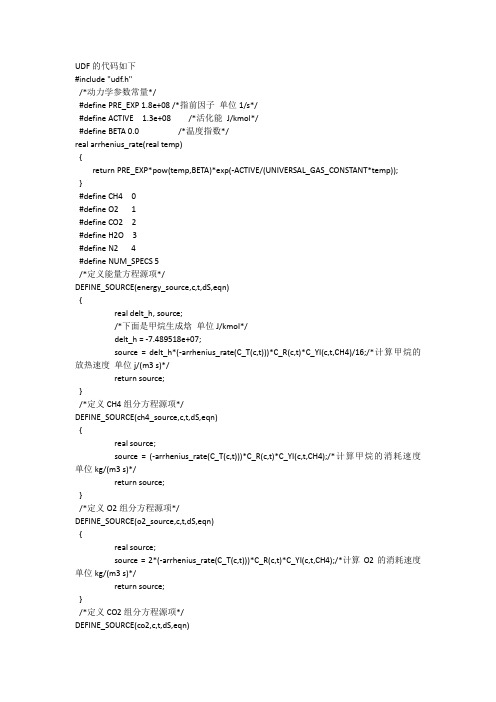
#include "udf.h"
/*动力学参数常量*/
#define PRE_EXP 1.8e+08 /*指前因子 单位 1/s*/
#define ACTIVE 1.3e+08 /*活化能 J/kmol*/
#define BETA 0.0
/*温度指数*/
real arrhenius_rate(real temp)
单位 kg/(m3 s)*/
return source;
}
/*定义 CO2 组分方程源项*/
DEFINE_co2,c,t,dS,eqn)
{ real source; source = (arrhenius_rate(C_T(c,t)))*C_R(c,t)*C_YI(c,t,CH4);/*计算 CO2 的生成速度 单
udf的代码如下includeudfh动力学参数常量definepreexp18e08指前因子单位1sdefineactive13e08活化能jkmoldefinebeta00温度指数realarrheniusraterealtempreturnpreexppowtempbetaexpactiveuniversalgasconstanttemp
/*定义能量方程源项*/
DEFINE_SOURCE(energy_source,c,t,dS,eqn)
{
real delt_h, source;
/*下面是甲烷生成焓 单位 J/kmol*/
delt_h = -7.489518e+07;
source = delt_h*(-arrhenius_rate(C_T(c,t)))*C_R(c,t)*C_YI(c,t,CH4)/16;/*计算甲烷的
「Fluent案例」移动高斯热源

「Fluent案例」移动⾼斯热源移动⾼斯热源常⽤于结构焊接过程模拟。
本案例演⽰在Fluent软件中利⽤UDF定义移动⾼斯热源的过程。
计算结果如下图所⽰。
1 问题描述如下图所⽰,尺⼨为0.1x0.1x0.005m长⽅体,在长⽅体x⽅向边的中部沿着Y⽅向施加⼀个移动热源,热源的速度为0.1m/s,热源为热流密度,值为时间位移函数,如下图所⽰。
热源可表达为:式中Q=4e7w/m2;R=0.005m;v=0.01m/s。
UDF为:2 Fluent设置本案例⽐较简单,这⾥仅列出关键步骤。
2.1 计算⽹格计算⽹格如下图所⽰。
2.2 General设置启⽤Transient选项采⽤瞬态计算2.3 Models设置2.3 Models设置激活能量⽅程2.4 Cell Zone Conditions将计算区域设置为固体域2.5 解释UDF右键选择User Defined Functions,选择Interpreted…选择UDF源⽂件,点击Interpret解释源⽂件2.6 Boundary Conditions设置指定边界的热流密度2.7 取消计算流体⽅程右键选择Controls节点,点击菜单项Equations…弹出的对话框中取消列表项Flow2.8 初始化计算右键选择节点Initialization,点击弹出菜单项Initialize进⾏初始化2.9 Run Calculation如下图所⽰设置时间步长与时间步数,点击Calculate按钮开始计算计算得很快,⽐任何⼀款有限元软件都要快。
3 计算结果表⾯温度分布⽂件⾃助:https:///s/1uhoGiScjsADvvtBBwRON-w提取码:v0i5。
颗粒比热容udf
颗粒比热容UDF1. 什么是颗粒比热容?颗粒比热容是指单位质量的颗粒在吸热或放热过程中所需的热量。
它是描述颗粒热学性质的重要参数,对于颗粒的热传导、热稳定性等热学过程具有重要意义。
2. 颗粒比热容的计算方法颗粒比热容的计算方法可以通过实验测量或者理论推导得到。
实验测量方法通常采用差示扫描量热仪(DSC)等仪器进行测量,通过测量颗粒在不同温度下的热容变化来计算。
理论推导方法则是通过颗粒的物理性质和热学参数来计算,常用的方法有经验公式和数值模拟等。
3. UDF在颗粒比热容计算中的应用UDF(User-Defined Function)是一种用户自定义的函数,可以在计算流体力学(CFD)软件中使用。
在颗粒比热容计算中,UDF可以用来定义颗粒的热学性质和热传导过程。
通过编写UDF,可以实现更加精确的颗粒比热容计算,并考虑到颗粒的特殊性质和非线性效应。
UDF的编写需要使用特定的编程语言,如C或C++。
编写UDF需要熟悉CFD软件的API接口和相关的物理模型。
在编写UDF时,需要定义颗粒的热学性质,如比热容、热导率等,并考虑颗粒的温度变化和热传导过程。
UDF的编写过程需要仔细考虑颗粒的物理性质和热学参数,并进行合理的模拟和计算。
通过编写UDF,可以实现对颗粒比热容的精确控制和计算,提高热传导过程的模拟精度和计算效率。
4. UDF的应用案例UDF在颗粒比热容计算中的应用非常广泛。
以下是一些常见的应用案例:4.1 颗粒混合过程中的热传导在颗粒混合过程中,颗粒之间的热传导起着重要作用。
通过编写UDF,可以模拟颗粒混合过程中的热传导过程,并计算颗粒的比热容。
这对于优化颗粒混合过程、提高产品质量和降低能耗具有重要意义。
4.2 粉体燃烧过程中的热学性质粉体燃烧是一种重要的燃烧方式,颗粒比热容对于粉体燃烧过程的模拟和计算有着重要影响。
通过编写UDF,可以精确计算颗粒的比热容,并考虑颗粒在燃烧过程中的热传导和能量释放等因素。
fluent udf编写案例

fluent udf编写案例Fluent UDF Writing Case1. What is UDF?User Defined Function (UDF) is a custom function written in a programming language, such as JavaScript or Python, that can be used in a streaming data application such as Apache Flink. UDFs can transform, aggregate, filter, or perform calculations on streaming data.2. When to use UDF?UDF can be used in many situations where existing libraries or frameworks don't provide the functionality needed. Some common uses for UDFs include:- Complex data transformations: UDFs can be used to convert raw streaming data into meaningful data fields or to transform existing data fields into new or more useful data formats.- Aggregation and analysis: UDFs can be used to calculate and aggregate data. For example, they can be used to perform time-series analysis, or to calculate complicated statistics on data streams.- Data filtering: UDFs can be used to filter data based on certain criteria, such as only processing messages with certain keywords or a certain value in a numerical field.- Integrating with external APIs: UDFs can be used to integrate external APIs into streaming applications, such as calling a text analysis API on astream of messages, or calling an image analysis API on a stream of images.3. Benefits of UDFUsing UDFs to extend Apache Flink provides several benefits over using native functions, such as:- Flexibility: UDFs allow developers to customize the logic and behavior of a streaming application quickly and easily.- UDFs can be written in multiple languages: UDFs can be written in popular programming languages, such as JavaScript, Java, and Python.- UDFs are scalable: UDFs can be scaled up or down according to the needs of the application.- Reusable components: UDFs can be reused across multiple streaming applications, allowing developers to quickly get up and running with a new streaming application.4. How to write UDFsWriting UDFs for Apache Flink requires some basic knowledge of the language and frameworks used to write the UDF, as well as familiarity with Apache Flink and its APIs and libraries.Some of the basic steps needed to create a UDF are:- Setting up the development environment: UDFs can be written in popular programming languages such as JavaScript, Java, and Python. Appropriate development environments need to be set up to write and debug the UDF. - Writing the UDF: The UDF will need to be written according to the requirements of the streaming application. It will be necessary to understand the data formats and any special requirements of the application.- Debugging and testing the UDF: It is important to thoroughly test and debug the UDF before deploying it to ensure it performs as expected. This is best done with a testing framework such as JUnit.- Deploying the UDF: Once the UDF is written and tested, it can be deployed to Apache Flink for use in streaming applications.5. ConclusionUDFs are an important part of Apache Flink, allowing developers to customize their streaming applications quickly and easily to meet their specific needs. UDFs can be written in popular programming languages, are easy to debug and test, and are easy to deploy. UDFs make it easy to quickly create complex, real-time streaming applications with Apache Flink.。
fluent udf时间判断条件

一、概述在UDF(User Defined Function)开发中,时间判断条件是一个常见的需求。
在数据处理过程中,我们经常需要根据时间进行筛选、计算或者其他操作。
如何在UDF中有效地进行时间判断成为了一个重要的问题。
本文将针对这一问题展开讨论。
二、时间判断条件的需求1. 在数据处理中,我们经常需要根据时间进行筛选。
我们可能需要筛选出某一天内的所有数据,或者某一周、月、季度、年内的数据。
2. 我们可能需要根据时间进行计算。
我们需要计算某一天的数据均值,或者某个时间段内的总和。
3. 我们可能需要根据时间进行其他操作。
根据时间进行分组、排序等。
三、时间判断条件的实现方法1. 使用SQL中的日期函数。
在SQL中,有很多日期函数可以用来实现时间判断条件。
可以使用DATEPART函数获取年、月、日等日期部分,使用DATEADD函数进行日期加减运算,使用DATEDIFF函数计算日期之间的差值等。
2. 使用UDF。
除了SQL中的日期函数外,我们还可以通过编写UDF来实现时间判断条件。
在UDF中,我们可以根据具体的需求,编写相应的逻辑来进行时间判断。
四、使用UDF实现时间判断条件的具体步骤1. 确定需求。
在使用UDF实现时间判断条件之前,首先要明确具体的需求。
我们需要根据日期筛选数据,还是根据日期进行计算,或者进行其他操作。
2. 设计UDF接口。
根据需求,设计UDF的输入参数和返回值。
3. 编写逻辑。
根据设计的接口,编写具体的逻辑来实现时间判断条件。
4. 测试验证。
在编写完UDF之后,进行测试验证,确保UDF能够正常工作。
五、案例分析下面通过一个简单的案例来演示如何使用UDF实现时间判断条件。
假设我们需要编写一个UDF,根据输入的日期判断是否为工作日。
```sqlCREATE FUNCTION dbo.IsWorkDay(date DATE)RETURNS BITASBEGINDECLARE result BITIF (DATEPART(WEEKDAY, date) IN (1, 7))SET result = 0ELSESET result = 1RETURN resultEND```在上面的案例中,我们编写了一个名为IsWorkDay的UDF,接受一个日期作为输入参数,返回一个BIT类型的值。
- 1、下载文档前请自行甄别文档内容的完整性,平台不提供额外的编辑、内容补充、找答案等附加服务。
- 2、"仅部分预览"的文档,不可在线预览部分如存在完整性等问题,可反馈申请退款(可完整预览的文档不适用该条件!)。
- 3、如文档侵犯您的权益,请联系客服反馈,我们会尽快为您处理(人工客服工作时间:9:00-18:30)。
© 2008 ANSYS, Inc. All rights reserved.
ANSYS, Inc. Proprietary
程序实现
• 壁面边界条件 DEFINE_PROFILE(tdr_wall, thread, position) { real xw[ND_ND], xc[ND_ND], delta[ND_ND], dy; face_t f; cell_t c0; Thread *t0=THREAD_T0(thread); begin_f_loop(f,thread) { c0=F_C0(f,thread); C_CENTROID(xc, c0, t0); F_CENTROID(xw, f, thread); NV_VV(delta,=, xc, -, xw); dy=NV_MAG(delta); F_PROFILE(f, thread, position)=2.* ( C_MU_L(c0,t0)/C_R(c0,t0) )*C_UDSI(c0,t0,TKE)/SQR(dy); }end_f_loop(f,thread); }
S
k
f1C1Pk f 2C 2
1 f1C 1Pk 2 f 2C 2 k
dS eqn
© 2008 ANSYS, Inc. All rights reserved.
ANSYS, Inc. Proprietary
程序实现
• 扩散项
DEFINE_DIFFUSIVITY(ke_diffusivity, c, t, i) real diff; real mu_t; int nscalar=i; mu_t=C_R(c,t)*C_MU*f_mu(c,t)*C_UDSI(c,t,TKE)* C_UDSI(c,t,TKE)/C_UDSI(c,t,TDR); if ( nscalar==TKE ) diff=mu_t/SIG_TKE + C_MU_L(c,t); else diff=mu_t/SIG_TDR + C_MU_L(c,t); return diff; }
Sk ( Pk ) S C2.*SQR(C_R(c,t)) *C_MU*f_mu(c,t)*C_UDSI(c,t,TKE)/C_MU_T(c,t); • 线性化 return rho_Pk - rho_epsilon; * } * k Sk dS eqn 2 C f t k
cg_omega[0] = 0.0; cg_omega[1] = 0.0; cg_omega[2] = omega; }
© 2008 ANSYS, Inc. All rights reserved.
ANSYS, Inc. Proprietary
DEFINE_GRID_MOTION
DEFINE_GRID_MOTION(moving_arc, domain, dt, time, dtime) { Thread *tf = DT_THREAD (dt); face_t f; Node *node_p; real alpha, theta, x, ymag, yfull, y; int n; SET_DEFORMING_THREAD_FLAG (THREAD_T0 (tf)); alpha = omega * CURRENT_TIME; theta = 2.0 * alpha + 3.0 * M_PI / 2.0; begin_f_loop (f, tf) { f_node_loop (f, tf, n) { node_p = F_NODE (f, tf, n); if (NODE_POS_NEED_UPDATE (node_p)) { NODE_POS_UPDATED (node_p);
程序实现
• K方程源项
Pk t S 2
S 2Sij Sij
1/ 2
DEFINE_SOURCE(tke_source, c, t, dS, eqn) { real rho_Pk, rho_epsilon; rho_Pk=C_MU_T(c,t)*C_STRAIN_RATE_MAG(c,t) *C_STRAIN_RATE_MAG(c,t); rho_epsilon = SQR(C_R(c,t))*C_MU*f_mu(c,t) * C_UDSI(c,t,TKE)*C_UDSI(c,t,TKE) /C_MU_T(c,t);
© 2008 ANSYS, Inc. All rights reserved.
ANSYS, Inc. Proprietary
程序实现
real f_mu (cell_t c, Thread *t) { return SQR(1. - exp(-y_star(c,t)/14.))*(1.+ 5./pow(Re_t(c,t), 0.75)* exp( -SQR(Re_t(c,t)/200.) )); }
x = NODE_X (node_p); ymag = sqrt (R*R - x*x) + 0.03; yfull = ymag - 0.1; y = - 0.1 + yfull * sin(theta); NODE_Y (node_p) = y;
}
}
} end_f_loop (f, tf); }
© 2008 ANSYS, Inc. All rights reserved.
ANSYS, Inc. Proprietary
UDS——低Re湍流模型添加
© 2008 ANSYS, Inc. All rights reserved.
3
ANSYS, Inc. Proprietary
问题描述
• 通过UDF添加低雷诺数模型,AKN model (Abe, Kondoh, Nagano(IJHMT, 1995)) • 需要添加k和epsion两个方程
FLUENT UDF案例
飞昂软件技术(上海)有限公司 ANSYS FLUENT CHINA 2008-12
© 2008 ANSYS, Inc. All rights reserved.
1
ANSYS, Inc. Proprietary
内容概要
• UDS——低Re湍流模型添加 • 动网格 • Degassing Boundary(多相流) • 用户自定义的Drag Law (多相流)
14
ANSYS, Inc. Proprietary
问题运动
• 绿色的阀体作定速转动 • 黄色膜片作随时间做正/余旋 的变形 • 动网格区域 – 阀体—— DEFINE_CG_MOTION – 膜片—— DEFINE_GRID_MOTION – 上部壁面—— DEFINE_GEOM
© 2008 ANSYS, Inc. All rights reserved.
壁面边界条件:
© 2008 ANSYS, Inc. All rights reserved. ANSYS, Inc. Proprietary
需要用到的数据宏
• 密度 C_R(c,t) • 层流黏度 C_MU_L(c,t) • 湍动能 C_UDSI(c,t,TKE) • 湍流耗散率 C_UDSI(c,t, TDR) • 平均速度应变率 C_STRAINRATE_MAG(c,t) • 湍流黏度 C_MU_T(c,t)
© 2008 ANSYS, Inc. All rights reserved.
ANSYS, Inc. Proprietary
程序实现
• Epsilon方程源项及其线性化
DEFINE_SOURCE(tdr_source, c, t, dS, eqn) { real Pk, source; Pk = C_MU_T(c,t)/C_R(c,t)* SQR(C_STRAIN_RATE_MAG(c,t)); dS[eqn]=C1_D*f_1*Pk/C_UDSI(c,t,TKE) -2.*C_R(c,t)*C_UDSI(c,t,TDR)* f_2(c,t)*C2_D/C_UDSI(c,t,TKE); source=C_R(c,t)*C_UDSI(c,t,TDR)/ C_UDSI(c,t,TKE)*( f_1*C1_D*PkC2_D*f_2(c,t)*C_UDSI(c,t,TDR)); return source; }
real f_2(cell_t c, Thread *t) { return SQR( 1.0 - exp(-y_star(c,t)/3.1 )) *(1.-0.3*exp(SQR(Re_t(c,t)/6.5))); }
© 2008 ANSYS, Inc. All rights reserved.
ANSYS, Inc. Proprietary
© 2008 ANSYS, Inc. All rights reserved. ANSYS, Inc. Proprietary
程序实现
© 2008 ANSYS, Inc. All rights reserved.
ANSYS, Inc. Proprietary
动网格UDF案例
© 2008 ANSYS, Inc. All rights reserved.
© 2008 ANSYS, Inc. All rights reserved.
ANSYS, Inc. Proprietary
程序实现
#include “udf.h” const real C_MU=0.09; const real SIG_TDR=1.4; const real SIG_TKE=1.4; const real C1_D=1.5; const real C2_D=1.9; Const real f_1=1.; /* User-defined Scalars */ enum { TKE, TDR, N_REQUIRED_UDS }; real y_star (cell_t c, Thread *t) { return C_R(c,t)*pow(C_UDSI(c,t,TDR)* C_MU_L(c,t)/C_R(c,t), 0.25)*C_WALL_DIST(c,t)/C_M U_L(c, t); } real Re_t (cell_t c, Thread *t) { return C_R(c,t)*C_UDSI(c,t,TKE)*C_ UDSI(c,t,TKE) /C_MU_L(c,t)/C_UDSI(c,t,TDR); }
