丹弗斯PVG32系列比例多路阀样本
丹佛斯PVG 100比例阀中文样本

修订内容 更改代码 新的封底 添加4页: 应用安全章节 大幅修订 大幅修订
版本号 CD CF DA DB EA
样本修订
PVG产品的样本修订
名称 PVG 32 农机模块-公制油口 PVG 100 比例阀 PVG 120 比例阀 PVBZ 基本模块 PVSK 模块,集成了分流和P口切断功能 PVED-CC 电控模块 PVED-CX 电控模块,系列 4 PVE 系列 4 PVPV / PVPVM 泵侧模块 PVHC 电控模块,用于PVG32和PVG100 PVGI 过渡模块 PVSP/M 优先模块 PVBM “Meter-in” “Meter-out” 模块 类型 产品样本 维修手册 产品样本 产品样本 产品样本 产品样本 产品样本 产品样本 产品样本 产品样本 产品样本 产品样本 样册 代码 11051935 11048807 520L0356 520L0721 520L0556 520L0665 11070179 520L0553 520L0222 11064912 520L0405 520L0291 L1117392
PVG 100 功能
PVG 100 阀组带开芯 PVPF .............................................................................................................................................9 PVG 100 阀组带闭芯 PVPV / PVPVP / PVPVM ....................................................................................................... 11 PVG 100 闭芯转向优先模块 PVPVP ................................................................................................................. 12 PVG 100 闭芯模块 PVPVM ................................................................................................................................... 12 PVG 100 工作模块 PVB ........................................................................................................................................... 12 PVG 100 回油模块 ................................................................................................................................................... 12 负载敏感控制................................................................................................................................................................... 14 远程压力补偿控制 ......................................................................................................................................................... 15 远程压力补偿系统特性: ........................................................................................................................................ 15 典型实例:远程压力补偿系统........................................................................................................................... 15 PVG 100 主阀芯,带压力补偿控制......................................................................................................................... 16 压力补偿系统特性 ................................................................................................................................................... 16 典型实例:压力补偿系统 .................................................................................................................................... 16 PVMR, 摩擦定位 .............................................................................................................................................................. 17 PVMF, 机械浮动位置锁定. ......................................................................................................................................... 17 PVBS, 流量控制主阀芯 (标准)................................................................................................................................. 18 PVBS, 流量控制主阀芯 (线性特性) ............................................................................................................................. 18 安全建立 ............................................................................................................................................................................ 19 FMEA (故障模式及影响分析) IEC EN 61508 ................................................................................................... 19 故障模式及影响分析 ISO 12100-1 / 14121..................................................................................................... 19 实例:控制系统. ........................................................................................................................................................... 20 PVG 100 – LS卸荷或先导油切断可选 ............................................................................................................... 22
丹佛斯压缩机速查手册(32P)
FR8.5GX 195B0026 103G6780
84.9 123 171 228 298 381 478 592 722
151 231 321
FR10GX
195B0024 103G6880
91.9 136 188 250 324 412 516 638 779
179 265 362
FR11GX
195B0028 103G6980
3
速查手册
活塞式压缩机 R134a
代码
EN 12900 (CECOMAF) 制冷量 [W]
EN 12900 (CECOMAF) 功率消耗 [W]
应用
HBP / MBP / (LBP)
压缩机
压缩机代码 压缩机 单个包装 代码
蒸发温度 [°C]
蒸发温度. [°C]
-35 -30 -25 -20 -15 -10 -5
推动技术变革 借助于不断的技术创新,丹佛斯通过提供高效、环保、低噪的产品来 为客户创造价值。
产品全,应用广 丹佛斯提供使用各种常见HFC、HCFC制冷剂的活塞压缩机和涡旋压 缩机。
涡旋压缩机 丹佛斯涡旋压缩机集高能效、超静音和高稳定性等优点于一身,冷量范围广,适用于轻商用到大型商用空调系统的R407C,R134a,R410A和R22的 单机和并联机一应俱全。
ptc启动启动继电器启动器盖子夹子垫片部分压缩机启动电容线夹电容运行电l2l1速查手册活塞式压缩机r404ar507压缩机制冷剂应用压缩机压缩机代码压缩机代码单个包装195b0021195b0031195b0038195b0350195b0151195b0379195b0399195b0332195b0070195b0427195b0439195b0443195b0345195b0323195b0391195b0392195b0436195b0437195b0438195b0166195b0032195b0075195b0077195b0089195b0111195b0112195b0113102u2071103u2670103u2890105f3710104l2533104l2623104l2853104l2123104l2322107b0500107b0501105f3720104l2506104l2606104l2869104l2139107b0502107b0503107b0504102u2038103u2680104l2525104l2625104l2856104l4091104l4092104l40934552779910258167226325406510812614614015127132549772135841451681991662372993954557039863011018922226325535345254261794912972514224329034036049061571581312401663201823073724304836507929181042158020925466698299681535192519631747160975994312171518en12900cecomaf制冷量1523038346853662583598811541306197425775266878381038121014191917239722938561180696412221612192810286473577657789104812081425160624273120645855103812851497177723652952281471775102812071550205524145352578796977129114581735119014301015tl4clxfr6clxfr85
PVG 32培训Chinese

P-口: 350 (400) Bar A/B 口: 380 Bar T 口: 25/40 Bar
流量:
P-口 150 l/min P-口 230 l/min (中间进油) A/B 口 130 l/min 不带补偿器可到160 l/min
20
PVG 32 功能
240 bar
油缸移动
260 bar
叠加阀操作
PVG 阀的电子控制
31
PVG 阀培训
PVE PVG 阀的电子控制
• PVHC
PVG的电子控制 – 非PVE 电流控制 阀芯位置没有闭环控制 12V和24V 可选
32
PVG 32 / 120
详细说明 PVG
• • • • • • 客户指定他们自己的阀 灵活的标准化设计 每张参数清单都是唯一的 超过80.000种客户阀类型 1–12 联 PVG32 PVG32和PVG 120间可联用(4 联 PVG 120 & 8 联 PVG 32) • PVG32 和 PVG100 间可联用
PVE
PVLP
PVS
PVE - DI PVH PVLA PVLP PVM PVMD
PVBS PVB
PVP
PVMF PVMR PVPC
PVM
PVPX PVS
23
PVG 32
PVGI – PVG 32/PVG 120 联用
用一个连杆组件将PVG120进油口和PVB进油口连接到 PVGI模块(在上方油箱模块中使用)。 用第二个连杆组件将PVG32 PVBs和PVS连接到PVGI模 块。 PVG 32 PVGI PVG120
33
quetions
34
谢谢
35
指定组合 /组号 (现在: 11xxxxxx no.) 溢流压力设置 (bar) 条形码 + 日期码 / 制造和测 试日期 制造中心代码
PVG32-多路阀智能测试试验台设计
PVG32-多路阀智能测试试验台设计张湛;杨林兴;孟轩【摘要】现今PVG32比例控制多路阀在工程机械设备中广泛使用。
根据PVG32多路阀的特点,设计了全性能液压测试和控制试验系统的试验台。
该设计采用了针对性强,多工况负载选择和计算机辅助试验的方法。
试验台得到的测试数据更加全面真实,试验过程方便快捷,试验结果对实际使用具有指导作用。
%Today, the PVG32 proportional control multi-way valve has been widely used in engineering equip-ment. According to the characters of PVG32, this paper would like to offer a practical design of a hydraulic electri-cal-control test system. The designed system adopts a multi-load, computer-aided test method which has strong perti-nence. This test system can provide more complete and accurate test result, and very easy to use. It can be used as a helpful reference for actual usage of PVG 32.【期刊名称】《流体传动与控制》【年(卷),期】2014(000)004【总页数】3页(P32-34)【关键词】比例控制多路阀;试验台;智能测试;检测控制【作者】张湛;杨林兴;孟轩【作者单位】北京天顺长城液压科技有限公司北京 100083;北京天顺长城液压科技有限公司北京 100083;北京天顺长城液压科技有限公司北京 100083【正文语种】中文【中图分类】TH137.52当今在各种工程机械设备中,为达到节能环保优化控制,比例控制多路阀已被越来越多的使用。
Danfoss热力膨胀阀样本参数
Danfoss A/S (RC-CM/hbs), 10 - 2002
RK0YP102
3
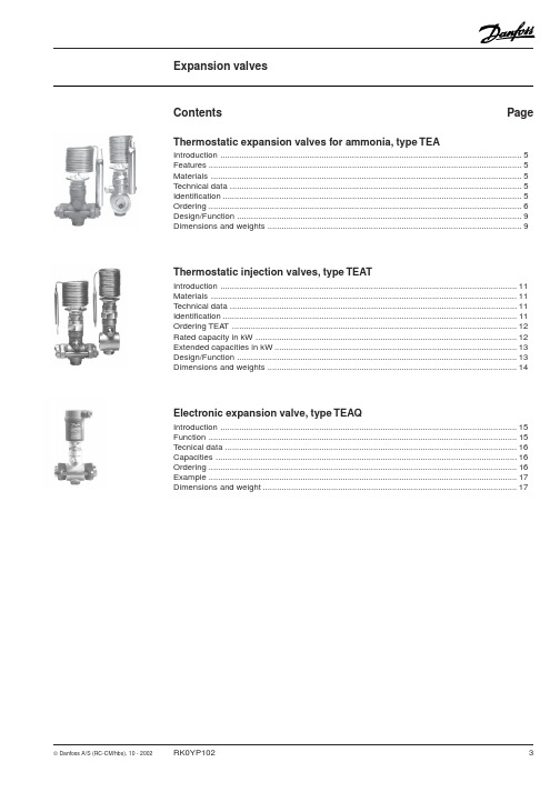
Introduction
Thermostatic expansion valves for ammonia type TEA
Thermostatic expansion valves regulate the injection of refrigerant liquid into evaporators. Injection is controlled by the refrigerant superheat.
Thermostatic injection valves, type TEAT
Introduction .............................................................................................................................. 11 Materials .................................................................................................................................. 11 Technical data .......................................................................................................................... 11 Identification ............................................................................................................................. 11 Ordering TEAT ......................................................................................................................... 12 Rated capacity in kW ............................................................................................................... 12 Extended capacities in kW ....................................................................................................... 13 Design/Function ....................................................................................................................... 13 Dimensions and weights .......................................................................................................... 14
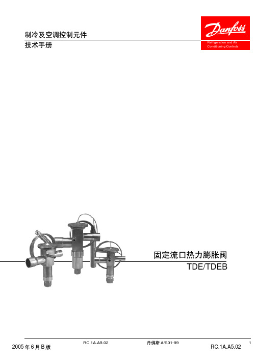
丹佛斯Danfoss-TD TDEB膨胀阀 样本
!"#$%&'( !"#$%&'()*+
! SS OS SH SS
9 !"# !"# Qmax.
DANFOSS ABBN202.10
OS
!" min.20%
SS
4K !"#$%&' 4K
Qnam.
OS
4K !" 4K !"# !" !"#$%&'() !" 8K ! "#$%& ! K SS SH OS !"#$
12
13
14
15
16
17
TDEX19 TDEX16 TDEX12.5 TDEX11 TDEX8
!(bar)
6
RC.1A.A5.02
A/S01-99
DANFOSS A68N192.11.11
1
2
3
4
1
2
3
4
7 8
!
8. !"#$%TDEB8-19
!" TDE
!"#$%
TDEB
!
!"#$(K)
1 0.8 0.6 0.4 0.2 0 0.2 0.4 0.6 0.8 1 18 10 11 12 13 14 15 16 17 19 20 21 22 23 24 25
1
15 /+68 F
te=+20
R22 R407C R134a
1
Pe=100 psig/6.9 bar Pe=95 psig/6.6 bar Pe=55 psig/5 bar ! !"#$ !"#$%& ,
Danfoss 多压力放行阀值用户手册说明书
Revised 11/01/85AX437060129637en-000101Multi-Pressure Relief ValvesCG-(H)-06-*(V)-(P)*DG(L)-0*-(H)-*-20CG-(H)-10-*(V)-(P)*DG(L)-0*-(H)-*-20Parts Manualby Danfoss#3DG4S4-010N-*-51Pilot Valve(Refer to I-3471-S for parts information)DG4S4-010A-*-50Pilot Valve(Refer to I-3478-S for parts information)Model CodeFor satisfactory service life of these components in industrial applications,use full flow filtrationto provide fluid which meets ISO cleanliness code18/15or cleaner.Printed in U.S.A.Danfoss Power Solutions is a global manufacturer and supplier of high-quality hydraulic and electric components.We specialize in providing state-of-the-art technology and solutions that excel in the harsh operating conditions of the mobile off-highway market as well as the marine sector.Building on our extensive applications expertise,we work closely with you to ensure exceptional performance for a broad range of applications.We help you and other customers around the world speed up system development,reduce costs and bring vehicles and vessels to market faster.Danfoss Power Solutions –your strongest partner in mobile hydraulics and mobile electrification.Go to for further product information.We offer you expert worldwide support for ensuring the best possible solutions foroutstanding performance.And with an extensive network of Global Service Partners,we also provide you with comprehensive global service for all of our components.Local address:DanfossPower Solutions GmbH &Co.OHG Krokamp 35D-24539Neumünster,Germany Phone:+4943218710DanfossPower Solutions ApS Nordborgvej 81DK-6430Nordborg,Denmark Phone:+4574882222DanfossPower Solutions (US)Company 2800East 13th Street Ames,IA 50010,USA Phone:+15152396000DanfossPower Solutions Trading (Shanghai)Co.,Ltd.Building #22,No.1000Jin Hai Rd Jin Qiao,Pudong New District Shanghai,China 201206Phone:+862120806201Danfoss can accept no responsibility for possible errors in catalogues,brochures and other printed material.Danfoss reserves the right to alter its products without notice.This also applies to products already on order provided that such alterations can be made without subsequent changes being necessary in specifications already agreed.All trademarks in this material are property of the respective companies.Danfoss and the Danfoss logotype are trademarks of Danfoss A/S.All rights reserved.Products we offer:•Cartridge valves •DCV directional control valves•Electric converters •Electric machines •Electric motors •Gear motors •Gear pumps •Hydraulic integrated circuits (HICs)•Hydrostatic motors •Hydrostatic pumps •Orbital motors •PLUS+1®controllers •PLUS+1®displays •PLUS+1®joysticks and pedals•PLUS+1®operator interfaces•PLUS+1®sensors •PLUS+1®software •PLUS+1®software services,support and training •Position controls and sensors•PVG proportional valves •Steering components and systems •TelematicsHydro-Gear Daikin-Sauer-Danfoss。
丹弗斯PVG32系列比例多路阀样本
丹弗斯PVG32系列比例多路阀样本丹弗斯(Danfoss)PVG32系列比例多路阀是一种高性能的液压控制阀,广泛应用于工程机械、农业机械、航空机械等领域。
PVG32系列比例多路阀是基于丹弗斯先进的闭环控制技术,采用比例电磁阀和先进的电子控制器,具有精确的控制能力和高可靠性。
本文将详细介绍PVG32系列比例多路阀的特点、应用领域和技术指标。
PVG32系列比例多路阀的特点:1.高精度控制:PVG32系列比例多路阀采用先进的比例电磁阀和电子控制器,可以实现精确而稳定的液压控制,满足工程机械和其他应用中对精度要求高的场景。
2.良好的可调性:PVG32系列比例多路阀具有广泛的调节范围,可以实现多种不同的流量和压力控制需求。
通过电子控制器的参数调整,可以轻松实现控制参数的改变。
3.高性能比例电磁阀:PVG32系列比例多路阀采用了先进的比例电磁阀技术,具有快速的响应速度和稳定的控制特性,能够快速实现液压控制信号的转换。
4.多种控制方式:PVG32系列比例多路阀支持多种不同的控制模式,包括手动操作、电流控制和压力控制等,满足不同工作场景的需求。
5.高可靠性:PVG32系列比例多路阀采用先进的电子控制技术和优质的材料制造,具有较高的可靠性和耐用性,适用于各种恶劣的工作环境。
PVG32系列比例多路阀的应用领域:1.工程机械:PVG32系列比例多路阀广泛应用于各种工程机械设备,如挖掘机、装载机、推土机等。
可以实现对液压系统的精确控制,提高机械设备的操作性能和效率。
2.农业机械:PVG32系列比例多路阀也适用于农业机械领域,如拖拉机、农用挖掘机等。
可以实现对农业机械设备的液压系统进行精确控制,提高农机设备的工作效率和稳定性。
3.航空机械:PVG32系列比例多路阀还可以用于航空机械领域,如飞机起落架、缝翼系统等。
可以实现对航空机械设备的液压系统进行精确控制,提高航空机械设备的安全性和可靠性。
PVG32系列比例多路阀的技术指标:1. 工作压力:最高工作压力为350 bar。
丹佛斯比例阀
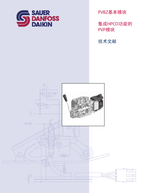
PVBZ基本模块技术文献版本修订历史目录概述 (3)剖视图 (4)功能 (5)技术参数 (6)PVP,泵侧模块-带T0口 (7)PVBZ,工作模块-带T0口 (8)PVB,工作模块-带T0口 (8)PVBZ,标准阀芯 (9)标准 FC- PVBZ阀芯 (电气和机械驱动) (10)标准 PVBZ悬浮阀芯 (电子驱动) (10)PVEH-F电气驱动 (10)PVST, 后端盖 (10)液压原理图 (11)驱动元件 (12)尺寸 (13)订购说明 PVBZ (14)订购说明 HPCO (15)© 2010 Sauer-Danfoss. 版权所有。
萨澳-丹佛斯对目录,说明书和其它出版物中可能存在的错误不负任何责任。
萨澳-丹佛斯有权不预先通知就更改其产品。
这同时也适用于已订购产品,尽管此类更改随后没有任何已认同的说明书中认为是必要的变化。
此资料中的所有商标都归属各自公司。
Sauer-Danfoss和Sauer-Danfoss标志为萨澳-丹佛斯集团商标。
2L1010371 • Rev CA • Jan 2010PVBZ基本模块技术文献PVBZ集成HPCO的PVP PVBZ模块是带有集成液控单向阀的工作模块。
PVBZ模块是为将集成了液控单向阀工作油口的泄露降到最低(低于1 cm3 [0.06 in3]每分钟)的应用而研发的。
PVBZ模块只能与本技术文献中提到的PVB工作模块和PVP泵侧模块结合使用,具有以下特征:• 集成低内泄液控单向阀• 集成热力安全阀• 标准 4/3(三位四通)阀芯• 4/4(四位四通)浮动阀芯• 阀芯可互换PVBZ(带独立回油口T0的PVB)模块是集成HPCO功能的PVG 32。
HPCO功能引导PVG 32阀组中多余的泵流通过HPCO口流到其它地方,如换向阀。
集成HPCO功能的新的PVP泵侧模块只能与本技术文献中提到的PVB、PVBZ和PVST模块配合使用,它具有以下特征:• HPCO功能• 优先保证PVG 32需要的流量• 节省油管概述3 L1010371 • Rev CA • Jan 2010PVBZ基本模块技术文献剖视图剖视图1 溢流阀2 先导油路减压阀3 压力表连接口4 堵头,开芯5 节流口,闭芯6 压力调节阀芯7 堵头,闭芯8 LS 连接口9 T0 连接口10 堵头 - 若T0内置,则移除 (仅157B5130,157B5131, 157B5330 和157B5331 )11 LS 信号12 POC先导阀13 梭阀14 液控单向阀, POC15 主阀芯16 压力补偿器17 梭针18 A和B口的最大油量调节螺钉19 PVE的先导油源20 独立回油口(T0)V310138.A4L1010371 • Rev CA • Jan 2010PVBZ基本模块技术文献功能功能当主阀芯(15)处于中位时,液控单向阀(POC)在弹簧力和工作压力的共同作用下保持关闭,工作压力经过阻尼孔作用于POC(14)的弹簧侧。
PVG32比例阀
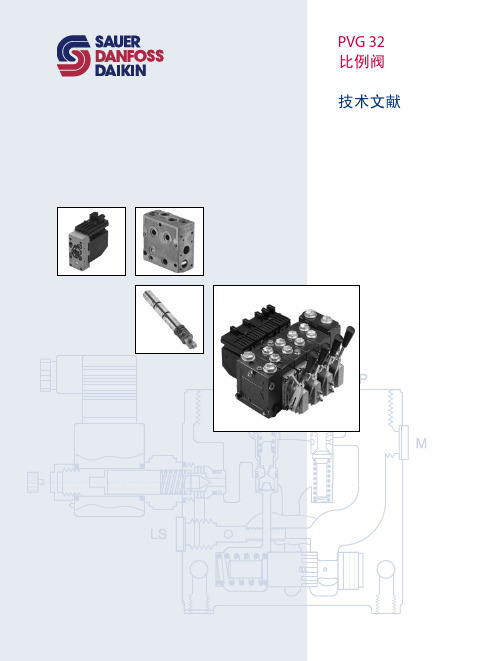
DFP32多路换向阀是我公司具有独创意识的整体式多路阀该
DFP 32 多路阀
概述:
DFP32多路换向阀是我公司具有独创意识的整体式多路阀。
该阀为整体式结构,油路为串并联形式,操纵方式为手动滑阀式,也可为液控机电液控。
该阀各工作油口可设置叠加式结构的过载阀与补油阀,其位置可根据用户要求灵活组合。
该阀具有压力高、流量大、压力损失小、微动性好、附加阀齐全、操纵力小、结构紧凑、工作可靠、维修方便等特点。
适用于装载机,推土机等大中型工程机械的液压系统中,以实现多个工作机构的集中工作。
型号说明:
DFP *32
①②③
①组合多路阀
②阀杆的组合数
③公称通径
性能参数
机能符号
外形及连接尺寸
使用注意事项:
使用介质:
1. 推荐夏季选用L-HM46或相近粘度的液压油,冬季选用L-HM32或接近粘度的液压油。
2. 工作油温范围:-20~80℃。
系统清洁度直接影响元件的可靠性。
加油前,油箱,管路应充分清洗,泵或马达所在液压系统应有过滤装置,其精度小于25μm
阀油口结合面严禁磕碰,保证结合面、接头严格密封。
3.安装外操纵机构时,应保证滑阀不受侧向力,从而使滑阀运转灵活,无卡滞现象。
4.正确安装各油口,严禁污物进入。
5.本公司售出的液压阀中之安全阀的额定压力,在出厂前已调定好,严禁随意调定。
PSL 和PSV 型负载敏感式比例多路换向阀[1]
![PSL 和PSV 型负载敏感式比例多路换向阀[1]](https://img.taocdn.com/s3/m/b0279ea6f524ccbff1218445.png)
ZPL32 中间过度板可以将 3 规格产品(见样本 D7700-3)和 2 规格直接连接
D7700-2 第 6 页
3.1.4 连接块用的附加元件
订货实例: PSL 3.1Z /380-2-…-E1-G24 PSV3S. 1Z /350-2-…-E1-G24
表 10:用工具调节的主要压力限压阀.松开锁紧螺母以后可以从 50bar 调节到 420bar(机能图 见 3.11 后 3.1.2 节).
联接板
附备注 C:1993 年由 HAWE Hydraulik 在 D-81673 Munchen 研制 没有明确的授权,不得翻印,散布和利用本资料,以及交流其内容.违规者应承担赔偿损失的责任.在授予专利权或使用 新型权时,保留一切权利.
D7700-2 第 2 页
2. 型号代码及说明
订货示例: (另一个示例可参阅第 6 节)
表 2:附加元件的代码(说明与注解 7.1.a 节) 代码 说明 无代码 标准型(集成着节流阀,单向阀,预压阀的组合,预压力约 25bar) G 单向节流阀(无顺序阀),具有增强的节流效果 H 用于提高循环压力的 3 通流量调节阀的代码(见 4.2 节),在其它方面与标 准型的机能相同,例如使用大量大流量的滑阀(表 15 的代码 5)
E2
类似 E1,具有附加接口 Y,以便与另一个分别布置的 PSV 型阀的 LS 接口相连(顺序相连的阀的总数最多
为 12,见 7.1.f 节的说明)
E4
类似 E1,然而没有 T 接口,控制油从内部回油,最大压力为 10bar!
E5
类似 E2,然而没有 T 接口(如同 E4)
E17..E20
各种变形,见 3.1.5 节表 11
E17..E20UNF 类似 E17 或 E20,然而接口螺纹为符合 SAE J514 的 SAE-10(接口尺寸见 5.2 节)
DANFOSS-PVG100阀组
技术文献
概述 PVG 100 比例阀 技术文献 目录
概述 ................................................................................................................................................................... 4 阀组系统...................................................................................................................................................... 4 PVG 100 属性概述.................................................................................................................................... 4 PVP, 泵侧模块 ............................................................................................................................................ 4 PVB,工作模块............................................................................................................................................. 4 驱动模块...................................................................................................................................................... 4
丹佛斯多路阀
2
11048997 • Jun 2008
PVE(第四代) 技术文献 功能
功能
Sauer-Danfoss 的电液控制模块(PVE),将电子元件、传感器和驱动器集成为一个独立 单元,然后直接和比例阀的阀体相连。
闭环控制 集成式反馈传感器通过检测阀芯的运动产生反馈信号。根据反馈信号和输入信号对 比所得的偏差,通过一个电磁阀桥来控制主阀芯的运动方向、速度和位置。集成式 电子元件,可以补偿阀芯压力、内部泄漏、油液粘度变化、先导压力等所带来的影 响。这样可以保证系统的低迟滞和高精度。同时这些电子元件也为系统提供了内置 的安全装置,如故障监控装置、方向指示灯和LED显示灯。
新产品的设计开发由市场和客户需求决定。Sauer-Danfoss 公司对产品研发的投入促 进了产品的发展,从而维持和扩大了我们在电液控制阀领域内的市场领先地位。
用在PVE(第四代)上的技术,是基于成熟的电控原理的。这些原理来自于诸如汽车 工业领域以及我们在行走液压行业内对电控阀的长期应用经验。PVE(第四代)不仅 延续了PVE(第二代) 和PVE(第三代)所体现的高质量和高可靠性,而且在此基础 上对PVE模块进行了规范化改进 – 如环境保护因素。
11048997 • Jun 2008
比例驱动
PVE(第四代) 技术文献 电气驱动
PVES, 超高比例性能 PVES 推荐用在对迟滞和精度要求都 非常高的控制系统。
更多的技术参数请参考 PVEH
• Hirschmann, Deutsch 或 AMP 接头
液压原理图
PVEO
PVEO-R
12 KΩ 7 (3.5) W
8
11048997 • Jun 2008
PVE(第四代) 技术文献 技术参数
基于BTN8962TA的PVG32比例阀控制技术
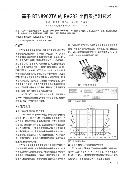
0 引言PVG32电控比例阀是阀内比例电磁铁根据输入的PWM 电压信号产生相应动作,使工作阀芯产生位移,阀口尺寸发生改变并以此完成与输入电压成比例的压力、流量输出的元件。
由于PVG32电控比例阀具有模块化设计、结构紧凑、组合形式多样、高集成性、控制精度高、安装使用灵活等优点,其使用越来越广泛,大量用于液压控制中。
SAUER-DANFOSS设计生产的PVG32电控比例阀以往电控驱动控制功能实现均使用该公司配套设计的控制器。
SAUER-DANFOSS控制器整机硬件含CPU均为全进口器件,硬件电路的实现方式、运行机理、故障维护等均无法掌握,其软件采用类PLC语言,利用进口软件开发工具开发的驱动层软件、协议层软件和应用层软件等,软件均运行在非开源环境下,因此,软件控制底层亦不能完全掌握。
针对上述PVG32电控比例阀的控制需求,本项目研究了PVG32电控比例阀控制技术的设计和验证方法,通过试验测试,验证了控制技术的有效性。
1 原理与设计■1�1 PVG32比例阀电控工作原理SAUER-DANFOSS的PVG32电控比例阀集成有电液驱动模块(PVE),将电子元件、传感器和驱动器集成为一个独立单元,然后直接和比例阀的阀体相连。
所有的比例驱动模块都配有集成的反馈传感器,反馈传感器通过检测阀芯的运动产生反馈信号,根据反馈信号和输入信号对比所得的偏差,执行机构通过一个电磁阀桥来控制主阀芯的运动方向、速度和位置。
集成式电子元件,可以补偿阀芯压力、内部泄露、油液粘度变化、先导压力等所带来的影响。
这样可以保证系统的低迟滞和高精度。
PVG32比例阀电控工作原理为输入信号决定了推动主阀芯的先导压力等级,反馈传感器检测主阀芯的位置,产生一个电控模块可识别的反馈信号。
电控系统通过输入信号和反馈信号之间的偏差来驱动电磁阀,进而改变先导压力,驱动主阀芯到正确的位置。
电液驱动模块具备集成脉宽调制功能,PVEA/PVEH/PVES对主阀芯位置基于脉宽调制原理来控制,一旦主阀芯到达所需位置,调制停止,阀芯位置被锁定。
萨澳(SAUER DANFOSS)全系列产品介绍

变量泵 (45系列)
节流阀 (SC13)
过滤器 齿轮泵
比例阀组 (PVG) 和 HIC
终端设备 (DP200)
逆变器
-
+
手柄 (JS1000)
油箱
叉车工作系统
比例阀组 (PVG)
挖掘机构
变量泵 (45系列)
装载机构 控制器 (PLUS+1™)
手柄 (JS6000)
CAN 总线
两头忙工作系统
4
设计阶段
Valves
阀
久经市场考验的成熟产品,质量可靠,模块化 设计理念,这些使得我们的阀类产品可以用在 几乎任何场合。我们提供负载敏感、电控、以 及与负载无关的比例阀。采用我们的阀类产 品,你可以用多种控制方式满足最苛刻的使用 要求,且机器操作性能平稳,经久耐用。
Steering Components and Systems
齿轮泵
比例阀组 (PVG)
转角 传感器
控制手柄 (Prof1)
转角 传感器
控制器 (PLUS+1™)
电子方向盘
GPS 接收器
SASA
控制器 (PLUS+1™)
转向器 (OSPE) 至驱动系统 补油回路
梭阀
转向 优先阀 (OLS)
转向轮 角度 传感器
变量泵 (45系列)
压路机转向系统
联合收割机转向系统
TM
7
Hydrostatics
静液压产品
对于非公路设备,萨澳-丹佛斯-大金从 元件和系统两个方面,提供传动解决方 案,我们的产品规格齐全,能够用于单 边和双边推进驱动以及闭式回路辅助传 动中大,中,小功率的应用。对于中,小 功率的车辆,例如高空作业车,滑移装 载机,小压路机,割草机,以及对于大 功率车辆,例如联合收割机,履带式车 辆,林业机械和压路机,萨澳-丹佛斯大金都能提供合适的静液压传动方案。
- 1、下载文档前请自行甄别文档内容的完整性,平台不提供额外的编辑、内容补充、找答案等附加服务。
- 2、"仅部分预览"的文档,不可在线预览部分如存在完整性等问题,可反馈申请退款(可完整预览的文档不适用该条件!)。
- 3、如文档侵犯您的权益,请联系客服反馈,我们会尽快为您处理(人工客服工作时间:9:00-18:30)。
Revision history Table of revisionsTechnical InformationPVG 32 Proportional Valve Group2 | © Danfoss | August 2017520L0344 | BC00000038en-US0802General descriptionFeatures of PVG 32...........................................................................................................................................................................5PVG modules .....................................................................................................................................................................................5PVP, pump side modules..........................................................................................................................................................5PVB, basic modules.....................................................................................................................................................................5Actuation modules.....................................................................................................................................................................6Remote control units ......................................................................................................................................................................6PVG 32 with open center PVP......................................................................................................................................................7PVG 32 with closed center PVP....................................................................................................................................................8PVG 32 sectional view.....................................................................................................................................................................9Load sensing for variable displacement pump supply.......................................................................................................9Safety in applicationControl system example..............................................................................................................................................................12Examples of wiring block diagram.....................................................................................................................................14FunctionLoad sensing controls...................................................................................................................................................................16LS control with bleed orifice (do not use with PVG valves).......................................................................................16Integral PC function.................................................................................................................................................................16Load sensing system characteristics:.................................................................................................................................16Remote pressure compensated controls..............................................................................................................................16Remote pressure compensated system characteristics:............................................................................................17Typical applications for remote pressure compensated systems:..........................................................................17PVG 32 main spool with pressure compensated control................................................................................................17Pressure compensated system characteristics..............................................................................................................18Typical applications for pressure compensated systems...........................................................................................18PVPC adapter for external pilot oil supply............................................................................................................................18PVPC with check valve for open center PVP...................................................................................................................18PVPC without check valve for open or closed center PVP.........................................................................................19PVMR, friction detent....................................................................................................................................................................21PVMF, mechanical float position lock.....................................................................................................................................21PVBS, main spools for flow control (standard)....................................................................................................................21PVBS, main spools for flow control (linear characteristic)...............................................................................................21PVBS, main spools for pressure control.................................................................................................................................22Background.................................................................................................................................................................................22Principle.......................................................................................................................................................................................22Application..................................................................................................................................................................................23Sizing.............................................................................................................................................................................................23Limitation....................................................................................................................................................................................24PVPX, electrical LS unloading valve.........................................................................................................................................24PVG 32 technical dataPVH, hydraulic actuation.............................................................................................................................................................26PVM, mechanical actuation........................................................................................................................................................26PVE, electrical actuation..............................................................................................................................................................26PVPX, electrical LS unloading valve.........................................................................................................................................29Electrical actuationElectrical control of PVG..............................................................................................................................................................30Closed loop control.......................................................................................................................................................................31PVEO...................................................................................................................................................................................................32PVEM...................................................................................................................................................................................................32PVEA, PVEH, PVES, PVEU..............................................................................................................................................................33PVEP....................................................................................................................................................................................................33PVED-CC and PVED-CX.................................................................................................................................................................33PVHC...................................................................................................................................................................................................34Technical characteristicsGeneral...............................................................................................................................................................................................36PVP, pump side module.. (36)Technical InformationPVG 32 Proportional Valve GroupContents© Danfoss | August 2017520L0344 | BC00000038en-US0802 | 3PVB, basic modules oil flow characteristics..........................................................................................................................36Pressure-compensated PVB, open center PVP ..............................................................................................................37PVB without pressure compensation, open center PVP.............................................................................................38PVB without pressure compensation, closed center PVP..........................................................................................39PVLP, shock and PVLA, suction valves...............................................................................................................................41Pressure build-up for pressure controlled spools.........................................................................................................41Pressure control spool flow characteristics..........................................................................................................................41Examples of how to use the characteristics for pressure control spools...................................................................42Characteristics for float position main spools (43)Hydraulic systemsManually actuated PVG 32 – fixed displ. pump..................................................................................................................45Electrically actuated PVG 32 – variable displ. pump.........................................................................................................46Other operating conditionsOil.........................................................................................................................................................................................................47Particle content, degree of contamination...........................................................................................................................47Filtration............................................................................................................................................................................................47DimensionsPVM, control lever positions......................................................................................................................................................50Surface treatment.. (51)Modules symbols, description and code numbersPVP, pump side modules.............................................................................................................................................................52PVB, basic modules........................................................................................................................................................................54PVLA, suction valve (fitted in PVB)...........................................................................................................................................56PVLP, shock and suction valve (fitted in PVB)......................................................................................................................56PVM, mechanical actuation........................................................................................................................................................57PVH, hydraulic actuation.............................................................................................................................................................58PVS, end plate..................................................................................................................................................................................58PVAS, assembly kit.........................................................................................................................................................................58PVPX, electrical LS unloaded valve..........................................................................................................................................58PVPC, plug for external pilot oil supply..................................................................................................................................59Module selection chartStandard FC spools........................................................................................................................................................................60Standard FC spools, hydraulic actuation...............................................................................................................................61FC spools for mechanical float position, PVMF...................................................................................................................61FC spools for friction detent, PVMR.........................................................................................................................................62FC spools with linear flow characteristic ..............................................................................................................................62Standard PC spools .......................................................................................................................................................................63Standard PC spools, hydraulic actuation...............................................................................................................................64PVB, basic valves.............................................................................................................................................................................65PVP, pump side module..............................................................................................................................................................66PVE, electrical actuation..............................................................................................................................................................68Order specificationStandard and option assembly.................................................................................................................................................70Reordering........................................................................................................................................................................................70Pressure setting limits..................................................................................................................................................................70PVG 32 specification sheet (72)Technical InformationPVG 32 Proportional Valve GroupContents4 | © Danfoss | August 2017520L0344 | BC00000038en-US0802PVG 32 is a hydraulic load sensing valve designed to give maximum flexibility. From a simple load sensing directional valve, to an advanced electrically controlled load-independent proportional valve.The PVG 32 modular system makes it possible to build up a valve group to meet requirements precisely.The compact external dimensions of the valve remain unchanged whatever combination is specified.Features of PVG 32•Load-independent flow control:‒Oil flow to an individual function is independent of the load pressure of this function‒Oil flow to one function is independent of the load pressure of other functions •Good regulation characteristics •Energy-saving•Up to 12 basic modules per valve group •Several types of connection threads •Low weight•Compact design and installationPVG modulesPVP, pump side modules•Built-in pressure relief valve •Pressure gauge connection•Versions:‒Open center version for systems with fixed displacement pumps‒Closed center version for systems with variable displacement pumps ‒Pilot oil supply for electrical actuator built into the pump side module ‒Pilot oil supply for hydraulic actuation built into the pump side module ‒Versions prepared for electrical LS unloading valve PVPXPVB, basic modules•Interchangeable spools•Depending on requirements the basic module can be supplied with:‒Integrated pressure compensator in channel P‒Load holding check valve in channel P ‒Shock/suction valves for A and B portsTechnical InformationPVG 32 Proportional Valve GroupGeneral description© Danfoss | August 2017520L0344 | BC00000038en-US0802 | 5‒LS pressure limiting valves individually adjustable for ports A and B ‒Different interchangeable spool variants‒All versions suitable for mechanical, hydraulic and electrical actuationActuation modulesThe basic module is always fitted with mechanical actuator PVM and PVMD, which can be combined with the following as required:•Electrical actuator (11 - 32 V ===):‒PVES – proportional, Super‒PVEH – proportional, High performance ‒PVEH-F – proportional high performance, Float ‒PVEA – proportional low hysteresis ‒PVEM – proportional, Medium performance ‒PVEO – ON/OFF‒PVEH-U/PVES-U – proportional, voltage control, 0-10 V ‒PVED-CC – Digital CAN controlled J1939/ISOBUS ‒PVED-CX – Digital CAN controlled CANopen X-tra safety ‒PVEP – PWM voltage controlled (11-32 V)‒PVHC – High Current actuator for PVG•PVMR, cover for Mechanical detent •PVMF, cover for Mechanical Float •PVH, cover for Hydraulic actuationRemote control units•Electrical remote control units:‒PVRE, PVRET ‒PVREL ‒PVRES ‒Prof 1‒Prof 1 CIP ‒JS120‒JS1000 Ball grip ‒JS1000 PRO grip ‒JS2000‒JS6000‒JS7000•Hydraulic remote control unit: PVRHHTechnical InformationPVG 32 Proportional Valve GroupGeneral description6 | © Danfoss | August 2017520L0344 | BC00000038en-US0802Electrical and hydraulic remote control unitsPVRE, electrical control unit, 162F…PVREL, electrical control unit, 155U…PVRH, hydraulic control unit, 155N…155N0003 155N0001155N0004 155N0005 155N0002PVG 32 with open center PVPPVG 32 with open center PVP (fixed displacement pump) and PVB with flow control spool.When the pump is started and the main spools in the individual basic modules (11) are in the neutral position, oil flows from the pump, through connection P, across the pressure adjustment spool (6) to tank.The oil flow led across the pressure adjustment spool determines the pump pressure (stand-by pressure).When one or more of the main spools are actuated, the highest load pressure is fed through the shuttle valve circuit (10) to the spring chamber behind the pressure adjustment spool (6), and completely or partially closes the connection to tank to maintain pump pressure.Pump pressure is applied to the right-hand side of the pressure adjustment spool (6).The pressure relief valve (1) will open should the load pressure exceed the set value, diverting pump flow back to tank.In a pressure-compensated basic module the compensator (14) maintains a constant pressure drop across the main spool – both when the load changes and when a module with a higher load pressure is actuated.With a non pressure-compensated basic module incorporating a load drop check valve (18) in channel P,the check valve prevents return oil flow.The basic module can be supplied without the load drop check valve in channel P for functions with over-center valves.The shock valves PVLP (13) with fixed setting and the suction valves PVLA (17) on ports A and B are used for the protection of the individual working function against overload and/or cavitation.Technical InformationPVG 32 Proportional Valve GroupGeneral description© Danfoss | August 2017520L0344 | BC00000038en-US0802 | 7An adjustable LS pressure limiting valve (12) can be built into the A and B ports of pressure-compensated basic modules to limit the pressure from the individual working functions. Please see the sectional drawing PVG 32 sectional view on page 9 below for better understanding of this example.The LS pressure limiting valves save energy compared with the shock valves PVLP:•with PVLP all the oil flow to the working function will be led across the combined shock and suctionvalves to tank if the pressure exceeds the fixed setting.•with LS pressure limiting valves an oil flow of about 2 l/min [0.5 US gal/min] will be led across the LSpressure limiting valve to tank if the pressure exceeds the valve setting.PVG 32 with closed center PVPPVG 32 with closed center PVP (variable displacement pump) and PVB with flow control spool.In the closed center version of PVP an orifice (5) and a plug (7) have been fitted instead of the plug (4).This means that the pressure adjustment spool (6) will only open to tank when the pressure in channel P exceeds the set value of the pressure relief valve (1).In load sensing systems the load pressure is led to the pump control via the LS connection (8).In the neutral position the pump load sense control sets the displacement so that leakage in the system is compensated, to maintain the set stand-by pressure.When a main spool is actuated the pump load sense control will adjust the displacement so that the set differential pressure (margin) between P and LS is maintained.The pressure relief valve (1) in PVP should be set at a pressure of approx. 30 bar [435 psi] above maximum system pressure (set on the pump or external pressure relief valve).Technical InformationPVG 32 Proportional Valve GroupGeneral description8 | © Danfoss | August 2017520L0344 | BC00000038en-US0802PVG 32 sectional viewPVPPVBPVB1. Pressure relief valve11. Main spool2. Pressure reduction valve for pilot oil supply 12. LS pressure limiting valve3. Pressure gauge connection 13. Shock and suction valve, PVLP4. Plug, open center 14. Pressure compensator5. Orifice, closed center 15. LS connection, port A6. Pressure adjustment spool 16. LS connection, port B7. Plug, closed center 17. Suction valve, PVLA8. LS connection 18. Load drop check valve9. LS signal 19. Pilot oil supply for PVE10. Shuttle valve20. Maximum oil flow adjustment screws for A/B portsLoad sensing for variable displacement pump supplyThe pump receives fluid directly from the reservoir through the inlet line. A screen in the inlet lineprotects the pump from large contaminants.Technical InformationPVG 32 Proportional Valve GroupGeneral description© Danfoss | August 2017520L0344 | BC00000038en-US0802 | 9The pump outlet feeds directional control valves such as PVG-32, hydraulic integrated circuits (HIC), and other types of control valves.The PVG valve directs and controls pump flow to cylinders, motors and other work functions. A heat exchanger cools the fluid returning from the valve. A filter cleans the fluid before it returns to the reservoir.Flow in the circuit determines the speed of the actuators. The position of the PVG valve spool determines the flow demand. A hydraulic pressure signal (LS signal) communicates demand to the pump control.The pump control monitors the pressure differential between pump outlet and the LS signal, and regulates servo pressure to control the swashplate angle. Swashplate angle determines pump flow.Actuator load determines system pressure. The pump control monitors system pressure and will decrease the swashplate angle to reduce flow if system pressure reaches the pump control setting.A secondary system relief valve in the PVG valve acts as a back-up to control system pressure.Pictorial circuit diagramTechnical InformationPVG 32 Proportional Valve GroupGeneral description10 | © Danfoss | August 2017520L0344 | BC00000038en-US0802Safety in applicationAll types of control valves (incl. proportional valves) can fail, thus the necessary protection against theserious consequences of function failure should always be built into the system. For each application anassessment should be made for the consequences of pressure failure and uncontrolled or blockedmovements. To determine the degree of protection that is required to be built into the application,system tools such an FMEA (Failure Mode and Effect Analysis) and Hazard and Risk Analysis can be used.FMEA – IEC EN 61508FMEA (Failure Mode and Effect Analysis) is a tool used for analyzing potential risks. This analyticaltechnique is utilized to define, identify, and prioritize the elimination or reduction of known and/orpotential failures from a given system before it is released for production. Please refer to the standard IECFMEA 61508.Hazard and risk analysis ISO 12100-1/14121This analysis is a tool used in new applications as it will indicate whether there are special safetyconsiderations to be met according to the machine directives EN 13849. Dependent on the determinedlevels conformity this analysis will detirmine if any extra requirements for the product design,development process, production process or maintenance, example the complete product life cycle.W WarningAll brands and all types of directional control or proportional valves, which are used in many differentoperation conditions and applications, can fail and cause serious damage.Analyze all aspects of the application. The machine builder/system integrator alone is responsible formaking the final selection of the products and assuring that all performance, safety and warningrequirements of the application are met. The process of choosing the control system and safety levels isgoverned by the machine directives EN 13849 (Safety related requirements for control systems).Control system exampleExample of a control system for manlift using PVE Fault monitoring input signals and signals from external sensors to ensure the PLUS+1® maincontrollers correct function of the manlift.Safety in applicationElectrical block diagram for the above illustrationWWarningIt is the responsibility of the equipment manufacturer that the control system incorporated in the machine is declared as being in conformity with the relevant machine directives.PVG 32 – mainly used in system with fixed displacement pumps:•PVSK, commonly used in crane application - full flow dump •PVPX, LS dump to tankPVG 100 – alternative LS dump or pilot supply disconnect:•PVPP, pilot oil supply shut off•External cartridge valve connecting LS pressure or main pressure to tank PVG 120 – pump disconnect / block for variable pumps:Safety in applicationSafety in application•PVPE, full flow dump for the PVG 120•External cartridge valve connecting LS pressure to tankExamples of wiring block diagramExample of a typical wiring block diagram using PVEH with neutral power off switch and fault monitoringoutput for hydraulic deactivation.A– Emergency stop / man present switchB– PVE Fault monitoring signalsC– Neutral signal detection.D– Hydraulic deactivationSystem Control Logic e.g. PLUS+1® for signal monitoring and triggering signal for deactivation of thehydraulic system.W WarningIt is the responsibility of the equipment manufacturer that the control system incorporated in themachine is declared as being in conformity with the relevant machine directives.。