喷枪使用说明书
CARLISLE ST1多组件空气喷枪 手册说明书

ST1 多组件空气喷枪快速入门手册
阅读本手册 请在使用本产品前,阅读并理解使用手册中提 供的安全信息、操作信息和维护信息。
操作人员培训 设备的操作只能由经过培训的人员 进行。
卸压操作 始终按照设备使用手册中卸压程序操 作。
入门设置
1. 关闭A侧和B侧的截止阀。
B
A
2. 将A侧(异氰酸酯)和B侧(树脂)软 管和管路块连接。
1
19 34
单独喷嘴 (包含插头)
10
52 53 54
50
40
侧面密封套组件 336375 (序号 5) & 336376 (序号 6)
序号 零件号码
零件名称
数量
50
NA 侧面密封套外壳
1
10
336415 外壳O形圈 (10件)
2
52
336378 侧面密封弹簧
1
53
336414 侧面密封O形圈 (10件)
1
336379 聚合物侧面密封件
54
1
聚合物侧面密封件
336410
注意:可选配不锈钢侧面密封件(零件号码பைடு நூலகம்336381)
61 60
10
零件号码
规格尺寸
336452
00 (.052)
336453
01 (.060)
336454
15 (.064)
336455
02 (.070)
336456
03 (.086)
14. 设定好压力和温度,并且喷涂泡沫达 到使用要求时,喷枪就可以开始喷涂作业 了。
10. 打开比例混合器,关于比例混合器操 作请遵循生产厂家的规定。
11. 完全打开B侧(树脂)截止阀,然后打 开A侧(异氰酸酯)截止阀。
KCI静电喷涂机使用说明书

KCI静电喷涂机使用说明书
1、枪距
喷枪口与被涂物面的距离称为枪距,枪距以300~400mm为宜。
枪距过小,喷涂压力过大,反冲力也大,容易出现涂层不均匀现象,而且喷幅(扇面宽度)小,使被涂物局部喷料过多,涂膜过厚。
枪距过大,喷涂压力损失大,涂料易散失,而且喷幅过大,使被涂物局部喷料过少,涂膜达不到厚度要求。
2、喷涂扇面角度
喷涂扇面与被涂物面要相互垂直,手工操作喷枪时,要注意每次的喷涂宽度不宜过大,否则因操作不便会引起喷涂扇面角度明显变化,造成涂层不均匀。
3、喷枪运行方向及速度:
喷枪运行的方向要始终与被涂物面平行,与喷涂扇面垂直,以保证涂层的均匀性。
喷枪运行速度要稳,以300~400mm/s为宜。
运行速度不稳,涂层厚度不均匀,运行速度过快涂层太薄,过慢涂层太厚。
JGX-502喷枪操作手册说明书
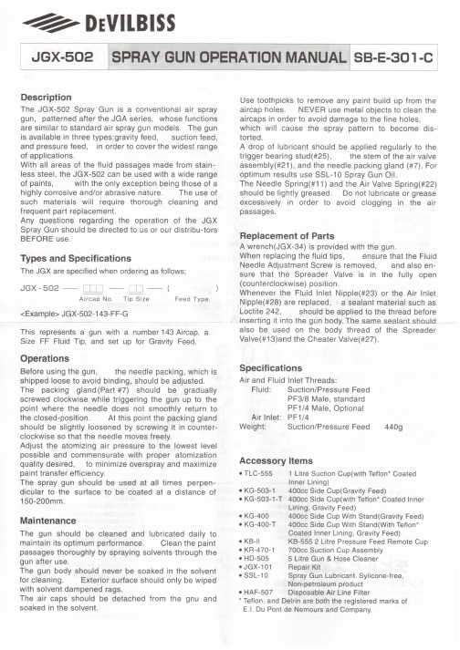
1 19*
Packing
1
3
See Chart 2 Fluid Tip
• KB-II
KB-555 2 Litre Pressure Feed Remote Cup
• KR-470-1 700cc Suction Cup Assembly
• HD-505
5 Litre Gun & Hose Cleaner
• JGX-101
Repair Kit
• SSL-10
Spray Gun Lubricant. Sylicone-free,
Notice:The fluid tip of Suction Feed gun and GY Tip (0.8m/m) is not with soft-seat.
Fluid Needles
Code
Part Number
803750
JGX-41-GX
803751
JGX-41-FX
803751
JGX-41-FX
optimum results use SSL-10 Spray Gun Oil.
The Needle Spring(#11) and the Air Valve Spring(#22) should be lightly greased. Do not lubricate or grease
excessively in order to avoid clogging in the air
maintain its optimum performance. Clean the paint
passages thoroughly by spraying solvents through the
喷枪使用说明书
喷枪使用说明书一、介绍喷枪是一种常见的喷涂设备,广泛应用于涂料施工、汽车喷漆、家具制造等行业。
本使用说明书将详细介绍如何正确使用喷枪,以确保安全和高效的操作。
二、安全注意事项在使用喷枪之前,请务必遵循以下安全注意事项:1. 仔细阅读和理解本使用说明书,并确保了解相关使用规范。
2. 在操作喷枪时,请戴上合适的防护手套、面具和安全眼镜。
3. 保持工作区域清洁,并确保有良好的通风条件。
4. 在操作喷枪之前,请检查设备的连接部件是否紧固。
5. 操作喷枪时,请确保周围没有易燃或易爆物品。
6. 当喷枪不在使用时,请关闭气源并放置在安全位置。
三、喷枪的组成部分1. 喷枪手柄:用来控制涂料喷射。
2. 喷枪嘴口:涂料从这里喷出。
3. 涂料杯:用来存放喷涂涂料。
4. 压力控制按钮:用来调节喷涂压力。
5. 涂料调节旋钮:用来调节喷涂涂料的流量和喷涂效果。
四、喷枪的操作步骤1. 准备工作:将喷枪与喷枪压缩机连接,并确保连接紧固。
同时,检查喷枪的气源和涂料杯,确保其正常工作。
2. 调节气压:根据需要,使用喷枪上的压力控制按钮调节喷枪的气压。
3. 调节喷涂效果:使用涂料调节旋钮来调节喷涂涂料的流量和喷涂效果。
根据需要,可以适当调整喷嘴口的大小。
4. 进行喷涂:将喷枪对准需要喷涂的物体,并将喷涂涂料均匀地喷在表面上。
喷涂时需保持适当的距离和速度,以确保涂料均匀覆盖整个表面。
5. 喷涂结束:完成喷涂后,关闭气源,清洁喷枪。
将没有用完的涂料倒掉,并清洗涂料杯和喷嘴口。
五、保养与维护1. 每次使用完喷枪后,都应该进行清洁和保养。
使用清洁剂和刷子清洗涂料杯和喷嘴口,确保其干净无污染。
2. 定期检查喷枪的连接部件是否紧固,是否有损坏或磨损的部件,如有需要及时更换。
3. 使用时应避免将喷枪接触到尖锐物体,以免造成损坏或划伤。
4. 喷枪不使用时,应放置在干燥通风的地方,避免阳光直射或潮湿环境,以防止生锈和损坏。
六、常见问题及解决方法1. 喷枪喷出的涂料不均匀怎么办?可以通过调节喷枪的气压和涂料流量来解决这个问题。
农业喷药器使用说明书
农业喷药器使用说明书使用说明书1. 农业喷药器概述农业喷药器是一种用于农田作物防治病虫害的设备,通过喷洒农药来保护作物的生长和产量。
本使用说明书将详细介绍农业喷药器的组成、使用方法、注意事项以及维护保养等内容。
2. 喷药器组成农业喷药器由以下几个部分组成:(1) 背负式或手持式喷药器:负责携带和操作喷药器;(2) 喷枪:连接到喷药器,负责喷洒药液;(3) 压力泵:将药液从容器中抽取出来,并提供喷药所需的压力;(4) 容器:用于储存农药溶液;(5) 控制阀:用于控制药液的流量和喷药方向等。
3. 喷药器的使用方法(1) 装载容器:将预先配制好的农药溶液倒入容器中,注意不要超过推荐的容量限制。
(2) 连接喷枪:将喷枪连接到喷药器的出液口,确保连接紧固。
(3) 调整压力:根据作物和农药的需要,调整喷药器的压力,一般推荐在标定范围内使用。
(4) 开始喷药:按下控制阀的开启按钮,持喷枪对准作物进行均匀喷洒药液。
注意保持喷洒的速度和距离一致,使药液均匀覆盖叶面。
(5) 结束喷药:当完成喷药任务后,松开控制阀的按钮,停止喷药,并稍作休息,以免过度劳累。
4. 注意事项(1) 安全使用:在操作喷药器时,务必穿戴防护服、手套、口罩等个人防护用具,避免药液接触皮肤、眼睛和口腔等。
若不慎接触,应立即用清水冲洗并就医。
(2) 选择适当的天气条件:在进行喷药作业时,应选择无风或微风的天气,在风速达到一定程度时请暂停作业,以免药液漂移造成污染。
(3) 注意喷药距离:根据农药的使用说明,确定喷药距离,保持适当的距离避免喷雾过量或不足。
(4) 药剂清洗:每次使用完毕后,应及时清洗喷药器的各个部件,以防不同农药残留对作物产生不良影响。
(5) 存放和维护:在使用完毕后,将喷药器存放在干燥通风的地方,定期检查和维护设备,保持其正常工作状态。
5. 维护保养(1) 压力泵保养:每次使用完毕后,清洗泵体和滤网,以防止杂质和农药残留导致堵塞。
定期润滑泵体的活塞以确保其灵活性和耐久性。
喷枪使用说明书
喷枪使用说明书
1、水泥窑运行时,如果喷枪未使用,请及时取出悬挂于分解炉外面,并且用套帽堵住喷枪套筒。
喷枪悬挂时请注意放置好喷枪,防止掉落,损坏喷枪氨水进口玻璃视镜,促使喷枪尾部漏氨水,影响喷枪的正常使用和现场操作人员的身体健康。
2、水泥窑未运行时,喷枪可以放置在分解炉中不取出,但是喷枪内的压缩空气必须开启,防止喷枪堵塞,影响喷枪的下一次使用;如果现场操作人员方便,尽量将喷枪取出,悬挂到适当的位置,并且用套帽堵住喷枪套筒。
3、喷枪使用过程中,轻拿轻放,保证喷枪完好,增加喷枪的使用寿命。
4、定期检查喷枪套筒是否堵塞,如果堵塞采用压缩空气反吹或者人工导通。
5、喷射系统开启前,请保证压力不要过大,以免使喷枪视镜由于压力过大而压碎,影响喷枪的正常使用。
南京西普环保科技有限公司。
pq2喷枪使用说明

pq2喷枪使用说明
1、使用前,要检查气压,采用说明书规定的气压。
2、气源必须使用干燥无尘的普通压缩空气,严禁使用氧气和任何易燃气体,以免造成意外伤害。
3、使用喷枪时用手扣压扳机,使压缩空气的通道首先开放,继而出漆嘴的通道开放。
压缩空气由管道通向喷头,此时正遇上由出漆嘴流出来的油漆,油漆即被吹散并喷到工件上,放松扳机时,出漆嘴的小孔被顶针紧密地密封,压缩空气通道也被堵住。
4、使用喷枪时用手扣压扳机,使压缩空气的通道首先开放,继而出漆嘴的通道开放。
压缩空气由管道通向喷头,此时正遇上由出漆嘴流出来的油漆,油漆即被吹散并喷到工件上,放松扳机时,出漆嘴的小孔被顶针紧密地恋封,压缩空气通道也被堵住。
5、利用喷嘴上的辅助空气通道及喷嘴的不同位置,可调得各种不同形状的漆流。
明治喷枪使用说明书

000为了能安全使用设备,本使用说明书中记载着可能导致受伤或危及生命的重要信息。
使用前请务阅读完本使用说明书,充分理解后再使用。
另外,请妥善保管本使用说明书。
●涂料有引火性,有造成火灾与爆炸的危险。
请在宽敞通风好的地方喷涂。
●香烟、点火・电气设备等可能会引火的东西一定要避开使用。
●清洗溶剂,请使用与涂料的引火点同等或以上的溶剂。
通常清洗时所使用的溶剂有发生火灾的危险, 所以,请使用引火点37.8℃以上的溶剂。
●请在喷涂作业区安装灭火器。
2.禁止使用卤代烃类溶剂。
●因化学反应,本体(铝部分)会发生裂缝、溶解。
●不适合溶剂:氯甲烷、氯乙烷、二氯甲烷、二氯乙烷、四氯化碳、三氯乙烯、1.1.1三氯乙烷等。
●特殊的涂料和稀释剂请在充分考虑是否适合后再使用。
3.接地线。
●喷枪使用接地线软管,请切实地连接接地线。
●涂装作业请务必在喷房设备及通风设备齐全的地方进行。
●在密闭的房间或者换气不足的区域喷涂,会增加发生有机溶剂中毒或引火的危险。
2.适当的服装、保护用具。
●涂装和清洗时,请务必穿着合适的服装和使用保护用具。
(眼镜、面罩G-7-04、手套)●有些涂料触及眼睛和皮肤会有害。
请确认涂料和溶剂,并在涂装和清洗时穿着合适的服装, 使用保护用具。
3.为了健康安全起见,建议使用耳塞。
●根据使用条件及作业环境,躁声值可能高达80dB(A)。
4.若喷涂作业时感到疲惫,请及时休息。
●绝对不要对着人或动物喷涂。
●会导致眼睛和皮肤发生炎症,对人体产生危险性。
2.遵守压力使用上限值。
●请不要在超过上限压力(0.69MPa)的情况下使用喷枪。
3.作业中断时释放掉压缩空气。
●在清洗、分解、保养检查之前以及作业中断时请务必释放掉压缩空气。
●喷枪内残留有压缩空气的话,会导致喷枪错误动作、溶剂飞溅,从而对人体产生危险性。
●释放掉压缩空气的方法:停止向喷枪供给压缩空气、涂料及稀释剂等,轻轻扣动扳机。
4.保养时,请勿触碰针阀和涂料喷嘴的尖端。
斯塔克 SG2, SG3 喷枪 使用说明书
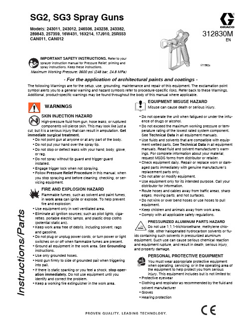
- For the application of architectural paints and coatings -The following Warnings are for the setup, use, grounding, maintenance and repair of this equipment. The exclamation point symbol alerts you to a general warning and hazard symbols refer to procedure-specific risks. Refer back to these Warnings. Additional, product-specific warnings may be found throughout the body of this manual where applicable.SKIN INJECTION HAZARDHigh-pressure fluid from gun, hose leaks, or ruptured components will pierce skin. This may look like just acut, but it is a serious injury that can result in amputation. Get immediate surgical treatment.•Do not point gun at anyone or at any part of the body.•Do not put your hand over the spray tip.•Do not stop or deflect leaks with your hand, body, glove, or rag.•Do not spray without tip guard and trigger guard installed.•Engage trigger lock when not spraying.•Follow Pressure Relief Procedure in this manual, when you stop spraying and before cleaning, checking, or ser-vicing equipment .FIRE AND EXPLOSION HAZARDFlammable fumes, such as solvent and paint fumes, in work area can ignite or explode. To help prevent fire and explosion:•Use equipment only in well ventilated area.•Eliminate all ignition sources; such as pilot lights, ciga-rettes, portable electric lamps, and plastic drop cloths (potential static arc).•Keep work area free of debris, including solvent, rags and gasoline.•Do not plug or unplug power cords, or turn power or light switches on or off when flammable fumes are present.•Ground all equipment in the work area. See Grounding instructions.•Use only grounded hoses.•Hold gun firmly to side of grounded pail when triggering into pail.•If there is static sparking or you feel a shock, stop oper-ation immediately. Do not use equipment until you identify and correct the problem.•Keep a working fire extinguisher in the work area.EQUIPMENT MISUSE HAZARDMisuse can cause death or serious injury.•Do not operate the unit when fatigued or under the influ-ence of drugs or alcohol.•Do not exceed the maximum working pressure or tem-perature rating of the lowest rated system component. See Technical Data in all equipment manuals.•Use fluids and solvents that are compatible with equip-ment wetted parts. See Technical Data in all equipment manuals. Read fluid and solvent manufacturer’s warn-ings. For complete information about your material, request MSDS forms from distributor or retailer.•Check equipment daily. Repair or replace worn or dam-aged parts immediately with genuine manufacturer’s replacement parts only.•Do not alter or modify equipment.•Use equipment only for its intended purpose. Call your distributor for information.•Route hoses and cables away from traffic areas, sharp edges, moving parts, and hot surfaces.•Do not kink or over bend hoses or use hoses to pull equipment.•Keep children and animals away from work area.•Comply with all applicable safety regulations.PRESSURIZED ALUMINUM PARTS HAZARD Do not use 1,1,1-trichloroethane, methylene chlo-ride, other halogenated hydrocarbon solvents or flu-ids containing such solvents in pressurized aluminumequipment. Such use can cause serious chemical reaction and equipment rupture, and result in death, serious injury, and property damage.PERSONAL PROTECTIVE EQUIPMENTYou must wear appropriate protective equipment when operating, servicing, or in the operating area of the equipment to help protect you from serious injury. This equipment includes but is not limited to:•Protective eyewear•Clothing and respirator as recommended by the fluid and solvent manufacturer •Gloves•Hearing protectionWARNINGS312830MI n s t r u c t i o n s /P a r t s2312830MPressure Relief ProcedureFollow this Pressure Relief Procedure whenever instructed to relieve pressure, stop spraying, check or service equipment, or install or clean spray tip.1.Turn OFF power and turn sprayer pressure control to low-est pressure setting.2.Hold gun against side of flushing pail. Trigger gun into pail to relieve pressure.If you suspect spray tip or hose is clogged or that pressure has not been fully relieved after following the steps above, VERY SLOWLY loosen tip guard retaining nut or hose end coupling to relieve pressure gradually, then loosen completely. Clear hose or tip obstruction.Gun Trigger LockTo prevent injury when the gun is not in use, always set the gun’s trigger lock if unit is being shut down or left unattended.SetupMake sure sprayer is turned off and unplugged from powersource. Refer to your sprayer instruction manual for priming and spray instructions.Connect Gun to Sprayer1.Attach supply hose to sprayer fluid outlet.2.Attach other end of supply hose to gun swivel (5). Use two wrenches (one on the swivel (5) and one on the hose), totighten all connections securely.3.Refer to sprayer instruction manual for priming instructions.Installing Tip (26) and Guard (25) on Gun1.If equipment has recently been operated, relieve pressure . Set trigger lock.ing a pencil or similar object, insert seal(24) into back of guard (25).3.Install guard (25) over end of gun (1).4.Insert tip (26) in guard (25). Tighten retaining nut.OperationSpraying1.Unlock trigger lock.2.Be sure the arrow shaped tip (26) faces forward (spray).3.Hold gun perpendicular and approximately 12-inches (30 cm) from surface. Move gun first, then pull gun trigger (3) to spray a test pattern.4.Slowly increase pump pressure until coverage is uniform and even (see sprayer instruction manual for additional information).Aligning Spray1.Relieve pressure . Set trigger lock.2.Loosen guard retaining nut.3.Align guard (25) horizontally tospray a horizontal pattern.4.Align guard (25)vertically to spray a vertical pattern.Clearing Clogs1.Relieve pressure . Set trigger lock.2.Rotate tip (26) 180°. Unlock trigger lock. Trigger gun into pail or onto ground to remove clog.3.Set trigger lock. Rotate tip (26) 180° back to spray position.CleanupFlush gun after each work shift and store in a dry location. Do not leave the gun or any parts in water or cleaning solvents.WARNINGWARNINGWARNINGTrigger LockedTrigger Unlocked(spray)ti11308aWARNINGWARNINGWARNING(4) Vertical(3) Horizontal ti11564a ti11563a312830M 3Parts1c *Kit 288817 repairs both series A and B guns.1a replaces these three components of series A.Ref.Part DescriptionQty.1288817KIT, repair, gun (includes 1a, 1b, 1c)11a SEAT, valve 11b NEEDLE, gun11c 131477NUT, lock13243639TRIGGER, repair kitincludes 10, 32, 334195495GUARD, trigger 15238817KIT, swivel1195384ADAPTER, gun inlet (SG2)16 288749FILTER, gun 1CAN085FILTER, gun 17 179733SEAL, sleeve 18195395CAP, end110115484PIN, actuator222113409RETAINER, guard 123195393HANDLE, gun (SG2)1195788HANDLE, gun (SG3, SG3-E)1195920HANDLE, gun (SG3-A)124115485O-RING12617R014HOUSING, fluid 132177538STUD, trigger 133131476NUT, lock, hex 1Replacement Warning labels, tags and cards are available at no cost.Keep these spare parts on hand to reduce down timeRef.Part Description Qty.Ref Part Description Qty 24243004Single seal TRU 1CAN004Single seal TRU1243281OneSeal ™, RAC 5 (5-pack)1246453OneSeal ™, RAC X (5-pack)117P501KIT, gasket, FFLP, LP (5-pack)125237859GUARD, TRU 1CAN001GUARD, TRU 1243161GUARD, RAC 51246215GUARD, RAC X and LP 226TRU515TIP, spray 515, TRU 1CAN515TIP, spray 515, TRU 1286515TIP, spray 515, RAC 51LTX515TIP, spray 515, RAC X 1TRU517TIP, spray 517, TRU 1CAN517TIP, spray 517, TRU 1262515TIP, spray 515, RAC 51LP519TIP, spray, 519, LP 1For complete warranty information contact your local Graco distributor, call Graco customer service:1-800-690-2894 or visit our website: .All written and visual data contained in this document reflects the latest product information available at the time of publication.Graco reserves the right to make changes at any time without notice.For patent information, see /patents.Original instructions. This manual contains English. MM 312830Graco Headquarters: MinneapolisInternational Offices: Belgium, China, Japan, KoreaGRACO INC. AND SUBSIDIARIES • P.O. BOX 1441 • MINNEAPOLIS MN 55440-1441 • USA Copyright 2008, Graco Inc. All Graco manufacturing locations are registered to ISO 9001. Revised M, August 2020MaintenanceBefore performing any maintenance on gun, read all warnings on frontcover of this manual and relieve pressure .Cleaning/Replacing Filter (6)1.Relieve pressure . Set trigger lock2.Disconnect fluid hose from gun at swivel (5).3.Disconnect trigger guard (4) from guard retainer (22).4.Unscrew handle (23) from gun (1).5.Remove filter (6) through top of handle (23).6.Clean filter (6). Use a soft brush to loosen and remove excess debris.7.Insert clean filter (6) into handle (23).8.Reattach handle (23) to gun (1). Tighten securely.9.Reconnect trigger guard (4) to guard retainer (22).Translated ManualsRepairReplacing Needle1.Relieve pressure . Set trigger lock.2.Remove tip (26) and guard (25) from gun (1).3.Disconnect fluid hose from gun at swivel (5).4.Squeeze trigger while unscrewing diffuser.5.Remove locknut and end cap.6.Tap out needle.e a soft brush to clean out internal passages of gun.8.Grease o-rings of new needle using a non-silicon grease.9.Guide new needle (15b) through front of gun .10.Install end cap and locknut, loosely.11.For needle housing (15a), apply medium strength (blue) threadsealant to threads.12.Squeeze trigger while installing needle housing. Torque to 26-32 ft-lb (35-43 N•m).13.Hold gun with nozzle facing up.14.Set trigger lock.15.Turn locknut (a) clockwise until you see and feel trigger (3) raise slightly.16.Turn locknut (a) 3/4 turn counter-clockwise.NOTE: When needle is properly adjusted, trigger will move freely.17.Connect fluid hose. Install tip (26) and guard (25).18.Prime sprayer. See sprayer instruction manual.19.Trigger gun into bucket until fluid flows from gun.20.Release trigger (3). Fluid flow should stop immediately.21.Set trigger lock.22.Aim gun into bucket. Trigger gun. No fluid should flow.23.If the gun fails tests, steps 19 and/or 21, relieve pressure and disconnect hose. Readjust needle. Repeat tests.Technical DataWARNINGFrench - 312831Estonian - 312845Spanish - 312832Latvian - 312846Dutch - 312833Lithuanian - 312847German - 312834Polish - 312848Italian - 312835Hungarian - 312849Turkish - 312836Czech - 312850Greek - 312837Slovakian - 312851Croatian - 312838Slovenian - 312852Portuguese - 312839Romanian - 312853Danish - 312840Bulgarian - 312854Finnish - 312841Chinese - 312855Swedish - 312842Japanese - 312856Norwegian - 312843Korean - 312857Russian - 312844WARNINGMaximum working pressure 3600 psi (248 bar, 24.8 MPa)Fluid orifice size 0.125 in. (3.18 mm)Weight (with tip and guard)22 oz. (630 g)InletMaximum material temperature 120 F (49 C)Wetted Parts Stainless steel, polyurethane, nylon, aluminum, tungsten carbide, brass *Noise Level: Sound power 87 dBaSound pressure 78 dBa*Measured at 3.1 ft (1m) while spraying water-based paint, specific gravity 1.36, through a 517 tip at 3000 psi (207 bar, 20.7 MPa) per ISO 3744Translated manuals can be requested through a distributor or at .。
喷枪使用说明书

INSTRUCTION MANUALSpray GunBe sure to observe warning s and cauti o ns i n this instructi o n manual.If not, it can cause paint ejecti o n and serious bodily i n jury by drawi n g organic solvent. Be sure to observe fol l owing marked items which are especially importantIndicates a potentially hazardous situation which, if not avoided, may result in serious injury or loss of life.Indicates a potentially hazardous situation which, if not avoided, may result in minor or moderate injury or property damage.Indicates notes which we ask you to observe. The safety precautions in this instruction manual are the minimum necessary conditions. Follow national and local regulations regarding fire prevention, electricity and safety as well as your own company regulations.Abbreviate Marking on the Spray Gun: II 2 G Ex h XThis ANEST IWAT A spray gun complies with 2014/34/EU Directive relating to equipment and protective systems intended for use in explosive potentially atmospheres.II2G Ex h IIB T6Gb XT Amb+5°C +40°CComplies with European DirectiveSpecific Marking for Explosion ProtectiveGroup II (Surface) Category (Zone 1&2)Type of Atmosphere(GAS)Ignition Protection (not applied) Explosion Group (Ethylene) Temperature Class ( 85°C) Explosion Protection level (EPL) Additional conditions:Any staticElectricity shouldbe dischargedand needs to be diverted to the ground via a conductive air hose not included.Ambient Temperature Important specificationsMax. Pressure 0.70MPa / 7.0bar / 100psi Noise level 80dB(A)Spray condi t i o n RecommendedMeasuri n g point 1m backwards from spray gun, 1.6m height Max. temperatureAtmosphere: 5°C ~40°C (41°F~104°F)Air and Fl u id: 5°C ~43°C (41°F~109°F)ImportantNever connect pressure feedi n g pai n t except pressure feed type spray gun.500500 (17.7)400 (15.7)WIDER2-15K1S K1200 ( 7.1)210 ( 8.3)-15K2S290 (11.4)-18K2S 1.8 (0.071)290340 (13.4)-20R1S R1260 ( 9.2)260 (10.2)-20R2S R2290 (11.4)-25W1S 2.5(0.098)W1440280 (11.0)WIDER2-15K1G K1200 ( 7.1)220 ( 8.7)-15K2G320 (12.6)-18K2G 1.8 (0.071)290340 (13.4)-20R1G R1260 ( 9.2)280 (11.0)-20R2G R2320 (12.6)-25W1G 2.5(0.098)W1510310 (12.2)WIDER2-2-08G2P 0.8 (0.031)200360 (14.1)-10G2P 1.0 (0.039)250360 (14.1)-12G2P 1.2 (0.047)300380 (14.9)This manual contains IMPORTANT WARNINGS and INSTRUCTIONS. Equipment in this manual is exclusively for painting purposes.Do not use for other purposes.The operator shall be fully conversant with the requirements stated in this instruction manual including important warnings,cautions and operation and correct handling.Read and understand the instructionmanual, before use and retain for reference.Fluid nozzl e – Fl u id needle assy combi n ationFluid nozzl e Fluid needl eassyOrifice mm (i n )Mark Mark1.2 (0.047)/ W2 / 12 12H WIDER2 1.5 (0.059) / W2 / 15 15 WIDER2 1.8 (0.071) / W2 / 18 18 WIDER2 2.0 (0.079) / W2 / 20 20 WIDER2 2.5(0.098) / W2 / 25 25 WIDER20.8 (0.031)/ W2-2/ 0812 WIDER2 1.0 (0.039) / W2-2/ 10 1.2 (0.047) / W2-2/ 12Fire and explosion1.Spark and open flames are strictly prohibited. Paints can be highly flammable and can cause fire.Avoid any ignition sources such as smoking, open flames, electrical goods, etc.2.Never use the following HALOGENA TED HYDROCARBON SOLVENTSwhich can cause cracks or dissolution on spray gun body (aluminum) by chemical reaction.unsuitable solvents methyl chloride, dichloromethane, 1.2-dichloroethane,carbon tetrachloride, trichloroethylene, 1.1.1-trichloroethane (Be sure that all fluids and solvents are compatible with spray gun parts. We are ready to supply a material list used in the product)3.Securely ground spray gun by using air hose with built-in ground wire. Ground wire : Less than 1M . Check the earth stability periodically.If not, insufficient grounding can cause fire and explosion due to static electric sparking.Improper use of equipment1.Never point spray gun toward people or animal.If done, it can cause inflammation of eyes and skin or bodily injury.2.Never exceed maximum operating pressure andmaximum operating Temperature.3.Be sure to release air and fluid pressures before cleaning, disassembling or servicing.If not, remaining pressure can cause bodily injury due to improper operation or scattering cleaning liquid. In order to release pressure, first stop supply of compressed air, fluid and thinner to spray gun.Then remove trigger toward you.4.Tip of fluid needle assy and tip of fluid nozzle has a sharp point.Do not touch the tip of fluid needle and the tip of fluid nozzle during maintenance for the protection of the human body.Protection of human body1 Use in a well-ventilated site by using spray booth.If not, poor ventilation can cause organic solvent poisoning and catch fire. 2 Always wear protective gear safety glasses, mask, gloves .If not, cleaning liquid, etc., can cause inflammation of eyes and skin. If you feel something wrong with eyes or skin, immediately see a doctor. 3 Wear earplugs if necessary.Noise level can exceed 80dB(A), depending on operating conditions and painting site4 If operators pull the trigger many times during operation, it may cause carpal tunnel syndrome.Be sure to take a rest if you feel tired.Other precautions1.Never alter this spray gun.If done, it can cause insufficient performance and failure.2.Enter working areas of other equipment (robots, reciprocators, etc.) after machines are turned off. If not, contact with them can cause injury.3.Never spray foods or chemicals through this spray gun.If done, it can cause accident by corrosion of fluid passages or adversely affect health by mixed foreign matter.4.If something goes wrong, immediately stop operation and find the cause. Do not use again until you have solved the problem.Use clean air filtered through air dryer and air filter.First release air and pressure fully according to item No. 3 of “Improper use of equipment” of WARNING on page 2. Only an experienced person who is fully conversant with the equipment can do maintenance and inspection. Use neutral cleaner:pH value shall be 6 to 8, otherwise could cause corrosion.Never use commercial or otherparts instead of ANEST IWATA original spareparts.Incomplete cleaning can fail pattern shape and uniform particles.Fluid (Gravity)Fluid nippleFluid(Suction / Pressure)AirAir nippl eSpray PatternFlutteringCrescentInclinedSplitHeavy CenterSpitDirt, damage, wear on seatLoose fluid needle adj. knobWear on needle springInsufficient tighteningDirt or damage on seatFluid needle assy does not return due to packing set too tightFluid needle assy does not return due to paint buildup on fluid needleCloggedInsufficient tighteningDirt or damage on seatWear on air valve springRecommended paint viscosity differs according to paint property and painting conditions. 14 to 25 sec. / Ford cup#4 is recommendable.Keep fluid output as small as possible to the extent that the job will not be hindered. It will lead to better finishing with fine atomization.The spray gun should be held so that it is perpendicular to the surface of the work piece at all times.3176, Shinyoshida-cho, Kohoku-ku, Y okohama, 223-8501, JapanManual No. T950-01 Code No. 03014430200 250 mm (7.9 9.8 i n )Residual riskList of residual risks requiring protection measures by machine users (Abbreviated Name: List of Residual Risks)Product model: " Spray gun :WIDER1 / WIDER2"2019/5/29 CreateANEST IWATA CorporationBe sure to read and understand the instruction manual before using the product. This document is a reference material in the instruction manual and must not be used with only an understanding of the contents of this document.1 "degree of hazard" is classified and described according to the following definitionsDANGER Contents that are likely to cause death or serious injury if protection measures are not implemented. WARNING Contents that may cause death or serious injury if protection measures are not implemented.CAUTIONContents that may cause minor injury if protection measures are not implemented2 The symbol shown as "Location on machinery" is the number of the machine section on the Residual Risk Map of the Product. See Residual Risk Map for specific points on the machinery.No.Operatio nal Phase Works Qualifications and Training required for the workLocation on the machinery *2Harm Degree *1 Type of HarmProtective measure protective measure performed by themachinery userInstruction Manual Referenced page 1 Use Preparation workDuring workA Warning A wrong connection between the air joint and the paint joint may cause paint to spout from an unexpected place and hit the operator.T o provide personal protective equipmentP22 UseAllB Warning Ignition and fire caused by static electricity Use of a hose with a ground and confirmation of ground P2 3 Use and mainten ance During work, decompositi on and rinse Default Warning Organic solvents, etc., may come into contact with the eyes and skin, causing irritation.T o provide personal protective equipment P2 4 Use During work C Warning T enosynovitis due to repeated pulling of the triggerModerate rest P2 5 Use All Default Warning Fire, electrical appliances, etc. ignite, and fire generatings.Strict ban on the use of fire P2 6 UsePreparationworkDuring workDefault WarningSupply at specified pressure or higher, paint spouts from unexpected places, hitting human body or eyes, blindness T o provide personal protective equipment P27 Use and mainten ancePreparation workDuring workDefault WarningThe product is modified, parts other than genuine parts are used, and an unexpected failure or accident generatings.No modification Use of genuine partsP28 Use PreparationworkDuring workDefault Warning The patient stayed in a location where noise such as blowing air was generated for a long time, resulting in hearing loss. Use of earplugs is recommended. P29 Use and mainten ance During work, decompositi on and rinse Default WarningOrganic solvent poisoning Due to inhale of solvent and paint mistT o provide personal protective equipmentWork in painting booths, etc. P210 Use and mainten ance Preparation work During workA Warning If the hoses are triad to be disconnected under pressurized condition, paint, cleaning liquid, air, etc. are spouted out and injured.T o provide personal protective equipmentRemove residual pressure P211Mainten ancePreparation workDCautionNeedle valve piercing with sharp cornersT o provide personal protective equipmentP2Residual riskNo.R003-00 Code No.03014490。
喷枪使用说明书
四、 TX 系列喷枪分类
1. TX1 系列-----带气动伸缩装置脱硝专用喷枪
二联件
电磁阀 电磁阀
保护套管
进液口
气缸 进气口
喷枪采用气动伸缩装置,喷枪不使用时可自动退出炉内,大大延长了喷枪的使用寿命; 采用保护碳化硅保护套管,具有耐高温、耐磨损等特点,无需另设冷却装置就可确保喷
枪长期安全、稳定运行; 喷枪外观漂亮、结构紧凑、拆卸及维护非常方便。
S150 压力-流量曲线
02.7207
0.5
02.2202
0.4
耗气量(NL/min)
(耗
0.3
) 气 01.7107 量
Pa=0.2Mpa
01.1202
0
0
50
Pw=0.2Mpa
100
150
喷雾量(L/h)
0.4 0.3
200
250
F20 压力-流量曲线
02.5205
m3/min
200.20 (耗
200.02
0.5
(耗
耗气量(NL/min)
0.4
) 气 01.5105
量
Pa=0.3Mpa
100.01
Pw=0.2Mpa
0.4 0.3
m3/min
0
10
20
30
40
50
60
喷雾量(L/h)
70
80
90
------Pw : 表示液体压力(MPa) --------Pa :表示压缩空气压力(MPa)
m3/min
2. TX2 系列-----带手动伸缩保护套管喷枪
喷枪采用保护套管及活动法兰连接,可手动将喷伸进或者退出炉内; 采用金属保护套管,套管采用先进的热处理技术,保证了保护套管具有耐高温及耐
说明 - 零部件清单 G15 G40 喷枪说明书
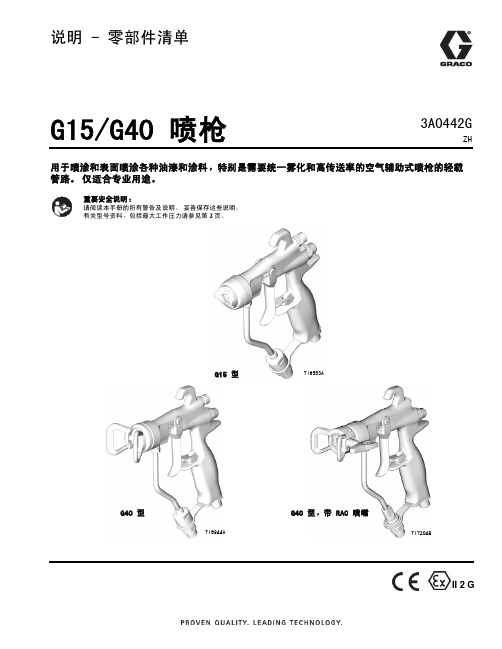
说明 - 零部件清单G15/G40 喷枪用于喷涂和表面喷涂各种油漆和涂料,特别是需要统一雾化和高传送率的空气辅助式喷枪的轻载管路。
仅适合专业用途。
妥善保存这些说明。
3页。
G15 型TI6553AG40 型TI6844ATI7204BG40 型,带 RAC 喷嘴II 2 G3A0442GZH目录型号 . . . . . . . . . . . . . . . . . . . . 3警告 . . . . . . . . . . . . . . . . . . . . 4安装 . . . . . . . . . . . . . . . . . . . . 6典型安装 . . . . . . . . . . . . . . . . . 6喷涂间要通风 . . . . . . . . . . . . . . . 6接地 . . . . . . . . . . . . . . . . . . . 6空气管路 . . . . . . . . . . . . . . . . . 7流体管路 . . . . . . . . . . . . . . . . . 7设置 . . . . . . . . . . . . . . . . . . . . 8使用前冲洗设备 . . . . . . . . . . . . . . 8选择喷嘴 . . . . . . . . . . . . . . . . . 8空气帽定位销 . . . . . . . . . . . . . . . 8安装喷嘴 . . . . . . . . . . . . . . . . . 8空气帽的定位 . . . . . . . . . . . . . . . 8 Reverse-A-Clean® (RAC) 喷嘴组件 . . . . . 9操作 . . . . . . . . . . . . . . . . . . . .10泄压步骤 . . . . . . . . . . . . . . . . .10扳机锁 . . . . . . . . . . . . . . . . . .10空气辅助式无气喷枪是如何工作的 . . . . . .11喷型的调节 . . . . . . . . . . . . . . . .11 HVLP 操作 . . . . . . . . . . . . . . . .12流体的喷涂 . . . . . . . . . . . . . . . .12喷枪的每日养护、冲洗和清洗 . . . . . . . . . 13系统的一般维护 . . . . . . . . . . . . . 14流体过滤器的维护 . . . . . . . . . . . . 14冲洗和清洗 . . . . . . . . . . . . . . . 14 Reverse-A-Clean (RAC) 喷嘴® . . . . . . 16故障排除 . . . . . . . . . . . . . . . . . . 18修理 . . . . . . . . . . . . . . . . . . . . 20修理配件包 . . . . . . . . . . . . . . . 20更换喷幅阀 . . . . . . . . . . . . . . . 20喷枪密封的全面修理 . . . . . . . . . . . 20零部件 . . . . . . . . . . . . . . . . . . . 26喷嘴选择表 . . . . . . . . . . . . . . . . . 32喷嘴,配用于G15/G40 空气帽 . . . . . . . 32 RAC SwitchTips 喷嘴,配用于 G40 空气帽 . 33 RAC SwitchTips 喷嘴,配用于 G40 RAC 空气帽(续) . . . . . . . . . . . . . . . . 34附件 . . . . . . . . . . . . . . . . . . . . 35零部件互换指南 . . . . . . . . . . . . . 37尺寸 . . . . . . . . . . . . . . . . . . . . 38技术数据 . . . . . . . . . . . . . . . . . . 39 Graco Standard Warranty . . . . . . . . . . 40 Graco Information . . . . . . . . . . . . . 4023A0442G型号3A0442G 3型号部件系列最大工作空气压力psi (MPa, bar)最大流体工作压力psi (MPa, bar)说明包括:24C853A 100 (0.7, 7.0)1500 (10.5, 105)G15 型中压空气辅助式喷枪,碳钢阀座和球24C866 带定位销的空气帽24C854A100 (0.7, 7.0)1500 (10.5, 105)G15 型中压空气辅助式喷枪,塑料阀座,不锈钢球26A826A 100 (0.7, 7.0)1500 (10.5, 105)G15 型中压空气辅助式喷枪,碳钢阀座和球,漆空气帽26A824带定位销的空气帽24C855A 100 (0.7, 7.0)4000 (28, 280)G40 型高压空气辅助式无气喷枪,碳钢阀座和球249180 无定位销空气帽24C856A100 (0.7, 7.0)4000 (28, 280)G40 高压、大流量空气辅助式喷枪,碳钢阀座和球24C857A100 (0.7, 7.0)4000 (28, 280)G40 型高压空气辅助式无气喷枪,碳钢阀座和球,Reverse-A-Clean (RAC) 喷嘴®24C921 RAC 空气帽警告警告以下为与本设备的设置、使用、接地、维护及修理有关的一般性警告。
德龙牌喷枪说明书

德龙牌喷枪说明书
喷枪是利用液体或压缩空气迅速释放作为动力的一种设备,通常用于喷洒、清洁,例如喷水枪;或者用于喷涂,表面处理,例如喷漆枪。
又因安装于机器上分为自动喷枪或手工使用区别为手动喷枪。
喷枪使用的方法
方法/步骤
1、首先新买来的喷枪一般都涂有防腐油,我们要先用肥皂水将其清洗干净。
2、将油漆摇匀后倒入漆杯,过程中让油漆完全滴入漆杯后尽快盖上盖子,防止油漆分解或变干,荣鹏气动工具操作标准。
3、喷涂油漆时,先在废料上测试一下喷涂的痕迹是否正常,正常后开始喷涂,喷枪应距被喷涂面12-20厘米。
方法/步骤2
4、喷枪应始终与被喷涂面保持垂直的角度,保持相等的距离,平行移动。
每次的喷涂痕迹应与上次的重叠三分之一,气动工具喷涂标准。
5、喷枪的速度移动应适当,不能过快或过慢。
从上往下涂上速度应该过快,以避免油漆积聚下流或局部涂层过厚。
油漆喷枪可以按不同的方面分为不同的类型,按油漆的输送方式可分为普通式和压送式;按罐的位置可分为上壶式和下壶式。
喷灌喷枪的使用方法及调节
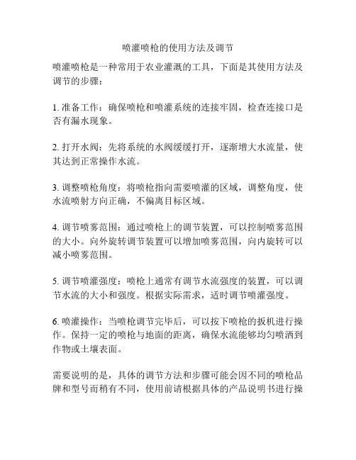
喷灌喷枪的使用方法及调节
喷灌喷枪是一种常用于农业灌溉的工具,下面是其使用方法及调节的步骤:
1. 准备工作:确保喷枪和喷灌系统的连接牢固,检查连接口是否有漏水现象。
2. 打开水阀:先将系统的水阀缓缓打开,逐渐增大水流量,使其达到正常操作水流。
3. 调整喷枪角度:将喷枪指向需要喷灌的区域,调整角度,使水流喷射方向正确,不偏离目标区域。
4. 调节喷雾范围:通过喷枪上的调节装置,可以控制喷雾范围的大小。
向外旋转调节装置可以增加喷雾范围,向内旋转可以减小喷雾范围。
5. 调节喷灌强度:喷枪上通常有调节水流强度的装置,可以调节水流的大小和强度。
根据实际需求,适时调节喷灌强度。
6. 喷灌操作:当喷枪调节完毕后,可以按下喷枪的扳机进行操作。
保持一定的喷枪与地面的距离,确保水流能够均匀喷洒到作物或土壤表面。
需要说明的是,具体的调节方法和步骤可能会因不同的喷枪品牌和型号而稍有不同,使用前请根据具体的产品说明书进行操
作。
此外,注意安全使用喷灌喷枪,避免将水流喷向人身或其他不需要喷灌的区域。
Metco F4MB-XL系列等离子喷枪说明书

Metco F4MB-XL 系列等离子喷枪操作特别可靠,客户可放心使用。
用于 Metco F4MB-XL 系列喷枪的欧瑞康美科配件系生产于我公司ISO 9001 认证工厂,生产过程质量把控严格。
高品质备件经设计,使用寿命长、安全性高,可确保高效生产和重复喷涂。
1 基本说明Metco F4MB-XL 系列等离子喷枪是一种机装型、多用途大气等离子喷枪,适用于外表面喷涂。
Metco F4MB-XL 系列等离子喷枪可采用氩、氢和氦等离子气体组合进行操作。
还可针对氮和氮氢等离子混合气体,配装特殊喷嘴。
喷枪硬件采用多用途、安全和便捷操作设计。
喷枪电缆接头分左右线路,可消除意外(正、负)极性倒转造成的喷枪严重损坏。
连接处封闭在喷枪罩壳内,从而将其与热喷涂环境隔开,同时避免操作员触电。
水用作冷却介质。
可施用许多多层材料,而无需在粘结层和面层之间更换各种硬件。
Metco F4MB-XL 系列喷枪经设计可在高达 55 kW 功率下高效操作。
与可兼容的欧瑞康美科等离子控制器配套运行时,欧瑞康美科等离子控制器会对电功率、等离子气体压力与流量、喷枪冷却水温度与流量及空气压力进行持续监测和控制。
该系列喷枪为多种材料高完整性涂层,包括金属、合金、陶瓷、碳化物、金属陶瓷、封严材料、复合材料、混合材料,以及欧瑞康美科提供用于大气等离子喷涂的广泛综合材料。
产品说明书Metco F4MB-XL 系列Metco ™ F4MB-XL 系列等离子喷枪是欧瑞康美科F4MB 最新一代产品。
F4MB 大气等离子喷枪采用机械安装,数十年来深受客户喜爱。
其最新一代产品经重新设计后,稳定性更好,同时还保留其所有原有优点。
Metco F4MB-XL 系列等离子喷枪经设计,性能可靠,同时有效利用等离子喷涂工艺性能,可带来符合或超越许多原始设备制造商规格要求的高质量涂层。
采用高性能和灵活性设计,Metco F4MB-XL 系列等离子喷枪符合欧洲CE 设备安全要求。
TME 热胶喷枪操作手册说明书
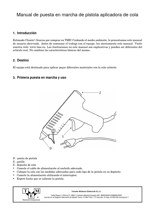
Manual de puesta en marcha de pistola aplicadora de cola1.IntroducciónEstimado Cliente!Gracias por comprar en TME!Cuidando el medio ambiente,le presentamos este manual de usuario abreviado.Antes de comenzar el trabajo con el equipo,lea atentamente este manual.Visite nuestra web:s ilustraciones en este manual son explicativas y pueden ser diferentes del artículo real.No cambian las características básicas del mismo.2.DestinoEl equipo estádestinado para aplicar pegar diferentes materiales con la cola caliente.3.Primera puesta en marcha y usoD-punta de pistolaS-gatilloZ-deposito de cola•Conecte el cable de alimentación al enchufe adecuado.•Coloque la cola con las medidas adecuadas para cada tipo de la pistola en su depósito.•Conecte la alimentación utilizando el interruptor.•Espere hasta que se caliente la pistola.•Aplique la cola aprietando lentamente el gatillo de la pistola.4.Precauciones•Para proteger la salud y evitar daños corporales,choque eléctrico,incendio o explosión,se debe tener en cuenta las siguientes instrucciones de seguridad.El incumplimiento de las normas de seguridad puede provocar el riesgo para la vida y la salud.Guarde el presente manual y los concejos de seguridad en un sitio cerca del equipo.•El cable de alimentación puede ser conectado solamente al conchufe adecuado o al prolongador de alimentación con tierra.•Antes de conectear la clavija al enchufe,asegúrese de que el interruptor estéen la posición OFF.•Siempre desconecte el cable de alimentación del equipo antes de reponer un fusible o accesorios adicio-nales.•Utilice solamente el equipamiento adicional adecuado.•No vuelque la pistola en funcionamiento hacia atrás.•Si no utiliza el equipo,desenchufe el cable de alimentación;no deje el equipo encendido sin supervisión.•Utilice solamente cola en barritas destinadas para las pistolas aplicadoras de cola.•Durante el trabajo se debe sujetar la herramienta por las partes aisladas como por ejemplo mangos o soporte destinado para esto y evitar el contacto del cuerpo con los elementos que conducen la corriente (tuberías,radiadores etc.).•No toque los elementos calientes de la pistola,en caso de contacto de la piel con la cola caliente,inme-diatamente limpie la quemadura bajo un chorro del agua fría.•Mantenga el equipo fuera del alcance de los niños.•Evite la exposición a la luz del sol directa,la lluvia,etc.•No encienda el equipo inmediatamente después de trasladarlo de un lugar frío al conden-sación puede dañar el equipo.•Utilice el equipo de acuerdo con su uso previsto;el uso inadecuado puede dañar el equipo,causar un choque eléctrico,lesiones o muerte.•Las reparaciones deben ser realizadas por personal cualificado,utilizando piezas de repuesto adecuadas.•Estáprohibido hacer cambios estructurales.Los cambios estructurales no autorizados supondrán la pérdida de la garantía y también pueden provocar un mal funcionamiento o causar un accidente.•En su caso,no cubra ni tape las rejillas de ventilación.•No se deben superar los parámetros nominales de funcionamiento del equipo.•Los equipos eléctricos y electrónicos usados no se deben almacenar junto con otros residuos.Los equipos eléctricos y electrónicos usados se deben almacenar en lugares destinados para este fin.•En caso de taparse la punta de pistola,debe limpiarla antes de continuar trabajando.•Observe el manual de usuario de la herramienta.。
油漆喷枪使用说明书
油漆喷枪使用说明书它是我们在喷涂施工中的主要操作设备,根据取料方式以分为三种:虹吸式、重力式和压送式。
因除对嘴式喷枪外,不论是其它虹吸式还是重力式都可以很方便的改为压送式,所以我们一般只把喷枪分为两种:虹吸式和重力式。
1.虹吸式喷枪(虹吸式喷枪外部结构如下图)虹吸式喷枪又分为对嘴式和扁嘴式两种。
对嘴式喷枪一般重量较轻,仅0.5公斤左右,贮料罐容量小,工作压力一般在0.274~0.345兆帕,喷涂时喷雾呈圆形,喷嘴与工件物面间距150~250毫米,仅适用于小工件的喷涂作业,所以又俗称小喷枪。
扁嘴式喷枪相应要重一些,约1公斤,贮料罐容量较大,喷涂气压一般控制在0.35~0.50兆帕,喷涂间距较大,约在250~350毫米,属于大型喷枪。
喷涂时喷雾由旋转螺冒调节控制,可呈圆形、扇形或圆锥形(旋紧),喷涂时应根据被涂物表面形状和施工现场情况而调整喷雾形态。
2.压下式喷枪压下式喷枪又称重力式喷枪,其构造和工作原理基本上与扁嘴式喷枪相同,只是贮料罐上方,涂料靠重力作用自行流入枪膛,并随压缩空气喷射在工件上。
贮料罐装在上方,即使涂料较少,亦可充分得到利用,这是它的优点。
但枪体重心上移,如装满涂料,重量较大,不便于枪体运作,且涂料又易溢出,影响操作。
3.压送式喷枪压送式喷枪其构造和工作原理基本上与压下式喷枪和虹吸式的扁嘴喷枪一样,其喷枪本身就是由扁嘴喷枪改造而成,不同的只是供料方式不一样而已,扁嘴式喷枪由贮料罐供料,压送式喷枪采用输漆泵供料。
4.常用喷枪的内部结构及各种控制阀门的作用①.枪头扁嘴(旋转螺母)枪头扁嘴主要是用来控制喷涂漆雾的形状和方向。
枪头扁嘴与枪身呈垂直或平行时,漆雾方向与枪头扁嘴的方向相反,漆雾呈扇形。
枪头扁嘴与枪身呈45°角交差时,漆雾呈圆形,角度变小或增大时,漆雾由圆形向椭圆变化,至180°角时变成扇形。
②.漆雾面积调节阀漆雾面积调节阀又称扇面调节阀,它在枪体的右上方,流量调节阀的上面。
JET JAT-500 HVLP 涂料喷枪操作指南说明书
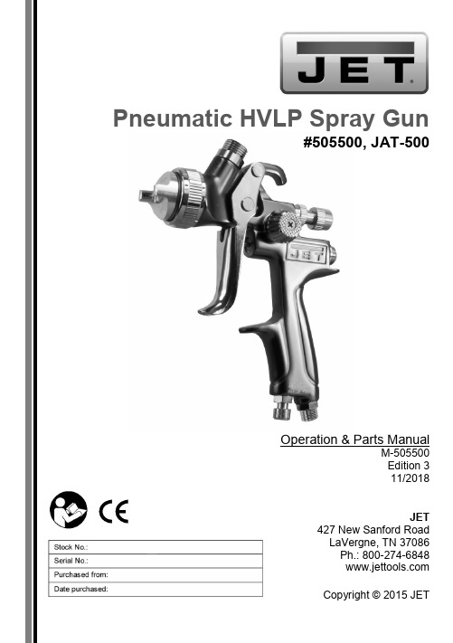
Pneumatic HVLP Spray Gun#505500, JAT-500Operation & Parts ManualM-505500Edition 311/2018JET427 New Sanford RoadLaVergne, TN 37086Ph.: 800-274-6848Copyright © 2015 JETWarranty and ServiceJET warrants every product it sells against manufacturers’ defects. If one of our tools needs service or repair, please contact Technical Service by calling 1-800-274-6846, 8AM to 5PM CST, Monday through Friday.Warranty PeriodThe general warranty lasts for the time period specified in the literature included with your product or on the official JET branded website.JET products carry a limited warranty which varies in duration based upon the product. (See chart below)Accessories carry a limited warranty of one year from the date of receipt.Consumable items are defined as expendable parts or accessories expected to become inoperable within a reasonable amount of use and are covered by a 90 day limited warranty against manufacturer’s defects.Who is CoveredThis warranty covers only the initial purchaser of the product from the date of delivery.What is CoveredThis warranty covers any defects in workmanship or materials subject to the limitations stated below. This warranty does not cover failures due directly or indirectly to misuse, abuse, negligence or accidents, normal wear-and-tear, improper repair, alterations or lack of maintenance. JET woodworking machinery is designed to be used with Wood. Use of these machines in the processing of metal, plastics, or other materials outside recommended guidelines, may void the warranty. The exceptions are acrylics and other natural items that are made specifically for wood turning.Warranty LimitationsWoodworking products with a Five Year Warranty that are used for commercial or industrial purposes default to a Two Year Warranty. Please contact Technical Service at 1-800-274-6846 for further clarification.How to Get Technical SupportPlease contact Technical Service by calling 1-800-274-6846. Please note that you will be asked to provide proof of initial purchase when calling. If a product requires further inspection, the Technical Service representative will explain and assist with any additional action needed.JET has Authorized Service Centers located throughout the United States. For the name of an Authorized Service Center in your area call 1-800-274-6846 or use the Service Center Locator on the JET website.More InformationJET is constantly adding new products. For complete, up-to-date product information, check with your local distributor or visit the JET website.How State Law AppliesThis warranty gives you specific legal rights, subject to applicable state law.Limitations on This WarrantyJET LIMITS ALL IMPLIED WARRANTIES TO THE PERIOD OF THE LIMITED WARRANTY FOR EACH PRODUCT. EXCEPT AS STATED HEREIN, ANY IMPLIED WARRANTIES OF MERCHANTABILITY AND FITNESS FOR A PARTICULAR PURPOSE ARE EXCLUDED. SOME STATES DO NOT ALLOW LIMITATIONS ON HOW LONG AN IMPLIED WARRANTY LASTS, SO THE ABOVE LIMITATION MAY NOT APPLY TO YOU.JET SHALL IN NO EVENT BE LIABLE FOR DEATH, INJURIES TO PERSONS OR PROPERTY, OR FOR INCIDENTAL, CONTINGENT, SPECIAL, OR CONSEQUENTIAL DAMAGES ARISING FROM THE USE OF OUR PRODUCTS. SOME STATES DO NOT ALLOW THE EXCLUSION OR LIMITATION OF INCIDENTAL OR CONSEQUENTIAL DAMAGES, SO THE ABOVE LIMITATION OR EXCLUSION MAY NOT APPLY TO YOU.JET sells through distributors only. The specifications listed in JET printed materials and on official JET website are given as general information and are not binding. JET reserves the right to effect at any time, without prior notice, those alterations to parts, fittings, and accessory equipment which they may deem necessary for any reason whatsoever. JET® branded products are not sold in Canada by JPW Industries, Inc.NOTE: JET is a division of JPW Industries, Inc. References in this document to JET also apply to JPW Industries, Inc., or any of its successors in interest to the JET brand.2 JAT-500 HVLP Spray GunSafety warningsGeneral air tool warnings1. Read and understand this entire manualbefore attempting assembly or operation.2. Read and understand all warnings posted onthe tool and in this manual. Failure to comply with all of these warnings may cause serious injury.3. Replace warning labels if they becomeobscured or removed.4. Do not use this tool for other than its intendeduse. If used for other purposes, JET disclaims any real or implied warranty and holds itself harmless from any injury that may result from that use.5. Always wear approved safety glasses or faceshield while using this tool. (Everyday eyeglasses only have impact resistant lenses;they are not safety glasses.)6. Wear ear protectors (plugs or muffs) if thenoise exceeds safe levels.7. Wear gloves and protective clothing ifoperation produces sparks or flying particles.Gloves should be tight-fitting, without frayed fingers or hanging threads. Keep hands and body away from the working area of tool.8. Do not operate an air tool continually at fullthrottle without a work load on the tool.9. The air tool must be properly lubricated beforeoperating.10. Never start a percussion type air tool (chipper,breaker, buster, etc.) without securing the tooling in the retainer and placing the tip against the work surface.11. Do not operate air tool without its guards inplace. Do not modify the tool. 12. Do not operate this tool while tired or underthe influence of drugs, alcohol, or any medication.13. Adopt a comfortable posture with properbalance, and maintain secure footing at all times. Non-slip footwear or anti-skid floor strips are recommended.14. Do not wear loose clothing or jewelry. Confinelong hair.15. Excessive air pressure and too much freerotation may decrease life of the tool and may cause a hazardous situation.16. Check air hoses for wear, and keep themaway from heat and sharp edges. Repair or replace damaged air hose immediately. Do not carry tool by the air hose.17. Air hose may cause tripping hazards; keephose away from traffic areas.18. Do not use this tool near flammable objects,or in potentially explosive environments. Do not use near live electrical wires.19. Do not use power tools in damp or wetlocation, or expose them to rain. Keep work area well lighted.20. Do not leave a connected tool unattended.When not in use, disconnect tool from air source.21. Shut off air supply and discharge any residualpressure from tool before removing hose,making adjustments, changing accessories, or storing tool.22. Make sure tool is switched off, and your fingeroff the trigger, before connecting to air supply.23. Remove adjusting keys and wrenches beforeturning on tool.24. Keep visitors a safe distance from the workarea. Keep children away.JET 325. Give your work undivided attention. Lookingaround, carrying on a conversation and “horse-play” are careless acts that can result in serious injury.26. Do not force a tool or attachment to do a jobfor which it was not designed. The right tool will do the job better and more safely.27. Repetitive motions and/or exposure toconstant vibration can be harmful to hands and arms. Take frequent breaks and relax hands during extended operation. Change posture to avoid discomfort or fatigue.28. Compressed air can be harmful if directedtoward sensitive areas of the body, and may propel small particles caught in the air stream.Exercise proper caution.29. Use only recommended accessories;improper accessories may be hazardous. 30. Maintain tools with care. Keep air tool cleanand oiled for best and safest performance. 31. Do not use combustible gases, carbondioxide, oxygen or any bottled gas as an air source for the tool. These can present risk of explosion and serious injury.32. Do not lubricate the tool with combustibleliquids, such as kerosene, diesel or jet fuel.33. Do not dispose of this tool with normalhousehold waste. Never dispose of the air tool into fire.Specific warnings for Spray Guns 34. Solvent and paint fumes can ignite causing anexplosion. Exercise caution and use appropriate ventilation systems. It is the responsibility of the owner to understand and comply with any codes or regulations concerning hazardous materials.35. Wear appropriate eye and respiratoryprotection when using this spray gun.36. Read, understand and follow all safetywarnings by the material and solvent manufacturer. 37. Do not spray flammable materials near openflames, pilot lights or other sources of ignition.Familiarize yourself with the following safety notices used in this manual:This means that if precautions are not heeded, it may result in serious, or even fatal, injury.This means that if precautions are not heeded, it may result in minor injury and/or possible tool damage.WARNING: This product can expose you to chemicals including lead which is known to the State of California to cause cancer and birth defects or other reproductive harm. For more information go to http://www. p65warnings.ca. gov.WARNING: Some dust, fumes and gases created by power sanding, sawing, grinding, drilling, welding and other construction activities contain chemicals known to the State of California to cause cancer and birth defects or other reproductive harm. Some examples of these chemicals are:lead from lead based paintcrystalline silica from bricks, cement andother masonry productsarsenic and chromium from chemicallytreated lumberYour risk of exposure varies, depending on how often you do this type of work. To reduce your exposure to these chemicals, work in a well-ventilated area and work with approved safety equipment, such as dust masks that are specifically designed to filter out microscopic particles. For more information go to / and http:// /wood.4 JAT-500 HVLP Spray GunAbout this manualThis manual is provided by JET, covering the safe operation and maintenance procedures for a JET Model JAT-500 Pneumatic Spray Gun. This manual contains instructions on safety precautions, general operating procedures, maintenance procedures and parts breakdown. Your tool has been designed and constructed to provide consistent, long-term operation if used in accordance with the instructions set forth in this document.The instructions and warnings in this manual may not encompass all possible workplace environments. The operator is expected to take appropriate precautions and exercise common sense. As with any tool operation, safety of operator and bystanders should be first priority.If there are questions or comments, please contact your local supplier or JET. JET can also be reached at our web site: .Record the serial number and purchase information of your tool on the cover of this manual for quick access. Retain this manual for future reference. If the tool transfers ownership, the manual should accompany it.JET 5Tool specificationsStock number 505500Gun type HVLP (High Volume Low Pressure)Feed type GravityCup capacity 600ccFluid nozzle provided 1.3 mmFluid output 170 cc/minMaximum fan pattern size 280 mmAir consumption 10 CFM at 28 PSI (2 bar)Working pressure 15-28 PSI (1.05-2 bar)Air Inlet 1/4 in. PSFluid inlet M16 x 1.5POverall length 13.1 in. (332.74 mm) with cap; 7.87 in. (200 mm) without cap Body material Die castingFluid tip and needle material Stainless steelNet weight, gun body 1.01 lb. (0.46 kg)Net weight, accessories 0.59 lb. (0.27 kg)Shipping weight 2.05 lb. (0.93 kg)1 The specified values are emission levels and are not necessarily to be seen as safe operating levels. As workplace conditions vary, this information is intended to allow the user to make a better estimation of the hazards and risks involved only.Specifications were current at time of publication, but because of our policy of continuous improvement, JET reserves the right to change specifications at any time and without prior notice, without incurring obligations.6 JAT-500 HVLP Spray GunSetup and AssemblyAny missing parts or damage should be reported immediately to your JET® distributor. Do not use a damaged tool. Read this instruction manual thoroughly for operation, maintenance and safety instructions.Box contents:1 Spray gun1 Gravity feed cup, 600cc1 Nylon strainer1 Spanner1 Bristle brush1 Operation and parts manual1 Warranty cardOperation1. Blow out air line to remove any dirt ormoisture, then connect air supply hose totool’s air inlet.IMPORTANT:Connecting a quick-changecoupling directly to the tool is notrecommended, as vibration may cause theconnection to fail. Instead, add a leader hoseand install any quick-change couplingsfarther down the line.2. Unscrew cup lid and add fluid to be sprayed.(Follow paint manufacturer’s instructions forproper mixing.)3. Set regulator to desired air pressure. (Referto gun’s rated maximum pressure).4. Loosen air cap knurled ring and rotate air caphorns to effect horizontal or vertical spray.Retighten air cap.Horizontal horns (as shown in Figure 1) willproduce vertical pattern for side-to-sidemotion. Vertical horns produce horizontalpattern used for top-to-bottom motion.5. Squeezing trigger part way opens air valve.Squeezing further retracts fluid needle, thusreleasing fluid where it is atomized by the airflowing through air cap.6. Rotate fluid control knob clockwise todecrease flow of material, counterclockwiseto increase. 7. Rotate fan control knob counterclockwise forfull, flat spray pattern; clockwise for narrowerpattern.NOTE: To reduce overspray and obtain maximum efficiency, always spray with the lowest possible air pressure/fluid flow combination.Figure 1Spray gun movementThe gun should be held perpendicular to surface being covered, and moved parallel with it at aconsistent pace. See Figure 2. The stroke should be started before the trigger is pulled, and the trigger released before the stroke is ended. Distance between gun and surface should be 6 to 12 inches depending upon material and atomizing pressure.Deposited material should be even and wet. Lap each stroke over the preceding stroke from 1/3 to 1/2, to obtain a uniform finish.JET 78 JAT-500 HVLP Spray GunFigure 2MaintenanceNote: All parts on a spray gun should be screwed in hand tight at first; this will avoid the possibility of cross threading the parts. If parts cannot be turned by hand easily, make sure you have the correct parts, unscrew, realign and try again. Never use undue force in mating parts.All nozzles and needles are precision made – they should be handled carefully. When changing to a different nozzle size, make sure that complete nozzle set is exchanged (air cap/nozzle/needle). Adjust fluid control knob so that when gun is triggered, air-flow occurs before fluid-flow. Do not probe any holes innozzle with metal instruments, as damage to spray gun can affect proper operation.Cleaning1.After use, remove cup and drain residual material. Rinse cup with a cleaning solution or water, depending upon material used. Place cleaning solution into cup and install on gun. Spray solution through the gun untilit sprays clear. Do NOT immerse the entire gun in solvent. 2. Disconnect air hose from tool.3. Remove air cap and clean. Make sure holes in horns are clean.4. Use solvent and the provided brush to remove any deposits around fluid nozzle.5.For more detailed cleaning, use provided spanner to remove fluid control knob, fluid nozzle, and needle (in that order). Clean nozzle and needle with brush and solution. Reassemble parts by reversing above order. 6.Periodically lubricate the gun. Use a light machine oil (Air Tool Oil or SAE #10) on the following areas. Do not use lubricants containing silicone. Fluid needle packing (to prevent needle from sticking) Air valve packing Trigger pivot pointThreaded partsStorageHang the spray gun by its hook when not in use, to prevent leaks or blockages. Disconnect air hose before storage.Air system requirements1.Use proper air hose size (refer to tool specifications). The hose should be just long enough to serve the working area. Excessive hose length will cause pressure drop. 2. Make sure air compressor supplies clean, dry air at correct CFM for tool.3.Set air pressure according to tool specifications.Excess air pressureand/or unclean air will shorten the tool’s life and may create a hazardous situation. 4.Drain water from air compressor tank daily, as well as any condensation from air lines.Water in the air line may enter the tool and cause damage.5.Change filters on the air system on a regular basis.6. Air-line pressure may be increasedaccordingly to compensate for extra-long airhoses (usually over 25 feet). Inside diameterof hose should be minimum 3/8-inch. General Air Tool InformationIf the air tool is not performing according to specifications, the following are among the most common causes. (See also “Troubleshooting” section.)Contaminated air such as a dirty air system or water in the system.Using wrong size tool for the job.Poor maintenance practices, such as using excessive air pressure or air volume.Improper or no lubrication.Air System RecommendationsEquip the air compressor intake with a replaceable air filter that can be easily cleaned. Use safety shut-off valves so air flow can be stopped quickly in case of a line break.When using multiple hoses, air hoses should be larger than leader hose. Join multiple hoses directly, rather than with quick connect fittings which may cause pressure drops and tool power reduction.Use anti-whip devices across hose couplings to prevent hose from whipping in the event of a hose failure or coupling disconnect.Always use moisture traps at the compressor for the main distribution line. Use moisture traps on each downline that is to be used for air tools. RecyclingProtect the environment. Your tool contains materials which can be recovered or recycled. When its useful life has expired, please leave tool at a specialized facility.JET 9Troubleshooting JAT-500 Spray GunAny disassembly of the tool should be done by qualified service personnel. For problems not addressed below, contact JET technical service at 800-274-6846.Correct normal pattern. No correction necessary.Dirty or damaged air cap.Dirty or damaged fluid tip.Rotate air cap 180-degrees:If pattern is following air cap,problem is in air cap. Clean andinspect. If pattern does not correct,replacement is necessary.If pattern is NOT following air cap,problem is with fluid tip. Clean andinspect tip for dried paint, dirt ordamage. If pattern does notcorrect, replacement is necessary.Pressure too high for materialviscosity being sprayed.Reduce air pressure.Increase material viscosity.Pattern may also be corrected bynarrowing fan size with spray widthadjuster control knob.Dirty or distorted air horn holes. Rotate air cap 180-degrees:If pattern is following air cap,problem is in air cap. Clean andinspect the horn holes. If hornholes are distorted, replacement isnecessary.One of the air horn holescompletely obstructed.Air getting into paint stream. Check and tighten fluid needlepacking nut.Tighten fluid nozzle.Check fluid nozzle seat fordamage.Check for poor gun-to-cup seating.Check that cup is correctlyfastened on gun.Material bubbles or “boils”in cup.Excess air blowing back into cup. Tighten fluid nozzle.Check fluid nozzle seat.Check for damaged fluid seat onnozzle or seat on gun head.10 JAT-500 HVLP Spray GunSpray nozzle applicationsBelow are general applications for accessory nozzles available for this spray gun. This is only a general guide; consult the fluid material manufacturer for more information on efficient use of their product.Replacement partsService parts are listed on the following pages. To order parts or reach our service department, call 1-800-274-6848 Monday through Friday, 8:00 a.m. to 5:00 p.m. CST. Please have the stock number and serial number of your tool available when you call, so that we may serve you quickly and accurately.#505500, JAT-500, HVLP Spray Gun – exploded view#505500, JAT-500, HVLP Spray Gun – parts listJAT500-RPK, Repair Kit, contains 6,7,10,14,15,24(2) JAT500-NK, Replacement Nozzle Kit 1.3mm, contains #1,2,9Accessories for JAT-500:505590, 600cc Aluminum cup with plastic lid505591, Nozzle kit 1.4mm (includes air cap, fluid nozzle and fluid needle) 505592, Nozzle kit 1.7mm (includes air cap, fluid nozzle and fluid needle) 505593, Nozzle kit 2.1mm (includes air cap, fluid nozzle and fluid needle) 505596, Spray Gun Cleaning Kit, 17pc.505596427 New Sanford Road LaVergne, Tennessee 37086 Phone: 800-274-6848。
- 1、下载文档前请自行甄别文档内容的完整性,平台不提供额外的编辑、内容补充、找答案等附加服务。
- 2、"仅部分预览"的文档,不可在线预览部分如存在完整性等问题,可反馈申请退款(可完整预览的文档不适用该条件!)。
- 3、如文档侵犯您的权益,请联系客服反馈,我们会尽快为您处理(人工客服工作时间:9:00-18:30)。
m3/min
二、 喷嘴压力-流量曲线图
S20 压力-流量曲线
300.03
0.6
205.20 5
0.5
(耗
耗气量(NL/min)
气 200.02 0.4 )
量
015.105
Pa=0.3Mpa
0
0
10
Pw=0.2Mpa
20喷雾量(L/h)0.来自 0.33040
S60 压力-流量曲线
02.2505
0.6
200.02
0.5
(耗
耗气量(NL/min)
0.4
) 气 01.5105
量
Pa=0.3Mpa
100.01
Pw=0.2Mpa
0.4 0.3
m3/min
0
10
20
30
40
50
60
喷雾量(L/h)
70
80
90
------Pw : 表示液体压力(MPa) --------Pa :表示压缩空气压力(MPa)
m3/min
四、 TX 系列喷枪分类
1. TX1 系列-----带气动伸缩装置脱硝专用喷枪
二联件
电磁阀 电磁阀
保护套管
进液口
气缸 进气口
喷枪采用气动伸缩装置,喷枪不使用时可自动退出炉内,大大延长了喷枪的使用寿命; 采用保护碳化硅保护套管,具有耐高温、耐磨损等特点,无需另设冷却装置就可确保喷
枪长期安全、稳定运行; 喷枪外观漂亮、结构紧凑、拆卸及维护非常方便。
01.1757 5
0.6
01.5105
0.5
(耗
耗气量(NL/min)
气 01.2152
)
5
量
010.10
0.4 Pa=0.3Mpa
Pw=0.2Mpa
0.4 0.3
0
0
10
20
30
40
50
60
70
80
喷雾量(L/h)
m3/min
F90 压力-流量曲线
03.5305
0.5
300.03
耗气量(NL/min)
六、 喷枪的运行
1. 检查喷枪安装情况-----根据安装图纸对喷枪进行确认,主要检查喷嘴喷雾方向是否与烟 气流动方向垂直,电磁阀电源线是否连接,行程开关接线是否正确,再通电测试。
2. 开启前检查-----检查总管阀门是否开启,旁路阀门是否关闭,确保水路和气路的畅通; 先开启气路阀门,把气压稳定在 0.4Mpa。再打开液路阀门,水路阀门开到最大。
TX 系列喷枪的特点: 雾化效果好,平均雾化颗粒直径只有 60 微米。经过喷嘴雾化后,在同样喷水量情况下, 雾滴数量增加几十倍,液滴总表面积增加几倍,所以脱硝效率更高,氨逃逸率更低。 穿透性强,水雾从喷嘴出口喷出时速度到达 40m/s,保证了还原剂能够与烟气充分混合, 从而提高了脱硝效率。 规格齐全,流量从 3kg/h 到 250kg/h,喷雾形状有实心锥和扇形,总有一款适合您的需 求。 单支喷枪流量调节比大,流量调节比达到 1:5,再加上多支喷枪的组合开关,总流量肯 定能适合任何工况的需要。 控制简单,工作时气压不变,仅靠调节水压就能达到调节水量的目的,而且水量变化对 喷雾颗粒影响很小。 使用寿命长,因为喷嘴工作在低压环境下,水压气压都不超过 0.6Mpa,所以对喷嘴磨 损很小,喷枪外带碳化硅保护套管,喷嘴完全置于保护套管内,避免高温、高粉尘及高流速 烟气对喷嘴的磨损。 多种安装方式,有法兰连接、快速接头连接和螺纹连接几种连接方式可供选择 广泛适用于电站锅炉、水泥、垃圾焚烧等行业的烟气脱硝
上海守望者喷雾智能系统有限公司
TX 系列喷枪说明书
一、 TX 喷枪简介
TX 喷枪是一款专为脱硝工程设计的双流体雾化喷枪,其雾化原理为二级破碎+空气混合 +气流摩擦。喷枪根据结构方式不同分为 TX1、TX2、TX3 三种规格;脱硝喷枪所用喷嘴根据 流量和喷雾形状分为 S20、S60、S150 和 F20、FM30、F40、F90 共两个规格 7 种型号,其中 S 系列喷雾形状为 20 窄角实心锥,F 系列喷雾形状为广角扇形。
25
33
30
38
33
41
18
23
23
30
25
33
30
38
33
41
18
20
25
30
25
30
33
41
36
43
C(厘米)
20 33 46 46 48 30 41 43 48 51 25 43 46 53 58
D(米)
3.0 3.2 3.4 3.5 4.0 3.4 3.5 3.7 3.8 4.4 3.4 3.8 4.3 4.6 5.2
喷枪退进到位或退出到位时,有推进到位或退出到位位置反应接近开关,2 个接近开关 为磁感应开关,需要串入 24V 内才能使用,磁感应开关为 2 线输出(棕色线为正,蓝色线为 负),需要接对 2 线,到位后磁感应开关上的红灯会亮。
F. 喷枪平时维护时只需将喷枪枪杆拆卸下来即可,喷枪整体包括伸缩机构在内可以不用拆 卸下来。拆卸喷枪枪杆时只需将禁锢螺母和快拆接头拆下后即可将喷枪枪杆从喷枪本体 上分离开。(见下图)
型号 S20 S60 S150
空气压力(bar) 液体压力(bar)
1.7
0.7
2.8
1.5
3.9
2.0
5.3
3.0
6.0
4.0
1.0
0.7
1.8
1.5
2.8
2.0
3.5
3.0
4.9
4.0
1.0
0.7
1.7
1.5
2.4
2.0
3.1
3.0
3.8
4.0
喷雾尺寸
喷雾角度 A
18° 20° 20° 21° 21° 17° 18° 20° 20° 21° 19° 20° 21° 21° 22°
紧固螺母
快拆接头
2. TX2 安装维护说明 A. 焊接安装套管; B. 调整好喷嘴喷雾方向,扇形喷嘴喷雾方向必须与水平面平行; C. 安装喷枪,通过螺栓将喷枪与安装套管进行连接并固定; D. 连接液路、气路和冷却风管。 3. TX3 安装维护说明 A. 焊接安装套管; B. 调整好喷嘴喷雾方向,扇形喷嘴喷雾方向必须与水平面平行; C. 安装喷枪,将喷枪通过快速接头与安装套管固定; D. 连接液路、气路和冷却风管(如有);
( 耗 02.5205
气
)
200.02
量
01.5105
0 0
0.4
Pa=0.3Mpa
20
40
60
80
喷雾量(L/h)
0.4
0.3 Pw=0.2Mpa
100
120
140
160
------Pw : 表示液体压力(MPa) --------Pa :表示压缩空气压力(MPa)
三、 喷雾覆盖参数
1. S 系列圆锥形雾化喷嘴
接头内再与喷枪的外螺纹接口连接。控制气路采用塑胶软管连接,安装时只需将软管一 端接到二联件的进口,另一端接到气源的快速接头上即可。
E. 电磁阀和行程开关接线 喷枪由双作用气缸推进和退出,双作用气缸由 2 位 24V 电磁阀控制推进进气口和退出进
气口通/断/。当喷枪推进电磁阀得电后,气缸推进进气口通(进气),退出端排气口通(排气), 喷枪推进;当喷枪退出电磁阀得电后,气缸退出进气口通(进气),推进端排气口通(排气), 喷枪退出;当 2 位电磁阀都得电或失电时喷枪不动作。
3. 喷枪前期运行必须采用手动操作,等控制参数稳定后方可打到自动操作。 4. 喷枪的气路和液路系统必须设置压力传感器,并设置压力上下限,液路压力正常情况下
下限压力为 2bar,上限为 6bar;气路压力区间为 3-5bar,超过上下限必须报警并采取 措施使压力回到正常运行区间。 5. 喷枪初次运行一周后发现喷水量减小等异常情况时需停机并取出喷枪检查喷嘴孔是否 有焊渣堵塞。 6. 正常运行后管道过滤器需要定期清洗,清洗频率根据水质情况判定,如介质为工艺水清 则洗频率不低于 6 周一次。
枪长期安全、稳定运行; 喷枪体积小,套管外径只有 36mm,可直接安装于炉壁上。
五、 TX 喷枪安装说明
1. TX1 安装维护说明 A. 安装套管的焊接,设备开孔后将安装套管与设备表面钢板进行焊接,注意法兰螺栓孔为
跨中布置。
B. 调整好喷嘴喷雾角度,喷雾面与水平面平行(针对扇形喷嘴) C. 将喷枪与安装套管的法兰通过螺栓进行连接固定 D. 连接液路、气路管道和控制气路 喷枪的液路和雾化气路采用 DN15 金属软管连接,安装时需将聚四氟垫片装到金属软管的活
2. TX2 系列-----带手动伸缩保护套管喷枪
喷枪采用保护套管及活动法兰连接,可手动将喷伸进或者退出炉内; 采用金属保护套管,套管采用先进的热处理技术,保证了保护套管具有耐高温及耐
磨损强度。 保护套管设有风冷接口,确保高温环境下长时间使用。
3. TX3 系列----带快速接头喷枪
喷枪采用快速接头连接方式,拆卸方便; 采用保护碳化硅保护套管,具有耐高温、耐磨损等特点,无需另设冷却装置就可确保喷
B(厘米)
66 76 81 91 97 61 69 76 79 91 89 99 104 107 117
D(米)
4.9 6.1 6.7 7.9 9.1 4.9 5.8 6.7 7.0 8.5 6.1 7.0 7.6 7.9 9.1
2. F 系列圆锥形雾化喷嘴
型号 F20 F40 F90
空气压力
(bar)
0.6 0.5
耗气量(NL/min)
气 01.1505 )
量
100.01