激光共聚焦显微镜中文说明书
Zeiss 激光扫描共聚焦显微镜 操作手册

Zeiss 激光扫描共聚焦显微镜操作手册目录:1 系统得组成系统组成及光路示意图实物照片说明2 系统得使用2、1 开机顺序2、2 软件得快速使用说明2、3 显微镜得触摸屏控制2、4 关机顺序3 系统得维护1 系统得组成激光扫描共聚焦显微镜系统主要由:电动荧光显微镜、扫描检测单元、激光器、电脑工作站及各相关附件组成。
系统组成及光路示意图:电脑工作站激光器电动荧光显微镜扫描检测单元实物照片说明:电动荧光显微镜扫描检测单元CO2 培养系统控制器激光器电脑工作站2 系统得使用2、1 开机顺序(1)打开稳压电源(绿色按钮)等待2 分钟(电压稳定)后,再开其它开关(2)主开关[ MAIN SWITCH ]“ON”电脑系统[ SYSTEMS/PC ]“ON”扫描硬件系统[ PONENTS ]“ON”(3)打开[ 电动显微镜开关]打开[ 荧光灯开关](注:具有5 档光强调节旋钮)(4)Ar 离子激光器主开关“ON”顺时针旋转钥匙至“—”预热等待约15分钟,将激光器[ 扳钮] 由“Standby”扳至“Laser run”状态,即可正常使用(5)打开[ 电脑开关],进入操作系统注:键盘上也具有[ 电脑开关]2、2 软件得快速使用说明(1)电脑开机进入操作系统界面后,双击桌面共聚焦软件ZEN 图标(2)进入ZEN 界面,弹出对话框:“Start System”——初始化整个系统,用于激光扫描取图、分析等。
“Image Processing”——不启动共聚焦扫描硬件,用于已存图像数据得处理、分析。
(3)软件界面:1 功能界面切换:扫描取图(Acquisition)、图像处理(Processing)、维护(Maintain) (注:Maintain仅供Zeiss专业工程师使用)2 动作按钮;3 工具组(多维扫描控制);4 工具详细界面;5 状态栏;6 视窗切换按钮;7 图像切换按钮;8 图像浏览/预扫描窗口;9 文档浏览/处理区域;10 视窗中图像处理模块动作按钮:Single ——扫描单张图片、并在图像预览窗口显示。
激光共聚焦使用手册讲解
[3]
14
14
如何取图 (XY平面-双标)
8 9
8. 选择AutoHV, 并选择扫描速度.
* 随着扫描速度变慢, 在保持同等亮度的前提 下, 背景噪音就会消除. (也可以使用Kalman accumulation方式. 更多的信息,参照附录2.)
9. 点击XY按钮取得一幅图像. 10. 点击SeriesDone按钮, “2D ViewLiveImag何取图 (XY平面-双标)
7 8
7. 选择AutoHV, 并选择扫描速度.
* 随着扫描速度变慢, 在保持同等亮度的前提 下, 背景噪音就会消除. (也可以使用Kalman accumulation方式. 更多的信息,参照附录2.)
8. 点击XY按钮取得一幅图像. 9. 点击SeriesDone按钮, “2D ViewLiveImage(x)” 2D界面就出现.
(图像调节的略述如下. 更多的信息,参照附录 1.)
7. 点击Stop按钮停止扫描.
(参照 Memo.)
7
Memo
扫描控制面板
: 连续扫描 : 停止扫描 : 快速扫描(隔行扫描)
图像调节略述
[1]
[2]
[1] 探测器的灵敏度调节 (HV) [2] 共聚焦的孔径大小调节 (C.A.) [3] 激光输出的调节 (Laser) 调节方法 (例: HV调节): 点击滑块, HV直接提高 (或降低) 到指定的 位置. 点击此按钮 或者使用鼠标转轮进行 微调.
*取消当前荧光染料,选择另外荧光染料, 要双击已指定的荧光染料,并重复步骤2.
点击Apply按钮. (关闭染料选择面板可以用Close按钮.)
3 4
4.
选择TD1.
染料选择后的显示界面
Zeiss 激光扫描共聚焦显微镜 操作手册
Zeiss 激光扫描共聚焦显微镜操作手册目录:1 系统的组成系统组成及光路示意图实物照片说明2 系统的使用2.1 开机顺序2.2 软件的快速使用说明2.3 显微镜的触摸屏控制2.4 关机顺序3 系统的维护1 系统的组成激光扫描共聚焦显微镜系统主要由:电动荧光显微镜、扫描检测单元、激光器、电脑工作站及各相关附件组成。
系统组成及光路示意图:电脑工作站激光器电动荧光显微镜扫描检测单元实物照片说明:电动荧光显微镜扫描检测单元CO2 培养系统控制器激光器电脑工作站2 系统的使用2.1 开机顺序(1)打开稳压电源(绿色按钮)等待2 分钟(电压稳定)后,再开其它开关(2)主开关[ MAIN SWITCH ]“ON”电脑系统[ SYSTEMS/PC ]“ON”扫描硬件系统[ COMPONENTS ]“ON”(3)打开[ 电动显微镜开关]打开[ 荧光灯开关](注:具有5 档光强调节旋钮)(4)Ar 离子激光器主开关“ON”顺时针旋转钥匙至“—”预热等待约15分钟,将激光器[ 扳钮] 由“Standby”扳至“Laser run”状态,即可正常使用(5)打开[ 电脑开关],进入操作系统注:键盘上也具有[ 电脑开关]2.2 软件的快速使用说明(1)电脑开机进入操作系统界面后,双击桌面共聚焦软件ZEN 图标(2)进入ZEN 界面,弹出对话框:“Start System”——初始化整个系统,用于激光扫描取图、分析等。
“Image Processing”——不启动共聚焦扫描硬件,用于已存图像数据的处理、分析。
(3)软件界面:1 功能界面切换:扫描取图(Acquisition)、图像处理(Processing)、维护(Maintain)(注:Maintain仅供Zeiss专业工程师使用)2 动作按钮;3 工具组(多维扫描控制);4 工具详细界面;5 状态栏;6 视窗切换按钮;7 图像切换按钮;8 图像浏览/预扫描窗口;9 文档浏览/处理区域;10 视窗中图像处理模块动作按钮:Single ——扫描单张图片、并在图像预览窗口显示。
OlympusFV1200激光共聚焦显微镜系统操作手册

Olympus FV1200激光共聚焦显微镜系统操作手册一、开关机步骤1、开机步骤1)打开计算机2)打开汞灯电源开关3)打开显微镜开关4)打开载物台控制器开关5)打开显微镜触屏面板开关6)打开扫描头开关(先开开关键,然后将钥匙顺时针拧到on位置)7)打开激光器①405nm,633nm:打开开关键即可②559nm:先开开关键,绿色指示灯闪烁(约两分钟),停止闪烁后将钥匙顺时针拧到on位置(红灯闪烁,停止闪烁后即开启完成)③多线氩离子(458nm,488nm,514nm):先开开关键,然后将钥匙顺时针拧到on位置8)双击电脑桌面上打开 FV10-ASW 4.0应用软件。
2、关机步骤1)关闭FV10-ASW 4.0应用软件2)关闭激光器(注意: 多线氩离子458nm,488nm,514nm需先关钥匙,等风机散热20分钟后再关闭开关键)3)关闭扫描头(先将钥匙拧到off位置,再关开关键)4)关闭显微镜触屏面板5)关闭载物台控制器6)关显微镜开关7)关汞灯,先关前面off按钮,倒计时30s,再关后方开关键8)关计算机二、显微镜观察1、用触屏面板选择物镜;2、点击触屏面板EPI,选择需要的荧光滤片,如下图:紫外激发/蓝色光蓝色激发/绿色荧光绿色激发/红色荧光)打开,显微镜目镜下观察样品,推动载物台控制手柄可水平方向移动样品,转动调焦旋钮可调节焦距;三、获图XY多通道扫描1、镜下调好之后,点击软件中的按钮,关闭汞灯快门。
2、首先进行软件设置:在Acquisition Setting里将扫描速度设置为8us/Pixel,像素数一般设置为1024*1024。
在Image Acquisition Control里点击Dye List按钮,在染料列表中,双击用于观察的荧光染料(注:再次双击已选项目可取消),然后点击Apply按钮。
3、将Image Acquisition Control面板中Filter Mode里Kalman 打钩选中,设置线平均Line 2次,这样可以降低图像的噪声。
激光共聚焦显微镜操作指南说明书
激光共聚焦显微镜操作指南说明书激光共聚焦显微镜(Laser Scanning Confocal Microscope)是一种高分辨率、高对比度的显微镜,广泛应用于生物医学研究、材料科学等领域。
本操作指南将详细介绍激光共聚焦显微镜的操作流程和基本操作技巧,帮助用户正确、高效地使用该设备。
一、设备准备在开始使用激光共聚焦显微镜前,需要进行以下设备准备:1. 检查电源线和数据线是否连接正常,确保设备供电和数据传输正常;2. 检查激光源是否正常工作,激光功率是否稳定;3. 检查镜头和滤光片是否清洁,清除灰尘和污渍,确保成像质量;4. 准备适当的标本样品,并将其固定在载玻片上。
二、系统启动1. 确保设备处于待机状态,按下电源按钮,等待系统启动;2. 检查系统软件是否正常运行,若出现异常情况,及时联系维修人员进行处理;3. 检查镜头和滤光片的安装是否正确,确保成像时的光路通畅;4. 开启激光源,根据需要选择合适的激光波长和功率;5. 调节扫描镜和物镜的位置,使光线准确聚焦在样品上。
三、图像获取1. 打开激光共聚焦显微镜软件,并根据需要选择合适的成像模式;2. 调节激光功率和增益,确保图像的亮度和对比度适宜;3. 调节扫描镜的扫描速度,根据样品的要求选择合适的扫描速度;4. 调节焦距和聚焦位置,通过手动或自动对焦功能获取清晰的图像;5. 点击图像捕捉按钮,记录当前图像或录制图像序列。
四、图像处理和分析1. 通过激光共聚焦显微镜软件提供的图像处理功能,对图像进行调整和增强,以获得更好的观察效果;2. 根据需要,利用软件提供的计算和分析功能对图像进行进一步处理,如三维重建、光学切片等;3. 对图像进行定量分析时,选择合适的工具和算法,并按照要求设定参数;4. 记录和保存处理后的图像数据,以备后续分析和报告撰写使用。
五、设备关闭1. 停止图像采集和处理工作;2. 降低激光功率,关闭激光源;3. 将扫描镜和物镜返回初始位置,关闭设备;4. 断开电源和数据线,保持设备清洁干燥。
Leica Stellaris 5 激光扫描共聚焦显微镜使用说明书
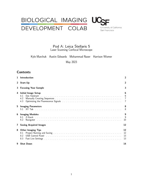
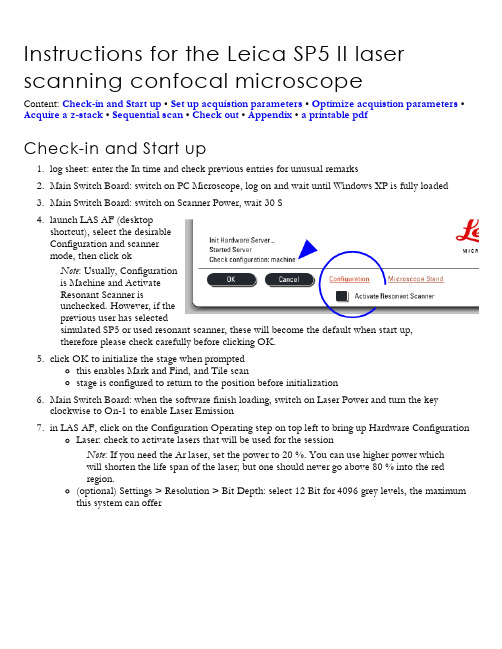
Pod A:Leica Stellaris5Laser Scanning Confocal MicroscopeKyle Marchuk Austin Edwards Mohammad Naser Harrison WismerMay2023Contents1Introduction2 2Start-Up2 3Focusing Your Sample3 4Initial Image Setup64.1Dye Assistant (6)4.2Manually Creating Sequences (7)4.3Optimizing the Fluorescence Signals (7)5Imaging Parameters85.1XY Tab (8)6Imaging Modules96.1Z-Stack (9)6.2Navigator (10)7Saving Acquired Images12 8Other Imaging Tips128.1Project Naming and Saving (12)8.2USB Control Panel (13)8.3Fast Live Settings (13)9Shut Down141IntroductionThe Leica Stellaris5is an inverted laser scanning confocal with4laser lines(405nm,488nm,561nm,and638 nm).It features3next-generation Hybrid Detectors(HyDs).All new users need to be trained by a BIDC staff member before independent use.Sign up for time using the iLab microscope scheduler.The objectives available for use on the Stellaris5are:Objective Mag NumericalAperture Immersion WorkingDistanceID NumberHC PL Fluotar5x0.15Air13.7mm506224 HC PL APO CS220x0.75Air0.62mm506517 HC Fluotar VISIR25x0.95Water 2.40mm506375 HC PL APO CS240x 1.30Oil0.24mm506358 HC PL APO63x 1.40Oil0.14mm506350 2Start-Up1.Turn On the two power switches on the left side of the microscope control box.See Figure:1.NOTE:The key should always be On and the microscope power box should always be On.Figure1:The power supply switches located to the left of the computer desk.2.Turn On the computer tower.3.Log into the User account.unch the LAS X software from the desktop.5.Confirm that the machine configuration and the DMI8microscope are selected at the first prompt.SeeTop Figure:2.6.Ensure the stage area is clear of obstructions and Initialize the stage in the second prompt.See BottomFigure:2.Figure2:The two prompts to launch the software.3Focusing Your Sample1.Select your objective in the software(See Top Figure: 3.)or on the front panel of the microscope(SeeBottom Figure:3.).Figure3:Options for selecting the objectives.2.Add an immersion media to the objective if needed.3.Place your sample into the appropriate sample holder.4.Add the sample holder to the stage.e the xy-stage controller to align the sample above the objective.6.On the front of the microscope navigate to the filter panel menu.See Red square Figure:4.7.Select FLUO for the Incident light.See Blue square Figure:4.8.Press the IL-Shutter to shine light on the sample.See Green square Figure:4.9.Slowly raise the objective using the z-control until your sample comes into focus.Figure4:Widefield illumination panel.4Initial Image Setup4.1Dye AssistantFigure5:Dye Assistant Interface.The Dye Assistant is a useful tool to quickly generate acquisition sequences for multiple fluorophores.The software can optimize for speed of acquisition or minimal fluorescence bleedthrough between channels.1.Click on the Dye Assistant Icon near the top-middle of the main screen.See...2.Press the’...’Icon and search for your fluorophore.3.Continue until all fluorophores are added.4.Apply one of the proposed sequences.None Sequential:All channels will be acquired simultaneously.This is the fastest option,but it is limited to3channels.This will likely have the most Crosstalk of the suggested settings.Line Sequential:Switches Sequences each line of the images scanned.To maximize speed,Channels that share a Detector need to have the same Bandpass width.Frame Sequential:Switches Sequences at the end of each image plane.No limitation on the width of the Bandpass window.Switching the hardware this way increases time.Stack Sequential:Switches Sequences at the end of each Stack.Considerably faster than Frame Se-quential and no limitation on Bandpass width.5.Once a sequence in the Dye Assistant has been selected,the program will ask if you want to turn on thelasers needed for imaging.Select Yes.6.Ensure the microscope arm is in place prior to going Live.4.2Manually Creating SequencesFigure6:Sequence Interface.1.Press the’+’Icon to add the number of Sequences you would like.2.Search for a fluorophore in the Search Bar.3.Drag the fluorophore Icon down to the Sequence you want to place it in.4.Continue adding all your fluorophores to the Sequences.5.Choose whether you want Line Sequential,Frame Sequential,or Stack Sequential by choosing theappropriate Icon(see above).6.When you are happy with your Sequence you can Save it to your directory by pressing the Down ArrowIcon.4.3Optimizing the Fluorescence SignalsFigure7:Tools to quickly optimize your image intensity.1.Click Live or Fast Live in the lower-left of the screen to start imaging the selected Sequence.2.Ensure the sample is in the imaging plane by adjusting the Z-position using the dial on the smart panel.You may need to adjust the Look up Table(LUT)slider to see signal.3.Select the Over/Under Saturation display for the live images.4.Click on a displayed image to select that channel for gain adjustment.5.Adjust the laser power and gain until you have a bright image just below saturation(blue pixels).6.Click on the Capture Image button to collect and save an image of that Sequence.7.Click on the Start button to collect and save an image of all Sequences.5Imaging ParametersAfter setting up the laser and gain acquisition settings for the sequences,the user can set up the rest of sample acquisition parameters.5.1XY TabFigure8:XY TabIn general,used for setting up XY parameters pertaining to how images are captured.Format:The size of the image in pixels.Suggested size is1024x1024for most applications.Speed:Image acquisition speed.Suggested speed is600Hz.Speed faster than600Hz will require increasing the Zoom of the image.Bidirectional X:Data is collected on both movement directions of the X galvo.Some acquisition parameters are tied to this setting.Zoom Factor:Digital Zoom of the image.Increasing the magnification of the objective will give a better image and optical section capability.Zoom In:Press this button to draw an ROI on the image.The microscope will zoom on the ROI.Image Size:Describes the size of the image in microns.This is dependent on the Objective,Format,and Zoom Factor.Pixel Size:Describes the size of the pixel in microns.Optical Section:Thickness of the image plane.Pixel Dwell Time:Length of data collection for each pixel.Frame Rate:Time required to collect a single sequence at a given image plane.Line Average:Number of times each line of the image will be acquired and averaged to produce the image.Used to reduce noise.Line Accu:Number of times each line is accumulated(summed)to produce and image.Can be used on very dim samples.Frame Average:Number of times each frame of the image will be acquired and averaged to produce the ed to reduce noise.Frame Accu:Number of times each frame is accumulated(summed)to produce and image.Can be used on very dim samples.Auto Gain:The system will increase the gain to optimize the image with the current laser power.Rotation:Rotation of the image.Pinhole:Used to adjust the pinhole size.Increasing the pinhole produces a brighter signal at the expense of your optical section capability.6Imaging Modules6.1Z-StackFigure9:Available settings for the volume acquistion.Used for creating the volumes of a3D stacked image.Begin:Using the Z-Position knob,move the image plan to the Top of your sample and press this button to assign this position.End:Using the Z-Position knob,move the image plan to the Bottom of your sample and press this button to assign this position.Trash Can Icon:Deletes your position assignments.Stack Direction(Z):Scanning direction for the volume acquisition.Typically,you want to move the stage toward the objective to scan into your sample.Number of Steps:Volume divided by Z-Step Size.Z-Step Size:Volume divided by Number of Steps.System Optimized:Determined by the objective;the smallest Z-Step Size before over-sampling the volume. Z-Compensation:Is used to associate laser power and gain with z-position.Typically,it is used to compensate for scattering in a thick sample.1.Check which options you’d like to associate with z-position.Excitation Gain is laser intensity.Emis-sion Gain is the HyD gain.2.Navigate to an imaging plan within your volume and adjust the laser intensity and HyD gain to yoursatisfaction.3.Move to other planes and repeat the process.4.Delete any positions you do not need or may have loaded when you started.5.Select your next Sequence and repeat the process.Travel Range:Full distance the z-stage can travel.6.2NavigatorThe Navigator Module is a large-area exploration tool that is capable of setting up multiple ROIs of different sizes for tiled-image acquisition.The navigator can be opened by clicking the grid icon in the top left corner of the main LAS X window.Figure10:Navigator IconOnce open,you should see a white box on a gray background.This box represents the current field of view of the stage.When opening the navigator for the first time,this box will be located at last field of view seen in the main software window.Beam Path Tab On the Stellaris,individual settings can be temporarily turned on and off by checking and unchecking the box in the top left corner of each setting in the Beam Path tab.Having less settings active when spiraling will greatly increase the tile it takes to create a tiled preview.Moving the Stage:Double-click on the viewing area and the stage will move and take a preview tile using the currently selected sequence.Live:Press the Live button to continuously view the current stage position depicted by the white box.Fast Live:Press the Fast Live button to continuously view that stage position in a lower resolution(faster than Live).Spiral Press the Spiral button to engage the stage in an expanding pattern for exploration.ROIs Using the ROI shape tools,draw ROIs on the stage area for exploration or experiment acquisition.Figure11:ROI&Focus Map tools located at the bottom-center of the screenPreview Press Preview and the microscope will do a fast acquisition of the drawn ROIs.Start Press Start to run the experiment from the Navigator.Any ROIs created for tiling will be listed in the tab in the bottom right of the screen.Shapes can be either deleted or temporarily turned off using this tab.Figure12:List of all created ROI shapes to be imaged.Focus Map For uneven tissues,individual focus points can be manually placed and each associated with a unique Z position in order to correct for the uneveness of the sample.1.Select either the blue focus point or green auto-focus point from the options next to the ROI tools.See Figure11.2.The Focus Map option will now be illuminated.Select Focus Map,and click on the first focus pointlisted.3.The software will zoom in on a live view of the field of view surrounding the selected focus point.Adjust the Z position until the sample is in the desired focal plane.4.Once satisfied,select Set Z to associate the focus point with the current Z position.5.Hit Next.Then repeat steps3-5for each focus point placed.Figure13:Focus Map Tab7Saving Acquired Images1.Click the Experiments tab to view all images taken.2.Delete or Rename images as needed.3.Click Save All to save images as a.lif file to your hard drive.4.Please remove old files from the Stellaris computer once they have been saved on your hard drive or Box. 8Other Imaging Tips8.1Project Naming and SavingIt is important to adopt a project naming and saving convention to avoid future headaches when trying to analyze the data.1.Save your Project file with a name that identifies the experiment.We recommend this to be either a slideidentifier or an experiment identifier with a date.2.Rename the images within the Project file with descriptions of the image type.We recommend makingnote of whether the images are z-stack,tiles,timelapse,etc.This will make it easier to’unpack’the imageslater.8.2USB Control PanelFigure14:Can be customized for your workflow.The USB Control Panel can be customized to include controls you may want to readily access.For example, the xy stage position can be controlled similarly to the z-piezo.To add additional features:1.Press the USB Panel shortcut button.2.Select a dropdown and change it to x Position(Stage).3.Select another dropdown and change it to y Position(Stage).To change the speed at which the z-stage moves:1.Located below the Z-Position dropdown(far right):2.Select the speed you wish the stage to move per full turn of the wheel on the USB bar.8.3Fast Live SettingsFigure15:Interface for the Fast Live settings.Pressing the Fast Live’gear’icon allows you to change the XY imaging settings while in Fast Live.The BIDC recommends256x256at600Hz with Bi-Directional scanning On.9Shut Down1.After saving,close the LAS X software.2.Shut down the computer using Shut Down option in the Start Menu.3.Remove samples and clean objectives as needed.4.Press the two Power Switches to turn off the entire system.5.Replace dust cover and clean the area.Contact the BIDCThe BIDC office is located in Medical Sciences Building Room S1109.The BIDC office phone number is415-476-4550.If you need immediate assistance and no one is available in the office,or it is after business hours,please call the BIDC Hotline at415-745-2432.。
共聚焦使用指南
共聚焦使用指南一、开机1.打开显微镜开关,汞灯开关,电脑开关(地上)。
2.打开激光器开关按钮(右边3个,左边1个(观察DAPI))。
若只分析图片,只开PC/Stand的开关。
3.电脑上打开软件Leica confocal software:公司模式。
4.打开激光外器钥匙(右边3个,左边1个(观察DAPI))。
若只分析图片,不用打开钥匙。
5.488激光调节器(LevelAr/ArKr)至水平状态。
若只分析图片,不用调节此处。
二、显微镜下观察1.放好样品。
2.显微镜身左边:分光拉杆拉至中间,转盘调至相应激发光。
3.显微镜身正前方:Poris调至VIS;MAG调至1x。
4.选择合适倍数调好焦距:荧光弱需要大倍数200x,400x采集图片。
三、电脑下观察采集图片(选择第一通道)1.显微镜转盘转至SCAN,分光拉杆全部推进。
2.显微镜身正前方Poris调至side;MAG调至B灯亮后回调至UV。
3.电脑软件左下角microcontrol选择SCAN。
4.点击软件左下角Beam,选择荧光通道(用途)。
5.双击选择Beam右上角DAPI ,点击软件左下角Continous实时观察。
6.显示窗口Experiment的Qlut看曝光是否过度(蓝色表示过度),可调节Beam左上角的ND值,桌上PMT1和pinhole(此值一般AE在1-1.5,慎调)控制曝光;ZOPS可调节图片Z轴聚焦。
7.点击Beam上Save(回车2次)。
8.Continous调至STOP关闭实时观察。
(选择第二通道)9.双击选择Beam右上角ZZ-FITC,点击软件左下角Continous实时观察。
10.显示窗口Experiment的Qlut看曝光是否过度(蓝色表示过度),可调节Beam上的488通道的百分值,桌上PMT1和pinhole(此值一般AE在1-1.5,慎调)控制曝光;ZOPS可调节图片Z轴聚焦。
11.点击Beam上Save(回车2次)12.Continous调至STOP关闭实时观察(选择第三通道)13.双击选择Beam右上角ZZ-TRITCwide,点击软件左下角Continous实时观察。
Leica激光扫描共聚焦显微镜快速操作手册

可通过调节控制面板的“Z Position”旋钮找到最适合观察的焦平面(如 下图);或者调节遥控手轮或显微镜镜体上的调焦旋钮(见第 8 页图)。
图像亮度动态范围可通过调节激光输出功率(见第 9 页图)、Smart Gain 和 Smart Offset(见上图)。
针孔大小:默认值为 1AU。如果样品的荧光非常弱,可通过增大针孔直 径来增加信号强度,所获取图像的光切厚度也会随之增加。
平均:用于降低背景噪音。分为线平均(Line average)和面平均(Frame average),可在下拉菜单中选择平均的次数。
累加:仅用于荧光非常弱的样品
10
2.4.3 预览图像
物镜选择按钮 预览按钮 Live 拍摄按钮 叠加图像显示按钮,在使用两个或以上数量通道拍摄多色图像时,用于显示 所有通道叠加后的图像
7
2.3 在显微镜下观察样品
2.3.1 选择物镜:可通过显微镜主机右侧的物镜转换按钮,或软件中的“Objectives” 键进行选择。(如下图)(注意:有时,显微镜主机上的物镜转换按钮不能在干镜 和油镜或水镜之间切换,软件中都可以切换)
8
2.3.4 观察完毕后,按显微镜前面板上的“SHUTTER”按钮以保护样品
2.4 采集共聚焦图像 2.4.1 光路设置:
调用已有的设置:选择“Load/Save single setting”下拉菜单中已有的设置,激光波长及 其输出功率、分光镜、检测波长范围、检测器 gain 及 offset 都会自动设置,包含几种最常用 的荧光染料。选择某一设置后,可按样品的实 际情况对参数进行优化(如后述),并以新的名 称保存。(如右图)
激光共聚焦显微镜中文说明书

激光共聚焦显微镜中文说明书12020年4月19日激光共聚焦显微镜FV1000(倒置显微镜IX81) 简易使用说明书2 2020年4月19日32020年4月19日开启系统 1.打开计算机.2.打开激光器.(打开钥匙开关.) 2-1.多线氩离子 (458 nm, 488 nm, 514 nm) ON2-2氦氖绿 (543 nm) ON2-3氦氖红 (633 nm) ON 3.打开汞灯电源开关. 4.登陆 Windows XP 系统.User ID: Administrator Password: fluoview5.双击快捷方式:打开 FV10-ASW 应用软件.5231文档仅供参考,不当之处,请联系改正。
42020年4月19日User ID: AdministratorPassword: Administrator* 系统软件的启动需要等待一定时间.显微镜镜下观察 微分干涉差观察1.使用手控面板选择物镜. (参照Memo .)2.插入起偏镜.3.插入微分干涉滑块.*DIC元13 24手控面板用此旋钮进行微分涉法对比度的调.4.点击FV10-ASW软件中的图标.Note1:使用TD滑块控制卤素灯的光强;Note2:检查滤色片转盘的位置是否为“6.DICT”,如果不是,用手柄按下DICT 图标5.标本聚焦Memo显微镜镜下观察荧光观察52020年4月19日619日1.使用手控面板选择物镜.2.点击FV10-ASW 软件中的图标.3.使用手控面板选择荧光滤色片.(参照Memo .)4.标本聚焦.2Hand switchMemo 关于荧光滤NIB : 蓝色激/ 绿色荧(FIT 、 EGFP 等WIG : 绿色激/红 色 荧(Rhodamin 、 DsRed 等72020年4月19日扫描模式扫激光输出的调节明场观察( 显微镜镜下观察) 荧光观察( 显微镜镜下观察 ) 扫描的按钮 选择 XYZ,XYT 或 XYL 每个通道的调节 共聚焦的孔径大小 卤素灯的光强调节 Kalman方式 染料选择 光路图取图条件的保存 调出取图条件TwinScanner设定图像的拇指索引图像显示窗口内存中所显示的文件Lambda扫描的设定 物镜 聚焦时间间隔和时间计数( 用于 XYT 或 XT 扫描)λ 扫描带宽选择描速82020年4月19日文档仅供参考,不当之处,请联系改正。
OLYMPUS激光共聚焦显微镜说明0906
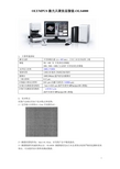
2, 技术特点 同类产品相比有如下技术特点和优势: 1)光学最小分辨为 0.12um,有实例为证。
2)测量的重复性为:3n-1=0.02um, 在同类产品中精度最高。 3)测量数据有权威机构认证,OLS4000 测量精度是由日本品质保证机构严格的追溯体系来 保证,可以提供高可靠性的测试数据。
1
4)光学放大倍数范围:108X---17280X, 108 倍:更宽的视野,可迅速找到测试部位; 17280 倍:突破光学显微镜的放大极限; 5)20X/50X/100X 物镜档次采用显微镜中最高档的―――平场复消色差物镜,
数值孔径(分辨率最高)最大,可以观察更大角度的斜面。
6) 迅速找到测试部位:在操作界面可轻松控制的 100 X 100mm 电动载物台,大画面高倍清 晰图像,小画面低倍宽视野定位图像,即使是在高倍观察时也不会迷路。
2
7) 便于操作,降低污染或破坏样品可能性的 6 孔电动物镜转盘
8) 多样化的观察方式 明场,明场微分干涉,激光共焦,激光共焦微分干涉
3
9) 可以克服同一画面内有不同反射率的双共焦光学系统
双共焦系统
10)
INR(智能降噪Biblioteka 演算方式11)内置减振机构,再不用配笨重的防振台
4
3, 检测内容 1)高分辨率二维形态观察,真实色 2 维观察; 2)高分辨率三维形貌观察,真彩三维形貌观察, 3)高精度测量:线宽,高度测量,线粗糙度,面粗糙度,面积,体积测量,几何测量,直 径/半径测量,圆周长,颗粒分析,膜厚测量等。
OLYMPUS 激光共聚焦显微镜-OLS4000
1, 主要性能指标
激光光源 物镜 光学放大倍率 观察范围 载物台 二维分辨率 Z 轴最小移动分辨率 X 轴方向测量重复精度 Z 轴方向测量重复精度 半导体激光器 (λ = 405 nm ) 5X / 10X 为 半复消色差物镜 20X / 50X / 100X 为 LEXT 专用复消色差物镜 108X-17280X 128X128 微米-2560X2560 微米 100X100mm 超声波电动载物台 0.12 m 0.01 m (光栅尺刻度为 0.0008 m) 3n-1=0.02 m (条件为使用 MPlanApo100 物镜) =0.012 m。 (条件为使用 MPlanApo100 物镜) 日本工业安全标准 2 级
leica共聚焦显微镜使用说明

Leica共聚焦显微镜使用说明Step 1: 打开PC电源——“1”Step 2: 打开汞灯控制开关——“2”Step 3: 打开中控盒——“3”Step 4: 打开计算机主机——“4”,启动计算机。
注:计算机操作系统启动后方可继续开机!!Step 5: 顺序打开激光器电源Scanner—“5”,激光冷却系统LASER Ar/ArKr—“6”★注:须确认冷风开启后方可打开激光电源!!!!!Step 6: 将上图虚线框中激光功率控制旋钮——“6.5”顺时针旋转60°左右。
Step 7: 将上图所示488 nm激光管开关——“7”钥匙沿顺时针旋转约120°至显示灯亮,再将钥匙旋回竖直位置Step 8: 依次将上图所示543/594 nm激光管开关——“8”和633 nm 激光管开关——“9”钥匙沿顺时针旋转约90°至显示灯亮。
Step 9:依次打开半导体激光器电源——“10”和405 nm激光管开关——“11”,(“11”的开启方式同“8”、“9”。
)Leica共聚焦显微镜关机顺序及注意事项Step 1: 关闭软件→拷贝Data→关闭计算机Step 2: 依照开机顺序倒序关闭各个开关,由”11”→”7”, ”5”→”1”。
★注:(1)冷风——”6”不能立即关闭!!须在关闭所有硬件设备30min 后方可关闭,以使激光管完全冷却,延长使用寿命。
(2)PC电源——“1”须在电脑确定关闭后方可关闭!!数据采集Step 1: 实验前扫描样本片观察激光通路是否正常工作。
Step 2: 上样,须轻起轻落科勒照明系统,选择合适倍数物镜,通过FLUO键选择相应荧光通道,调节载物台和焦距,找到合适视野。
Step 3: 点击由Visual→Scan,点击选择扫描模式,如xy, xyz, xyt, xyzt, xyλ etc..点击选择扫描格式(一般为默认值512*512)。
Step 4: 点击打开Beam path setting窗口,对光路和检测器进行设置。
激光扫描共聚焦显微镜使用说明
激光扫描共聚焦显微镜使用说明标签:激光扫描共聚焦显微镜使用说明激光扫描共聚焦显微镜可以:(1)光切片扫描、3D图像处理、时间序列拍摄成像;(2)细胞、绿荧光蛋白、生物荧光样品观察分析;(3)荧光原位杂交分析。
详细实验方法共聚焦显微镜激光扫描法实验方法原理激光共聚焦扫描显微镜(Confocal laser scanning microscope,CLSM)用激光作扫描光源,逐点、逐行、逐面快速扫描成像,扫描的激光与荧光收集共用一个物镜,物镜的焦点即扫描激光的聚焦点,也是瞬时成像的物点。
由于激光束的波长较短,光束很细,所以共焦激光扫描显微镜有较高的分辨力,大约是普通光学显微镜的3倍。
系统经一次调焦,扫描限制在样品的一个平面内。
调焦深度不一样时,就可以获得样品不同深度层次的图像,这些图像信息都储于计算机内,通过计算机分析和模拟,就能显示细胞样品的立体结构。
实验材料细胞试剂、试剂盒荧光染料水培养基仪器、耗材激光扫描共聚焦显微镜载玻片洗瓶滴管试管实验步骤一、观察及仪器操作1. 开启仪器电源及光源一般先开启显微镜和激光器,再启动计算机,然后启动操作软件,设置荧光样品的激发光波长,选择相应的滤光镜组块。
以便光电倍增管(photo multiplier tube,PMT)检测器能得到足够的信号结果。
使用汞灯的注意事项同普通荧光显微镜。
2. 设置相应的扫描方式在目视模式下.调整所用物镜放大倍数,在荧光显微镜下找到需要检测的细胞。
切换到扫描模式,调整双孔针和激光强度参数,即可得到清晰的共聚焦图像。
3. 获取图像选择合适的图像分辨率,将样品完整扫描后,保存图像结果即可。
4. 关闭仪器仪器测定样品结束后,先关闭激光器部分,计算机仍可继续进行图像和数据处理。
若要退出整个激光扫描共聚焦显微镜系统.则应该在激光器关闭后,待其冷却至少10分钟后再关闭计算机及总开关。
二、获取三维图像激光扫描共聚焦显微镜具有细胞“CT”功能,因此,它可以在不损伤细胞的情况下,获得一系列光学切片图像。
Leica SP5 II激光扫描共聚焦显微镜使用说明书
Set up acquistion parameters and acquire an image1. Beam Path Settings in the central Work area: there are 3 ways toconfigure excitation and emission parametersA. use a preseti. click on Load/Save single settingii. select a Leica or User Settings (for multichannels, thedefault is simultaneous scan, see below for sequentialscan)B. reuse a setting from a previous scani. open a previous experimentii. in the Experiments tab, click to select the desirablescaniii. right-click to choose Apply Setting or hit Apply buttonat the bottomC. assemble from scratchi. set laser poweractivate the shutterset power level of the desirablelaser line, 5 % is a good startingpointii. select the beam splitter (dichroic)selections for different laser linesbeam splitter\laser line (nm)RT 30/70 for backscatter or reflectionSubstrateTD 488/561/633DD 458/514RSP 500DD 488/561spectra or details for the beam splitters are in the Appendix405✓✓458✓✓✓476✓✓✓✓488✓✓✓✓514✓✓561✓✓✓633✓✓iii. setup the detectorselect the emission band: drag the lower and upper bounds or double click the slider to enter the begin and end wavelengthsCaution : Drag the sliders slowly or else they will jam!click on PMT n to adjust PMT Gain* and Offset*; good starting values are 800 and 0,respectivelyselect a LUT as default activate the PMT2. select the Acquire Operating step on top left, click the Acquisition tab to set up the data formatA. Acquisition mode paneldefaults to xyz simultaneous scan seq. button enables sequential scan Tile scan, and Mark and Find Best Focustop left side of the viewer display Window: activate the Glow (OU) LUT via the Quick LUT button which cycles through the default , Glow (OU) , and grey LUTsii. adjust offset so the pixels in the area you think should be darkest just turn green,click the button on Acquistion Mode on the upper left to open the Sequential Scan panelclick to toggle displaying the Tile Scan windowgo Livemove the prep/stage to the left boundary of the region of interest, focusclick to mark the current positionrepeat the last 2 steps for the top, right, and bottom boundries, the software will calculate theMark and Findclick to toggle displaying the Mark and Find windowif there are existing coordinates, you can save or clear them firstmove the prep/stage to the desirable area and focus on the object of interestclick to mark the current position, which will be listed as positionNrepeat the above 2 steps to mark more positions as needed, i.e., positionN+1, N+2... etc.you can go back to any position by selecting it from the drop down listAppendixContentDMI 6000 inverted microscope: basic controls • modes of operation • using immersion objectives beam splitter spectra • working with lif files • scannersoft ware ov erv iew and layoutLAS AF user int erfaceDMI 6000 inv ert ed microscopeCont rolsfocus knob on either side of microscope (z-Wide)commonly used functions are controlled by 5 sets of buttons1. left rear variable function buttonsCHG TL ◑: switch to transmitted light, TL and rotate through different modes TL_BF(bright field), _DIC, _POL (polarization)CHANGE CS: toggle between confocal SCAN and the last selected TL modeCOMBI ◑: epifluorescent + DICZ COARSE Z FINE: toggle z control2. left front: Illumination ManagerTL/IL: toggle between TL and IL(incident-light i.e., epifluorescence)AP: aperture diaphragm for TLINT : light intensity, press both togetherto toggle between Coarse and Fine modeFD: field diaphragm for IL3. fronttop row switches should not be activated,or else it may block viewing through thebinocular, to rectifypress the leftmost button to selectbinocularpress the rightmost button todeselect the supplementalmagnification changerSHUTTER: for epifluorescentilluminationbottom 6 buttons: for selecting specific cube (DAPI, GFP, DsRed) for epifluorescence;press the middle 2 buttons together to display the programs assigned to the variablefunction buttons4. right rear variable function buttonsCHGOBJ ↻: rotates the objective turret oneposition clockwise in the current mode (dry orimmersion)CHGOBJ ↺: same as above butcounterclockwiseDRY/IMM: toggles between dry and immersionmode5. right front: Focus buttonsZ ↑: moves the Z drive up when a upper focus stop hasbeen setZ ↓: moves the Z drive downSET + Z ↑: toggles set and unset upper focus stopSET + Z ↓: toggles set and unset lower focus stopSmartMove remote control for stage movements, as observed in theviewer display window of the software1. X2. Y3. Z (focus, z-wide)4. left button set selects Precise or Fast XY movement5. right button set selects FINE or COARSE focus controlfront LCD panel displays the current status1. Contrasting method e.g., TL, FLUO, orSCAN; and IL SHUTTER status2. Objective lens and Magnification, see fronttop buttons above3. Illumination and Apertures4. Camera Ports/Eyepieces, see front topbuttons above5. Focus controlNote:display on the right shows z at0 µm with upper focus stop set andlower focus stop unsetif upper focus stop is unset, display will indicate --.-- mm andindicates lower focus stop is setModes of operat ionTL1. press CHG TL ◑ to rotatethrough BF, DIC, and POL2. adjust intensity (INT) andaperture (AP) as needed3. optional, press CHG CS toscan mode thus shutofftransmitted light4. a knurled wheel (arrowhead)on the left side below theobjective turret adjusts theDIC shear; it's a rather tightspace!IL/epifluorescence1. turn on FLUO (fluorescent light source)2. press the button for the desirable cube, see the front buttons in Controls3. press Shutter to illuminate specimen4. adjust the intensity (INT) and field diaphragm (FD) as needed5. press Shutter to block illumination when done viewinglocate the area of interest with a dry objective and focusclick to bring up the Mark and Find interfaceclick to record the current position: positionNpress and hold Z ↓ to lower the turret completelyobjective to focusclick to dismiss the Mark and Find interface manual (not recommended)TD 488/561/633DD 458/514 is similar to the TD 458/514/594shown hereDD 488/561beam split t er spect raRT 30/70 is 30% reflection and 70% transmissionSubstrate is just plain glass (50/50)RSP 500 is a 500 nm long pass filterTD and DD are triple and double dichroics (transmission bands in blue)working wit h lif fileuse ImageJ and Bio-Formats plugins, see details on using ImageJuse the free Leica LAS AF Lite application from Leica's ftp depository , Windows only scannerdwell time at several common scan speed settingsline frequency (Hz)horizontal scan duration (s)dwell time (µs)max min100.184.949.71000.018.5 5.04000.025 2.1 1.26000.0017 1.40.810000.0010.90.5。
激光扫描共聚焦显微镜操作指南说明书

激光扫描共聚焦显微镜操作指南说明书[激光扫描共聚焦显微镜操作指南说明书]引言:本操作指南为用户提供激光扫描共聚焦显微镜的详细操作流程及相关注意事项。
在使用本设备之前,请仔细阅读本指南,以确保能够正确、安全地操作设备,并获得最佳的成像效果。
一、设备介绍激光扫描共聚焦显微镜是一种先进的显微镜技术,结合了共聚焦成像和激光扫描技术,可以实现高分辨率、三维成像及活细胞观察等功能。
本设备由以下主要部分组成:1. 共聚焦显微镜主体:包括光源系统、光学系统、扫描系统、探测器等核心部件。
请勿对主体进行任何未经授权的拆卸或修改。
2. 控制系统:用于控制设备的开关、成像参数设置、图像采集及处理等功能。
在操作设备之前,请确保控制系统处于正常工作状态。
二、准备工作在操作激光扫描共聚焦显微镜之前,请进行以下准备工作:1. 检查设备:确保设备的电源线、信号线、光纤等连接线路良好,无损坏或松动情况。
2. 准备标本:根据需要观察的样本类型,准备适当的标本片,并在标本片上施加适当的荧光染料。
3. 调整镜片:根据需要选择适当的镜头,并按照设备说明进行安装和调整。
三、操作步骤以下为基本的操作流程,具体步骤可能会因设备型号和厂家而有所不同,请根据实际情况进行操作:1. 打开设备电源:将电源开关置于“开启”位置,待设备启动完全后,检查设备各部分是否正常。
2. 设置成像参数:通过控制系统,设置激光波长、放大倍数、成像模式等参数。
根据标本类型及观察需求,合理选择参数设置。
3. 校准镜片:根据设备说明书,进行扫描头和标本之间的焦距调整,保证成像过程中的清晰度和准确度。
4. 开启激光:根据标本需要,选择相应的激光波长,并逐一打开相应激光。
5. 定位标本:通过显微镜目镜进行初步观察,调整位置和焦距,使标本位于成像区域。
6. 开始扫描成像:在控制系统中选择扫描图像模式,点击“开始扫描”按钮,启动扫描成像过程。
7. 图像采集和处理:根据需要,可设置图像采集的帧数、分辨率等参数,并在采集图像后进行必要的图像处理和分析。
激光扫描共聚焦显微镜操作说明书

激光扫描共聚焦显微镜操作说明书操作说明书激光扫描共聚焦显微镜是一种高端的显微镜设备,具有高分辨率、高灵敏度的特点,广泛用于生物学、医学、材料科学等领域。
为了正确且有效地操作激光扫描共聚焦显微镜,本操作说明书将为您提供详细的指导。
一、设备介绍激光扫描共聚焦显微镜由以下主要部分组成:1. 显微镜主体:负责接收样本的光信号,并进行扫描成像。
2. 激光系统:提供高能量、高稳定性的激光光源,用于激发样本的荧光信号。
3. 探测系统:用于接收样本的荧光信号,并将其转化为图像信号。
4. 控制系统:提供对显微镜参数进行调节和设置的功能。
二、注意事项在操作激光扫描共聚焦显微镜之前,请确保您已熟悉以下注意事项:1. 安全操作:激光光源具有较强的激光辐射,请佩戴适当的激光防护眼镜并避免直接暴露于激光光束下。
2. 样本准备:样本应事先处理好并放置在适当的载玻片上,确保样本表面平整,避免气泡或杂质的干扰。
3. 导入样本:轻轻将载玻片插入显微镜主体的样本台中,并用调节旋钮精确定位样本。
4. 参数设置:根据实验需要,设置合适的激光功率、放大倍数和扫描速度等参数,确保获得清晰的图像。
5. 镜头清洁:定期清洁显微镜镜片,避免灰尘或污渍影响成像质量。
注意使用专用的镜头清洁纸和清洁液。
三、操作步骤基于激光扫描共聚焦显微镜的特点,以下为一般操作步骤的指导:1. 打开设备电源,等待设备启动并进行自检。
2. 调节放大倍数:通过显微镜主体上的放大调节旋钮,调节适当的放大倍数,以便观察到合适大小的图像。
3. 确定激光功率:在控制系统中,设置合适的激光功率以激发样本的荧光信号,避免过高的功率导致样本损伤。
4. 调整扫描速度:通过控制系统中的扫描速度调节器,设置合适的扫描速度,以获得清晰且稳定的图像。
5. 对焦样本:使用显微镜主体上的对焦调节旋钮,将样本调焦至最清晰状态。
6. 开始扫描:通过控制系统中的扫描启动按钮,启动扫描功能,并观察图像显示区域是否居中和清晰。
激光扫描共聚焦显微镜操作手册

激光扫描共聚焦显微镜(A1R-si)操作指南目录第一章:Ti-E 显微镜操作2-7 显微镜光路调节和照明注意事项 6Ti-E 物镜,DIC 插片,DIC 棱镜对照表7第二章:共聚焦开关机8-10 第三章:共聚焦图像拍摄1-38NIS-Elements C 软件开启和操作界面简介1-15NIS-Elements C 的实时图像获得基本操作16-23图像拍摄24-27探测模式(标准探测器)设置28-38 第四章: 图像的保存和查看39-42 第五章:图像分析43-46 附件一、多维拍摄功能和操作方式介绍47-51附件二:图像格式批量转换操作52-53第一章Ti-E 显微镜操作指南(一)认识显微镜各个部件(1)滤光片:包括D---毛玻璃;NCB---色温(8)滤色块转盘(包括DIC 检偏器);平衡片;ND---减光片;“G IF”---绿色滤(9)手动荧光光闸;光片和用于PFS 的红外滤光片;(10)电动焦距调节旋钮;(2)视场光阑;(11)ND 减光片;(3)聚光器升降旋钮;(12)遥控器;(4)起偏器(DIC 用);(13)透射光电源;(5)聚光器对中旋钮;(14)汞灯荧光光源;(6)孔径光阑;(15)PFS 控制器(7)聚光器模块(包括明视场,DIC);(16)HUB 控制器遥控器示意图(根据具体配置有些图标可能不显示)1)物镜切换按钮;2)滤光块,DIC 检偏器切换按钮;3)DIC 检偏器快速切换按钮;4)光路端口切换按钮;5)PFS 开关控制按钮;6)聚光器转盘切换按钮;7)透射光源控制按钮*。
*请注意:CNTL 按钮灯亮,则可以通过遥控器或电脑控制软件来调节透射光源强度,此时显微镜底座左侧光源开关和调节旋钮锁定;CNTL 功能关闭,可以通过显微镜底座开关和旋钮来控制透射光源。
前面板示意图1)状态显示屏;2)PFS 开关按钮和PFS 聚焦状态指示灯(需要选购PFS 部件);3)光路端口切换按钮;4)中间变倍旋纽;侧面板示意图1)调焦旋钮2)粗微调切换按钮3)物镜切换按钮;4)滤光块,DIC 检偏器切换按钮5)透射光光源开关(当遥控器透射光源控制按钮打开时,此按钮无效);6)透射光量度调节旋钮(当遥控器透射光源控制按钮打开时,此旋按钮无效);7)物镜复位;8)物镜向下移动2 毫米;注意:在使用显微镜之前,要把主机底座右后端的黑色HUB 控制器(显微镜示意图15 位置)右侧的电源开关打开。
Zeiss 激光扫描共聚焦显微镜 操作手册

Zeiss 激光扫描共聚焦显微镜操作手册目录:1 系统的组成系统组成及光路示意图实物照片说明2 系统的使用2.1 开机顺序2.2 软件的快速使用说明2.3 显微镜的触摸屏控制2.4 关机顺序3 系统的维护1 系统的组成激光扫描共聚焦显微镜系统主要由:电动荧光显微镜、扫描检测单元、激光器、电脑工作站及各相关附件组成。
系统组成及光路示意图:电脑工作站激光器电动荧光显微镜扫描检测单元实物照片说明:电动荧光显微镜扫描检测单元CO2 培养系统控制器激光器电脑工作站2 系统的使用2.1 开机顺序(1)打开稳压电源(绿色按钮)等待2 分钟(电压稳定)后,再开其它开关(2)主开关[ MAIN SWITCH ]“ON”电脑系统[ SYSTEMS/PC ]“ON”扫描硬件系统[ COMPONENTS ]“ON”(3)打开[ 电动显微镜开关]打开[ 荧光灯开关](注:具有5 档光强调节旋钮)(4)Ar 离子激光器主开关“ON”顺时针旋转钥匙至“—”预热等待约15分钟,将激光器[ 扳钮] 由“Standby”扳至“Laser run”状态,即可正常使用(5)打开[ 电脑开关],进入操作系统注:键盘上也具有[ 电脑开关]2.2 软件的快速使用说明(1)电脑开机进入操作系统界面后,双击桌面共聚焦软件ZEN 图标(2)进入ZEN 界面,弹出对话框:“Start System”——初始化整个系统,用于激光扫描取图、分析等。
“Image Processing”——不启动共聚焦扫描硬件,用于已存图像数据的处理、分析。
(3)软件界面:1 功能界面切换:扫描取图(Acquisition)、图像处理(Processing)、维护(Maintain)(注:Maintain仅供Zeiss专业工程师使用)2 动作按钮;3 工具组(多维扫描控制);4 工具详细界面;5 状态栏;6 视窗切换按钮;7 图像切换按钮;8 图像浏览/预扫描窗口;9 文档浏览/处理区域;10 视窗中图像处理模块动作按钮:Single ——扫描单张图片、并在图像预览窗口显示。
OlympusFV1200激光共聚焦显微镜系统操作手册
Olympus FV1200激光共聚焦显微镜系统操作手册一、开关机步骤1、开机步骤1)打开计算机2)打开汞灯电源开关3)打开显微镜开关4)打开载物台控制器开关5)打开显微镜触屏面板开关6)打开扫描头开关(先开开关键,然后将钥匙顺时针拧到on位置)7)打开激光器①405nm,633nm:打开开关键即可②559nm:先开开关键,绿色指示灯闪烁(约两分钟),停止闪烁后将钥匙顺时针拧到on位置(红灯闪烁,停止闪烁后即开启完成)③多线氩离子(458nm,488nm,514nm):先开开关键,然后将钥匙顺时针拧到on位置8)双击电脑桌面上打开 FV10-ASW 4.0应用软件。
2、关机步骤1)关闭FV10-ASW 4.0应用软件2)关闭激光器(注意: 多线氩离子458nm,488nm,514nm需先关钥匙,等风机散热20分钟后再关闭开关键)3)关闭扫描头(先将钥匙拧到off位置,再关开关键)4)关闭显微镜触屏面板5)关闭载物台控制器6)关显微镜开关7)关汞灯,先关前面off按钮,倒计时30s,再关后方开关键8)关计算机二、显微镜观察1、用触屏面板选择物镜;2、点击触屏面板EPI,选择需要的荧光滤片,如下图:紫外激发/蓝色光蓝色激发/绿色荧光绿色激发/红色荧光)打开,显微镜目镜下观察样品,推动载物台控制手柄可水平方向移动样品,转动调焦旋钮可调节焦距;三、获图XY多通道扫描1、镜下调好之后,点击软件中的按钮,关闭汞灯快门。
2、首先进行软件设置:在Acquisition Setting里将扫描速度设置为8us/Pixel,像素数一般设置为1024*1024。
在Image Acquisition Control里点击Dye List按钮,在染料列表中,双击用于观察的荧光染料(注:再次双击已选项目可取消),然后点击Apply按钮。
3、将Image Acquisition Control面板中Filter Mode里Kalman 打钩选中,设置线平均Line 2次,这样可以降低图像的噪声。
激光共聚焦显微镜操作手册最终版
徐珏2011.12.3 17:59 于苏州宝石御景园目录标准探测模式(DU4)图像拍摄流程 (1)一、软件开启 (1)二、基本设置 (2)[A1 Setting]界面主要功能区域简介 (2)[Setting]界面功能简介 (4)[Filter and Dye]功能区简介 (6)串色现象解释及Line模式图解 (6)Line模式图解 (7)[scan setting]功能区简介 (7)三、获得图像 (8)[Acquisition]功能区简介 (10)放大方式选择按钮简介 (13)图片扫描参数调用简介 (17)JP2格式图片转化为JPG/TIFF格式图片的操作 (18)各通道荧光图像自由叠加的介绍 (18)数据分析 (21)一、ROI区域分析 (21)二、LUTs调节图像荧光亮度 (23)三、去背景 (25)四、标尺添加 (26)六、长度面积等常规测量 (28)七、细胞计数 (28)[Binary Toolbar]界面简介 (32)光谱扫描模式(SD模式) (34)一、SD模式基本设置 (34)[Detector]标签页功能简介 (35)[Binng/Skip]标签页简介 (36)二、图像获得 (37)三、数据分析 (39)[Spectrum Profile]视窗简介 (40)四、光谱拆分 (40)虚拟滤光扫描模式(VF模式) (47)一、VF模式基本设置 (47)[Detector]设置标签页简介 (48)[Gating Setting]标签页简介 (48)二、获得图像 (48)时间序列拍摄 (49)[Capture Timelapse]视窗简介 (49)[ND]界面简介 (51)[Time Measurement]界面简介 (53)[Capture Z-series]视窗简介 (55)拼大图拍摄 (60)光活化序列拍摄 (61)[Photo Acquition]功能区简介 (62)[Sequential Stimulation]界面简介 (63)常见细胞类型和细胞器形状 (65)常用荧光染料及应用领域 (68)标准探测模式(DU4)图像拍摄流程一、软件开启1、双击桌面NIS-Element图标。
LeicaTCSSP2激光共聚焦显微镜系统操作手册
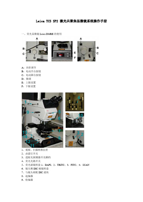
Leica TCS SP2 激光共聚焦显微镜系统操作手册一、荧光显微镜Leica DMRE的使用A:步距调节B:电动升台按钮C:电动降台按钮D:微调E:上限设置F:下限设置1、观察、扫描转换拉杆2、卤素灯开关3、透射光探测器开光横档4、荧光光路开关5、荧光滤镜转盘1:DAPI;2:TRITC;3:FITC;4:SCAN6、镜头侧DIC棱镜转盘7、与镜头相配DIC滤块8、起偏器9、检偏器10、镜头侧DIC棱镜微调旋钮11、光强调节纽12、减光滤光片13、孔径光阑14、视场光阑选择合适的镜头Leica TCS SP2 镜头配置镜头类型使用介质放大倍率/数值孔径编号HC PL APO CS DRY 10X /0.4 506511HC PL APO CS DRY 20X/ 0.7 506513HC PL APO CS DRY 40 X 0.85/ CORR 506140HC PL APO Ibd.BC OIL 63X /1.4 506192Leica TCS SP2 AOBS 镜头配置镜头类型使用介质放大倍率/数值孔径编号HC PL FLUOTAR DRY 10X/0.3 506505HC PL FLUOTAR DRY 20X/0.5 506503HCX PL APO OIL 40X/1.25-0.75 506176HC PL APO Ibd.BC OIL 63X/1.4 506192 HCX PL APO CS OIL 100X/1.40-0.70 506038 WATER HCX APO L U-V-I WA TER 63X/0.9 506148荧光观察荧光光路开关至“O”位,转轮至“1.0×”位,转换拉杆完全推进,荧光滤块换到相应号位(1:DAPI;2:TRITC;3:FITC;4:SCAN)图像输出扫描荧光光路开关至“I”位,转轮至“UV”位,转换拉杆完全拉出,荧光滤块换到4:SCAN)荧光观察(以油镜观察为例)1、样品正面朝上正确放在显微镜样品台上,点上镜油。
- 1、下载文档前请自行甄别文档内容的完整性,平台不提供额外的编辑、内容补充、找答案等附加服务。
- 2、"仅部分预览"的文档,不可在线预览部分如存在完整性等问题,可反馈申请退款(可完整预览的文档不适用该条件!)。
- 3、如文档侵犯您的权益,请联系客服反馈,我们会尽快为您处理(人工客服工作时间:9:00-18:30)。
激光共聚焦显微镜中文说明书
1
2020年4月19日
激光共聚焦显微镜
FV1000
(倒置显微镜IX81) 简易使用说明书
2 2020年4月19日
3
2020年4月19日 开启系统
1.打开计算机.
2.打开激光器.(打开钥匙开关.)
2-1.多线氩离子 (458 nm, 488 nm,
514 nm) ON
2-2氦氖绿 (543 nm) ON
2-3氦氖红 (633 nm) ON
3.打开汞灯电源开关.
4.登陆 Windows XP 系统.
User ID: Administrator
Password: fluoview
5.双击快捷方式:
打开 FV10-ASW 应用软件.
5 2 3 1
文档仅供参考,不当之处,请联系改正。
4
2020年4月19日 User ID: Administrator
Password: Administrator
* 系统软件的启动需要等待一定时间.
显微镜镜下观察
微分干涉差观察
1.使用手控面板选择物镜.
(参照Memo .)
2.插入起偏镜.
3.插入微分干涉滑块.
*DIC 元1
3
2 4
手控面板
用此旋钮进行微分涉法对比度的调.
文档仅供参考,不当之处,请联系改正。
4.点击FV10-ASW软件中的图标.
Note1:使用TD滑块控制卤素灯的光强;
Note2:检查滤色片转盘的位置是否为“6.DICT”,如果不是,用手柄按下DICT 图标
5.标本聚焦
Memo
显微镜镜下观察
荧光观察
5
2020年4月19日。